The Microstructure, Mechanical Properties, and Corrosion Resistance of UNS S32707 Hyper-Duplex Stainless Steel Processed by Selective Laser Melting


Abstract
:
1. Introduction
2. Materials and Methods
3. Results and Discussion
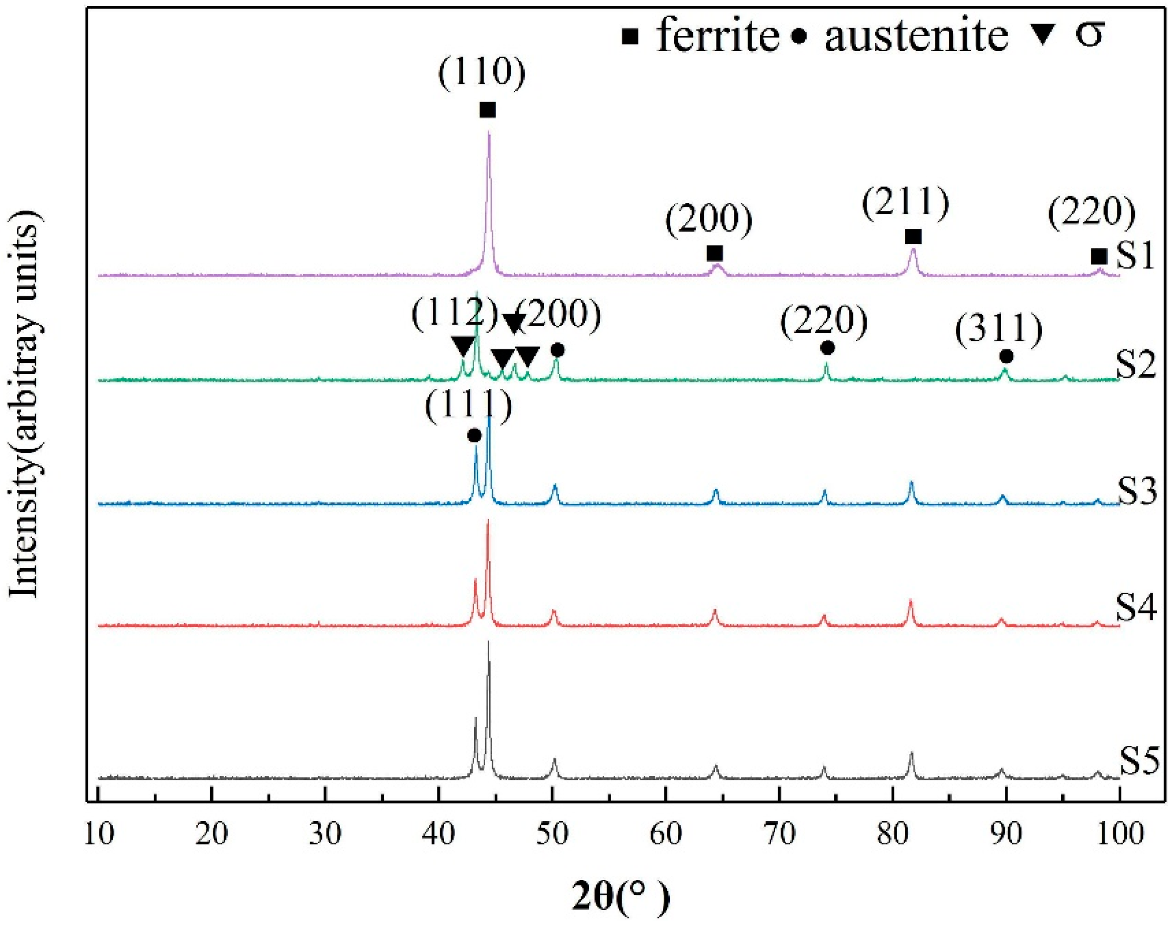
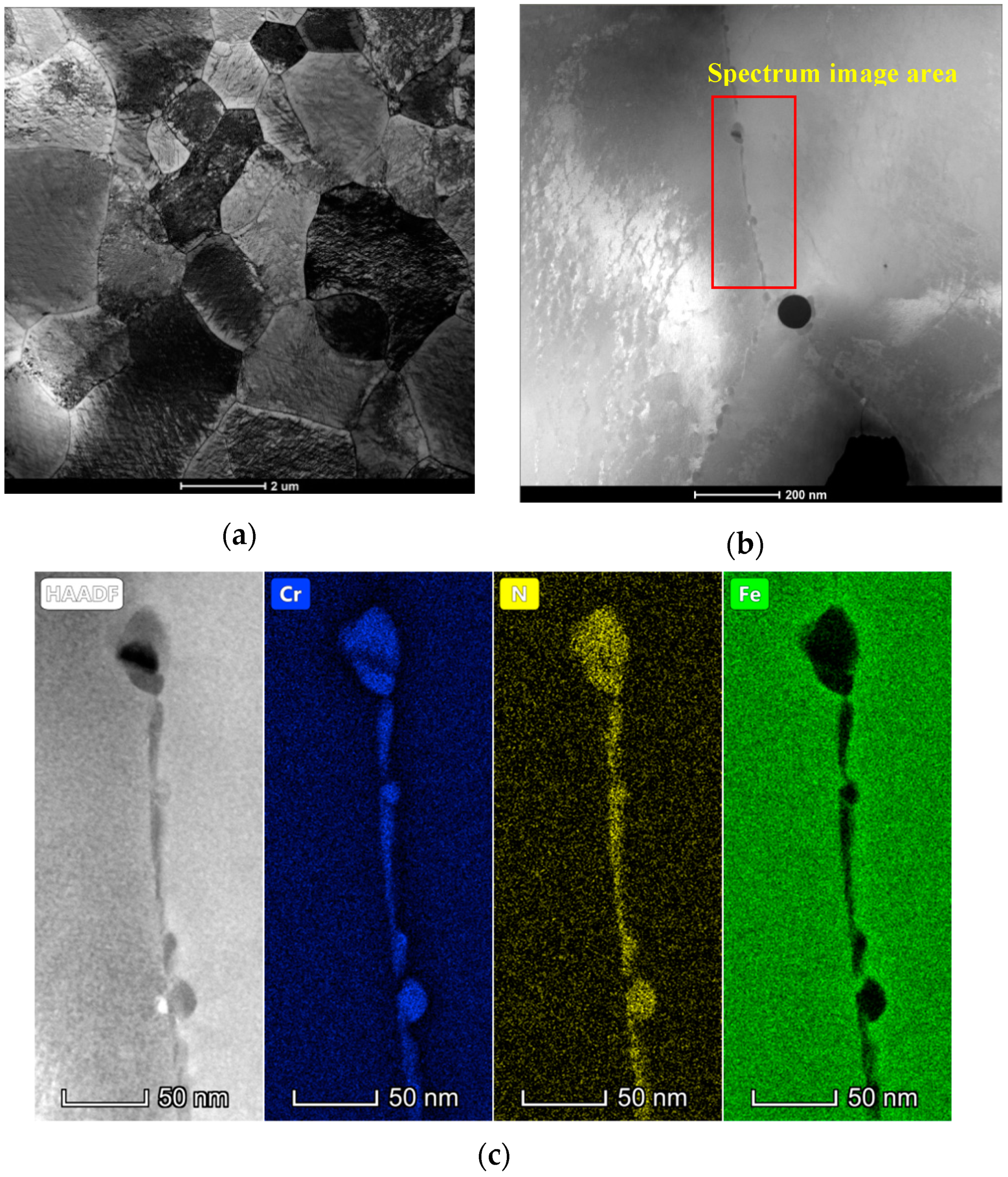
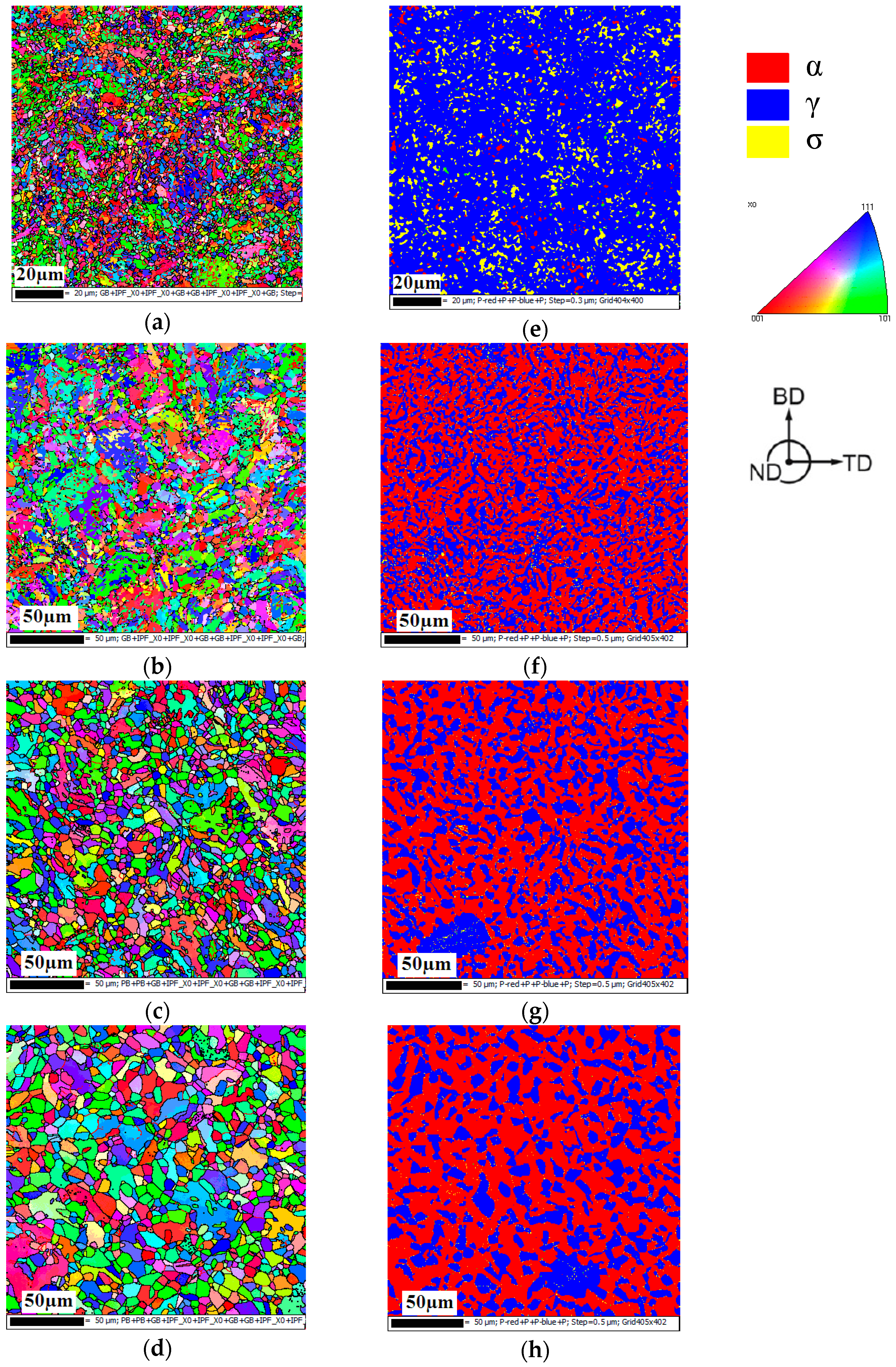
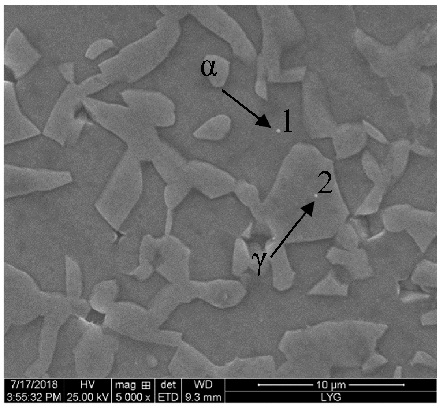
3.1. Microstructure
3.2. Mechanical Properties
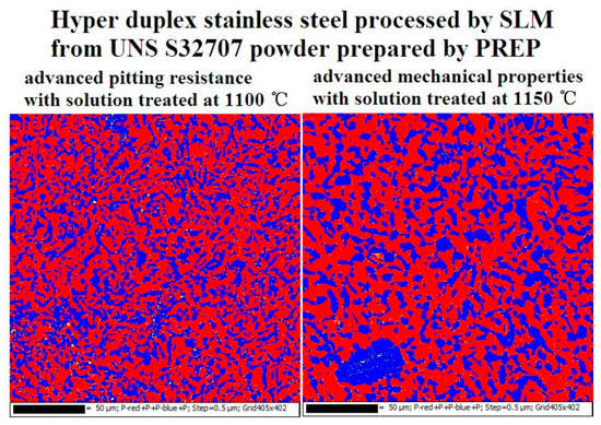
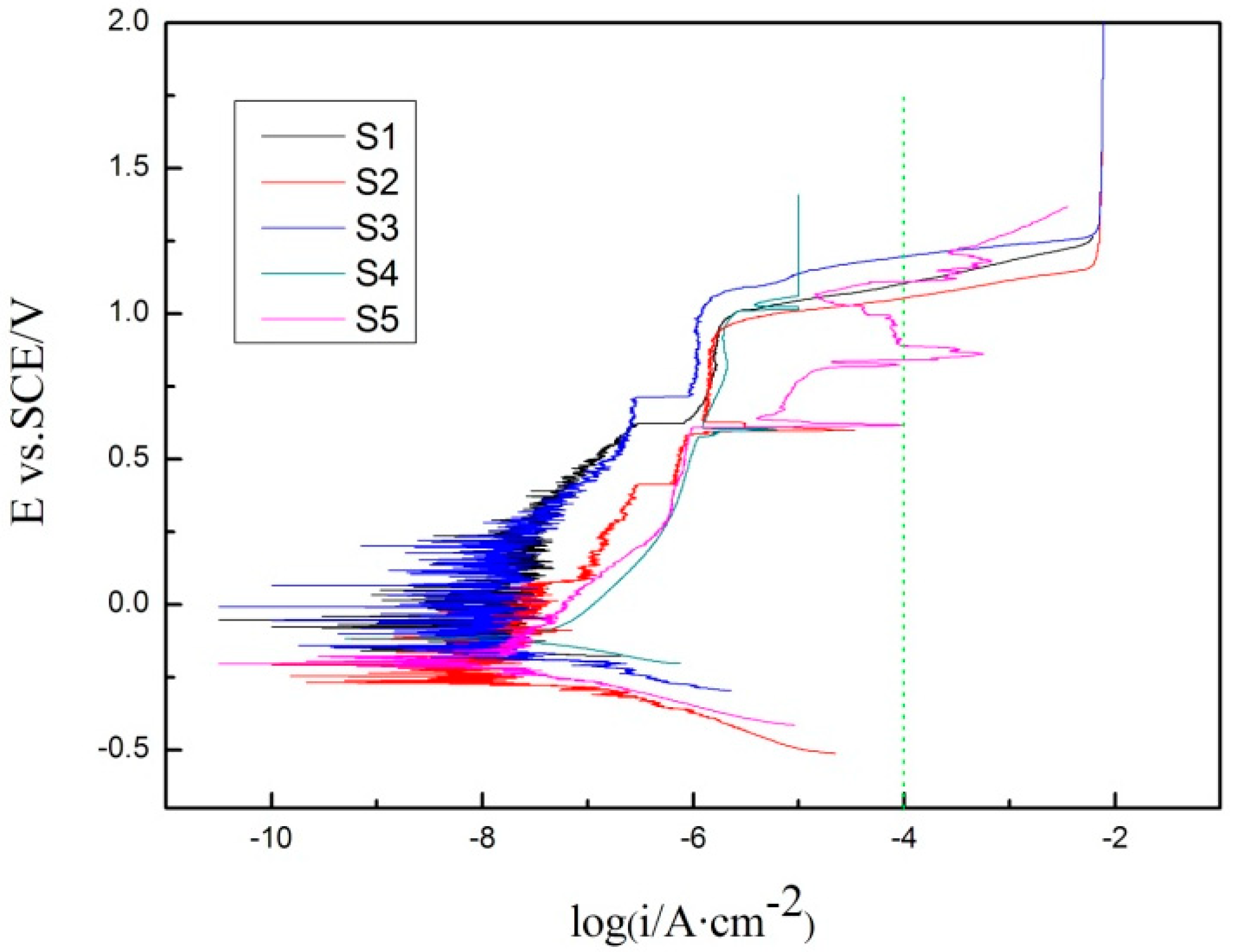
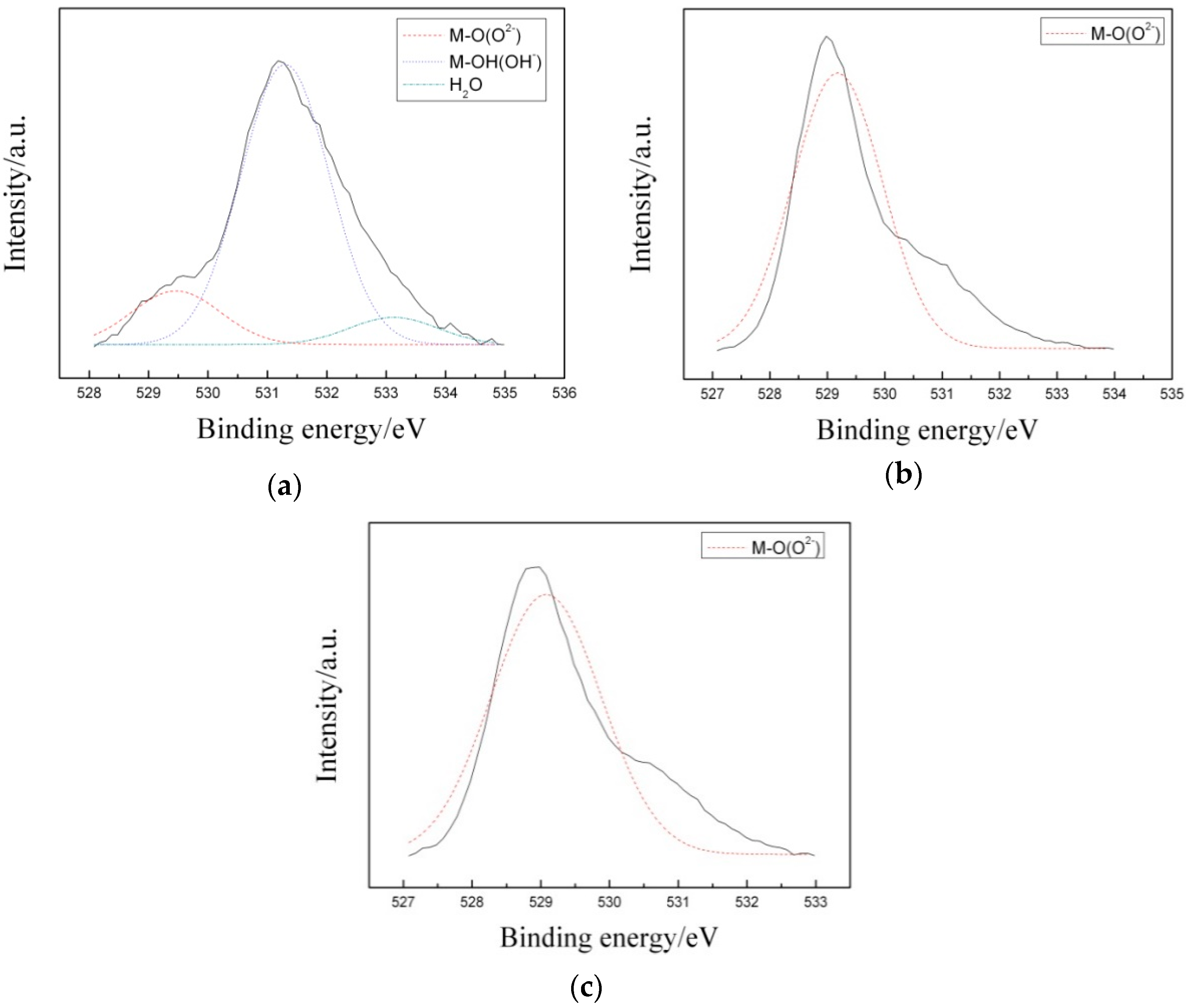
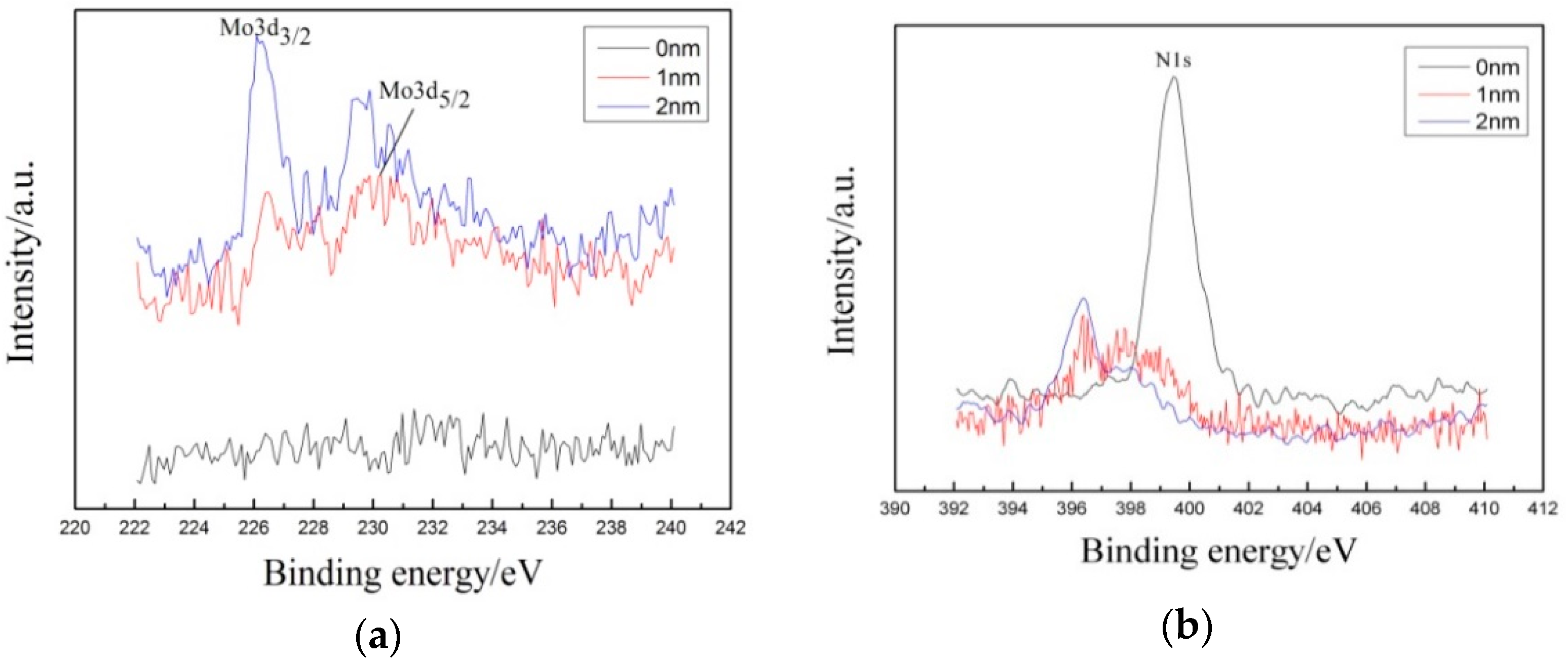
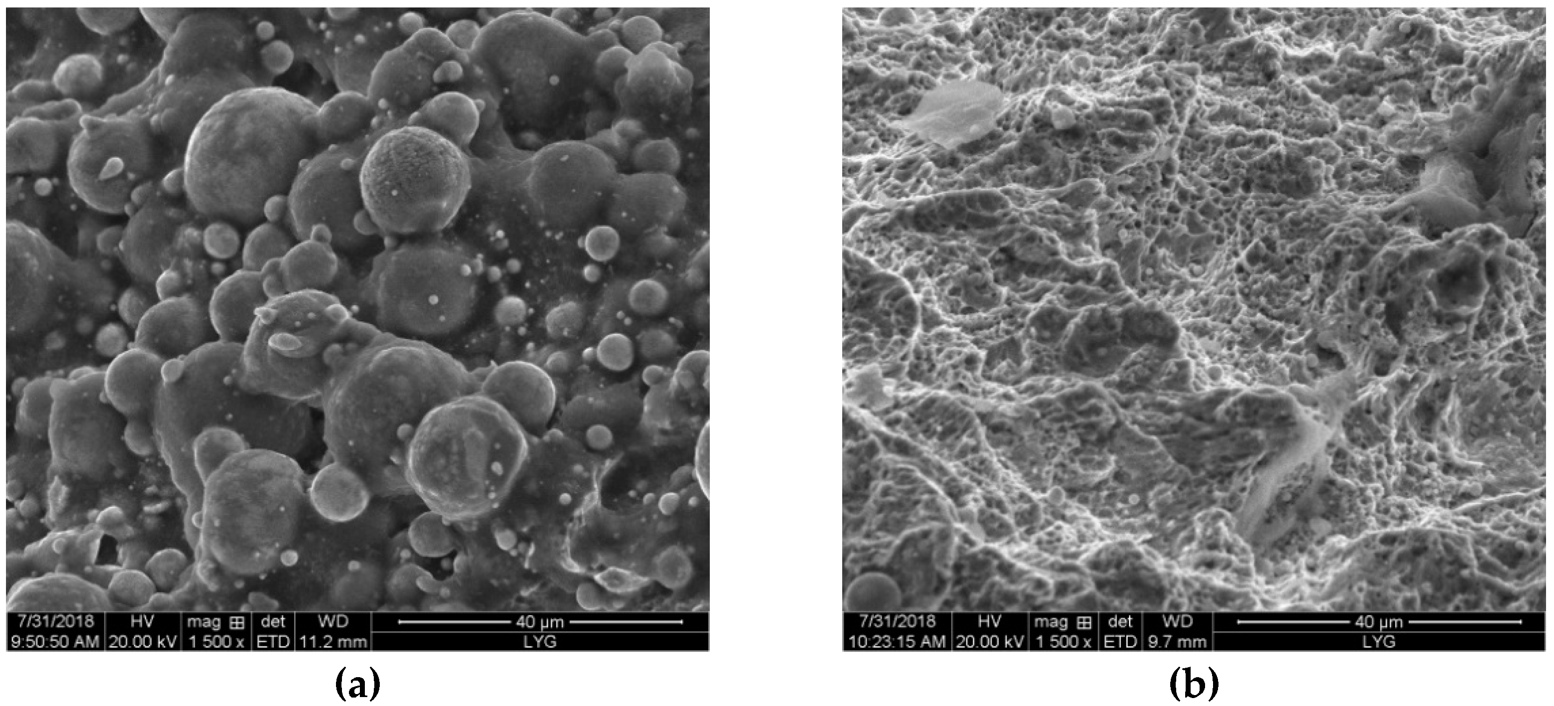
3.3. Corrosion Resistance
4. Conclusions
Author Contributions
Funding
Acknowledgments
Conflicts of Interest
References
- Chail, G.C.; Kangas, P. Super and hyper duplex stainless steels: Structures, properties and applications. Procedia Struct. Integr. 2016, 2, 1755–1762. [Google Scholar] [CrossRef]
- Song, Z.G.; Feng, H.; Hu, S.M. Development of Chinese duplex stainless steel in recent years. J. Iron Steel Res. Int. 2017, 24, 121–130. [Google Scholar] [CrossRef]
- Pilhagen, J.; Sieurin, H.; Sandström, R. Fracture toughness of a welded super duplex stainless steel. Mater. Sci. Eng. A 2014, 606, 40–45. [Google Scholar] [CrossRef]
- Kim, H.J.; Jeon, S.H.; Kim, S.T.; Park, Y.S. Influence of the shielding gas composition on the passive film and erosion corrosion of tube-to-tube sheet welds of hyper duplex stainless steel. Corros. Sci. 2015, 91, 140–150. [Google Scholar] [CrossRef]
- Saeidi, K.; Kevetkova, L.; Lofaj, F.; Shen, Z. Novel ferritic stainless steel formed by laser melting from duplex stainless steel powder with advanced mechanical properties and high ductility. Mater. Sci. Eng. A 2016, 665, 59–65. [Google Scholar] [CrossRef]
- Martín, F.; García, C.; Blanco, Y.; Rodriguez-Mendez, M.L. Influence of sinter-cooling rate on the mechanical properties of powder metallurgy austenitic, ferritic, and duplex stainless steels sintered in vacuum. Mater. Sci. Eng. A 2015, 642, 360–365. [Google Scholar] [CrossRef]
- Trelewicz, J.R.; Halada, G.P.; Donaldson, O.K.; Manogharan, G.P. Microstructure and corrosion resistance of laser additively manufactured 316L stainless steel. JOM 2016, 68, 850–859. [Google Scholar] [CrossRef]
- Akita, M.; Uematsu, Y.; Kakiuchi, T.; Nakajima, M.; Kawaguchi, R. Defect-dominated fatigue behavior in type 630 stainless steel fabricated by selective laser melting. Mater. Sci. Eng. A 2016, 666, 19–26. [Google Scholar] [CrossRef]
- Krakhmalev, P.; Yadroitsava, I.; Fredriksson, G.; Yadroitsev, I. In situ heat treatment in selective laser melted martensitic AISI420 stainless steels. Mater. Design. 2015, 87, 380–385. [Google Scholar] [CrossRef]
- Haase, C.; Bültmann, J.; Hof, J.; Ziegler, S.; Bremen, S.; Hinke, C.; Schwedt, A.; Prahl, U.; Bleck, W. Exploiting process-related advantages of selective laser melting for the production of high-manganese steel. Materials 2017, 10, 56. [Google Scholar] [CrossRef]
- Davidson, K.P.; Singamneni, S. Magnetic characterization of selective laser-melted Saf 2507 duplex stainless steel. JOM 2017, 69, 569–574. [Google Scholar] [CrossRef]
- Davidson, K.P.; Singamneni, S. Selective laser melting of duplex stainless steel powders: An investigation. Manuf. Processes. 2016, 31, 1543–1555. [Google Scholar] [CrossRef]
- Davidson, K.P.; Singamneni, S. Metallographic evaluation of duplex stainless steel powders processed by selective laser melting. Rapid. Prototyping. J. 2017, 23, 1146–1163. [Google Scholar] [CrossRef]
- Hengsbach, F.; Koppa, P.; Duschik, K.; Holzweissig, M.J.; Burns, M.; Nellesen, J.; Tillmann, W.; Troster, T.; Hoyer, K.P.; Schaper, M. Duplex stainless steel fabricated by selective laser melting—Microstructural and mechanical properties. Mater. Design. 2017, 133, 136–142. [Google Scholar] [CrossRef]
- Shang, F.; Chen, X.Q.; Zhang, P.; Ji, Z.C.; Ming, F.; Ren, S.B.; Qu, X.H. Novel Ferritic Stainless Steel with Advanced Mechanical Properties and Significant Magnetic Responses Processed by Selective Laser Melting. Mater. Trans. 2019, 60, 1096–1102. [Google Scholar] [CrossRef] [Green Version]
- Topolska, S.; Labanowski, J. Effect of microstructure on impact toughness of duplex and superduplex stainless steels. J. Ach. Mater. Manuf. Eng. 2009, 36, 142–149. [Google Scholar]
- Chan, K.W.; Tjong, S.C. Effect of secondary phase precipitation on the corrosion behavior of duplex stainless steels. Materials 2014, 7, 5268–5304. [Google Scholar] [CrossRef] [PubMed]
- Maki, T.; Furuhara, T.; Tsuzaki, K. Microstructure development by thermomechnical processing in duplex stainless steel. ISIJ Int. 2001, 41, 571–579. [Google Scholar] [CrossRef]
- Zhang, B.B.; Jiang, Z.H.; Li, H.B.; Zhang, S.C.; Feng, H.; Li, H. Precipitation behavior and phase transformation of hyper duplex stainless steel UNS S32707 at nose temperature. Mater. Charact. 2017, 129, 31–39. [Google Scholar] [CrossRef]
- Ha, H.Y.; Jang, M.H.; Lee, T.H.; Moon, J.O. Interpretation of the relation between ferrite fraction and pitting corrosion resistance of commercial 2205 duplex stainless steel. Corros. Sci. 2014, 89, 154–162. [Google Scholar] [CrossRef]
- He, Y.J.; Guo, X.Y.; Wu, Y.M.; Jiang, J.; Li, J. Effect of solution annealing temperature on pitting behavior of duplex stainless steel 2204 in chloride solutions. J. Iron Steel Res. Int. 2016, 23, 357–363. [Google Scholar] [CrossRef]
- Zheng, Z.J.; Gao, Y.; Gui, Y.; Zhu, M. Corrosion behaviour of nanocrystalline 304 stainless steel prepared by equal channel angular pressing. Corros. Sci. 2012, 54, 60–67. [Google Scholar] [CrossRef]
- Wang, Z.C.; Zhang, Y.Z.; Zhou, S.M. Corrosion compositions of carbon steel under ion-selective coatings by XPS. J. Chin. Soc. Corros. Prot. 2001, 21, 273–279. [Google Scholar] [CrossRef]


| Element | Cr | Ni | Mo | N | Si | Mn | Co | Cu | Al | C | O | Fe |
|---|---|---|---|---|---|---|---|---|---|---|---|---|
| mass% | 27.19 | 6.48 | 5.00 | 0.36 | 0.58 | 1.5 | 1.03 | 0.98 | 0.02 | 0.02 | 0.018 | Bal. |
| Processing Technology | Sample Number |
|---|---|
| SLM | S1 |
| SLM+ solution annealing (1050 °C × 1 h) + water quenching | S2 |
| SLM+ solution annealing (1100 °C × 1 h) + water quenching | S3 |
| SLM+ solution annealing (1150 °C × 1 h) + water quenching | S4 |
| SLM+ solution annealing (1200 °C × 1 h) + water quenching | S5 |
| Casting bar UNS S32707 for PREP+ solution annealing (1150 °C × 1 h) + water quenching | S6 |
| Welded and seamless UNS S32707stainless steel pipe (ASTM A790) | S7 |
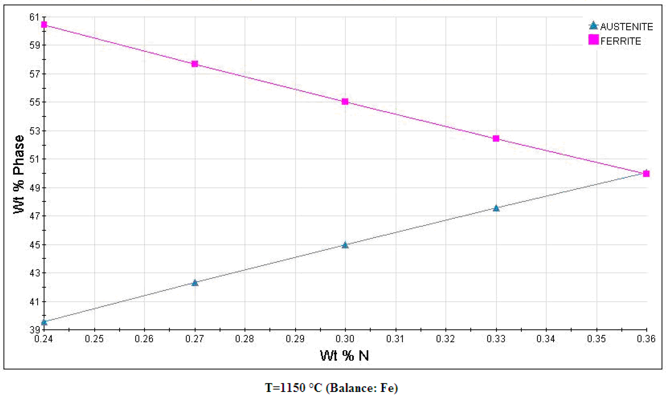
| Sample Number | The Content of Ferrite Phase/vol. % | Average Grain Size of Ferrite/µm | The Content of Austenite Phase/vol. % | Average Grain Size of Austenite/µm | The Content of Sigma Phase/vol. % | Average Grain Size of Sigma Phase/µm |
|---|---|---|---|---|---|---|
| S1 | 98.5 | 3.68 | 0.2 | 1.66 | - | - |
| S2 | 1.6 | 1.24 | 88.4 | 2.27 | 10.0 | 1.08 |
| S3 | 59.5 | 4.21 | 40.5 | 2.80 | - | - |
| S4 | 61.4 | 5.72 | 38.6 | 3.96 | - | - |
| S5 | 63.4 | 7.58 | 36.6 | 5.25 | - | - |
| Sample Number | Tensile Strength/MPa | Yield Strength/MPa | Elongation/% | Section Shrinkage/% | Impact Absorbing Energy/J | Hardness/HV |
|---|---|---|---|---|---|---|
| S1 | 1493 ± 6 | 1391 ± 9 | 13.2 ± 1 | 24.1 ± 3 | 18 ± 3 | 528.7 ± 4 |
| S2 | 593 ± 20 | - | - | - | - | 523.8 ± 8 |
| S3 | 941 ± 10 | 665 ± 7 | 24.6 ± 2 | 25.8 ± 3 | - | 321.8 ± 7 |
| S4 | 901 ± 4 | 658 ± 10 | 36.4 ± 2 | 48.4 ± 2 | 132 ± 5 | 291.5 ± 6 |
| S5 | 893 ± 1 | 646 ± 3 | 38.7 ± 2 | 52.6 ± 3 | - | 286.7 ± 5 |
| S6 | 851 ± 7 | 614 ± 10 | 29.2 ± 2 | 59.4 ± 3 | 128 ± 6 | 285.4 ± 4 |
| S7 | 920 (min) | 700 (min) | 25 (min) | - | - | 34 HRC (max) |
| Sample Number | Pitting Potential/mV |
|---|---|
| S1 | 1109 |
| S2 | 1055 |
| S3 | 1196 |
| S4 | 1109 |
| S5 | 1109 |
| Phase | Fe | Cr | Ni | Mo | N |
|---|---|---|---|---|---|
| α | 58.51 | 29.96 | 5.49 | 6.04 | 0.05 |
| γ | 59.41 | 25.81 | 9.78 | 5.00 | 0.52 |
© 2019 by the authors. Licensee MDPI, Basel, Switzerland. This article is an open access article distributed under the terms and conditions of the Creative Commons Attribution (CC BY) license (http://creativecommons.org/licenses/by/4.0/).
Share and Cite
Shang, F.; Chen, X.; Wang, Z.; Ji, Z.; Ming, F.; Ren, S.; Qu, X. The Microstructure, Mechanical Properties, and Corrosion Resistance of UNS S32707 Hyper-Duplex Stainless Steel Processed by Selective Laser Melting. Metals 2019, 9, 1012. https://doi.org/10.3390/met9091012
Shang F, Chen X, Wang Z, Ji Z, Ming F, Ren S, Qu X. The Microstructure, Mechanical Properties, and Corrosion Resistance of UNS S32707 Hyper-Duplex Stainless Steel Processed by Selective Laser Melting. Metals. 2019; 9(9):1012. https://doi.org/10.3390/met9091012
Chicago/Turabian StyleShang, Feng, Xiaoqiu Chen, Zhiyong Wang, Zuchun Ji, Fei Ming, Shubin Ren, and Xuanhui Qu. 2019. "The Microstructure, Mechanical Properties, and Corrosion Resistance of UNS S32707 Hyper-Duplex Stainless Steel Processed by Selective Laser Melting" Metals 9, no. 9: 1012. https://doi.org/10.3390/met9091012
APA StyleShang, F., Chen, X., Wang, Z., Ji, Z., Ming, F., Ren, S., & Qu, X. (2019). The Microstructure, Mechanical Properties, and Corrosion Resistance of UNS S32707 Hyper-Duplex Stainless Steel Processed by Selective Laser Melting. Metals, 9(9), 1012. https://doi.org/10.3390/met9091012