Article

The Research of Low-Oxygen Control and Oxygen Behavior during RH Process in Silicon-Deoxidization Bearing Steel

State Key Laboratory of Advanced Metallurgy, University of Science and Technology Beijing, Beijing 100083, China
*
Author to whom correspondence should be addressed.
Metals 2019, 9(8), 812; https://doi.org/10.3390/met9080812
Submission received: 26 June 2019 / Revised: 19 July 2019 / Accepted: 19 July 2019 / Published: 24 July 2019
(This article belongs to the Special Issue Bearing Steels)

Abstract

:
The variation of total oxygen (T.O) content, characterization of inclusions, slag composition, and off-gas behavior during the smelting process of silicon-deoxidization bearing steel were investigated with industrial experiments. The change of content of combined oxygen during RH (Ruhrstahl–Hereaeus vacuum degassing furnace) process was calculated and compared with T.O content change. It is found that the decrease of oxygen content is mainly caused by the removal of dissolved oxygen rather than the removal of oxides during RH process. Carbon was found to be a strong deoxidizer (stronger than aluminum) in high vacuum degree. Top slag is an oxygen source of the deoxidization process, leading to the re-oxidization of liquid steel, even though the FeO content is low in top slag. During the RH process, the change of oxygen mainly exists in three processes: 1) Deoxidization reaction in vacuum chamber, 2) oxygen mass transfer process between liquid steel out from a vacuum chamber and in ladle, and 3) oxygen mass transfer between ladle slag and liquid steel. It depends mainly on the mass transfer of the oxygen in the liquid steel.

1. Introduction

Bearing steel is often used for roller and ball bearings in engineering structures as bearing, for example, metallurgy, wind power, mining machinery, and aerospace [1]. The life of bearing is significant for security in engineering. However, non-metal inclusion as a kind of defect is one of the most important causes of life reduction of bearing [2,3,4]. In order to ensure the quality of bearing, there are two kinds of control conception: One controls the cleanliness of bearing steel, meaning very low total oxygen (T.O) content in the steel, and the other controls the type and morphology of inclusions by reducing inclusions unfavorable to fatigue life, such as TiN and large-sized calcium aluminate (Ca–Al–O) [5]. The first control conception is widely applied in the production of bearing steel and the T.O content can be controlled below 5 ppm, even 3–4 ppm, due to the development of production technology.
The production process for bearing steel is usually EAF (electric arc furnace)/BOF (basic oxygen furnace) → LF (ladle furnace) → VD (vacuum degasser) → CC (continuous casting) [6], where Al is used for deoxidization as a kind of strong deoxidizer and the oxygen content can be reduced to 3–4 ppm. However, in this production process, the controlling of the type and morphology of inclusions is difficult. Types of inclusions are mainly calcium aluminate (Ca–Al–O), spinal (Al–Mg–O), silicate (Si–Al–O), and a few TiN, in which calcium aluminate, spinal, and TiN are considered as the most hazardous to the fatigue life of bearing steel [7]. Recently, in order to control the type and morphology of inclusions—reducing the content of calcium aluminate and spinal—a kind of production method of bearing steel by using Si instead of Al as deoxidizer was put forward [8]. The production process is BOF → LF → RH (Ruhrstahl–Hereaeus) → CC. The main non-metal inclusion in the steel is silicate. The effect of the oxide inclusions generated in Si deoxidization on the fatigue life is lower than that in Al deoxidization, even if the T.O content is slightly higher. However, in this production process, the T.O content after the LF process is more than the Al deoxidization method because of the weak deoxidization ability of Si. In order to further deoxidization, the RH process is adopted to forced deoxidization to ensure the T.O content in the controlling range (less than 12 ppm).
In recent years, the RH process is gradually applied in the production of bearing steel instead of VD. The RH degassing furnace is vacuum refining equipment and commonly used in decarburization and degassing [9,10]. Due to the vacuum and intense stirring condition, the RH process is beneficial for low dissolved gas content and the removal of smaller inclusions because of more collision chance that can further reduce the T.O content in steel.
Much research has been conducted to understand the decarburization in the RH process. Some researchers [11,12,13,14,15] have established the model for prediction of decarburization reaction during the RH refining process. Liu [16] investigated the decarburization behaviors of ultra-low-carbon steel. The effects of the initial carbon content, initial oxygen content, and pressure in the vacuum chamber on decarburization rate were discussed and Liu found that enhancing the initial carbon content, the initial oxygen content, and reducing the pressure increased decarburization rate. However, when it comes to deoxidization in the RH process, it will be more complicated.
In this paper, the deoxidization process in bearing steel will be discussed. The bearing steel was produced by BOF→LF→RH→CC, and silicon was used for deoxidization after the converter tapping process. There was no deoxidizer added in the RH process. The T.O content after LF refining in the Si-deoxidization bearing steel was about 20–30 ppm, which was much higher than 15 ppm after LF refining in the Al-deoxidization bearing steel [8]. However, after deoxidization in the RH process and continuous casting, the T.O content in billets can be 8–10 ppm. Therefore, the aim of the current study is to clarify the low-oxygen control and oxygen behavior during the RH process in Si-deoxidization bearing steel. Both the industrial experiments and lab detection were conducted. The T.O content, characteristic of inclusions, composition of slag, and off-gas were obtained for further analysis. The relationship between smelting time and content of combined and dissolved oxygen was calculated to clarify the oxygen removal method. The reaction of [C] and [O] in the vacuum condition was discussed and the deoxidization abilities of several deoxidizer were compared to understand the deoxidization ability of carbon in the vacuum condition. Finally, the behavior of [O] during the RH process was obtained, which can be a guideline for Si-deoxidization bearing steel production to further control the T.O content in the steel.

2. Experimental

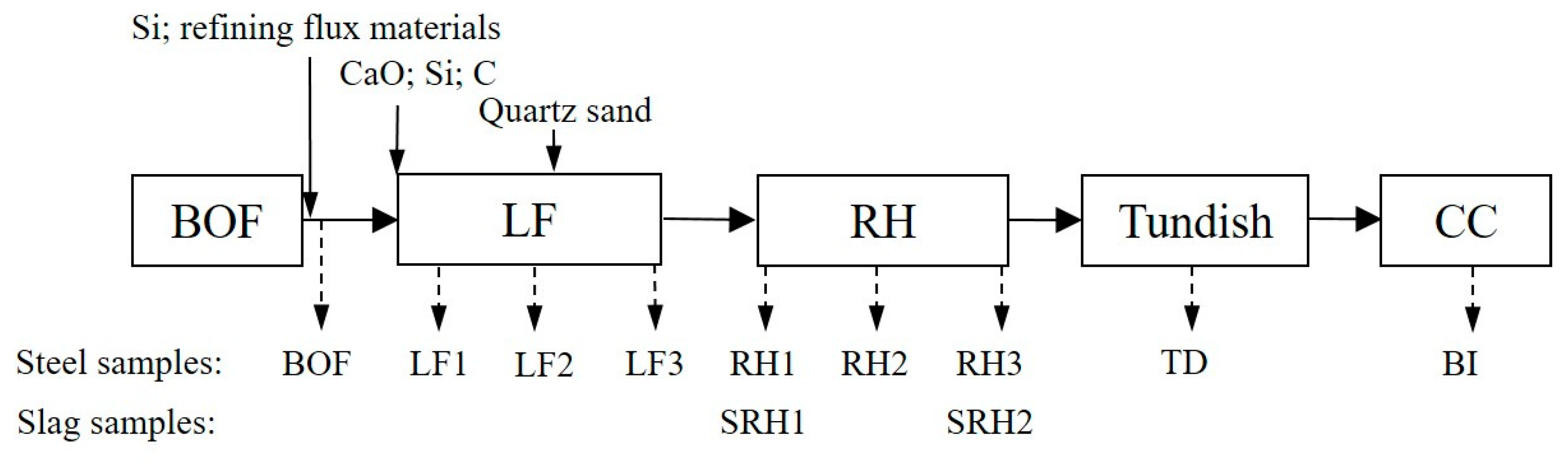
2.1. Production Process

In this steelmaking route, most sulphur was removed in KR (Kambara Reactor) pretreatment of hot metal. After BOF smelting, silicon was added to remove oxygen in the steel, and refining flux materials were added to slag during tapping process. At the beginning of the LF process, CaO was added to adjust the basicity of slag, carbon was added to adjust the carbon content in the steel, and silicon was added to reduce oxygen content. In the middle of LF refining, quartz sand was added to adjust the basicity of slag. Liquid steel was then processed with an RH degassing system for further removal of oxygen with no alloy addition. The ladle was finally shifted to the tundish for the continuous casting.
The chemical composition of the steel is listed in Table 1. The steelmaking route and sampling locations are shown in Figure 1.

2.2. Detection and Analysis Method

2.2.1. Inclusion and Slag Composition Detection

Steel samples were taken with pail-samplers (interior diameter 60 mm, height 100 mm): One after BOF smelting, three in the LF process, three in the RH process, and one in continuous casting, as shown in Figure 1. These samples were machined to rectangular pieces (10 mm × 10 mm × 10 mm), and polished for characterization of the inclusions by using an automatic inclusion analysis system (EVO18, Zeiss, Oberkochen, Germany) and scanning electron microscopy-energy dispersive spectroscopy (SEM-EDS). Cylinders (ϕ 5 mm × 50 mm) were machined for the measurement of the oxygen contents by the infrared absorption method. The compositions of the steel were determined by inductively coupled plasma atomic emission spectrometer.
Two slag samples in the RH process were taken out and ground to powder. The composition of the slag was analyzed by an X-ray fluorescence spectrometer.

2.2.2. Off-Gas Analysis

During the RH process, the off-gas flow rate was analyzed and the content of CO in the off-gas was monitored continuously by using an off-gas analysis system. The off-gas was taken from the tube continuously and sent to the off-gas analysis system, after removing dust and water, where its CO content was measured by infrared analyzer and its flow rate was measured by gas flowmeter.

3. Results

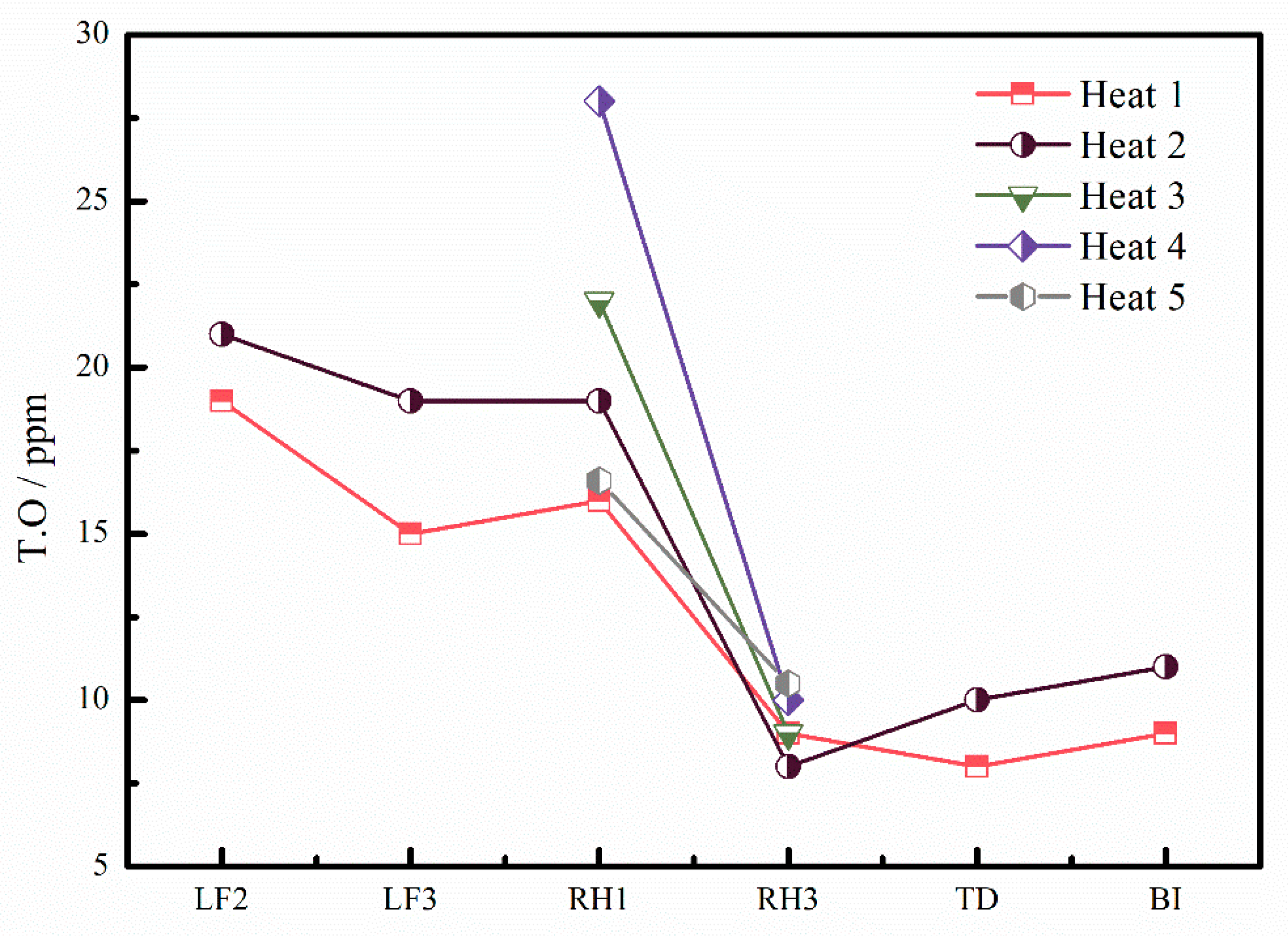
3.1. T.O Content Change

Figure 2 shows the changes in T.O during the whole smelting process. It can be read that T.O content was about 20 ppm at the beginning of the LF process and barely changed during the LF process. However, T.O content before the RH process was about 16–28 ppm, and rapidly decreased to 8–10 ppm at the end of the RH process, which means that 8–20 ppm oxygen was removed in the RH process. Although the T.O content before the RH process varied, the T.O content after the RH process reached the same low level.

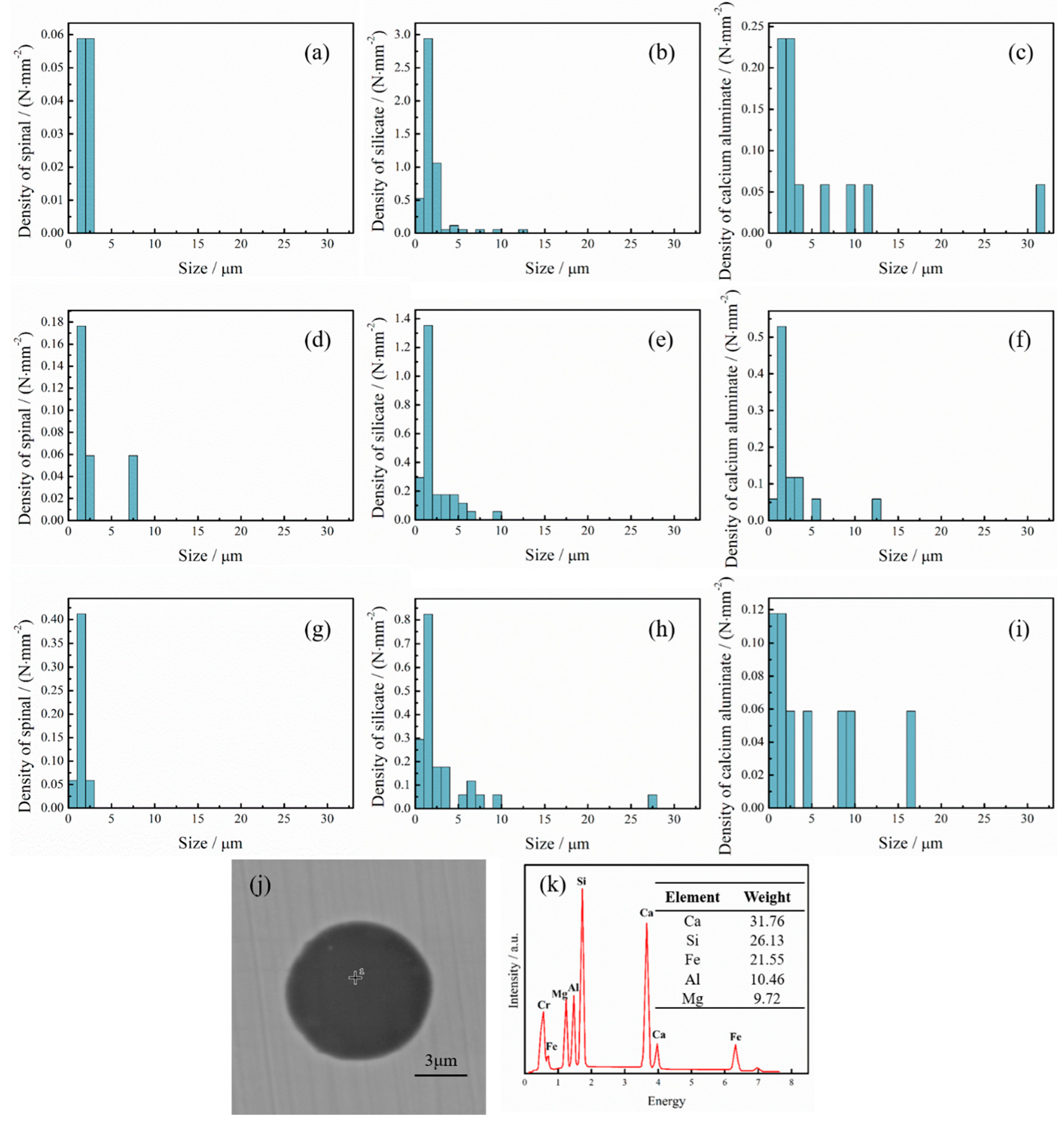
3.2. The Change of Oxides During RH Process

The main oxides in this steel are spinal, silicate, and calcium aluminate, where the content of silicate is the highest. The number density of the oxides indicates remarkable changes, and oxides of the size of 1–6 μm were effectively reduced as shown in Figure 3, where the number density of the silicate decreased while the number density of spinal and calcium aluminate increased. According to analysis, before the RH process was about 5.76 N/mm2, among which the number density of oxides smaller than 5 μm was about 5.35 N/mm2. After 10 min of treatment in RH, the number density of oxides decreased to 3.65 N/mm2 with the value of oxides smaller than 5 μm at about 3.24 N/mm2. About 23 min later, the number density of all detected oxides and those smaller than 5 μm decreased to 2.76 N/mm2 and 2.35 N/mm2, respectively.
It can be seen that RH has a strong ability to remove oxides from liquid steel. The small size oxides gathered and grew to oxides with bigger size. The bigger-size oxides floated and were captured by the slag layer, and were then removed due to the strong stirring in the RH process.
The microstructure of complex inclusion in the RH process is shown in Figure 3. In this Si-deoxidization steel, the Si content in the complex inclusion was more than Al content. However, in Al-deoxidization steel, the Al content in the complex inclusion was more than Si content [8]. This inclusion with more Si content had less effect on the fatigue life of bearing steel.

3.3. Change of FeO Content in Refining Slag

The compositions of top slag before and after the RH process were analyzed and the results are shown in Table 2. The basicity of the slags (R) were nearly kept the same value during the RH process. The main change of compositions were FeO and MnO, where the content of FeO decreased by 0.441 wt% and the content of MnO increased by 0.023 wt%.

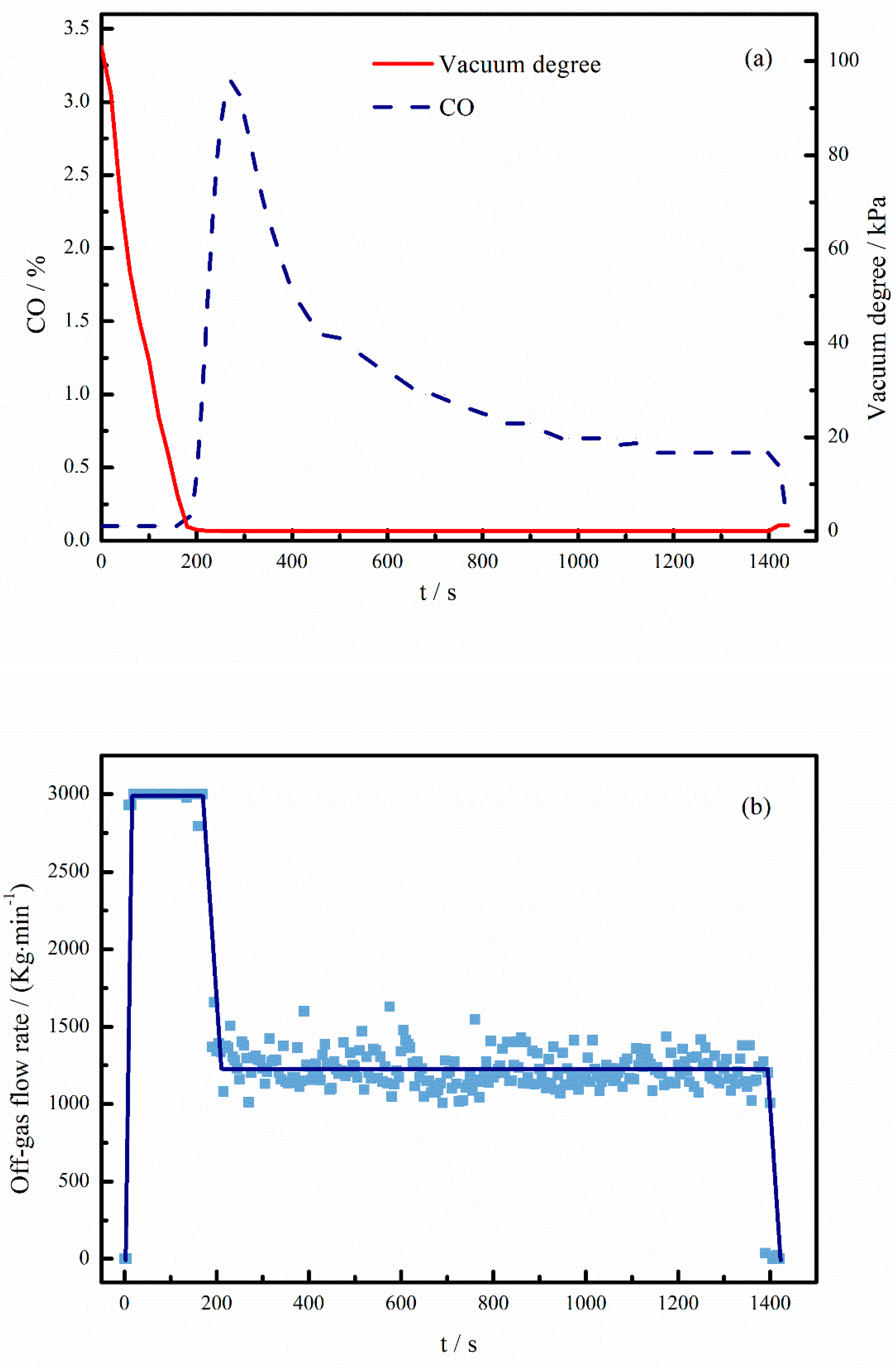
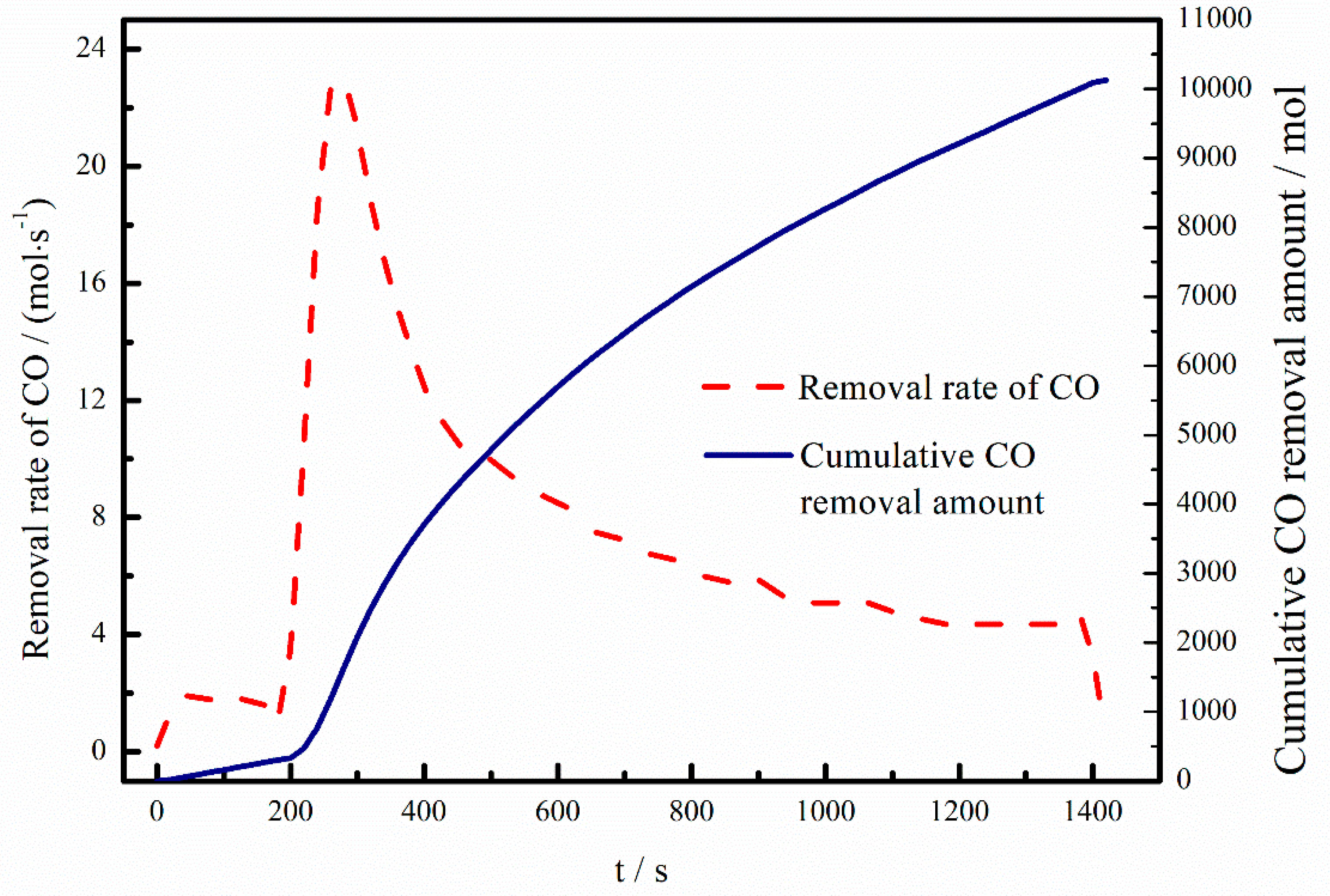
3.4. Component Analysis of Off-Gas

Figure 4a shows the variation of the pressure in the RH vacuum chamber and the CO content in the off-gas during the RH process. It can be seen that the pressure of the RH vacuum chamber decreased to about 1000 Pa at 180 s and directly decreased to ultimate vacuum degree without a pressure drop platform while the CO concentration rapidly increased to the peak of about 3.25% within 100 s and subsequently decreased to a certain value where the final operation time as 23 min. Figure 4b shows the off-gas flow rate during the RH process. During the period of vacuum decreasing, the off-gas flow rate reached the peak value and was kept steady for about 3 min. Subsequently, it dropped to a relatively steady value rapidly until the end of the RH process.

4. Discussion

4.1. The Relationship of Smelting Time and Content of Combined and Dissolved Oxygen

From the results, the diameters of oxides are mainly in a range of 0.5 to 5 μm in the steel while the types of oxides are mainly silicate, spinal, and calcium aluminate. Detailed data were obtained by an automatic inclusion analysis system, and the number of oxides per unit area was calculated according to these detected data. In order to evaluate the oxygen content existing as oxides in the steel, it was calculated by Equations (1)–(4) [17], in which DeHoff’s formulas were expressed by Equations (1) and (2), the volume fraction of oxides was calculated by Equation (3), and the oxygen content existing as oxides in the steel was calculated by Equation (4).
N V = 2 π N a d ¯ ,
1 d ¯ = 1 n 1 d i ,
V = π 6 d 3 N V ,
[ O ] ox = ( ρ ox ρ Fe ) · V · ( O ) ox ,
where NV is the number of oxides per unit volume in specimen, m−3; Na is the number of oxides per unit area in specimen, m−2; di is apparent particle size of i-th oxide among n oxides, m; d ¯ is harmonic mean of oxide particle size, m; V is volume fraction of oxides; [ O ] ox is the oxygen content existing as oxides in the steel; ρox is the oxide density, kg∙m−3; ρFe is steel density, kg∙m−3; ( O ) ox is the oxygen content of oxides.
The change of the oxygen content existing as oxides and dissolved oxygen in the steel is shown in Figure 5. At the beginning of the RH process, the oxygen content existing as oxides in the steel was about 3 ppm and decreased to 1.4 ppm after 10 min of treatment in RH. When the treatment time reached 23 min, the oxygen content existing as oxides in the steel barely changed. However, the change of the oxygen content existing as oxides in the steel at the beginning and end of the RH process was about 1.7 ppm, which is much smaller than the change of the T.O content before and at the end of the RH process, which was 10–20 ppm. Thus, most of the oxygen in the steel was not removed by the removal of oxides, but due to the removal of dissolved oxygen during the RH process.

4.2. Carbon Deoxidization during the RH Process

In order to explain the removal of dissolved oxygen in steel, the component of off-gas was detected. The existence of CO in off-gas in Figure 4 indicates that there is a C–O reaction that occurred in the RH process. However, the small peak value of CO concentration indicates a weak C–O reaction during the RH process, which is caused by the very low content of dissolved oxygen in the liquid steel.

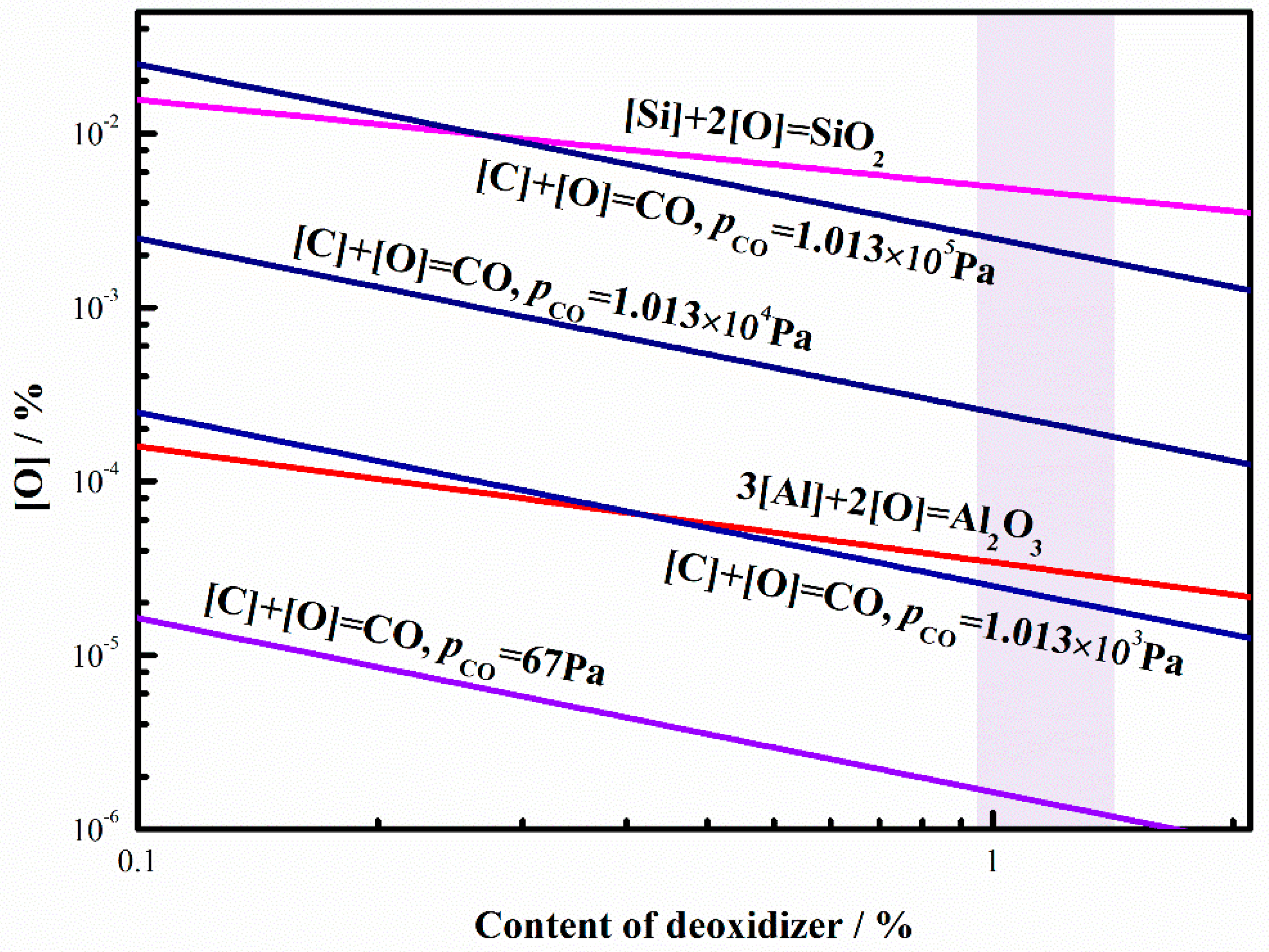
4.2.1. The Deoxidization Ability of Carbon during Different Vacuum Condition

Oxides were partly removed due to the agitation and dissolved oxygen reacting with carbon in the liquid steel where its reaction product, CO, was exhausted out of the RH system to remove oxygen from liquid steel during the RH process. According to the detected results, it can be found that the main oxidization process was the reaction of dissolved oxygen with carbon when there was high carbon content in the steel during the RH process. The C–O equilibrium and deoxidization ability of the RH process in high-carbon steel will be discussed here.
During the RH process, the deoxidization reactions can be represented by
[C] + [O] = CO (g),
GѲ = −2364 − 39.63T,
where ∆GѲ is the standard Gibbs free energy, J/mol; and T is the temperature, K.
The equilibrium constant K is expressed by
K = P CO a C · a O = P CO f C · f O · [ C % ] [ O % ] ,
where PCO is the partial pressure of CO, Pa; aC is the activity of element C in the liquid steel; aC is the activity of element O in the liquid steel; [C%] is the mass fraction of element C in the liquid steel; [O%] is the mass fraction of element O in the liquid steel; fC and fO are the activity coefficients of elements C and O in the liquid steel, respectively.
When the concentration of carbon is 0.02–2wt%, fC and fO can be approximately equal to 1. Thus, Equation (7) can be expressed by
K = P CO a C · a O = P CO [ C % ] [ O % ] .
When T = 1873 K, there is
[ C % ] [ O % ] = 0.0025 P CO .
Extra carbon in liquid steel can react with oxygen and CO as the reaction product will be exhausted out of the vacuum chamber during the RH process. It means that carbon becomes deoxidizer in a vacuum environment and its deoxidization ability increases with the increase of vacuum degree.
Figure 6 shows the equilibriums of [C], [Al], [Si], and [O] in liquid steel at 1873 K during different vacuum degrees. The reaction of [Al] and [O] can be expressed by
2[Al] + 3[O] = Al2O3(s),
GѲ = –1,218,799 + 394.13T.
The reaction of [Si] and [O] can be expressed by
[Si] + 2[O] = SiO2(s),
GѲ = –594,285 + 229.76T.
Considering fAl = fSi = fO = 1, and when T = 1873 K, there are
[ Al % ] [ O % ] 1.5 = 2.00 × 10 7 ,
[ Si % ] [ O % ] 2 = 2.45 × 10 5 .
It can be seen from Figure 6 that the content of deoxidizer in liquid steel determined the oxygen content in liquid steel when the reaction reached equilibrium, where the oxygen content was less when the content of deoxidizer was more. The deoxidization ability of aluminum, which is a kind of strong deoxidizer, was obviously better than the deoxidization ability of Si. When it comes to C, its deoxidization ability was related to the value of PCO, or vacuum degree in the RH process. When the vacuum degree was less than 1.013 × 10⁴ Pa, the deoxidization capability of carbon was better than silicon; when the vacuum degree reached 67 Pa, the deoxidization capability of carbon was even better than aluminum. As for this high-carbon steel, of which carbon content is about 1 wt%, the oxygen content in liquid steel can even reach to 10−6 wt%.
However, the T.O content at the end of the RH process, which was measured from pail-samplers, is 8–10 ppm, which is much more than 10−6 wt%. The reasons might be (1) the small content of oxygen reacted with carbon, leading to the remaining oxygen content, and (2) the existence of other oxygen source and transfer oxygen to liquid steel.
In Figure 4, it can be seen that the flow rate remained stable when the vacuum chamber reached minimal value and the removal rate of CO (vRCO, mol/s) can be calculated by the off-gas flow rate and CO content (CO%) in the off-gas, shown in Figure 7. The removal weight of oxygen (wRO, ppm) can be expressed by
w RO = 16 0 t v RCO d t w steel ,
where wsteel is the weight of steel in ladle, 1.2 × 10⁸ g; 0 t v RCO d t is the cumulative CO removal amount, 10,132 mol.
The calculated removal weight of oxygen is 1351 ppm, which is much more than the T.O content in the steel, meaning that there is no possibility of reason (1). Thus, the existence of other oxygen source should be discussed.

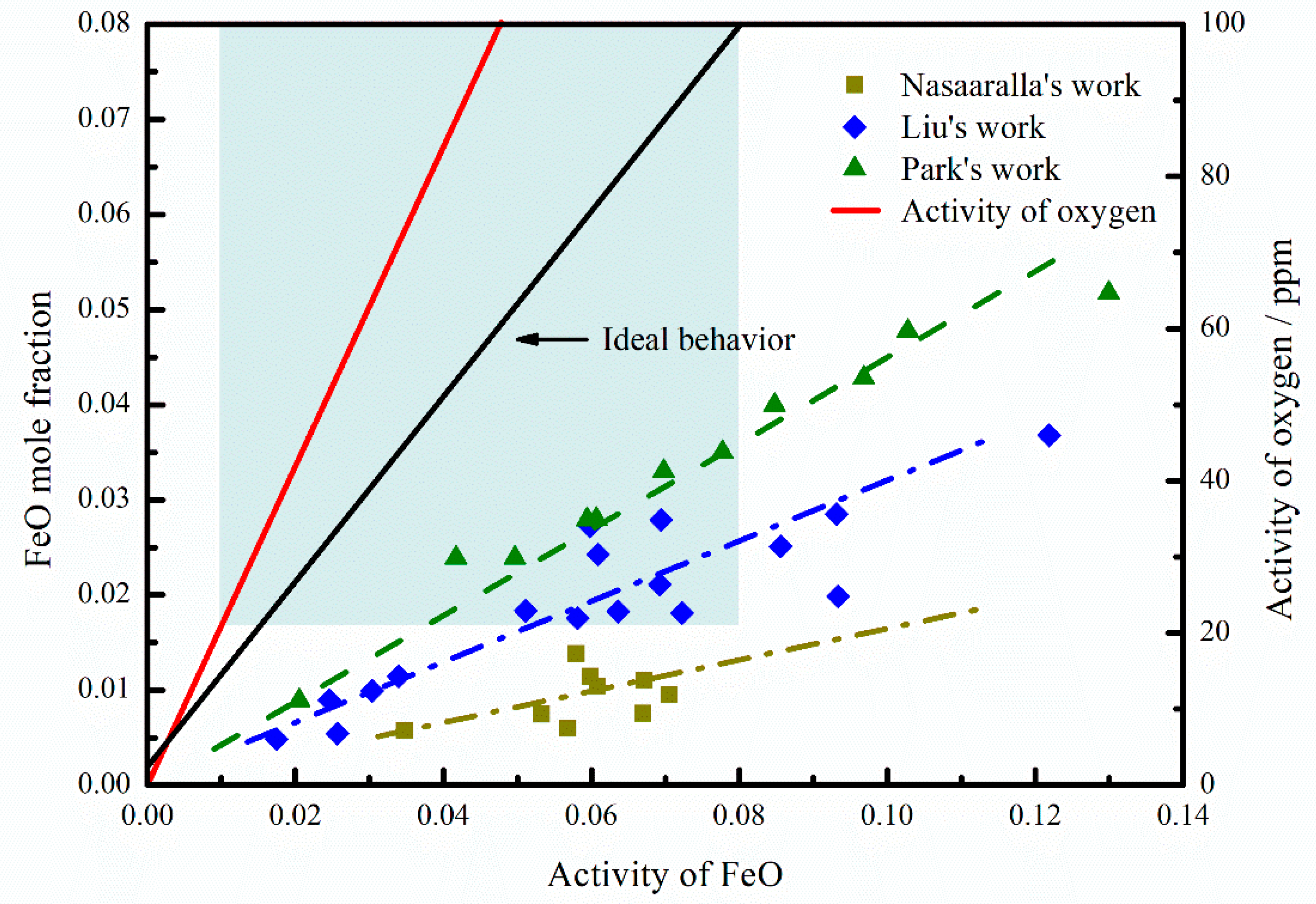
4.2.2. Effect of Oxidizing RH Slag on Deoxidization

Usually, the cleanliness of steel is significantly affected by the composition of top slag, especially the w(FeO) in the top slag during the RH process that affects the T.O content. In order to consider the existence of other oxygen source, the top slag is considered as the most possible source [18]. w(FeO) is the index to evaluate the oxidability of slag. When w(FeO) is more, the oxidability of slag is higher and the liquid steel is easier to be oxidized, which will result in the deterioration of cleanliness of steel.
In the RH process, the following reactions will occur between top slag and steel.
(FeO) = [O] + [Fe],
x[M] + y[O] = (MxOy).
Oxygen will get into the liquid steel and oxidize elements through these reactions. Thus, T.O content in steel will increase. It can be seen from Table 2 that most components of the top slag were unchanged, while w(FeO) decreased 0.441 wt% indicating that Equations (17) and (18) occurred and the oxygen entering the liquid steel led to the re-oxidization of liquid steel.
The equilibrium relationship between FeO and liquid steel can be expressed as Equation (17). The equilibrium constants K and ∆GѲ are expressed by
K = a [ O ] · a [ Fe ] a FeO ,
GѲ = 117,733.7 − 49.85T.
According to Equation (19), the activity of dissolved oxygen is related to the activity of [Fe] and FeO in slag at a certain temperature. However, in the bulk of liquid steel, the activity of [Fe] can be considered as 1. Thus, the activity of dissolved oxygen is only related to the activity of FeO in slag at a certain temperature. According to the thermodynamic data of Equation (20), the relationship between the activity of FeO and the activity of oxygen can be calculated as shown in Figure 8. As shown in Table 2, there was 0.9%–1.4% FeO in refining slag, while the w(FeO) in slag is usually in the range of 0.5–1.5 wt% meaning the mole fraction of FeO is in the range of 0.0044–0.013.
Some scholars [19,20] have investigated the activity of FeO in slag when the basicity of slag is 0.8–1.3, as shown in Figure 8. When the mole fraction of FeO is in the range of 0.0044–0.013, the activity values is in the range of 0.01–0.08. Thus, it can be seen in Figure 8 that when the activity of FeO was 0.01, the activity of oxygen was 21 ppm and it increased with the increase of the mole fraction of FeO, indicating that the activity of oxygen was more than 21 ppm in this paper. However, the activity of dissolved oxygen in liquid steel was less than 10 ppm according to detected results, which is much smaller than the oxygen controlled by the equilibrium relationship between FeO and liquid steel. Therefore, the top slag would be the source of oxygen and transfer the oxygen into liquid steel.

4.3. Behavior of [O] during RH Process

In the RH process, the change of oxygen mainly exists in three processes, as shown in Figure 9a: (1) Deoxidization reaction and the removal of CO(g) in a vacuum chamber, (2) oxygen mass transfer process between liquid steel out from a vacuum chamber and in ladle, and (3) oxygen mass transfer between ladle slag and liquid steel.
(1)
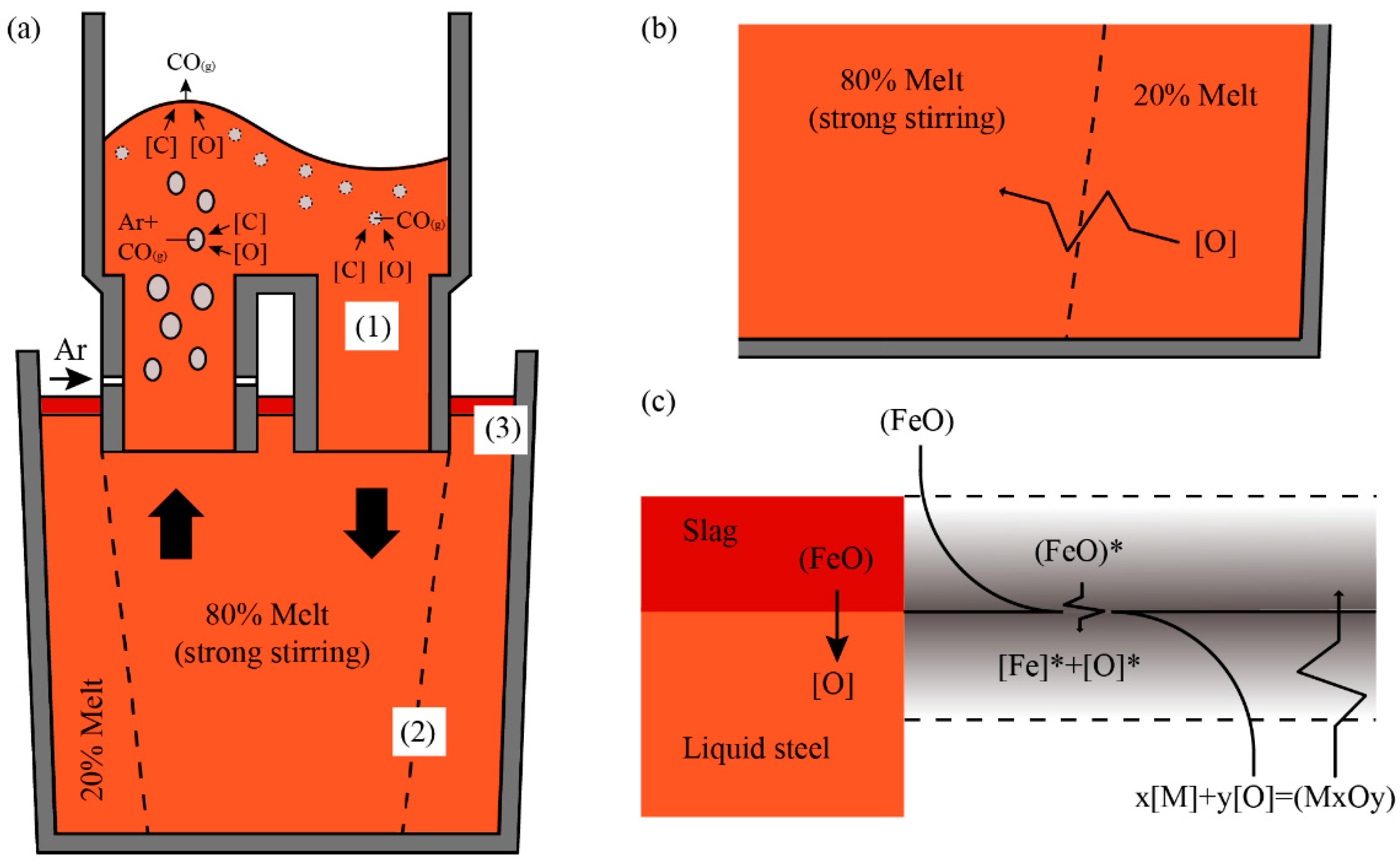
Deoxidization reaction mainly takes place in a vacuum chamber that involves the following three reaction sites: (a) Spontaneous CO bubbles formed in the bulk steel; (b) Ar bubbles from the Ar blowing in the upper snorkel; (c) bath surface exposed in the ultra-low-pressure environment. The reaction product, CO (g), will be exhausted due to the vacuum condition promoting the reaction.
(2)
There is part of the liquid steel in the ladle that is nearly immobile when the circulation of RH agitates liquid steel, which is called the dead zone in ladle. The oxygen content of the liquid steel out from the vacuum chamber is relatively lower than that in the dead zone in the ladle because of the deoxidization reaction that occurred in the vacuum chamber. The gradient of oxygen results in the oxygen mass transfer between dead zone and stirring zone.
(3)
The oxygen in the slag significantly affects the deoxidization effect in the RH process as explained above. The oxygen mass transfer between the ladle slag and liquid steel mainly occurred due to the reactions of Equations (17) and (18). Some researchers [21] used double-film theory to explain the re-oxidization process, which is shown in Figure 9c. According to the theory, the activity of oxygen at the boundary layer depends on the Fe–O equilibrium at the steel slag interface, while the concentration of oxygen in liquid steel depends on the M–O equilibrium. The M–O equilibrium cannot be established because of the deoxidization of RH process with the vacuum condition. Thus, a new M–O equilibrium can be established only when [M] in steel reacts with O in slag continuously, which results in the mass transfer of oxygen from ladle slag to liquid steel.
In the RH process, the change of oxygen, including the deoxidization rate, mainly depends on the mass transfer of the carbon and oxygen in the liquid steel. It has been reported [11] that the value of [C]/[O] affects the rate-determining step of mass transfer. While the [C] content in the steel is about 1wt% and the [O] content is about 20~30 ppm after the LF refining process, the value of [C]/[O] in the steel is much more than 0.52. Thus, the mass transfer of the oxygen in the liquid steel is the rate-determining step.
At the beginning of RH, as the pressure in the vacuum chamber decreased, the C–O reaction started in the vacuum chamber, and the oxygen content of the liquid steel in the vacuum chamber kept decreasing. The liquid steel with low-oxygen content in the vacuum chamber entered the ladle as the flow cycle progressed. Compared with the dead zone, the oxygen content in the stirring zone was lower, forming a concentration gradient of oxygen and causing oxygen to transfer from the dead zone to the stirring zone. At the same time, the top slag kept transmitting oxygen to the liquid steel as described above. Due to the strong agitation of the RH process, the mass transfer of oxygen in the liquid steel was accelerated, and the oxygen at the slag–steel interface was continuously diffused to the low-oxygen-content zone, which accelerates the oxygen transfer process from the slag to the liquid steel.
In the initial stage of the C–O reaction, oxygen in the liquid steel was the main source of oxygen in the reaction. At this time, oxygen mass transfer in the liquid steel was the rate-determining step. The stirring in the RH process greatly accelerated the mass transfer of oxygen. Thus, the reaction rate was fast at the beginning of RH, and the CO content in the off-gas rapidly increased. When the C–O reaction proceeded to a certain extent, the oxygen content in the liquid steel in the stirring zone was significantly reduced, and the reaction rate was significantly reduced. At this time, the oxygen mass transfer in the slag–steel interface became the rate-determining step of the removal of oxygen.

5. Conclusions

Industrial experiments were carried out to investigate the deoxidization in the RH process of GCr15 bearing steel. T.O and characterization of inclusions in whole smelting process, slag composition, and off-gas during RH process were investigated. The following conclusions were obtained:
(1)
The content change of the combined oxygen during the RH process was calculated. Compared with the change of T.O, it is found that the decrease of the oxygen content is not mainly caused by the removal of oxides, but caused by the removal of dissolved oxygen during RH process.
(2)
Carbon deoxidization exists in the RH process in high-carbon steel with low oxygen content, and carbon is found to be a strong deoxidizer. In high vacuum degree, the deoxidizing capacity of carbon is even stronger than Al.
(3)
The oxygen is transferred from the top slag to the liquid steel during the deoxidization process, leading to the re-oxidization of liquid steel despite the low FeO content in top slag.
(4)
During the RH process, the change of the oxygen content mainly exists in three processes: 1) Deoxidization reaction in the vacuum chamber, 2) oxygen mass transfer process between liquid steel out from the vacuum chamber and in the ladle, and 3) oxygen mass transfer between the ladle slag and liquid steel. The changes in the oxygen content mainly depends on the mass transfer of the oxygen in the liquid steel.

Author Contributions

Data curation, W.X.; writing—original draft preparation, W.X.; writing—review and editing, W.X., M.W. and Y.B.; supervision, Y.B.

Funding

This research was funded by the State Key Laboratory for Advanced Metallurgy Foundation (No. 41618030).

Conflicts of Interest

The authors declare no conflict of interest.

References

  1. Wang, S.; Lv, Q.; Wang, H.; Liang, M. Behavior of non-metallic inclusions in casting slab of bof bearing steel. J. Southeast Univ. Nat. Sci. Ed. 2006, 27, 192–195. [Google Scholar]
  2. Walker, P.F.F. Improving the reliability of highly loaded rolling bearings: The effect of upstream processing on inclusions. Mater. Sci. Tech.-Lond. 2014, 30, 385–410. [Google Scholar] [CrossRef]
  3. Kamiya, T.; Mizobe, K.; Kida, K. Effect of observation position of SUJ2 bar specimens on inclusions distribution. IOP Conf. Ser. Mater. Sci. Eng. 2018, 307, 012046. [Google Scholar] [CrossRef]
  4. Gu, C.; Bao, Y.; Gan, P.; Wang, M.; He, J. Effect of main inclusions on crack initiation in bearing steel in the very high cycle fatigue regime. Int. J. Min. Met. Mater. 2018, 25, 623–629. [Google Scholar] [CrossRef]
  5. Liu, L. New tendency and process innovation for special steels. Steelmaking 2017, 33, 1–11. [Google Scholar]
  6. Ma, W.J.; Lui, G.L.; Gao, P.; Luo, Y.Z.; Li, H.B.; Chen, B. Study on controlling inclusions and total oxygen of high-carbon steel. Mater. Sci. Tech.-Lond. 2016, 32, 1119–1125. [Google Scholar] [CrossRef]
  7. Li, M.; Wang, X.; Duan, J.; Yang, W. Formation and controlling of type-D inclusions in bearing steel. Chin. J. Eng. 2018, 40, 31–35. [Google Scholar]
  8. Gu, C.; Bao, Y.; Gan, P.; Lian, J.; Münstermann, S. An experimental study on the impact of deoxidation methods on the fatigue properties of bearing steels. Steel Res. Int. 2018, 89, 1800129. [Google Scholar] [CrossRef]
  9. Geng, D.; Lei, H.; He, J. Numerical simulation of the multiphase flow in the Rheinsahl–Heraeus (RH) system. Metall. Mater. Trans. B 2010, 41, 234–247. [Google Scholar] [CrossRef]
  10. Wang, M.; Bao, Y.; Zhao, L.; Yang, Q.; Lin, L. Difference analysis in steel cleanness between two RH treatment modes for SPHC grade. ISIJ Int. 2015, 55, 1652–1660. [Google Scholar] [CrossRef]
  11. Ling, H.; Zhang, L. A mathematical model for prediction of carbon concentration during RH refining process. Metall. Mater. Trans. B 2018, 49, 2963–2968. [Google Scholar] [CrossRef]
  12. Van Ende, M.; Kim, Y.; Cho, M.; Choi, J.; Jung, I. A kinetic model for the Ruhrstahl-Heraeus (RH) degassing process. Metall. Mater. Trans. B 2011, 42, 477–489. [Google Scholar] [CrossRef]
  13. Ling, H.; Zhang, L. Investigation on the fluid flow and decarburization process in the RH process. Metall. Mater. Trans. B 2018, 49, 2709–2721. [Google Scholar] [CrossRef]
  14. Kuwabara, T.; Umezawa, K.; Mori, K.; Watanabe, H. Investigation of decarburization behavior in RH-reactor and its operation improvement. Trans. Iron Steel Inst. Jpn. 1988, 28, 305–314. [Google Scholar] [CrossRef]
  15. Yamaguchi, K.; Kishimoto, Y.; Sakuraya, T.; Fujii, T.; Aratani, M.; Nishikawa, H. Effect of refining conditions for ultra low carbon steel on decarburization reaction in RH degasser. ISIJ Int. 1992, 32, 126–135. [Google Scholar] [CrossRef]
  16. Liu, B.; Zhu, G.; Li, H.; Li, B.; Cui, Y.; Cui, A. Decarburization rate of RH refining for ultra low carbon steel. Int. J. Min. Met. Mater. 2010, 17, 22–27. [Google Scholar] [CrossRef]
  17. Wang, M.; Bao, Y.; Cui, H.; Wu, H.; Wu, W. The composition and morphology evolution of oxide inclusions in Ti-bearing ultra low-carbon steel melt refined in the RH process. ISIJ Int. 2010, 50, 1606–1611. [Google Scholar] [CrossRef]
  18. Kim, S.; Song, B. Thermodynamic aspects of steel reoxidation behavior by the ladle slag system of CaO-MgO-SiO2-Al2O3-FetO-MnO-P2O5. Metall. Mater. Trans. B 1999, 30, 435–442. [Google Scholar] [CrossRef]
  19. Liu, S.; Fruehan, R.J.; Morales, A.; Ozturk, B. Measurement of FeO activity and solubility of MgO in smelting slags. Metall. Mater. Trans. B 2001, 32, 31–36. [Google Scholar] [CrossRef]
  20. Deng, Z.; Zhu, M. Deoxidation mechanism of Al-killed steel during industrial refining process. ISIJ Int. 2014, 54, 1498–1506. [Google Scholar] [CrossRef]
  21. Qin, Y.; Wang, X.; Li, L.; Huang, F. Effect of oxidizing slag on cleanliness of if steel during ladle holding process. Steel Res. Int. 2015, 86, 1037–1045. [Google Scholar] [CrossRef]
Figure 1. Process of industrial trials and sampling locations.
Metals 09 00812 g001
Figure 2. Change of total oxygen (T.O) content in the steel.
Metals 09 00812 g002
Figure 3. Changes in number density and size distribution of oxide inclusions during Ruhrstahl–Hereaeus (RH) treatment: (a) Spinal, (b) silicon, and (c) calcium aluminate inclusions before treatment; (d) spinal, (e) silicon, and (f) calcium aluminate inclusions after being treated for 10 min; and (g) spinal, (h) silicon, and (i) calcium aluminate inclusions after being treated for 23 min; (j) SEM and (k) EDS results of inclusion in the RH process.
Metals 09 00812 g003
Figure 4. Variation in pressure of the RH vacuum chamber and CO content in the off-gas (a), off-gas flow rate of (b) during the RH process.
Metals 09 00812 g004
Figure 5. Change of the content of oxygen existing as oxides and dissolved oxygen in the steel.
Metals 09 00812 g005
Figure 6. The equilibriums of [C], [Al], [Si], and [O] in liquid steel at 1600 °C during different vacuum degrees.
Metals 09 00812 g006
Figure 7. Removal rate of CO and cumulative CO removal amount.
Metals 09 00812 g007
Figure 8. Relationship between activity of FeO and activity of oxygen and FeO content in the CaO–SiO2–Al2O3–FeO–MgOsat slag system (B = 0.8 to 1.3 and T = 1823 to 1873 K), data from [19].
Metals 09 00812 g008
Figure 9. (a) Schematic drawing of the reaction mechanisms of the decarburization process in the RH; (b) oxygen mass transfer from dead zone to stirring area in the ladle; (c) double film theory: The mass transfer from (FeO) to [O].
Metals 09 00812 g009
Table 1. Compositions of the silicon-deoxidization bearing steel (wt%).
ComponentT.OCSiCrMnPSAl
Concentration0.000810.271.380.350.0150.00650.002
Table 2. The composition of top slag (wt%).
StageCaOSiO2Al2O3MgOFeOMnOR
SRH137.241.74.6712.51.3860.8591.072
SRH237.641.84.7612.40.9450.8821.074
Note: R = w(CaO + MgO)/w(SiO2 + Al2O3).

