Abstract
Friction stir lap welding (FSLW) of 6061-T6 aluminium sheet and DX51D galvanized steel sheet was carried out by adding zinc foil to the lap interface and studying the influence of the zinc foil on the formation mechanisms and mechanical properties. The influence of the thickness of zinc foil, the plunge depth of the shoulder and the shape of the tools on the mechanical properties of the weld are discussed. Zinc foil reduced the generation of brittle intermetallic compounds, such as Fe4Al13. During the welding process, the axial force was small due to the high rotating speed. Liquid zinc was retained at the interface, where eutectic Al–Zn with low melting point and an Fe–Zn compound were generated to achieve the metallurgical combination of aluminium and steel. The fracture was located in the heat affected zone (HAZ) of the 6061-T6 base aluminium. The results showed that when the zinc foil was too thin, there was less zinc content at the interface; the resulting Al–Zn eutectic had low melting point, was not fully spread and had poor continuity, resulting in poor mechanical properties. When the zinc foil was too thick, a large amount of zinc-based solid solution was generated at the interface, and most of the fracture occurred in the zinc-rich layer.
1. Introduction
Aluminium–steel lap members have both the high strength from steel and the high specific strength from the aluminium. These materials are widely used in vehicle manufacturing [1]. The metal welding types for aluminium–steel joints mainly include fusion welding, non-fusion welding and mechanical connection. Although the heat input in the welding process can be controlled by TIG (Tungsten Inert Gas) welding and MIG (Metal Inert Gas) welding, due to the great difference in properties between aluminium and steel, it is still easy to have problems with the quality of the welding seams, such as porosity, cracks and droplet spatter [2]. When the size requirement of the component is small, it can be connected by brazing. However, the strength is low, and the joining position is specific. The process is difficult to control, which is not conducive to mass production. If riveting is used to connect aluminium and steel, holes are required, which is a cumbersome process that reduces efficiency, and rivets also increase the weight of the components and necessary overlap.
Compared with aluminium sheet and steel sheet welding, friction stir welding has advantages. Friction stir welding (FSW) is a new solid phase welding technology invented by The Welding Institute in 1991. Friction stir welding does not require protective gas. There is no arc radiation, smoke, splash and other pollution in the welding process, and it is known as a “green welding method” [3]. Compared with traditional fusion welding, welding defects, such as cracks, porosity, and vaporization of alloying elements during friction stir welding, are greatly reduced or even non-existent [4,5,6,7].
What affects the welding performance is the length of the pin, the plunge depth of the shoulder and the welding speed in friction stir welding of aluminium and other metals. Elrefaey [8] carried out lap welding tests on 2.0 mm thick aluminium plates and 1.2 mm thick mild steel at speeds lower than 100 rpm and found that the mechanical properties of joints obtained by welding when the pin was slightly inserted into the lower steel plate were superior to those obtained by welding when the pin was not inserted below the aluminium–steel interface at all. However, the pin was depleted during the welding process, and the welding process was less repeatable. Das H and Pal T K. et al. [9] carried out friction stir lap welding with a 2.5 mm long pin on 6061-T6 plate and coated steel steel plate with 1 mm thickness. They found that the mechanical properties of the joints increased first and then decreased when the welding speed increased within certain range.
Al/Fe intermetallic compounds are produced in the lap welding process of aluminium sheets and galvanized steel sheets, and the intermetallic compounds (IMC) organizational characteristics and morphology affect the joint performance. Yingchun Chen, T. Komazaki et al. used a welding tool with a 2.8mm pin and a shoulder diameter of 15.0 mm to realize the lap friction stir welding of a 3.0 mm AC4C aluminium plate and a 0.8 mm hot dipped galvanized steel plate. The zinc coating played a key role in the friction stir welding lap joint of aluminium and steel. The study also found that the rotational speed of the welding tool and welding speed simultaneously affected the thickness of the IMC and determined the microstructure, mechanical properties and fracture location of welded joints. At the same welding speed, the IMC thickness decreased with the increase of the rotating speed of the welding tool, resulting in an increase of tensile fracture load with an increase of welding speed [10]. Zhang G et al. selected a welding tool with a shaft shoulder diameter of 20.0 mm, welded aluminium and stainless-steel plates with thicknesses of 1.8 mm by means of multi-pass friction stir welding, and formed a micron-thick diffusion layer at the lap interface [11]. Y.C. Chen et al. systematically studied the effects of different surface morphologies of steel on the interfacial friction stir welding interface structure of aluminium and steel, pointing out the three different types of steel surfaces (galvanized steel, brushed steel and mirror-treated steel). The combination and the mechanical properties of the welded joint of galvanized steel and AC4C alloy was the best of the samples considered in the study, which was 5.02 kN [12]. Y.C. Chen et al. believed that the zinc foil that was subjected to high temperature melting during the welding process helped to remove surface oxides and oil stains at the interface of the aluminium and steel, thereby promoting atomic diffusion at the aluminium–steel interface to form Fe2Al5 and Fe4Al13 intermetallic compounds [13]. Through friction stir welding of 5083 aluminium and SS400 steel, Kimapong and Watanabe et al. found that with the increase of the inclination of the pin, Al5Fe and other intermetallic compounds were generated on the aluminium–steel interface, which increased the mechanical properties of the welded joint [14,15].
However, the above research used a conventional rotation speed for welding. To obtain enough energy, a large shoulder, plunge depth or large axial force [16] is required. Therefore, in the above study, the thickness of the aluminium plate is mostly 2.0 mm or more, otherwise the sheet will be seriously deformed. If the same method is used to weld the thin plate, the larger plunge depth causes the workpiece to be thinner, and the larger axial force and heat generation also causes welding deformation. If the welding is carried out with a smaller shoulder, there is insufficient heat production under normal speed conditions, so high-speed welding becomes a valuable option. During the friction stir welding of the 2014 aluminium sheet, Chen S. et al. [17] found that the rotational speed was in the range of 10000 rpm to 16500 rpm, and the axial force during the welding stage was less than 200 N. High speed is an effective way to reduce the axial pressure and is more conducive to the sheet. However, when the sheet was welded, there were still problems, such as the occurrence of intermetallic compounds at the aluminium–steel interface, resulting in poor mechanical properties of the joint. Therefore, it is especially necessary to study processes that avoid the formation of intermetallic compounds at the aluminium–steel interface but still enable them to be effectively joined. An intermediate layer transition metal is needed to prevent direct contact of the aluminium and steel, avoid formation of intermetallic compounds and ensure good connection. Qixian Zheng et al. [18] welded 6061 aluminium and 316 stainless steel by adding zinc foil to the lap joint. During the welding process, the stirring needle passed through the aluminium plate and the zinc foil and was inserted into a part of the lower steel plate during welding, and Fe–Al and Fe–Zn intermetallic compounds were formed at the interface. However, due to the direct contact between the stirring needle and the steel plate, the mixing head experienced substantial wear, the test repeatability was poor, and the interface still formed certain thickness of the intermetallic compound. Because aluminium–zinc can produce low-melting eutectic at 382 °C [12], and an Fe–Zn intermetallic compound can be produced by the galvanized steel sheet during hot dip galvanizing [19], the maximum interface temperature of the aluminium–steel lap joint can be 560 °C during ultra-high-speed friction stir welding. Therefore, zinc foil was also selected as the intermediate transition metal in this study. However, the thickness of the zinc foil is bound to affect the zinc content at the interface during the welding process, thereby greatly affecting the organization of the intermediate layer, which in turn affects the mechanical properties of the welded joint. Therefore, it is important to study the new technology of friction stir welding of an aluminium–steel alloy with added zinc foil. The axial force at the interface needs to be determined by the plunge depth of the shoulder; therefore, the influence of the plunge depth of the shoulder on the joint interface also needs to be studied to obtain the optimum process parameters.
Therefore, this study added zinc foil and used high-speed, small shoulder welding tools, optimized process parameters from previous studies and reduced the axial load, and the lap joint friction stir welding process was carried out on aluminium sheets and galvanized steel sheets with thicknesses of 1 mm. Zinc foils with thicknesses of 50 μm, 100 μm and 200 μm were used at the lap joint. The effect of the thickness of zinc foil on the microstructure and mechanical properties of the welded joint was observed, and the interface microstructure and chemical composition of the aluminium–steel joint were analysed. Finally, the fracture of the joint was analysed by scanning electron microscopy. The results of this thesis enrich the understanding of the friction stir welding process of thin aluminium and steel plate lap joints.
2. Materials and Methods
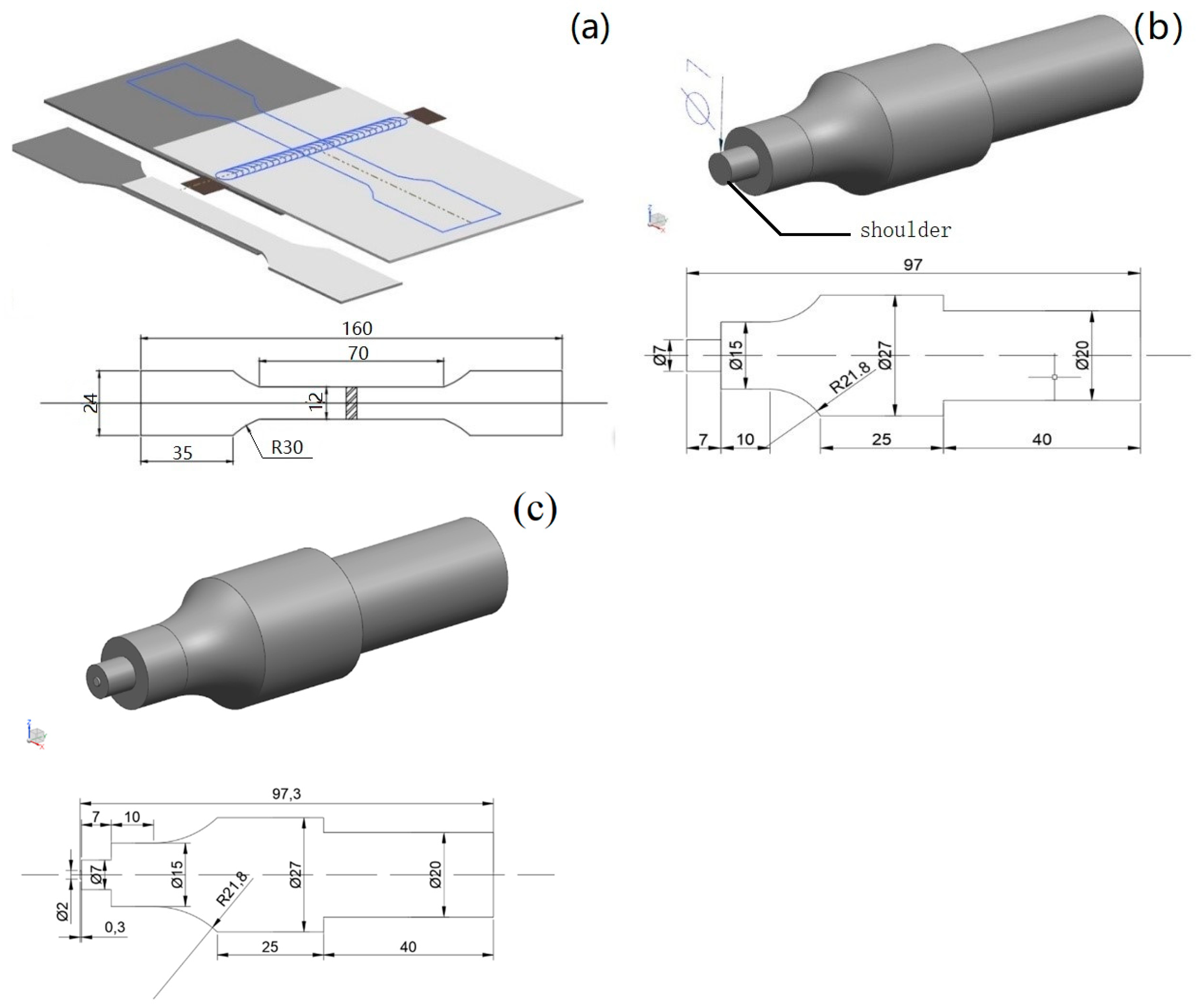
As shown in Figure 1a, the aluminium sheet and the galvanized steel sheet were placed on the welding platform, where the upper layer was the 6061-T6 aluminium sheet, the lower layer was the galvanized steel sheet, and the 99.99% zinc foil with different thicknesses was placed at the position directly below the weld seam. During the process of welding, the temperature at the boundary was collected by thermocouple, and the axial force of the welding tool was detected by sensor. The welding tools had no pin and a 0.3 mm pin, and a shoulder of 7 mm, as shown in Figure 1b,c. The friction stir welding machine (Self-developed products, Zhenjiang, China) had an inclination angle of 2.5°. The zinc foil was 12 mm × 100 mm, and the thicknesses were 50 μm, 100 μm and 200 μm. The welding speed was 50 mm/min, the weld length was 70 mm, and the rotation speed was 10,000 rpm. Before the test, the zinc foil was scrubbed with alcohol, and each group of tests was repeated three times. After the test, the metallographic samples were obtained at the welding seam. The specimens were polished with sandpaper and diamond suspension and then etched with Keller’s reagent. The microstructure of the weld cross section was observed with an optical microscope, and the interface composition and morphology were further analysed by SEM (Scanning Electron Microscope, Carl Zeiss AG, Zhenjiang, China) and EDS (Energy Dispersive Spectrometer, Carl Zeiss AG, Zhenjiang, China). The tensile specimen was cut perpendicular to the welding seam on the base metal, and the tensile shear test was carried out on a tensile machine. After the tensile-shear test, the fracture morphology was observed by SEM and photographed.

Figure 1.
(a) Welding schematic diagram, (b) welding tool without pin and (c) welding tool with 0.3 mm pin.
Galvanized steel sheets are mainly electro-galvanized steel sheets, alloy electro-galvanized sheets, hot-dip electro-galvanized sheets and alloy hot-dip electro galvanized sheets, of which hot-dip galvanized steel sheets are inexpensive and have the best corrosion resistance [20]. Therefore, a rectangular hot-dip galvanized steel sheet with the size of 150 mm × 80 mm × 1 mm and a 6061-T6 aluminium plate was selected for testing. The base materials were wiped with alcohol before the test to remove the greasy dirt on the surface of the test plate. The composition of the hot-dip galvanized steel sheet is shown in Table 1 (the thickness of the galvanized layer was approximately 10 μm). The microstructure is shown in Figure 2a.

Table 1.
Chemical composition of DX51D hot-dip galvanized steels.
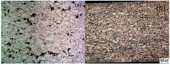
Figure 2.
(a) Microstructure of the hot-dip galvanized steel sheet, and (b) microstructure of the 6061-T6 alloy.
The 6061-T6 aluminium is an Al–Mg–Si-type aluminium. The measured tensile strength is 304 MPa, which is considered medium strength. The 6061-T6 aluminium has good plasticity and corrosion resistance [21], no stress corrosion cracking tendency, and excellent welding performance. Its composition is shown in Table 2. The microstructure is shown in Figure 2b.
Table 2.
Chemical composition of 6061-T6 aluminium.
To study the influence of the thickness of the zinc foil on the microstructure and mechanical properties of the joint, the thickness of the zinc foil was changed individually, and other welding parameters were controlled. The thickness of zinc foil was controlled, and the plunge depth of the shoulder of the welding tool was changed to study the effect of the shoulder pressure on the microstructure and mechanical properties. Early experiments found that when zinc foil was not added, it was difficult to weld the 6061-T6 aluminium and the galvanized steel sheet with the welding tool without the pin, and the mechanical properties of the joint were poor, while the 6061-T6 aluminium and galvanized steel plate could be welded with short-pin welding tools. Therefore, in this group of comparative tests, the short-pin welding tool was used to test the effect of the shape of the welding tool on the interface with different zinc foil thicknesses on the friction stir welding of aluminium–steel dissimilar alloys. In the comparative test of the welding tool with a pin, the welding tool with a 0.3 mm pin was selected to obtain sufficient axial force by increasing the plunge depth and avoiding abrasion caused by the pin touching the lower steel plate.
3. Experimental Results and Analysis
The test parameters and tensile test results are as Table 3.
Table 3.
Experimental parameters and tensile strength of No. 1–No. 19.
In the top view, Figure 3 shows the macroscopic shape of the weld in this test. Figure 3d shows the macroscopic shape of the weld for a tool with a 0.3 mm pin. The same welding parameters were used for each zinc foil thickness. A keyhole was left by the pin when leaving the work piece, which can be clearly observed at the end of the weld. Figure 3d shows the macroscopic morphology of the weld, which uses different thicknesses of zinc foil, from the top to the bottom: No zinc foil, 50 μm zinc foil, 100 μm zinc foil and 200 μm zinc foil. As the thickness of the zinc foil increased, the weld burr gradually increases. When the thickness of the zinc foil reached 200 μm, the welding process had poor stability, and the weld was not smooth and uniform. Figure 3a–c show the change in the surface of the weld with the increase in the plunge depth of the shoulder for the same thickness of the zinc foil, the thickness of zinc foil is 50 μm, 100 μm and 200 μm. Figure 3a–c show that when the zinc foil was thin and the plunge depth of the shoulder was small, the surface of the weld was smooth and continuous, and there was no burr. As the plunge depth of the shoulder increased, the thickness of the upper 6061-T6 aluminium gradually decreased. As shown in Figure 3a, the burr on the retreating side obviously increased. When the thickness of the zinc foil was 100 μm, the surface of the weld was uniform and smooth, but the retreating side had filamentous burr. The stability of the welding process deteriorated with increasing plunge depth.
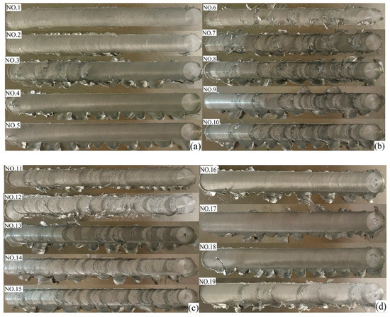
Figure 3.
Macroscopic morphology of welds: (a) No. 1–5 weld macroscopic morphology, (b) No. 6–10 weld macroscopic morphology, (c) No. 11–15 weld macroscopic morphology, and (d) No. 16–19 weld macroscopic morphology.
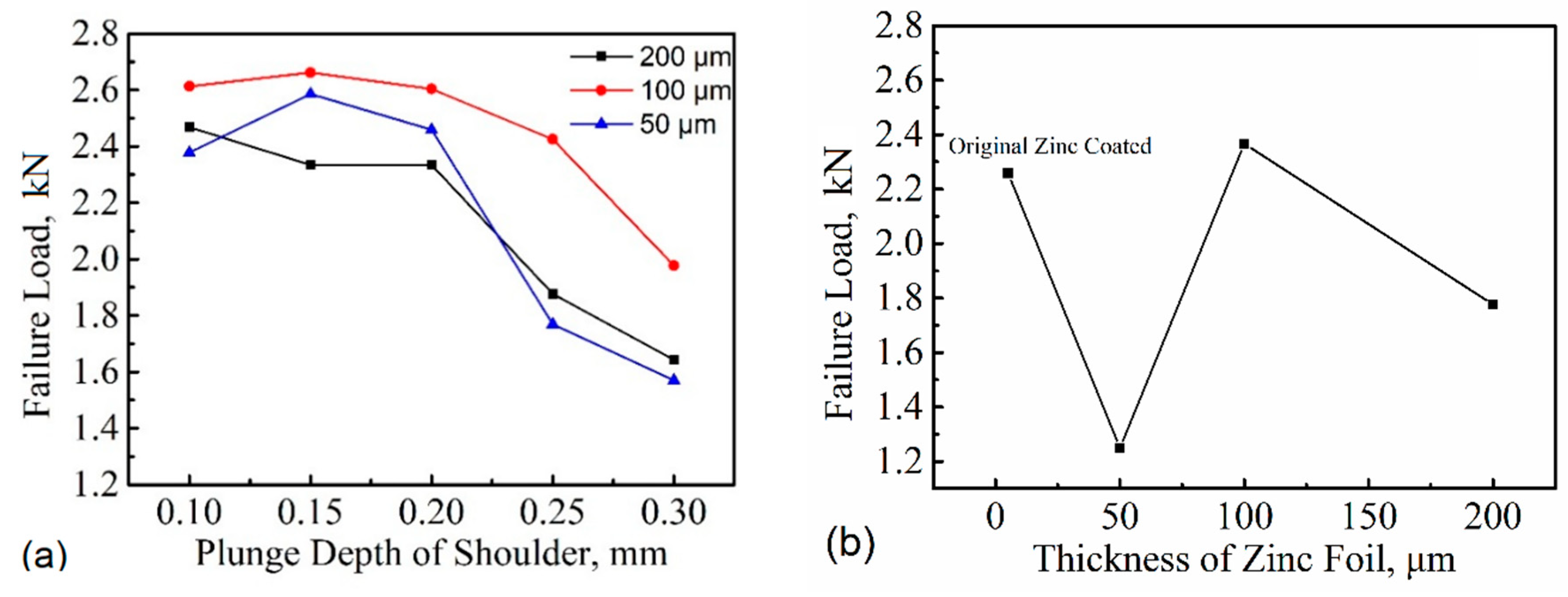
It can be seen from Figure 4a that when the tool was used without a pin, the mechanical properties of the 6061-T6 aluminium- and galvanized-steel sheet friction stir welded lap joints changed substantially with a change in the plunge depth of the shoulder. When the plunge depth was less than 0.2 mm, welding joints with high mechanical strength were obtained by adding three kinds of joints with different thicknesses of zinc foil. However, when the plunge depth was large, the mechanical properties of the joint gradually decreased due to the thinning of the 6061-T6 base material, and the lower the plunge depth, the lower the mechanical strength of the welded joint. When the tool with a 0.3 mm pin was used, the mechanical properties of the welded joint without the addition of zinc foil were better than those with the addition of 50 μm and 200 μm zinc foil but lower than those with the addition of 100 μm zinc foil. Overall, by adding zinc foil at the interface and using the tool without a pin, the mechanical properties of the welded joint obtained with appropriate welding parameters were better than those obtained with the tool with a pin. The joint obtained by welding the 6061-T6 aluminium and the galvanized steel with the tool without a pin and with an appropriate thickness of zinc foil was subjected to ductile fracture in the tensile test. It is easy to produce natural cracking with reduced storage temperature in the joint welded by using the tool with a pin [22,23].
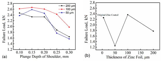
Figure 4.
(a) The change of tensile load with the plunge depth of the shoulder and (b) maximum tensile load varies with zinc foil thickness.
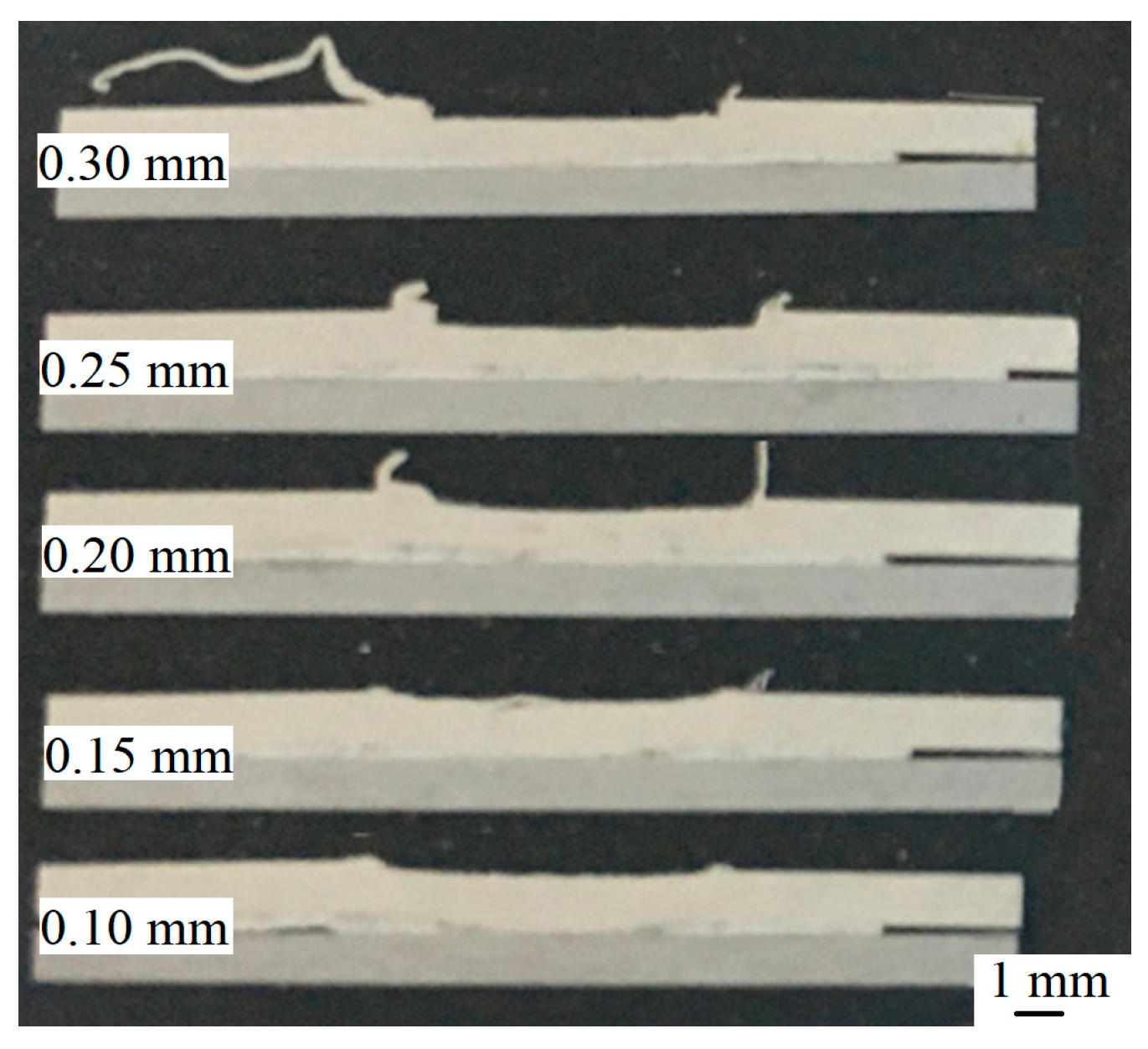
Figure 5 shows the metallographic sample obtained by electric spark cutting after the welding process. The metallographic sample was inlaid and polished to obtain smooth weld cross-section. Figure 5 shows the cross section of the welded joint obtained using the same zinc foil thickness and welding parameters but different shoulder plunge depths. The plunge depth from bottom to top was 0.10 mm, 0.15 mm, 0.20 mm, 0.25 mm, and 0.30 mm. It can be clearly observed from Figure 5 that as the plunge depth increased, the degree of thinning of the upper 6061-T6 base material layer also increased, and the burr also gradually increased.
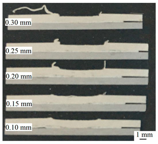
Figure 5.
Macroscopic morphology of weld cross section.
Figure 6 shows the temperature curve for the middle position on the forward side of the weld measured by the thermocouple in the welding process. Figure 6 shows that the welding began when the pin was inserted into the upper aluminium plate and the welding stage completed when the pin was withdrawn. The temperature increased with the approach of the heat source of the welding tool and then gradually decreased after the welding tool moved away from the test point. The Al–Zn eutectic, which has low melting point of approximately 381 °C, formed in the zinc-rich area. The overall temperature of the welding area was higher than that of zinc (420 °C) [12]. The peak temperature of the welding area just below the welding tool was 550 °C during the welding phase, which was higher than the peak temperature of friction stir welding that was used to weld aluminium–steel dissimilar joints. When no zinc foil was added and three different thicknesses of zinc foil were added for welding, the peak temperature was higher than 420 °C. When using the welding tool with a 0.3 mm pin, the peak temperature of the weld was higher than when the welding tool without a pin.
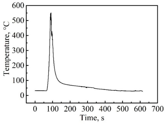
Figure 6.
Relationship between welding temperature and time.
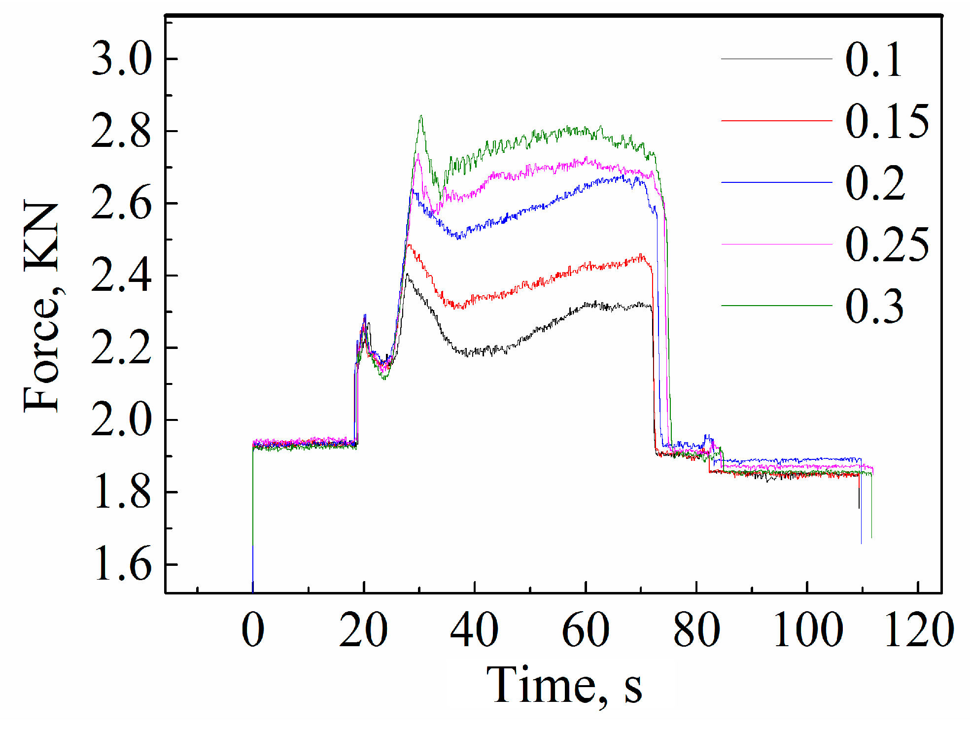
The pressure sensor was also used to collect the axial force during the welding process, as shown in Figure 7. With the same zinc foil thickness, the axial force increased with increasing plunge depth, and the number increased exponentially. In the work by Y. C. Chen et al. [12], the axial force during the welding process was 5.88 kN and the best welded joint was obtained with 0.1 mm and 0.2 mm plunge depth. The axial force in our case was only 2.7 kN, which is far lower than the axial force of the conventional friction stir welding process and greatly reduced the welding deformation; this approach is especially suitable for thin plate welding.
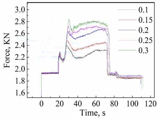
Figure 7.
Relationship between axial force and the plunge depth of the shoulder.
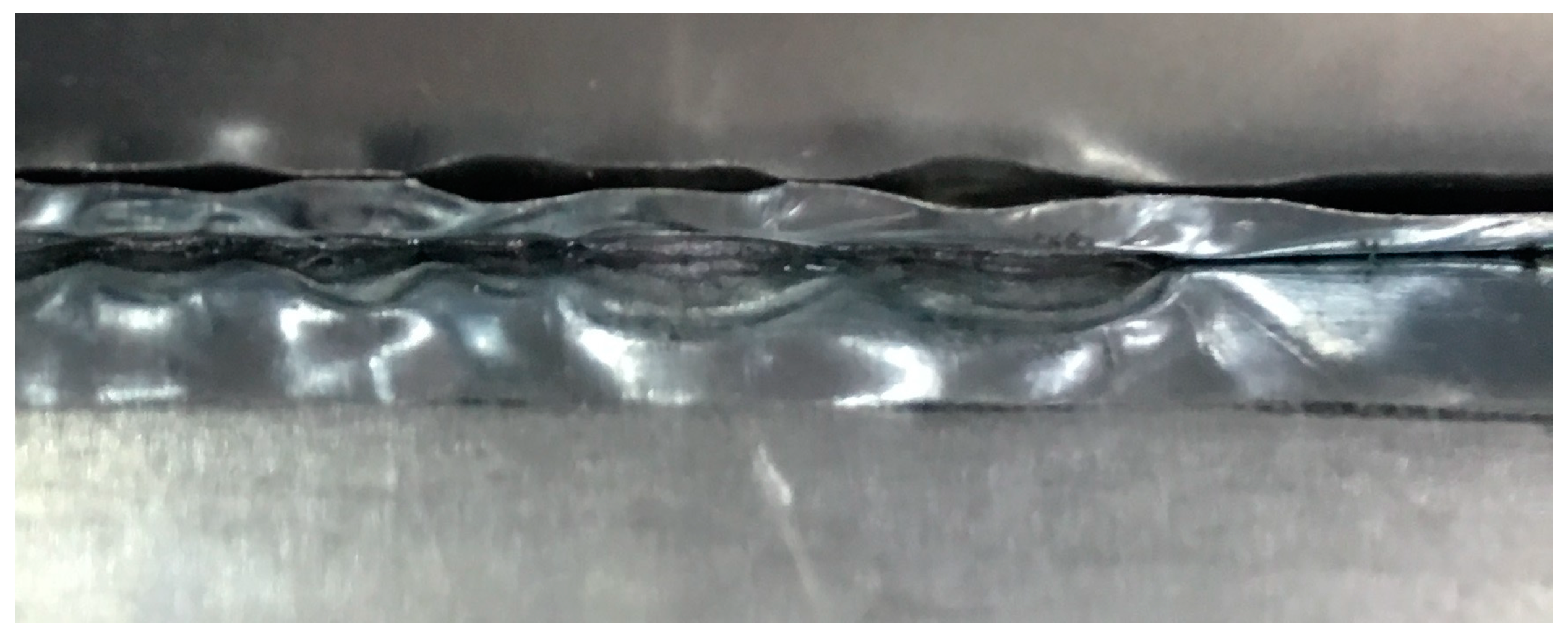
The interface temperature of the Al/Zn/steel exceeded the melting point of Zn, which resulted in the zinc layer at the interface melting completely during welding. During the welding process, the interface behind the tool rapidly cooled and solidified, but the zinc at the interface directly below the tool melted, was easily extruded from the interface and did not provide sufficient support force. As shown in Figure 8, periodic accumulation of zinc and voids occurred at the interlayer interface. This is also the reason that the interfacial structure of the aluminium plate was not uniform and continuous while the mixing head moved. With the increase of the plunge depth of the shoulder, the axial force of the aluminium plate increased gradually. The support force at the interface between the front and rear of the tool was different, which led to the step-by-step movement of the stirrer head during welding, resulting in an unstable welding process. Therefore, when the thickness of the zinc foil was the same, the forming quality of the weld surface decreased with an increase in the plunge depths of the shoulder, and formation of an uneven fish-scale on the weld surface clearly increased.
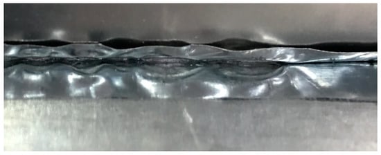
Figure 8.
Macroscopic longitudinal section of weld.
With the increase in the thickness of the zinc foil, the melted zinc at the weld overlap interface became thicker, which led the liquid at the interlayer interface to become thicker upon the initiation of the welding process. The stability of it was worse than that for the thinner zinc foil. The step type advance degree was more serious, the uneven fish-scale pattern that appeared on the weld surface increased.
The IMC types, distribution and thickness in the interlayer had decisive influence on the mechanical properties of the 6061-T6 aluminium and galvanized steel sheet friction stir welded joints. The SEM observation of the welding interface showed that the composition of the interlayer was quite distinct when the thickness of the zinc foil was different. During the welding process, the heat generated by the friction between the shoulder and the upper surface was transferred to the interface through the upper aluminium plate. With the plunge of the tool, the oxide film on the lower surface of 6061-T6 aluminium sheet and the surface of galvanized steel sheet was extruded and crushed due to the temperature and pressure. At the same time, the zinc on the interface and the surface of the galvanized steel sheet was melted. Moreover, Al diffused to the interface and bonded with the Zn to form an Al–Zn eutectic with low melting point.
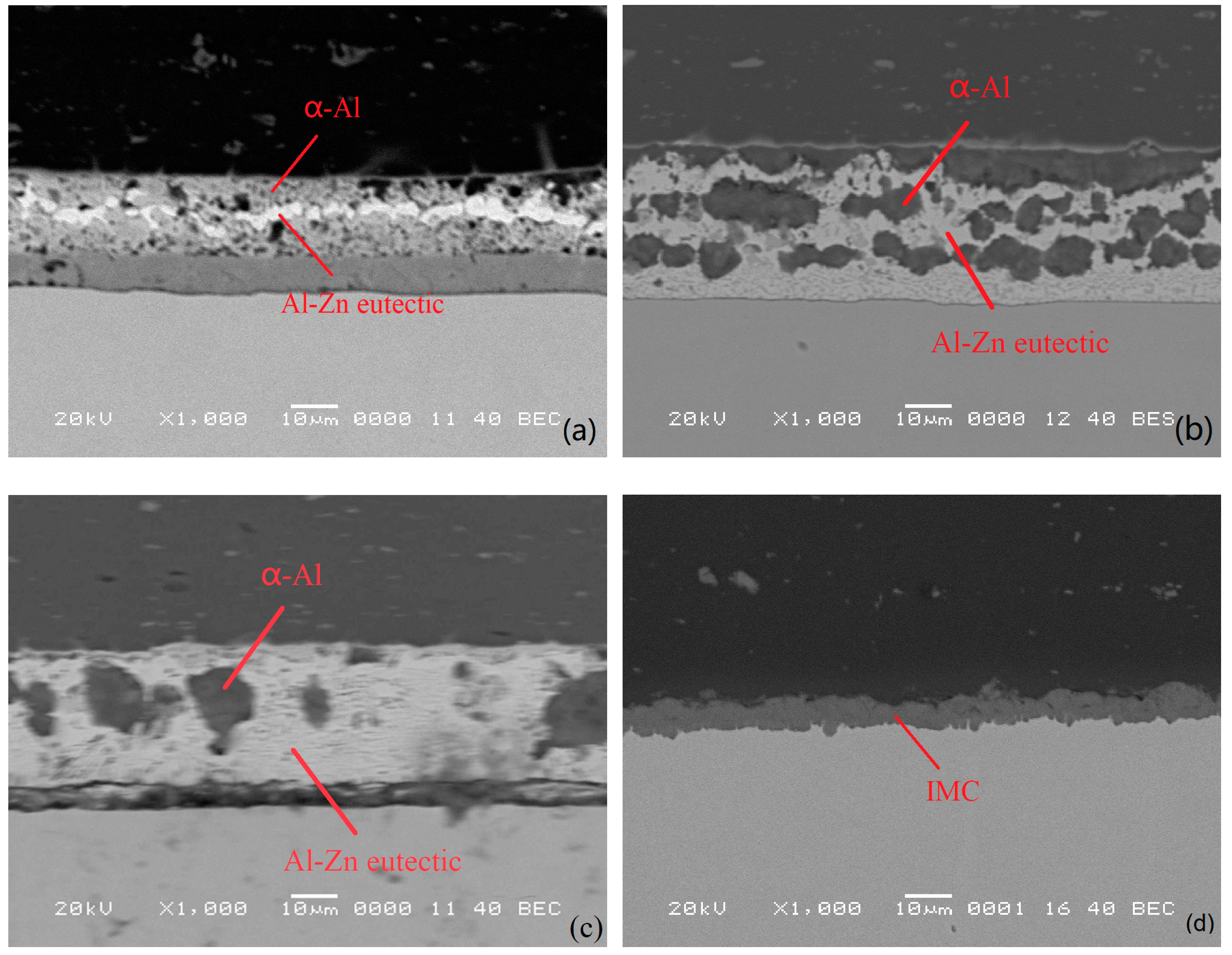
The tool without pin was used for the FSW of the 6061-T6 and zinc-coated steel with zinc foil at the interface. However, the thickness of zinc foil greatly influenced the phase of the joint interface. In this situation, when without zinc foil, the Al–Zn eutectic generated below the shoulder was pushed into the edge of the tool shoulder by the tool gradually penetrating into the upper sheet. However, because of the lack of localized pressure, the Al–Fe IMC was not generated at the interface. Thus, when the tool was without a pin and without zinc foil, the weldability was not good. The experimental results show that the addition of zinc foil can improve the strength of the joint. When the 50 μm zinc foil was used, as shown in Figure 9a, Al and zinc were combined to form Al–Zn eutectic at the interface. The compositions are shown in Table 4 and Table 5. When the penetration depth was excessively large, because the affinity between Al and Fe is much stronger than that of Zn and Fe [24], the original zinc coating contained a small amount of Al, so the Al–Zn eutectic was based on Al generated as the layer approached the steel surface. At the same time, the segregation of excrescent zinc occurred at the middle of the interface. The intergranular fracture took place at the segregation layer, and the micro-morphology is shown in Figure 10a. When the 100 μm zinc foil was used, Al and zinc were combined into the Al–Zn eutectic at the interface. However, Al could not diffuse into the entirety of the zinc foil. Therefore, the upper Al–Zn eutectic consisted of Al–Zn eutectic rich in Al, and the lower Al–Zn eutectic consisted of Al–Zn eutectic rich in Zn, as shown in Figure 9b. The two kinds of phases were mixed together, and the joint performed well during the tensile test. The fracture took place on the advancing side of the 6061-T6 aluminium. After the tensile test, the joint became detached. Figure 10b shows that the dispersed distribution of the Al–Zn eutectic rich in Al is among the Al–Zn eutectic rich in Zn, which prevented intergranular fracture. When 200 μm zinc foil was used, as shown in Figure 9c, the interface behaviour was similar to that with the 100 μm zinc foil. For thick Zn foil, the whole interface consisted of Al–Zn eutectic rich in zinc, and only the top of the interface contained a small amount of Al–Zn eutectic rich in Al. The fracture took place at the advancing side of the 6061-T6 aluminium. The micro-morphology of the fracture is shown in Figure 10c.
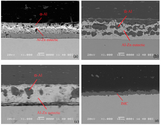
Figure 9.
(a) No. 4 interface microstructure, (b) No. 7 interface microstructure, (c) No. 11 interface microstructure, and (d) No. 16 interface microstructure.
Table 4.
Composition of Al–Zn eutectic.
Table 5.
Composition of α-Al.

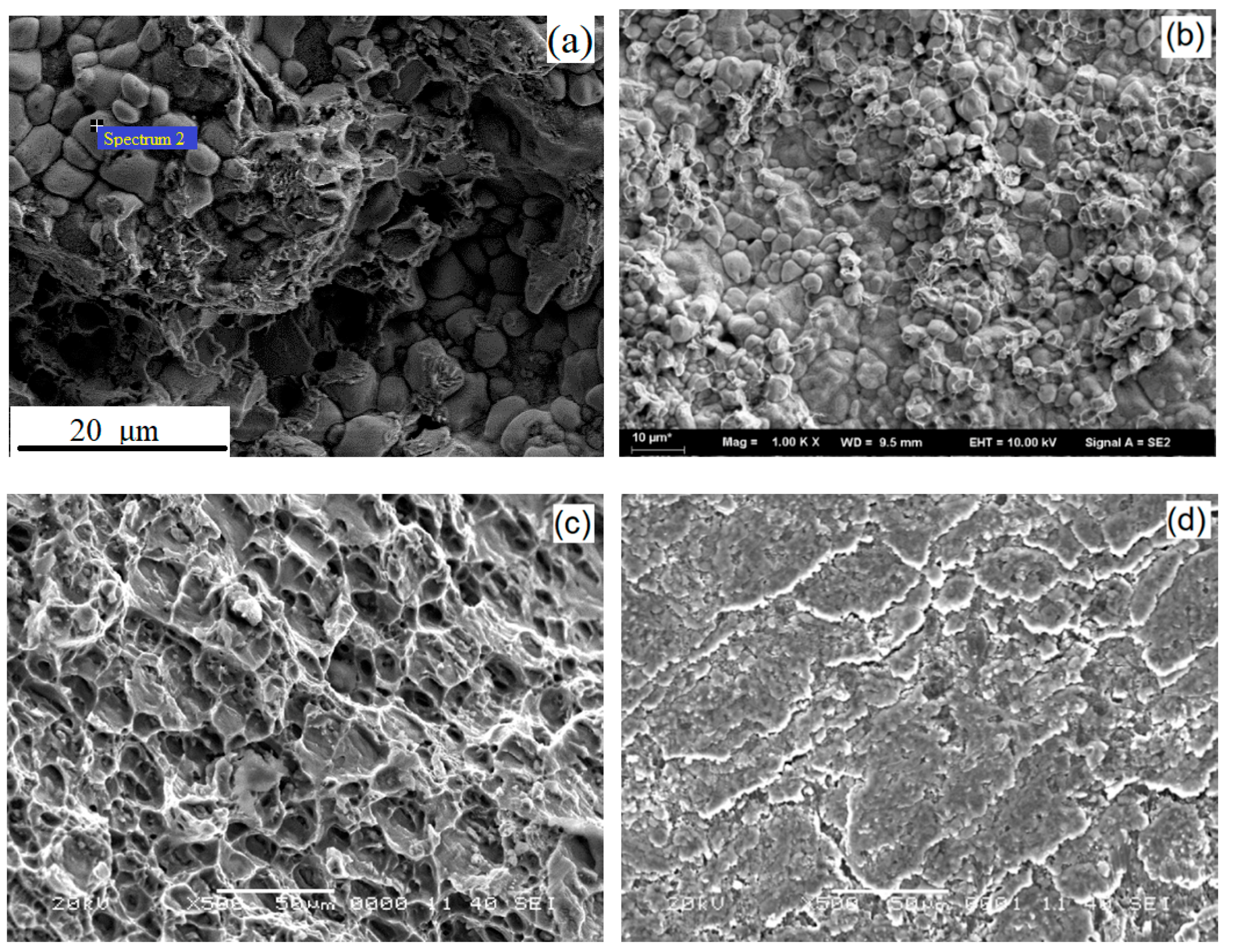
Figure 10.
(a) No. 4 fracture surface morphology of aluminium side, (b) No. 7 microstructure of the steel interface surface after separating the parent metal on the upper and lower sides, (c) No. 11 microstructure of aluminium side, and (d) No. 16 fracture surface morphology of steel side.
The tool with a 0.3 mm pin was used in the FSW of the 6061-T6 aluminium and zinc-coated steel without zinc foil at the interface. When the tool gradually penetrated the upper sheet, the Al–Zn eutectic generated below the pin was pushed to the edge of the tool shoulder due to the localized pressure. The Al alloy sheet contacted the steel sheet immediately and Al and Fe elements diffused toward the interface due to the pressure and heat; then the rigid Al–Fe intermetallic compounds formed at the interface. The compositions of the IMC are shown in Table 6. As shown in Figure 10d, the joint fractured in the HAZ (Heat Affected Zone) on the advancing side of the 6061-T6 aluminium during the tensile test. We detached the joint from the interface and found layered IMC in the scanning electron microscope, as shown in Figure 9d. However, by increasing the thickness of the zinc foil, the remaining zinc on the steel sheet thickened, and the diffusion of Al and Fe became more difficult. A thinner IMC was generated at the interface with thick foil than that generated without zinc foil. The fracture took place at the interface of the joint during the tensile test, and the failure load was lower than that without zinc foil. When the zinc foil was thick enough, the Al could not get through the zinc foil and reach the surface of the zinc-coated steel, no IMC was generated, and the major phase was Al–Zn eutectic. In addition, the Zn–Fe IMC Fe5Zn21 generated during the zinc coating process of the steel remained on the surface of the steel sheet, and the fracture took place on the advancing side of the 6061-T6 aluminium.
Table 6.
Composition of intermetallic compounds (IMC).
4. Conclusions
A friction stir welding process test of a 6061-T6 aluminium sheet and a galvanized steel sheet was carried out by adding zinc foil of different thicknesses to the lap interface. The effects of the thickness of zinc foil, the plunge depth of the shoulder and the shape of the pin head on the microstructure and mechanical properties of aluminium–steel lap joints were studied. The following conclusions were drawn.
(1) Under small axial force, high rotation speed can obtain excellent performance lap joints. Compared with the welded joint without zinc foil [12], the addition of zinc foil effectively prevented direct contact between the aluminium and steel, and reduced the generation of brittle intermetallic compounds, such as Fe4Al13. Thus, stable welded joints were obtained.
(2) The addition of zinc foil resulted in the formation of an Al–Zn eutectic with low melting point; this material was squeezed by the tool with a pin at the interface, so the tool without a pin was more suitable for this process. However, for the test without the addition of zinc foil, the tool with a short pin was more conducive to the formation of a uniform and thick IMC to achieve the connection.
(3) The Al–Zn eutectic with low melting point played an important role in the connection. Moreover, when the thickness of the zinc foil was moderate, the interfacial microstructure was more uniform and compact and led to welded joints with excellent mechanical properties. At the same time, the plunge depth of the shoulder should be controlled so as to not be too large because this affected the appearance of moulding. Otherwise, the upper aluminium base material was severely sheared. When the thickness of zinc foil was 100 μm and the plunge depth was 0.15 mm, welded joints with good mechanical properties were obtained. The maximum axial force was only 2.7 kN. The maximum tensile load reached 2.66 kN, 36.45% of the tensile strength of aluminium.
(4) The results of this study are suitable for the lap joints of aluminium and steel structural parts with small structure or small bearing capacity. If high connection strength is required, multi-pass welding can be used. However, the longitudinal continuity of the weld needs to be improved and further research is needed.
Author Contributions
Methodology, S.C.; experiment, J.Z.; writing—review and editing, L.M., J.Z., D.W., H.Z. and X.W.
Funding
This research was funded by Qing Lan Project, National Post Doctoral Fund and the National Natural Science Foundation of China (51675248) and the Natural Science Fund of the Jiangsu Higher Education Institutions of China (17KJA460006) and Natural Science Foundation of Jiangsu (BK20171308).
Conflicts of Interest
The authors declare no conflict of interest. The funders had no role in the design of the study; in the collection, analyses, or interpretation of data; in the writing of the manuscript, or in the decision to publish the results.
References
- Wang, F.; Xiong, B.Q.; Zhang, Y.G.; Liu, H.W.; He, X.Q. Microstructural development of spray-deposited Al-Zn-Mg-Cu alloy during subsequent processing. J. Alloys Compd. 2009, 477, 616–621. [Google Scholar] [CrossRef]
- Balasubramanian, V.; Ravisankar, V.; Reddy, G.M. Effect of pulsed current welding on fatigue behaviour of high strength aluminium alloy joints. Mater. Des. 2008, 29, 492–500. [Google Scholar] [CrossRef]
- Knipst, R.E.; Pekkari, B. Friction stir welding process goes commercial. Weld. J. 1997, 76, 55–59. [Google Scholar]
- Bagheri, A.; Azdast, T.; Doniavi, A. An experimental study on mechanical properties of friction stir welded ABS sheets. Mater. Des. 2013, 43, 402–409. [Google Scholar] [CrossRef]
- Cao, X.; Jahazi, M. Effect of tool rotational speed and probe length on lap joint quality of a friction stir welded magnesium alloy. Mater. Des. 2011, 32, 1–11. [Google Scholar] [CrossRef]
- Choi, D.H.; Ahn, B.W.; Lee, C.Y.; Yeon, Y.M.; Song, K.; Jung, S.B. Formation of in-termetallic compounds in Al and Mg alloy interface during friction stir spot welding. Intermetallics 2011, 19, 125–130. [Google Scholar] [CrossRef]
- Mishra, R.S.; Ma, Z.Y. Friction stir welding and processing. Mater. Sci. Eng. 2005, 50, 1–78. [Google Scholar] [CrossRef]
- Elrefaey, A.; Gouda, M.; Takahashi, M.; Ikeuchi, K. Characterization of aluminium/steel lap joint by friction stir welding. J. Mater. Eng. Perform. 2005, 14, 10–17. [Google Scholar] [CrossRef]
- Das, H.; Pal, T.K. High Cycle Fatigue Behaviour of Friction Stir Lap Welded 6061 Aluminium to Coated Steel Sheet Joint. Trans. Indian Inst. Met. 2015, 68, 959–968. [Google Scholar] [CrossRef]
- Chen, Y.C.; Komazaki, T.; Kim, Y.G.; Tsumura, T.; Nakata, K. Interface microstructure study of friction stir lap joint of AC4C cast aluminium and zinc-coated steel. Mater. Chem. Phys. 2008, 111, 375–380. [Google Scholar] [CrossRef]
- Zhang, G.; Su, W.; Zhang, J.; Wei, Z. Friction Stir Brazing: A Novel Process for Fabricating Al/Steel Layered Composite and for Dissimilar Joining of Al to Steel. Metall. Mater. Trans. A 2011, 42, 2850–2861. [Google Scholar] [CrossRef]
- Chen, Y.C.; Nakata, K. Effect of the surface state of steel on the microstructure and mechanical properties of dissimilar metal lap joints of aluminium and steel by friction stir welding. Metall. Mater. Trans. A 2008, 39, 1985–1992. [Google Scholar] [CrossRef]
- Chen, Y.C.; Komazaki, T.; Tsumura, T.; Nakata, K. Role of zinc coat in friction stir lap welding Al and zinc coated steel. Mater. Sci. Technol. 2008, 24, 33–39. [Google Scholar] [CrossRef]
- Kimapong, K.; Watanabe, T. Lap Joint of A5083 Aluminium and SS400 Steel by Friction Stir Welding. Mater. Trans. 2005, 46, 835–841. [Google Scholar] [CrossRef]
- Kimapong, K.; Watanabe, T. Effect of Welding Process Parameters on Mechanical Property of FSW Lap Joint between Aluminium and Steel. Mater. Trans. 2005, 46, 2211–2217. [Google Scholar] [CrossRef]
- Kumar, K.; Kailas, S.V. On the role of axial load and the effect of interface position on the tensile strength of a friction stir welded aluminium. Mater. Des. 2007, 29, 791–797. [Google Scholar] [CrossRef]
- Chen, S.; Zhou, Y.; Xue, J.; Ni, R.; Guo, Y.; Dong, J. High Rotation Speed Friction Stir Welding for 2014 Aluminium Thin Sheets. J. Mater. Eng. Perform. 2017, 26, 1–9. [Google Scholar] [CrossRef]
- Zheng, Q.; Feng, X.; Shen, Y.; Huang, G.; Zhao, P. Dissimilar friction stir welding of 6061 Al to 316 stainless steel using Zn as a filler metal. J. Alloys Compd. 2016, 686, 693–701. [Google Scholar] [CrossRef]
- Su, X.P.; Tang, N.Y.; Toguri, J.M. Thermodynamic evaluation of the Fe-Zn system. J. Alloys Compd. 2001, 325, 129–136. [Google Scholar] [CrossRef]
- Marder, A.R. The meltallurgy of zinc-coated steel. Prog. Mater Sci. 2000, 45, 191–271. [Google Scholar] [CrossRef]
- Zaid, B.; Saidi, D.; Benzaid, A.; Hadji, S. Effects of pH and chloride concentration on pitting corrosion of AA6061 aluminum alloy. Corros. Sci. 2008, 50, 1841–1847. [Google Scholar] [CrossRef]
- Miyazaki, S.; Kawachi, A.; Kumai, S.; Sato, A. Plastic deformation of hardly deformable Al13Fe4, particles embedded in an Al–Al13Fe4, dual phase alloy. Mater. Sci. Eng. A 2005, 400–401, 294–299. [Google Scholar] [CrossRef]
- Yoneyama, N.; Mizoguchi, K.; Kumai, S.; Sato, A.; Kiritani, M. Plastic deformation of Al13Fe4, particles in Al–Al13Fe4, by high-speed compression. Mater. Sci. Eng. A 2003, 350, 117–124. [Google Scholar] [CrossRef]
- Mandal, G.K.; Balasubramaniam, R.; Mehrotra, S.P. Theoretical investigation of the interfacial reactions during hot-dip galvanizing of steel. Metall. Mater. Trans. A 2009, 40, 637–645. [Google Scholar] [CrossRef]


© 2019 by the authors. Licensee MDPI, Basel, Switzerland. This article is an open access article distributed under the terms and conditions of the Creative Commons Attribution (CC BY) license (http://creativecommons.org/licenses/by/4.0/).