Article

Development of a Novel Resistance Heating System for Microforming Using Surface-Modified Dies and Evaluation of Its Heating Property

Tokyo Metropolitan University, Tokyo 191-0065, Japan
*
Author to whom correspondence should be addressed.
Metals 2019, 9(4), 440; https://doi.org/10.3390/met9040440
Submission received: 20 March 2019 / Revised: 7 April 2019 / Accepted: 11 April 2019 / Published: 15 April 2019
(This article belongs to the Special Issue Metal Micro-forming)

Abstract

:
For this study, a novel resistance heating system for microforming was developed using surfaces of forming dies as heating resources. The electrical resistance of the die surfaces was designed and the hard-coating material AlCrSiN was selected to coat the die surfaces for heating. To clarify the effects of the thickness and modified surfaces on heating efficiency, the temperature and stress reduction were evaluated in a micro-compression test using dies coated with 0.5 and 1 μm AlCrSiN films. Furthermore, the formability was also demonstrated using 1 μm thick AlCrSiN-coated tools in a microforging test. By applying surface-modified dies to the forming processes, we found that not only was the heating efficiency improved, but also the dependence of heating on the product’s shape and the material’s electrical properties was reduced.

1. Introduction

In the fields of medical, precision, and electronic information equipment, the demand for fine metal components is increasing, and microforming processing technology has attracted much attention. However, there are several issues due to the scaling-down of material, such as reduction in ductility and uneven deformation of materials; therefore, the development of materials and processes suitable for microforming is required [1,2,3]. Heat-assisted microforming is a promising approach since the effects of heating, such as reduction in flow stress and uneven deformation, are expected to contribute to improved formability in microforming processes [4,5]. Several localized heating systems including laser heating, ultrasonic heating, and electrical heating have been investigated. It has been established that heat assistance could reduce the flow stress of a material. In laser heating, efficient heating can be realized by using high-power or pulsed lasers, which have been applied in flexible sheet bending [6], dieless micro-tube forming [7], and stamping processes with transparent dies [8]. However, the use of transparent dies could be a limitation in industrial applications. In electrical heating, the heating system can be embedded in dies for efficient heating [9]. Moreover, the reduction in flow stress in the deep drawing of a metal foil material, the reduction in the springback in foil bending [10,11,12], and further surface smoothing [9] in microforging have been confirmed. However, some issues in the electrical heating system should be overcome as shown below. Since the current flow in a workpiece shows a dependence on the shape of the products, it is necessary to optimize the electrode allocation for various product shapes to prevent a non-uniform temperature distribution due to the current density gradient in the workpiece [13]. Since the heating depends on the electrical resistance of the workpiece, a high electric energy is required for materials with lower electrical resistivity. Furthermore, since the resistance of the workpiece varies owing to deformation, the temperature will also change accordingly with the progress of the deformation during a process.
In this study, we aimed to develop a new electric heating system that does not depend on the material properties and shape to overcome the issues encountered in previous heating systems. We designed and fabricated this new electrical heating system for generating heat on the die surface by forming a modified layer with high electrical resistivity on the surface of the dies. The heating system was subjected to a compression test to evaluate the effects of materials with various electrical resistivities. The heating system was also applied to microforging to evaluate its effects on formability and accuracy in microforging.

2. Design and Surface Treatment of Electrode Dies

Figure 1 shows a schematic diagram of the proposed method in this study. Surface treatment was applied to modify the die surfaces to design their electrical resistance as a heat source for heating. It is a novel idea that the surfaces of dies can function as a heat source by modifying not only their mechanical properties, namely, heat resistance, and seizure resistance, but also their electrical properties. As a result, a workpiece can be heated through thermal conduction from itself of a die in contact with the workpiece. Finite element (FE) analysis was carried out to design the electrical resistivity of the die surface for an electric heating system. Then, the surface coating material was selected based on simulation results and deposited on the die surface by a commercial physical vapor deposition (PVD) process. Finally, the heating characteristics were evaluated by microforming tests using the coated dies.

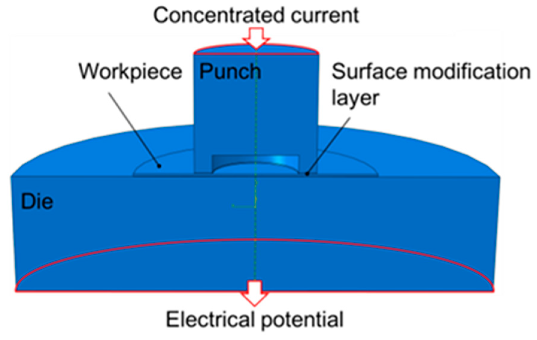
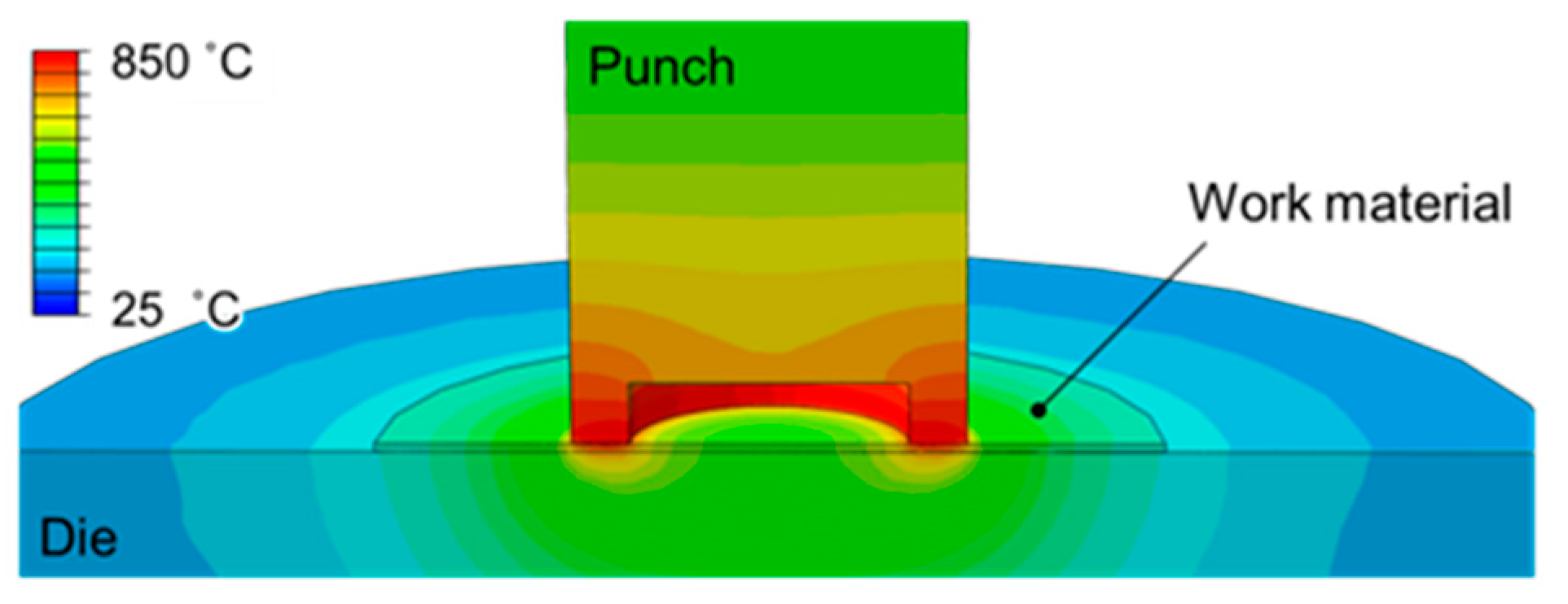
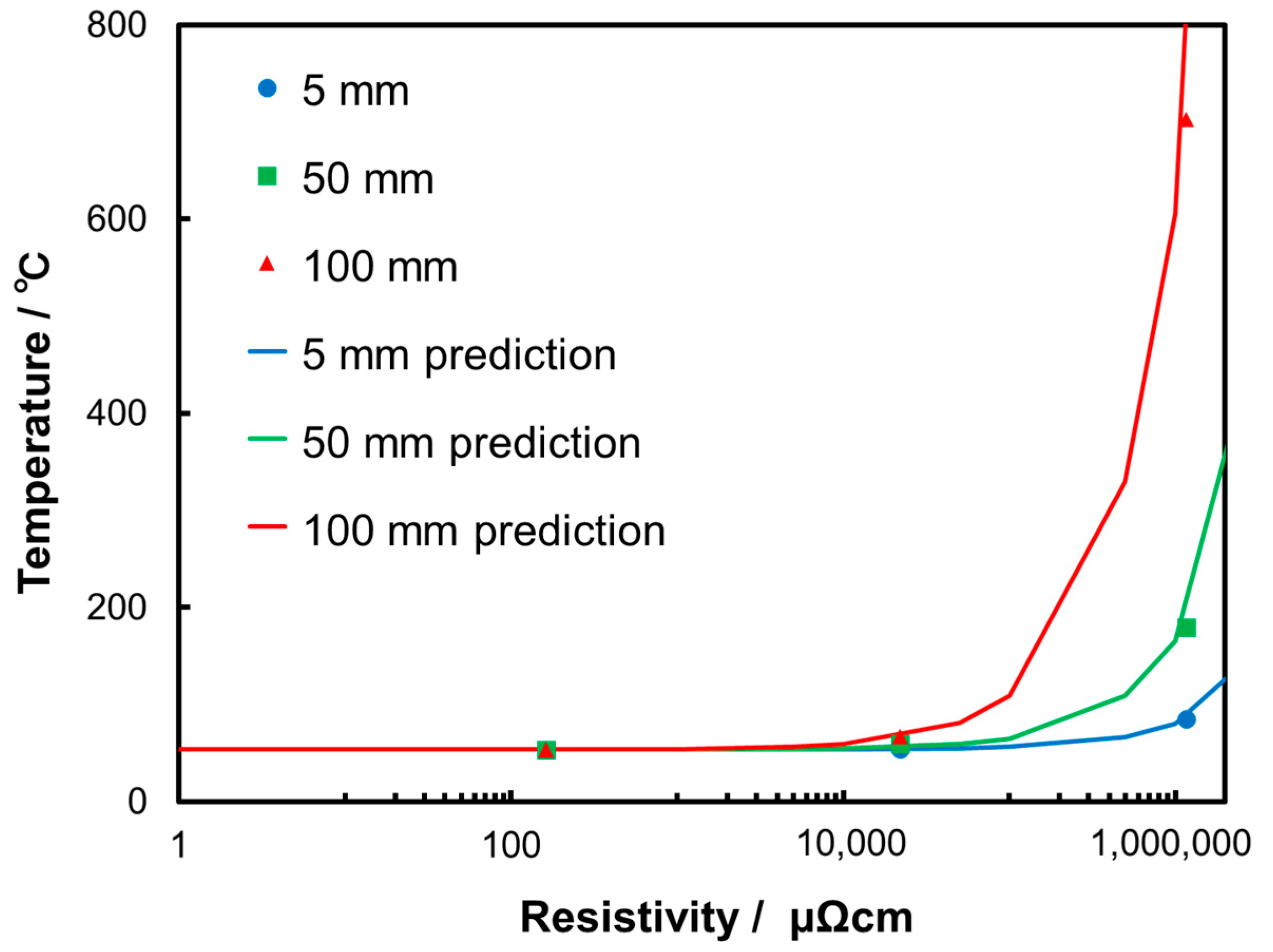
2.1. Simulation for Design of Die Surface

The effects of the thickness and electrical resistivity of the surface layer of dies on the heating properties were evaluated by FE analysis in order to determinate the conditions of the surface layer required for heating. A coupled thermal-electric analysis was performed using the commercial code ABAQUS 6.17 (Dassault Systemes, Vélizy-Villacoublay, France, 2017) and the conditions of FE analysis are shown in Table 1. Figure 2 shows the boundary conditions for the analysis. The materials used for surface coating are shown in Table 2. A step input of a direct current of 40 A was applied from the top of the punch through the lower die which had a potential of 0 V. The initial and ambient temperatures of the surfaces of the punch, workpiece, and die were all 25 °C.
Figure 3 shows the FE analysis results of the temperature distribution 60 s after heating. It was confirmed that local heating is achieved by thermal conduction from the punch surface to the workpiece. Electric heating was found to be much less dependent on the resistance property of the workpiece in the case of surface modification of the die by coating a material with a much higher electrical resistivity on the die surface. A higher temperature was achieved by coating a material with a greater thickness and higher electrical resistivity at the same input energy. The maximum temperature in the workpiece was 780 °C in the case of the 100 μm thick CrN0.6 layer. Based on the FE analysis results, the relationship between the achievable temperature and the resistivity of the coated material was estimated. Figure 4 shows the prediction results. The prediction curve fitted the simulation results well, indicating that an electrical resistivity of 2.8 × 10⁶ μΩcm is necessary for the coating film with a thickness of 50 μm and that of 6.7 × 10⁷ μΩcm is necessary for thickness of 5 μm in the case of a target temperature of 800 °C. In our previous study, a high-density plasma nitriding was performed to modify a surface of tool steel in order to increase the electrical resistivity of the die surface [14]. The surface layer with a thickness of 50 μm was modified, but still not enough to achieve the desired temperature. It is necessary to choose materials with higher resistivities for the surface modification.

2.2. Selection of Material and Die Coating

Three kinds of commercial ceramic coating materials used for cutting tools were investigated from the viewpoint of heat resistance and seizure resistance at more than 800 °C. The ceramics coated to a thickness of 1 μm on stainless steel (JIS: SUS420J2) by PVD process and their electrical resistance were measured using a digital multimeter (VOAC7522H, IWATSU ELECTRIC CO.,LTD., Tokyo Japan). The results are shown in Table 3. All three coated materials show higher electrical resistivities than the uncoated material. Since the AlCrSiN coating had the highest heat resistance and a maximum electrical resistivity of 2 × 10¹² μΩcm, it was coated on the die for the forming test.

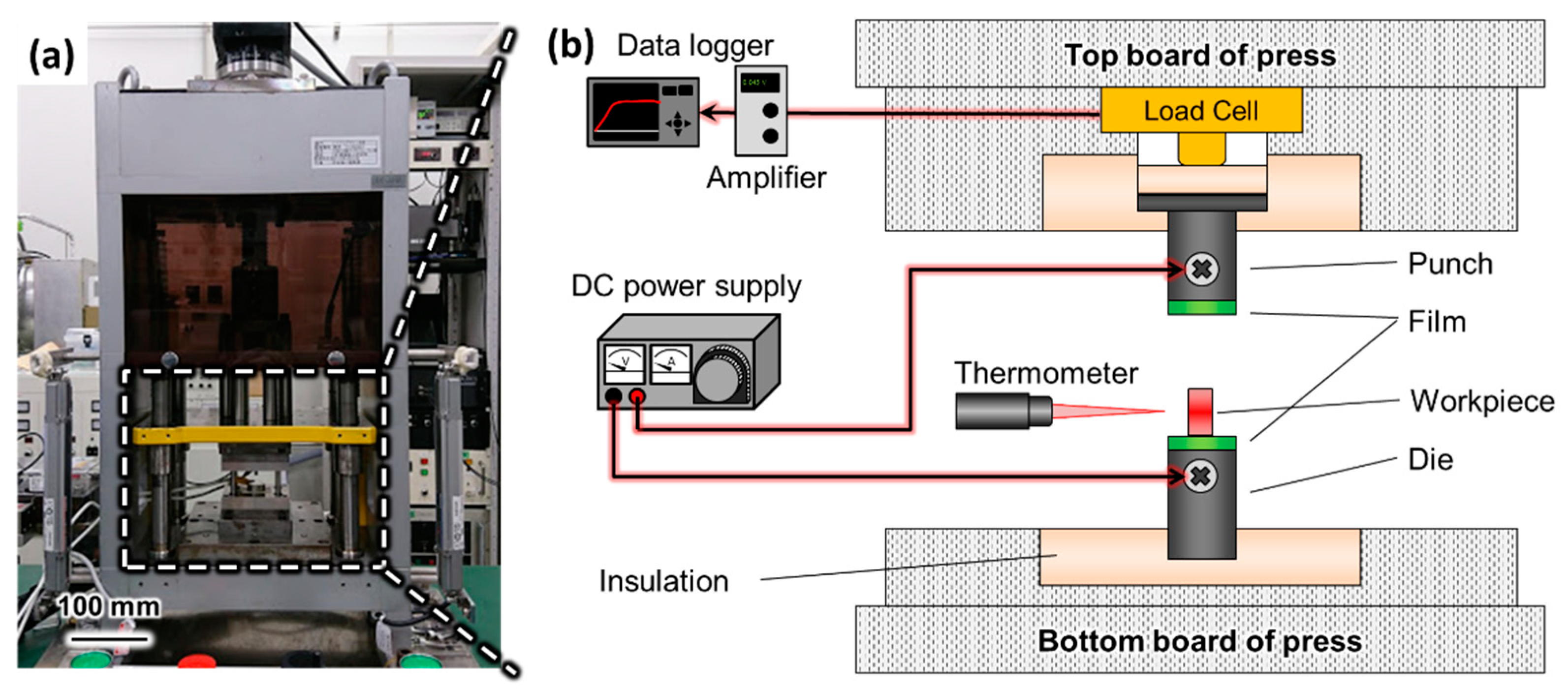
3. Evaluation of Heating System

The configuration of the microforming system with surface-modified dies is shown in Figure 5. The surface-modified dies are attached to a tabletop servo press machine (HJ50, Micro Fabrication Lab, Tokyo, Japan) and the dies are insulated in the press machine with a ceramic plate. The dies and workpiece are heated by connecting a power supplier to the dies during the forming process and the temperature is measured during heating using a radiation thermometer (FTK-R160R-5R21, TMC9-MPN). A compression test using the dies coated with AlCrSiN with thicknesses of 0.5 and 1 μm was carried out in comparison with uncoated dies. To evaluate the heating dependence on the material properties, pure titanium, pure copper, and stainless steel (JIS: SUS304) with the same cylindrical shape were used as test specimens. Changes in the temperature during the compression test were measured to evaluate the temperature dependence on the deformation. After the initial loading at 50 N, a DC current in the range of 10 to 60 A was applied, and the temperature of the specimen surface in the steady state was recorded. In the compression test, the strain rate was 0.005 s−1, and the stroke for the compression was 0.8 mm. In order to suppress the effect of friction during processing, graphite powder was sprayed on the upper and lower surfaces of the specimen.
Stress–strain curves for pure titanium with a uniform initial temperature of 600 °C are shown in Figure 6. The flow stress increases gradually as the deformation progresses in the uncoated dies, whereas it is relatively constant in the AlCrSiN-coated dies. Since the flow stress for Ti decreases significantly with the increase of temperature [15], this result indicates that the changes in temperature during the process may affect the flow stress of the workpiece. The changes in temperature are shown in Figure 7. Under all conditions, the temperature tends to decrease with increasing strain, but the rate of temperature decrease was suppressed with the increase in the thickness of the die coating. The tendency of the temperature decrease is caused by the reduction in the joule heat of the material caused by the increase in the compressive strain in the axial direction of the material; as a result, the current density decreases owing to the decrease in the length and increase in the diameter of the specimen. In the coated dies, the temperature drop due to material deformation was suppressed by heat conduction from the die surface and this suppression effect was greater in the coating with higher resistivity. As a result, although the initial temperatures were the same under the three conditions, the flow stress markedly increased with the progression of the process in the uncoated dies compared with the coated dies.
Figure 8 shows heating temperatures at different current densities for the three materials. Higher heating temperatures were achieved for the coated dies than for the uncoated dies, and higher temperatures were confirmed for the coated dies with a thicker coating. In the case of processing the pure titanium with the coating thickness of 1 μm, a temperature of 780 °C was achieved at a current density of 51 A/mm2, which is 350 °C higher than the average temperature achieved at the same current density for the uncoated dies. In order to quantitatively evaluate the increase in temperature for individual materials, the rate of temperature increase at a current density of 38 A/mm2 was evaluated, and the results are shown in Figure 9. The rate of temperature increase was defined as follows:
Tincrease rate = (Tcoated − Tuncoated)/Tuncoated × 100%.
The electrical resistivities of the three materials used are 1.7 μΩcm for Cu, 54 μΩcm for Ti, and 72 μΩcm for SUS304. As shown in Figure 9, a higher rate of temperature increase was obtained for all materials with thicker coated dies. The maximum rate of temperature increase was confirmed for pure copper, which has the lowest electrical resistivity and is difficult to heat using the conventional heating system. This means that the new heating system can reduce the temperature dependence of the electrical resistivity of the workpiece.
In addition, a compression test was performed to verify the effect of temperature decrease suppression on the dependence of deformation. As an example, the rate of temperature decrease before and after processing in the compression test of pure titanium material is shown in Figure 10. At relatively high temperatures of 450 and 600 °C, the rate of temperature decrease was suppressed in the coated dies. Furthermore, the dies with thicker coatings generated a larger volume of heat, which transferred to the workpiece from the surface of the die and contributed to the higher ratio of this heat to the joule heat generated by the workpiece.
On the other hand, Figure 11 shows the change in the electrical resistivity of AlCrSiN coated to a thickness of 1 μm with the temperature when heating the pure titanium material in comparison with that for the untreated die. It was found that the electrical resistivity of the AlCrSiN coating decreases with increasing temperature. Since the electrical resistivity of ceramic materials shows a temperature dependence, it is necessary to select the appropriate coating material with high electrical resistivity within the appropriate desired heating temperature range.

4. Application of Coated Die for Microforging

The developed electric heating system was applied to the microforging of a metallic foil material and its effects on the formability were evaluated. As shown in Figure 12, a punch of φ 1 mm with an AlCrSiN coating of 1 μm was used for the process. In order to verify the dependence on the shape of the workpiece, the workability and shape-freezing property were evaluated using a fine-grained stainless steel foil with a thickness of 0.2 mm, which is difficult to heat using a conventional heating system. The strain rate was 0.005 s−1 and the punch stroke was 80 μm. Graphite spray was applied to the upper and lower surfaces of the workpiece as a lubricant. In order to prevent the displacement effect due to thermal expansion of the dies, the punch position was adjusted to 50 N after a given current was applied. Figure 13 shows the punch load-stroke results of the microforging. It was confirmed that the load was reduced by applying heating during the process, and the processing load was reduced by more than 20% in comparison with the process at room temperature. Resultant depths forged with various conditions were measured using an interference microscope (CCI, AMETEK, Berwyn, PA, USA). Figure 14 shows the images of the measurement and Figure 15 shows the values for the forging depth. It was found that the forging depth increased with heating during the process, and the forging depth further increased in coated dies in comparison with the uncoated dies. The temperature near the top of the punch was measured and it was found that the temperatures were 400 °C for the uncoated punch with a current density of 50.9 A/mm2 and 600 °C for the coated punch. These findings indicate that coated dies heated the material more efficiently than uncoated dies. As a result, the flow stress of the material was reduced, and the forging depth was increased.

5. Conclusions

For this study, a novel electric heating system with a ceramic material coated on the dies was developed for microforming processes. The ceramic coating, which has been used to improve tribological properties and heat resistance, was applied as a heat source by utilizing its high electrical resistivity. The heating system depends much less on the shape, physical properties, and deformation of the workpiece than previous ones. The effect of the thickness and electrical resistivity of the surface coating layer on the electric heating efficiency was verified by a micro-compression test, and the applicability to an actual process was verified by a microforging test. The following findings were obtained.
(1)
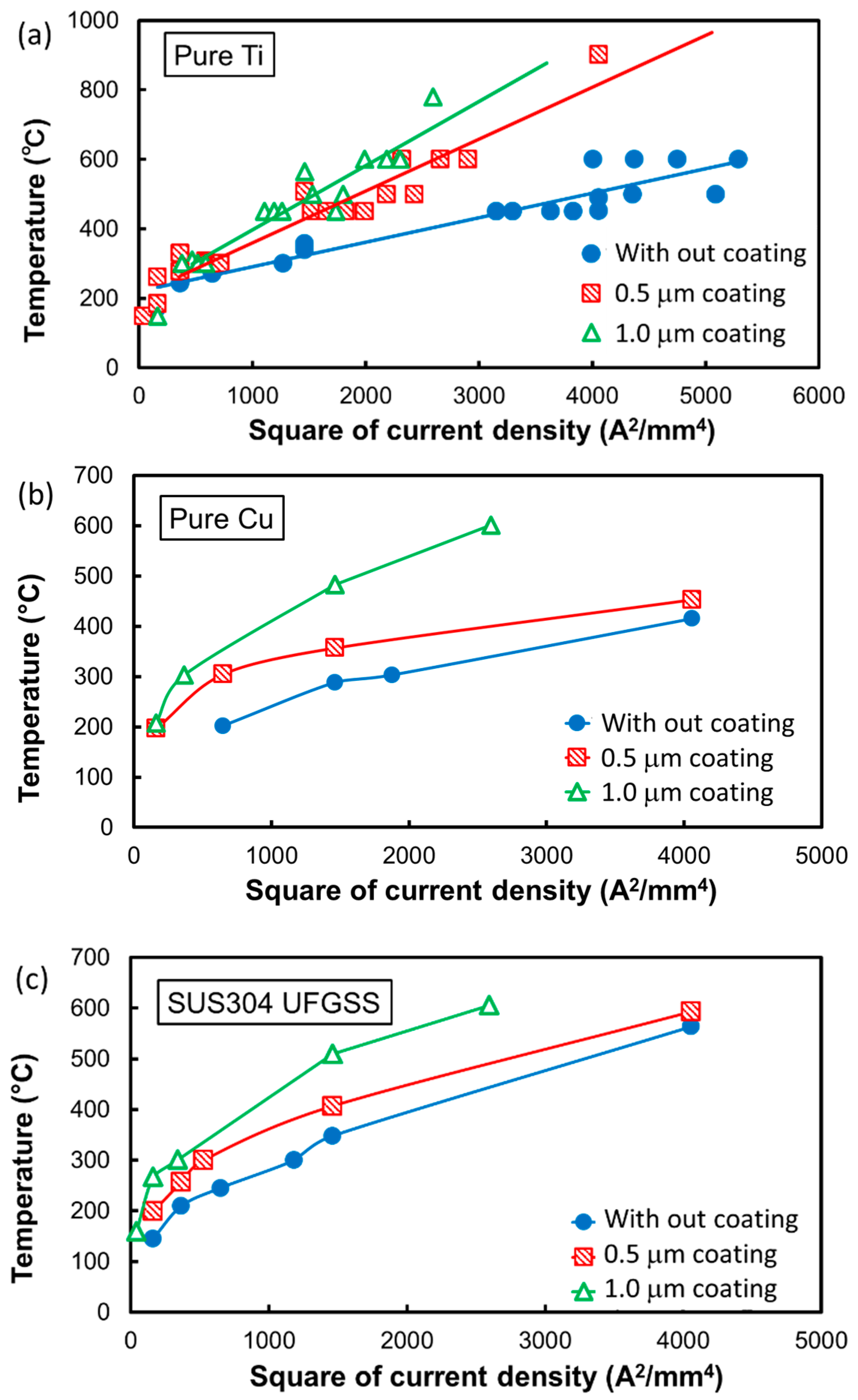
A layer with high electrical resistivity coated on the surface of the dies for the heating system was designed based on the prediction from FE analysis results. The desired temperature was achieved by selecting the appropriate thickness and electrical resistivity of the surface modification layer.
(2)
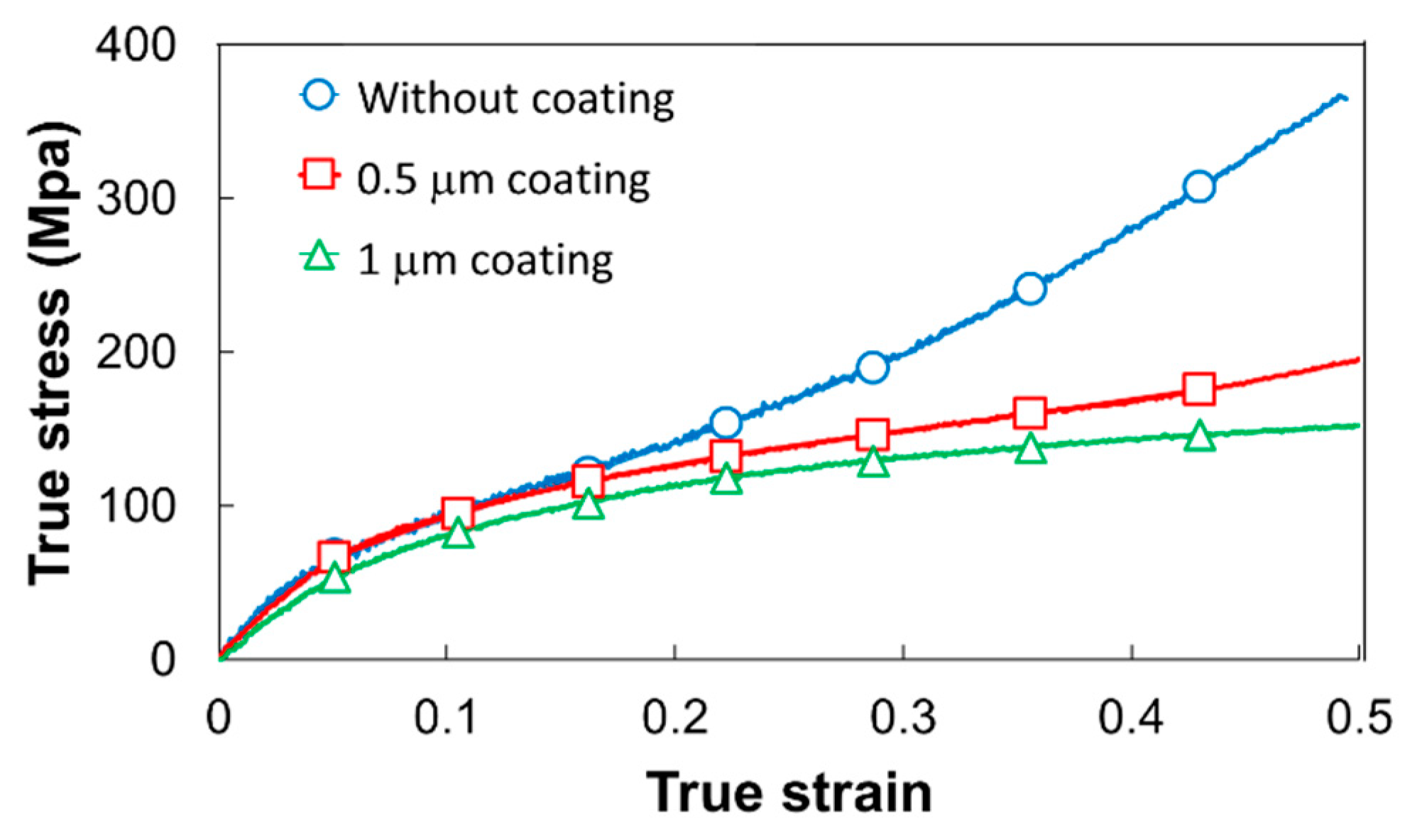
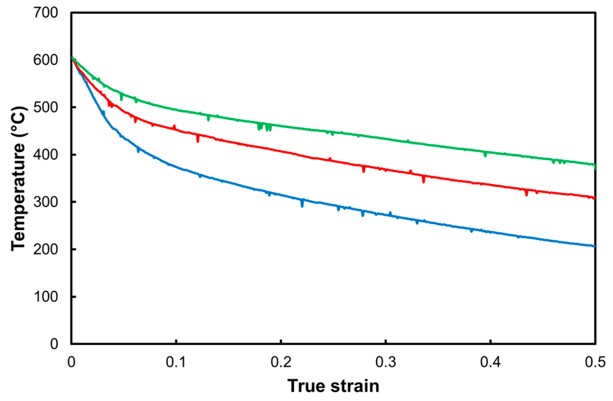
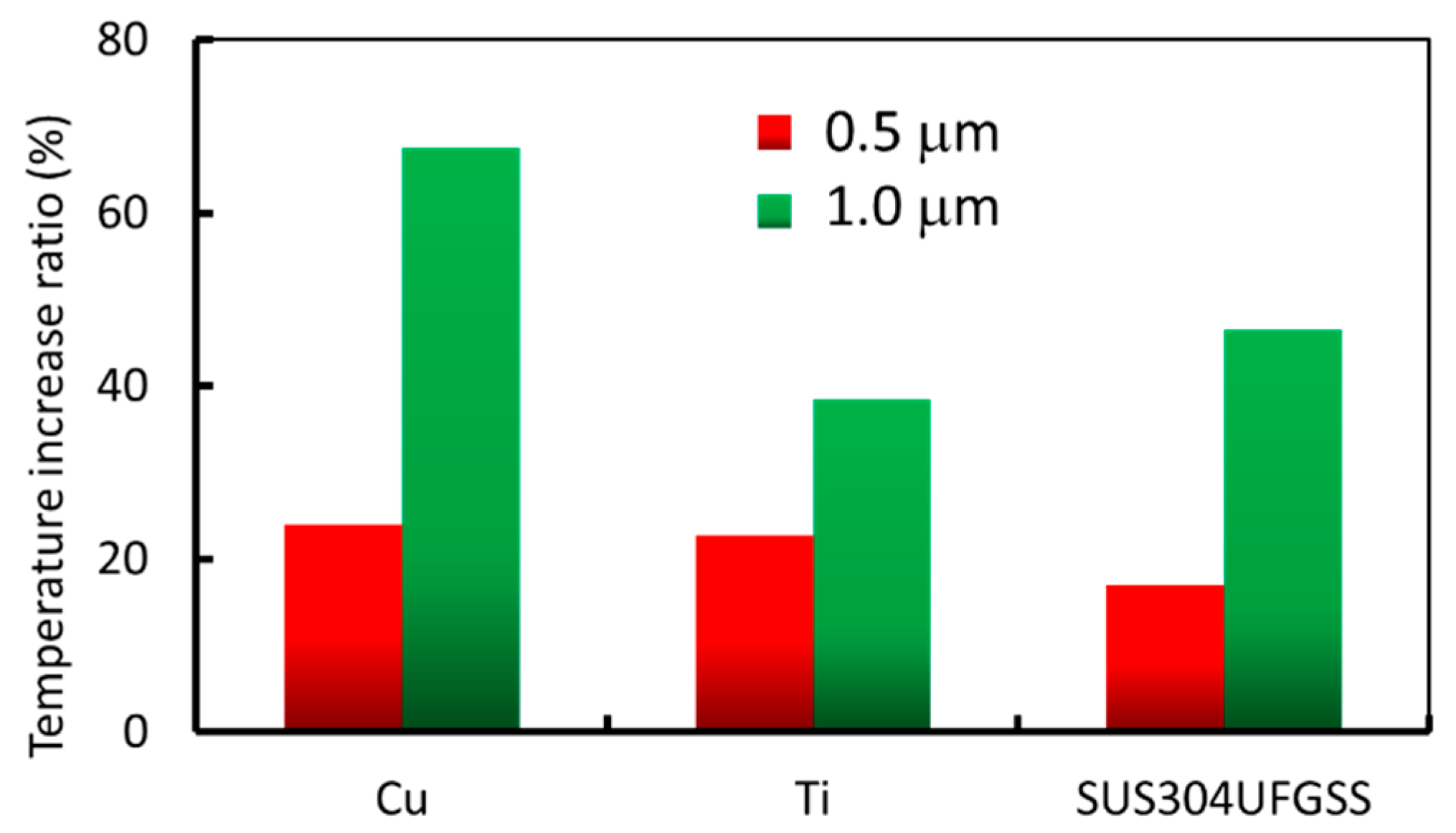
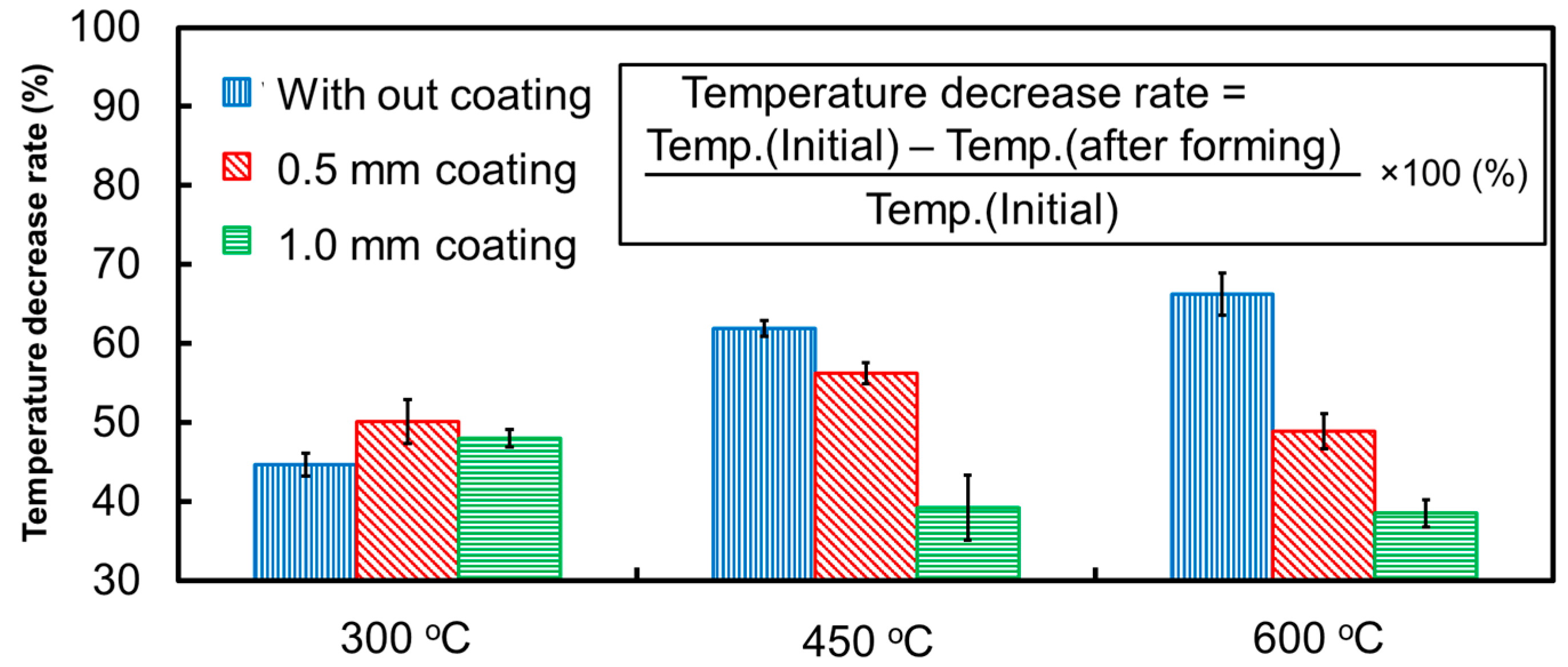
The superior heating efficiency of all the processed materials, namely, pure titanium, pure copper, and stainless steel, was confirmed by the compression test using the die coated with AlCrSiN. The heat generated from the surface layer of the die suppressed the temperature decrease of the workpiece during the compression deformation.
(3)
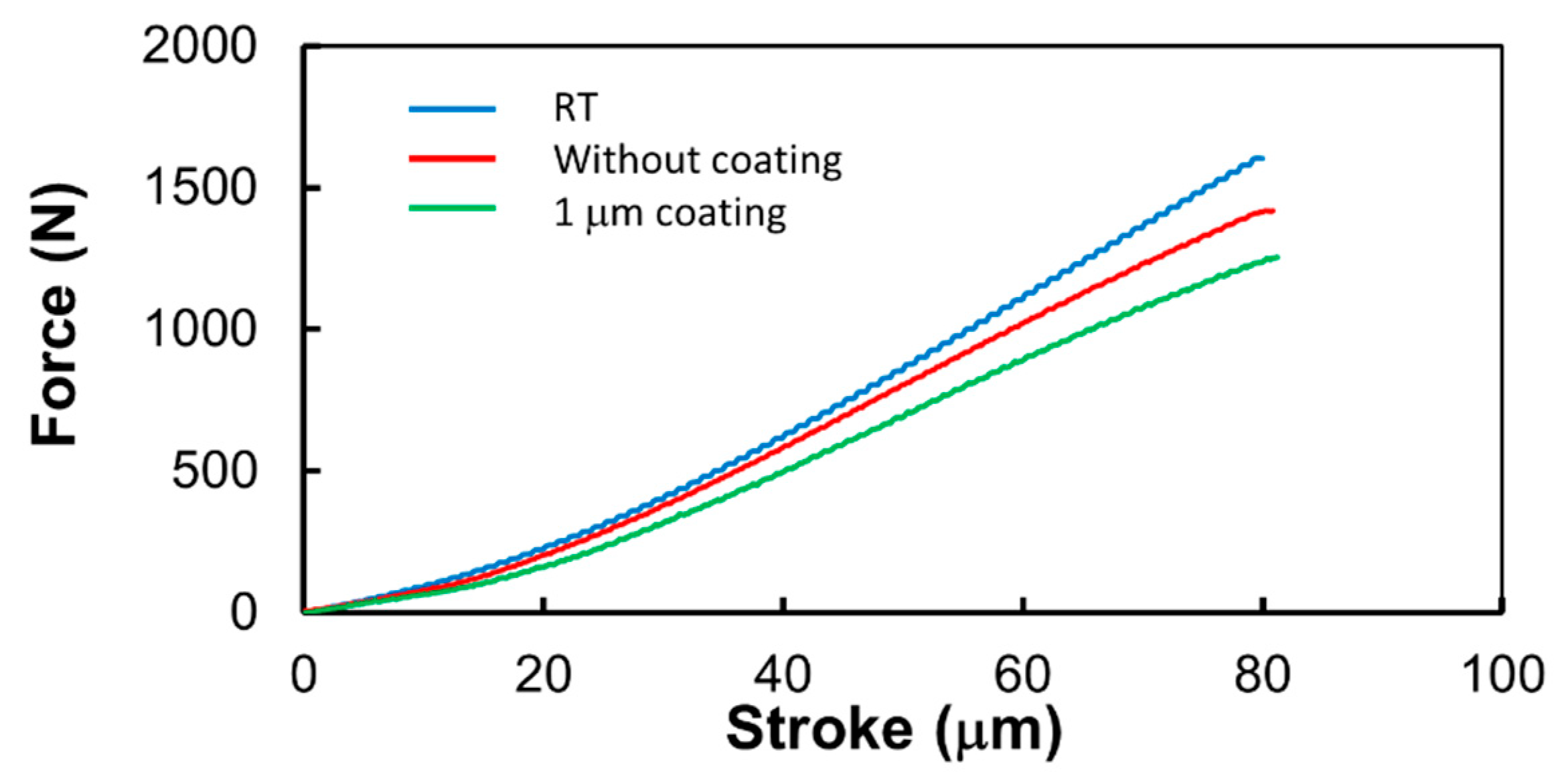
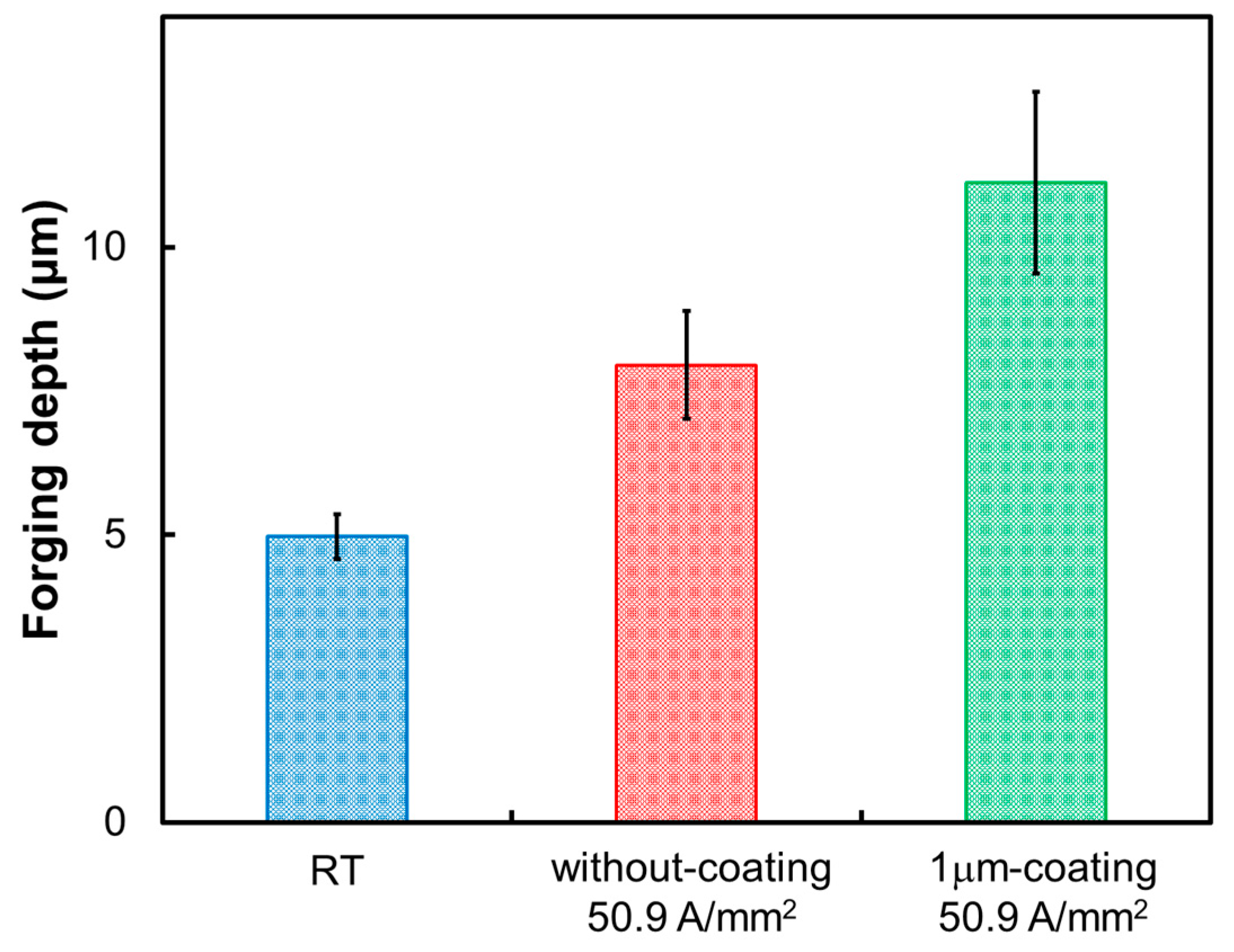
It was confirmed that the forging depth was increased by the surface modification in the electric heating while microforging a fine-grain stainless steel foil material with a thickness of 0.2 mm, which is difficult to heat using a conventional heating system.

Author Contributions

M.Y. designed and executed experiments. T.S. executed FE simulation and design of surface coating system.

Funding

This work was funded by JST foundation Grant-in-Aid for Scientific Research (B).

Acknowledgments

The authors thank Ryota Ogura for his contribution to the experimental implementation, Kaoru Ikenaga of Japan Electronics Co., Ltd., for cooperation with the coating of the dies using various ceramic materials, and Tomomi Shiratori for cooperation with the fabrication of microforged dies in the development of this electric heating system.

Conflicts of Interest

The authors declare no conflict of interest.

References

  1. Geiger, M.; Kleiner, M.; Eckstein, R.; Tiesler, N.; Engel, U. Microforming. CIRP Ann. 2001, 50, 445–462. [Google Scholar] [CrossRef]
  2. Vollertsen, F.; Biermann, D.; Hansen, H.N.; Jawahir, I.S.; Kuzman, K. Size effects in manufacturing of metallic components. CIRP Ann. 2009, 58, 566–587. [Google Scholar] [CrossRef]
  3. Engel, U.; Eckstein, R. Microforming—from basic research to its realization. J. Mater. Process. Technol. 2002, 125, 35–44. [Google Scholar] [CrossRef]
  4. Egerer, E.; Engel, U. Process characterization and material flow in microforming at elevated temperatures. J. Manuf. Process. 2004, 6, 1–6. [Google Scholar] [CrossRef]
  5. Peng, X.; Qin, Y.; Balendra, R. A numerical investigation to the strategies of the localised heating for micro-part stamping. Int. J. Mech. Sci. 2007, 49, 379–391. [Google Scholar] [CrossRef]
  6. Magee, J.; Watkins, K.G.; Steen, W.M. Advances in laser forming. J. Laser Appl. 1998, 10, 235. [Google Scholar] [CrossRef]
  7. Milenin, A.; Kustra, P.; Furushima, T.; Du, P.; Němeček, J. Design of the laser dieless drawing process of tubes from magnesium alloy using FEM model. J. Mater. Process. Technol. 2018, 262, 65–74. [Google Scholar] [CrossRef]
  8. Gillner, A.; Holtkamp, J.; Hartmann, C.; Olowinsky, A.; Gedicke, J.; Klages, K.; Bosse, L.; Bayer, A. Laser applications in microtechnology. J. Mater. Process. Technol. 2005, 167, 494–498. [Google Scholar] [CrossRef]
  9. Tanabe, H.; Yang, M. Design and evaluation of heat assisted microforming system. Steel Res. 2011, Special Edition, 1020–1024. [Google Scholar]
  10. Aoyama, T.; Shimizu, T.; Zheng, Q.; Yang, M. Effect of heating on springback in heat assisted micro bending. Adv. Mater. Res. 2014, 939, 409–414. [Google Scholar] [CrossRef]
  11. Zheng, Q.; Aoyama, T.; Shimizu, T.; Yang, M. Experimental and numerical analysis of springback behavior under elevated temperatures in micro bending assisted by resistance heating. Procedia Eng. 2014, 81, 1481–1486. [Google Scholar] [CrossRef]
  12. Zheng, Q.; Shimizu, T.; Yang, M. Scale effect on springback behavior of pure titanium foils in micro bending at elevated temperature. J. Mater. Process. Technol. 2016, 230, 233–243. [Google Scholar] [CrossRef]
  13. Zheng, Q.; Shimizu, T.; Yang, M. Numerical analysis of temperature distribution and its optimization for thin foils in micro deep drawing assisted by resistance heating. Steel Res. 2015. [Google Scholar] [CrossRef]
  14. Ogura, R.; Shimizu, T.; Shiratori, T.; Yang, M. Development of a novel resistance heating system for microforming by modifying surface of dies. Procedia Eng. 2017, 207, 1016–1021. [Google Scholar] [CrossRef]
  15. Zheng, Q.; Shimizu, T.; Yang, M. Effect of heat on tensile properties of thin pure titanium foils. Manuf. Rev. 2015, 2, 3. [Google Scholar] [CrossRef]
Figure 1. Concept of heating by surface-modified dies.
Metals 09 00440 g001
Figure 2. Schematic illustration of the finite element (FE) modeling of the resistance heating.
Metals 09 00440 g002
Figure 3. Analytical result of temperature distribution in 100 μm thick CrN0.6 layer heated for 60 s.
Metals 09 00440 g003
Figure 4. Predicted relationship between temperature and electrical resistivity.
Metals 09 00440 g004
Figure 5. (a) Image of the miniature servo press machine; (b) schematic illustration of the resistance heating system.
Metals 09 00440 g005
Figure 6. Stress–strain curves for pure titanium at 600 °C.
Metals 09 00440 g006
Figure 7. Variation of temperature as a function of strain.
Metals 09 00440 g007
Figure 8. Maximum temperatures plotted against square of current density for (a) pure titanium, (b) pure copper, and (c) SUS304 UFGSS.
Metals 09 00440 g008
Figure 9. Rate of temperature increase for different work materials.
Metals 09 00440 g009
Figure 10. Rate of temperature decrease for pure titanium.
Metals 09 00440 g010
Figure 11. (a) Electrical resistivity as a function of temperature in resistance heating of pure titanium, (b) temperature dependence of electrical resistivity of 1 μm AlCrSiN.
Metals 09 00440 g011
Figure 12. Forging punches: #1 uncoated, #2 AlCrSiN-coated.
Metals 09 00440 g012
Figure 13. Punch force during forging process for UFG stainless steel foil of 0.2 mm thickness.
Metals 09 00440 g013
Figure 14. Three-dimensional profiles of ring-shape forging. (a) RT; (b) without coating with 50.9 A/mm2; (c) 1 mm coating with 50.9 A/mm2.
Metals 09 00440 g014
Figure 15. Forging depth of UFG stainless steel foil.
Metals 09 00440 g015
Table 1. Conditions in the FE analysis.
PunchSUS420J2
DieSKD-11
WorkpieceMaterialSUS304
Thickness(mm)0.1
Surface modificationThickness(m)5, 50, 100
ShapeHollow
Outer/ Inner(mm)5 / 3.53
Initial temperature(°C)25
Atmosphere(°C)25
Current(A)40
FEM codeAbaqus6.17
Table 2. Resistivities of various materials used for surface modification.
MaterialFe4NZnOCrN0.6
Resistivity(cm)1622.2 × 1041.16 × 106
Table 3. Through-thickness resistances of ceramic-coated stainless steel and resistivities of ceramics.
OriginalTiAlNTiSiNAlCrSiN
Resistance (Ω)0.20.6–0.80.42300
Resistivity (μΩcm)-4 × 1091.7 × 1092 × 1012

