Article

Calculation of the Mixture Flow in a Low-Pressure Carburizing Process

1
Institute of Materials Science and Engineering, Lodz University of Technology, 1/15 Stefanowskiego Street, 90-924 Lodz, Poland
2
Seco/Warwick S.A., 8 Sobieskiego Street, 66-200 Świebodzin, Poland
*
Author to whom correspondence should be addressed.
Metals 2019, 9(4), 439; https://doi.org/10.3390/met9040439
Submission received: 19 March 2019 / Revised: 10 April 2019 / Accepted: 11 April 2019 / Published: 15 April 2019
(This article belongs to the Special Issue Surface Treatment Technology of Metals and Alloys)

Abstract

:
The right selection of carburizing gas flow rates in the low-pressure carburization process is a key factor in terms of its efficiency. However, a correct calculation of the amount of carburizing gas required for uniform carburization of parts, taking into account the process temperature and batch size, is still problematic. For this reason, modern carburizing processes are carried out using an excessive belaying flow of carburizing gases. In this work steel parts (16MnCr5) were carburized in a variable-flow carburizing process (960 °C) individually matched to each segment of saturation. The effect of the variable-flow on the microstructure, surface hardness, and case hardness depth was evaluated and compared to that of a control group. It was proven that the amount of the mixture used in the variable-flow carburizing process can be significantly reduced to 54% of that consumed during the regular constant-flow carburizing without affecting the properties of the hardened layer of the steel parts.

1. Introduction

Low-pressure carburizing (LPC) is a method of strengthening the surface of the steel. A vacuum of 1–10 hPa is created in the vacuum furnace chamber with the subsequent introduction of small amounts of carburizing gas at a temperature within the range of 900–1050 °C. Non-treated steel is post-cured in this environment for the time required to obtain the desired carbon profile. Due to the high temperature, the carbon transfer is more efficient in the case of the conventional carburizing method, thus leading to a shorter carburizing time. Yada and Watanabe reported an LPC process that did not pollute the environment, did not cause intergranular oxidation, and consumed less energy [1]. Additionally, Kula et al. demonstrated carburized steel after quenching and tempering to be multiple times harder than non-treated steel and, as such, to be industrially applicable in those processes where resistance to wear under working conditions is of significance [2].
The process of low-pressure carburizing is organized into cyclically repeating boost (saturation) and diffusion segments, where a boost segment is a characteristic of an intense surface and diffusion phenomena taking place in the part treated, while a diffusion segment solely consists of diffusion processes, with no carbon being delivered to the surface. During the boost segments, light hydrocarbons (methane, propane, acetylene, ethylene)—being a source of carbon—are dosed into the furnace chamber. Bensabath et al. described the phenomena of the decomposition of these compounds at high temperatures. Additionally, they indicated that hydrocarbon pyrolysis under low-pressure gas carburizing conditions might lead to gas phase reactions, which produce polycyclic aromatic hydrocarbons (PAHs) [3]. Mendiara et al. showed that increasing reaction temperature and the initial C2H2 concentration favors a formation of soot [4]. However, an optimization of the furnace performance is still carried out by using an empirical formula like the Harris equation [5] as a detailed vacuum carburizing prediction method has not yet been established.
Antes have proved that the correct selection of the carburizing mixture flow rate in the carburization chamber during the boost segment is of key importance for that segment efficiency [6]. An insufficient volume of carburizing gas in the carburization chamber results in a non-uniform carburized layer and, in consequence, a rejection of a batch of parts at the production stage. On the other hand, as Herring presented, an excess volume of such gas results in a deposition of carbon derivative substances accumulating in the furnace chamber, thus necessitating service break for the duration of its cleaning [7]. Therefore, a correct calculation of the amount of carburizing gas required for uniform carburization of parts, taking into account the process temperature and input (batch) size, remains problematic.
The EU 1558781 and US 7550049 patent publications describe a method of carburizing steel products applied in vacuum furnaces in an anaerobic atmosphere under reduced pressure, where the parts are saturated with carbon through continuous dosage of a carburizing atmosphere consisting of a mix of ethylene—or propane or acetylene—with hydrogen in the volume ratio of 1.5–10 for 5–40 min, flowing with constant efficiency throughout the whole duration of the carburization phase [8,9]. The EU 1558780 and US 7513958 patent publications describe a mixture for carburizing steel in a vacuum, containing a carbon carrier in the form of a mixture of ethylene and acetylene in a volume ratio of 0.1–2.0 and a modifier in the form of hydrogen in an amount of 0.7–1.5 times the carbon carrier volume, or in the form of ammonia in an amount of 0.7–5.0 times the carbon carrier volume, which is also dosed with constant efficiency during the saturation phase [10,11]. Additionally, Hermanowicz and Smolik report that it is possible to apply an impulse method of low-pressure carburizing, consisting of dosing carburizing gases during the saturation phase and then pumping the reaction products out during the diffusion phase [12].
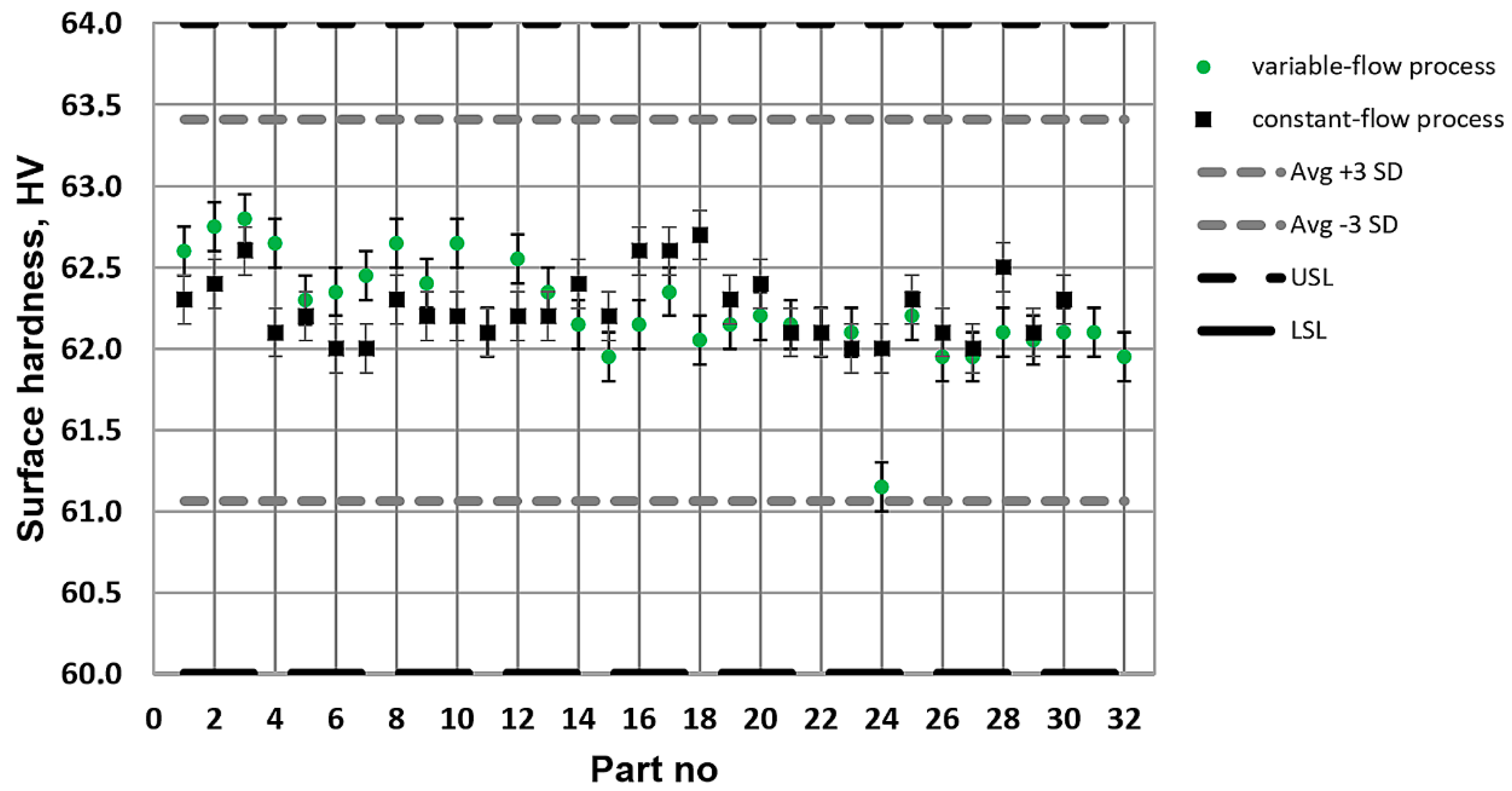
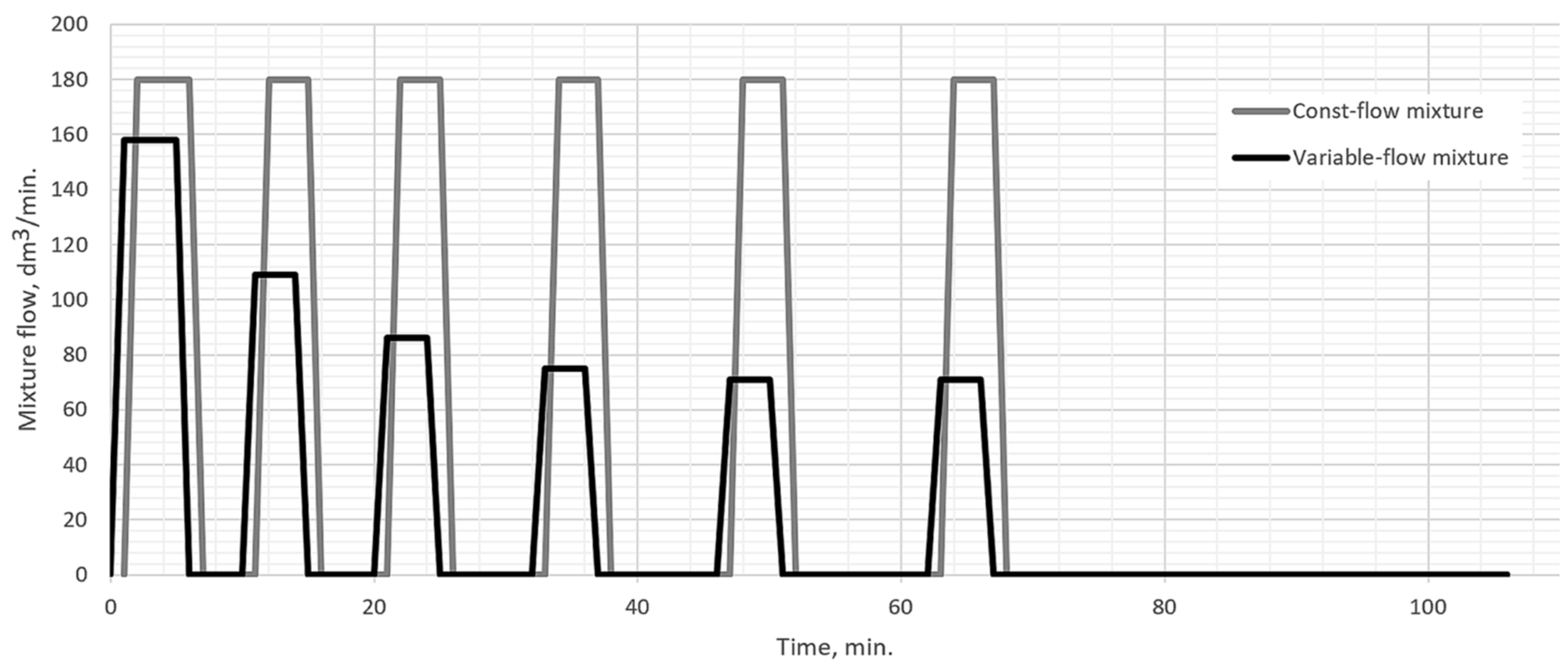
What is characteristic of all the low-pressure carburization methods presented is an introduction of carburizing gas or gas mixture with constant efficiency (constant flow), without taking into account the actual demand resulting from absorption of carbon in the material carburized (which fluctuates during the carburization process). At the same time, the dependency described by Fick’s first law indicates that the demand for carbon during a process decreases proportionally to an increase in carbon content in the material carburized. Therefore, this study aimed to establish whether the volume reduction of carburizing gases to the level given by Fick’s laws would have an impact on the properties of the hardened case obtained in regular low-pressure carburization processes. The following null hypotheses were tested: no differences in the properties of the surface layer (microstructure, surface hardness, case hardness depth) will be found between specimens that were carburized in a variable-flow carburizing process and those that were treated in a constant-flow carburizing process.

2. Low-Pressure Carburizing

Carburizing itself is a process where three fundamental phenomena take place (see Figure 1): transport of carbon atoms from the atmosphere to the steel surface (1); surface chemical reactions (absorption and adsorption) (2); diffusion of the carbon atoms absorbed deep into the material, consistently with the concentration gradient direction (3) [13]. Additionally, at a pressure of 1–10 hPa with small amounts of carburizing gas, the system conditions strive into the regime of Knudsen flow dynamics. However, under pressure conditions stated (>1 hPa), Knudsen parameter is <<0.01, which means that these phenomena still make a minor effect and can be neglected. Therefore, the total rate of carbon transfer from the atmosphere to steel is determined by the limiting process, which kinetically becomes a stage controlling the rate of carburizing. From that point of view, it is necessary to deliver carburizing gas to the steel surface at the rate adequate to the carbon demand to prevent it from becoming a factor slowing down the course of the process.
The constant value of the mass transfer coefficient is applicable in the majority of cases as, when the carbon potential approximates the carbon solubility limit in the austenite (with its content greater than 0.5 wt.%), the value of β coefficient becomes dependent on the temperature and has little relation to the carburizing gas composition [15]. However, hydrocarbon gases supplied to the furnace chamber during the boost stage create a very high carbon potential which may cause a formation of soot and tar. Therefore, the mass balance boundary condition is not applicable to the carburization process. However, a dependency can be applied that describes the constant surface flux. It is assumed that the amount of carbon produced through surface reactions is equal to the mass flow rate for diffusion, as described by Fick’s first law [15]:
J | x = 0 = D | x = 0 d C d x | x = 0
where x = 0 at the gas-steel interface.
At optimization of industrial carburization processes is usually carried out using the trial and error method. As well as being time-consuming and expensive, this approach provides results that are suboptimal at best [16]. An additional factor making a selection of the right flow difficult is the fact that the gas introduced into the carburization chamber does not fully dissociate. The degree of dissociation depends on the temperature and changes in time, and its value can only be determined experimentally [6].
In conventional atmospheric carburizing, it is assumed that the input absorbers constitute no more than 10% of carbon available from the carburizing atmosphere. Consequently, when calculating the flow value, at last, a tenfold excess is specified. In low-pressure carburizing, the amount of carburizing mixture applied is three to four times greater. The method of calculating the carburizing gas flow rate for acetylene has suggested by Antes, with an indication that this procedure requires familiarity with the curve of a fraction of acetylene dissociated as a function of temperature and time [6]. Once calculated, the flow value remains constant for all the boost stages. Simultaneously, the absorptivity of the carburized material decreases with the decrease of the material’s carbon concentration gradient. It is therefore important to elaborate a method that will adjust the flow value individually to each boost segment and ensure maximum utilization of carbon (reduction of its excess) delivered by the carburizing gas at each stage of the process. At the same time, it has to ensure the supply of a sufficient amount of carbon to the surface, in order not to become a parameter that limits the rate of the process.

3. Materials and Methods

Three thousand two hundred forty identical machine parts made of 16MnCr5 steel (0.17%C, 0.27%Si, 1.15%Mn, 0.95%Cr, 0.3%Ni, 0.05%Al, 0.3%Cu) of a total surface area of 21.8 m2, were evenly distributed on nine trays and placed inside a vacuum furnace chamber (Seco/Warwick, Świebodzin, Poland). The parts were subjected to a low-pressure carburizing process at a temperature of 960 °C, in a 2:2:1 mixture of acetylene, ethylene, and hydrogen. After carburizing, the parts were subjected to oil quenching and tempering at a temperature of 165 °C. From the entire input volume, 32 parts were randomly selected and subjected to metallographic examination. Additionally, the surface hardness and case hardness depth of the parts were measured.
Low-pressure carburizing was carried out in 6 “boost-diffusion” cycles (Table 1). In the boost stages, individual flows of carburizing gases were applied, that were consistent with the demand for the mixture at a given stage, determined using the following formula [17]:
F b = 22.4 m C 7,870,000 C x t b S
where mC is the mass of carbon in 1 mole of the carburizing mixture, tb—boost segment duration, S—carburization area, C x —amount of carbon absorbed by the surface areas during a boost-diffusion segment. Given the mixture in the carburization chamber being only partially dissociated, the calculated flow value was divided by the degree of mixture dissociation determined according to the procedure of Antes [6]. After carburizing, the parts were quenched and tempered and then examined with regard to metallography, surface hardness, and thickness of the hardened case.
The values measured were compared to those obtained in a references process, with a constant flow of mixture at a level of 180 dm3/min, applied in the industrial practice. The parameters expected were those of the correct structure of a given part (martensite in the hardened later with retained austenite content of <10%, and bainite in the core), uniform thickness of the hardened case of above 0.8 mm (but not by more than 0.3 mm), and hardness of the hardened and tempered case of above 60 HRC (but not by more than 4 HRC). The surface hardness and case hardened depth test results were statistically analyzed with the U-Mann Whitney’s test (α = 0.05) (see Figure 2).

4. Results

Metallographic observations carried out with the use of an optical microscope (Nikon, Tokyo, Japan) confirmed the presence of a tempered martensite structure in the hardened layer, with a minor amount of retained austenite (<5%). A uniform bainitic structure was observed in the core (Figure 3).
The average surface hardness of all the parts examined amounted to 62.2 ± 0.4 HRC and fit within the range of 60–64 HRC (Figure 4). The average thickness of the hardened case (with the criterion of 550 HV) for all the parts examined was 0.88 ± 0.03 mm and also fit within the expected range of 0.8–1.1 mm (Figure 5 and Figure 6). The statistical analysis of the results of the surface hardness test indicate that the type of LPC process does not affect surface hardness (P > 0.05). The statistical analysis of the results of the CHD test would affect the thickness of the hardened case. However, as it was mentioned above, for all the parts examined CHD fit within the expected range of 0.8–1.1 mm.

5. Discussion

To verify the correctness of the method of selection of the carburizing mixture flow rate, a low-pressure carburizing process was performed, with subsequent quenching and tempering. The amount of carburizing gases was indicated individually for each boost stage. The parts, after processing, were examined with regard to their structure, hardness, and the thickness of the hardened case. It was confirmed that the correct microstructure was obtained in the parts (tempered martensite in the carburized layer and bainite in the core). All the samples achieved a satisfactory surface hardness (62.2 ± 0.4 HRC) and hardened case thickness (0.88 ± 0.03 mm). Additionally, based on the statistical three-sigma rule, it is expected that 99.7% of the whole series of 3240 parts exhibit surface hardness within a range of 61.0–63.4 HRC and hardened case thickness within a range of 0.80–0.97 mm. These results entirely meet the requirements assumed.
In the case of samples 1–4 that were located on the first tray in the chamber, an increased layer hardness and thickness were found. The authors of the work believe that it is related to the distribution of carburizing nozzles inside the furnace chamber. Tray 1 was located on the top of the input and was situated closer to the nozzle exhaust when compared to the rest of the input. As a result, it was absorbing more carbon that the parts located in the middle of the input. However, this had no impact on the results of the examinations as the parameters of these parts still fitted within their expected ranges.
In the experiment, the amounts of carburizing gas were adjusted individually to every boost stage, and they led to satisfactory results of the process, comparable to those of conventional low-pressure carburizing processes. No differences in the properties of the surface layer were found between specimens that were carburized in a variable-flow process and those that were treated in a constant-flow process. It was, therefore, demonstrated that the process could be carried out efficiently with a simultaneous significant reduction of the amount of carburizing gases. The value of reduction depends on the temperature and the method of the process organization. In the studied case, the amount of the gas mixture used was 46% lower than that applied in the traditional process (Figure 7).

6. Conclusions

The amount of carburizing gas in the low-pressure carburizing process can be significantly limited. The value of reduction depends on the temperature and the method of organization of the process. By an individual selection of carburizing gas flow rates for each boost segment the amount of the mixture used for the variable-flow carburizing was 46% lower than that used during the regular constant-flow carburizing. It is a completely new approach to the organization of the process, not described in the literature so far. The individual selection of carburizing gas flow rate for each boost segment ensures a significant reduction of the gas amount without affecting the properties of the hardened case of the parts treated.

Author Contributions

Conceptualization, E.W.-K. and M.K.; Data curation, M.S.; Formal analysis, M.K.; Investigation, M.S. and A.B.; Methodology, E.W.-K. and M.K.; Project administration, P.K.; Resources, M.S. and A.B.; Software, E.W.-K.; Supervision, P.K.; Validation, M.K. and P.K.; Visualization, A.B.; Writing—original draft, E.W.-K.; Writing—review & editing, P.K.

Funding

This research was funded by the Polish National Centre for Research and Development, grant number POIR.04.01.04-00-0087/15.

Conflicts of Interest

The authors declare no conflict of interest. The funders had no role in the design of the study; in the collection, analyses, or interpretation of data; in the writing of the manuscript, or in the decision to publish the results.

References

  1. Yada, K.; Watanabe, O. Reactive flow simulation of vacuum carburizing by acetylene gas. Comput. Fluids 2013, 79, 65–76. [Google Scholar] [CrossRef]
  2. Kula, P.; Pietrasik, R.; Dybowski, K. Vacuum carburizing—Process optimization. J. Mater. Process. Technol. 2005, 164–165, 876–881. [Google Scholar] [CrossRef]
  3. Bensabath, T.; Monnier, H.; Glaude, P.-A. Detailed kinetic modeling of the formation of toxic polycyclic aromatic hydrocarbons (PAHs) coming from pyrolysis in low-pressure gas carburizing conditions. J. Anal. Appl. Pyrolysis 2016, 122, 342–354. [Google Scholar] [CrossRef]
  4. Mendiara, T.; Domene, M.P.; Millera, A.; Bilbao, R.; Alzueta, M.U. An experimental study of the soot formed in the pyrolysis of acetylene. J. Anal. Appl. Pyrolysis 2005, 74, 486–493. [Google Scholar] [CrossRef]
  5. Harris, F.E. Case depth—An attempt at a practical definition. Met. Prog. 1943, 44, 265–272. [Google Scholar]
  6. Antes, H.W. Calculating the gas flow rate for vacuum carburization. Heat Treat. Prog. 2005, 8, 51–53. [Google Scholar]
  7. Herring, D.H. A case for acetylene based low pressure carburizing of gears. Therm. Process. Gear Solut. 2012, 9, 40–45. [Google Scholar]
  8. Kula, P.; Olejnik, J.; Heilman, P. Method for Under-Pressure Carburizing of Steel Workpieces. EU Patent EU 1558781, 25 October 2006. [Google Scholar]
  9. Kula, P.; Olejnik, J.; Heilman, P. Method for Under-Pressure Carburizing of Steel Workpieces. U.S. Patent US 7550049, 23 June 2009. [Google Scholar]
  10. Kula, P.; Olejnik, J.; Heilman, P. Hydrocarbon Gas Mixture for the Under Pressure Carburizing of Steel. EU Patent EU 1558780, 15 August 2007. [Google Scholar]
  11. Kula, P.; Olejnik, J.; Heilman, P. Hydrocarbon Gas Mixture for the Under-Pressure Carburizing of Steel. U.S. Patent US 7513958, 7 April 2009. [Google Scholar]
  12. Hermanowicz, P.; Smolik, J. Vacuum carburizing of low carbon steel DC4 in atmosphere composed by aliphatic hydrocarbons. Problemy Eksploatacji 2008, 1, 21–34. (In Polish) [Google Scholar]
  13. Turpin, T.; Dulcy, J.; Gantois, M. Carbon diffusion and phase transformations during gas carburizing of high-alloyed stainless steels: Experimental study and theoretical modeling. Metall. Mater. Trans. A 2005, 36, 2751–2760. [Google Scholar] [CrossRef]
  14. Karabelchtchikova, O. Fundamentals of Mass Transfer in Gas Carburizing. Ph.D. Thesis, Worcester Polytechnic Institute, Worcester, MA, USA, 18 December 2007. [Google Scholar]
  15. Wei, Y.; Wang, G.; Sisson, R.D.; Bernard, B.; Poor, R. Intelligent heat treating: Simulation of carburizing process. In Proceedings of the 26th ASM Heat Treating Society Conference, Cincinnati, OH, USA, 31 October–2 November 2011; ASM International: Cincinnati, OH, USA, 2011; pp. 91–98. [Google Scholar]
  16. Kula, P.; Dybowski, K.; Wolowiec, E.; Pietrasik, R. Boost-diffusion vacuum carburizing—Process optimisation. Vacuum 2014, 99, 175–179. [Google Scholar] [CrossRef]
  17. Korecki, M.; Wołowiec-Korecka, E.; Sut, M. Low-Pressure Carburizing Method (LPC). Poland Patent P.424224, 1 August 2018. [Google Scholar]
Figure 1. Mechanisms of carbon transfer during carburizing and their primary control parameters: the mass transfer coefficient (β) defining carbon atom flux (J) from the atmosphere to the steel surface and the diffusion coefficient of carbon in steel (D) at austenitizing temperatures [14].
Metals 09 00439 g001
Figure 2. Block scheme of the experimental system: test group (32 parts) randomly taken from 3240-part batch (resulting from variable-flow LPC process), investigated and compared with the control group (resulting from constant-flow LPC process).
Metals 09 00439 g002
Figure 3. Structure of parts resulting from variable-flow process. (a) Surface of part. Structure: tempered martensite; retained austenite share below 10%. Magnification: ×400. Etching: 3% HNO3/ethanol; (b) Core of part. Structure: bainite. Magnification: ×400. Etching: 3% HNO3/ethanol.
Metals 09 00439 g003
Figure 4. Surface hardness of parts resulting from variable-flow and constant-flow processes (LSL, USL—lower and upper specification limit).
Metals 09 00439 g004
Figure 5. The depth of the hardened case of parts resulting from variable-flow and constant-flow processes (LSL, USL—lower and upper specification limit).
Metals 09 00439 g005
Figure 6. Surface hardness and depth of the hardened case of parts resulting from variable-flow and constant-flow processes.
Metals 09 00439 g006
Figure 7. The amounts of carburizing gases used in the processes with constant and variable mixture flows.
Metals 09 00439 g007
Table 1. Organization of the low-pressure carburizing process including carburizing mixture flow.
No.Boost (min)Diff (min)Pressure (hPa)Flow in the Boost Stage (dm3/min)
1556.0/0.3158
2476.0/0.3109
3486.0/0.386
44106.0/0.375
54126.0/0.371
64406.0/0.371

