Abstract
Rolling back-up rolls require high fracture toughness, particularly in the shaft portion, and high-hardness in the sleeve portion. The rolls are classified into two types; one is an integrated type and the other is a shrink-fitted type consisting of a sleeve and a shaft. The shrink-fitted roll has several advantages, for example, suitable materials can be chosen and the shaft can be reused by replacing the damaged sleeve. However, during use if the residual permanent deflection occurs, the roll cannot be used anymore. In this paper, an elastic-contact finite element method FEM analysis is performed to explain the residual permanent deflection mechanism. It is found that the quasi-equilibrium stress zone with the residual displacement causes the permanent slippage in the axial direction. In a similar way, the interface creep in the circumferential direction can be also explained from the quasi-equilibrium stress zone with the residual displacement.
Keywords:
rolling; roll; shrink fitting; sleeve; finite element method; friction joint; slippage; interfacial creep 1. Introduction
The rolling rolls require the high toughness shafts to support large rolling load. Also, the rolls require the high hardness surface to prevent spalling caused by the cyclic contact loading [1,2,3]. Currently most of the rolls are classified into integrated type, but another type sleeve rolls are also developed by shrink fitting the sleeve to the shaft as shown in Figure 1 [4,5]. In this sleeve roll, suitable materials can be chosen independently for the shaft and the sleeve. And the shaft can be reused by replacing the damaged sleeves. Therefore, there are some advantages over integrated type.
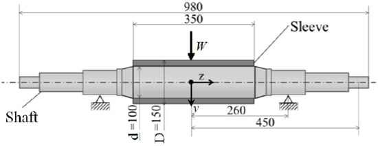
Figure 1.
Dimensions of back up roll simply supported [mm].
The rolling rolls also require the straightness roll axis center within 0.02 mm error at the end of shaft. Therefore, if a permanent residual roll deflection occurs during the operation, the sleeve constructed rolls cannot be used anymore. In the previous study [6,7,8,9,10,11,12,13,14,15,16,17,18,19,20,21,22,23], the residual deflection was investigated experimentally for small rolls. However, the residual deflection was not compared with the deflection due to the standard load and therefore the deflection mechanisms has not been sufficiently clarified. To prevent the residual deflection, it is necessary to explain the residual deflection mechanism of the sleeve constructed roll although the experimental study needs a lot of time and cost. In this study, therefore, numerical simulation will be performed to realize this phenomenon by applying contact FEM elastic analysis. After confirming the simulation method, the results will be compared with the experiment result. Then, the mechanism will be elucidated.
2. Simulation in Comparison with Experiment
2.1. Previous Experiment
Figure 1 shows the sleeve constructed roll previously studied [6,7,8,9]. The sleeve was assembled to the shaft by shrinkage fitting. Then, the residual deflection was studied experimentally by Shimoda et al. [6,7,8,9]. The ratio of the sleeve thickness to the shaft diameter is slightly larger than the actual ratio. And the ratio of the trunk length to the trunk diameter is larger than the actual ratio in order to clarify the influence of the length [9]. To measure deflection, a 980 kN hydraulic press machine was used by applying 3 point bending method. To measure the residual deflection, a non-adhesive resistor linear transducer and an automatic equilibrium recorder were combined to improve the measurement accuracy. And a stylus method was used to record the distance between the roll axis parallel line and the roll. After removing the load, during the small roll rotation at a constant speed of 6 rpm, the residual deflection in the load direction was measured at the equally divided points in the axial direction.
2.2. Analysis Method of Residual Deflection
As shown in Figure 1, in the shrinkage fitted sleeve roll, the distributed load in actual rolling is replaced by the concentrated load W. In Figure 1, steel is used for both the shaft and the sleeve. Define the shrink fitting ratio δ/d as the ratio of the shrink fitting margin δ to the sleeve inner diameter d = 100 mm. Reference 6 indicates that the effect of δ/d on the residual deflection becomes smaller if shrink fitting ratio δ/d is larger than a certain value. The value used in this study δ/d = 1.0 × 10⁻³ is within this range, and this value δ/d = 1.0 × 10⁻³ was used in the experiment. Shrink fitting ratio δ/d can be provided in finite element method FEM simulation by using the option “interference closure” in MSC Marc /Mentat 2012 (Marc 2012, MSC.Software Corporation, Santa Ana, CA, USA). After the shaft and sleeve are assembled the tolerances δ can be applied by using this option.
Table 1 shows the mechanical properties of steel used in the model roll. In the analysis, the deflection in the y-direction is evaluated along the roll central axis under loading and unloading by varying load W and friction coefficient μ. In reference 6, it was confirmed that the experiment was conducted within the elastic range. Therefore FEM simulation is performed as three-dimensional contact elastic analysis. Concentrated load was used in the experiment in reference 7. In contact FEM analysis, it is known that the Coulomb friction model can be widely used for most practical applications except for bulk forming as encountered in e.g., forging processes. Three types of Coulomb friction models are available, that is, arctangent model, stick-slip model and bilinear model. However, it is known that the arctangent model is unsuitable for estimating the typical relative sliding velocity priori when the sliding velocity varies largely during the analysis. Also, the stick-slip model needs a large amount of data to be determined from repetitive calculation process. In this study, therefore, the bilinear model is applied since the friction force is simply determined from the displacement.

Table 1.
Material properties of Cr-Mo steel shaft and sleeve.
Figure 2 shows the analysis model. Hexahedral primary element having 8 nodes is used with a minimum dimension of 1.25 mm, and the number of total nodes is 117,900 and the number of total elements is 78,600. The mesh effect of FEM on the results is less than a few percent. Considering the symmetry, half of the roll is analyzed.
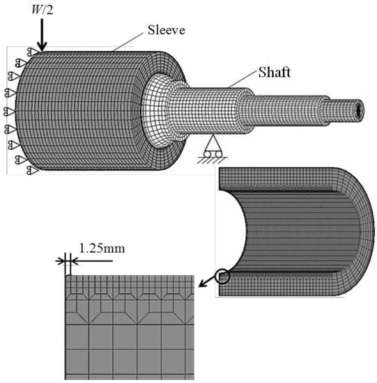
Figure 2.
Analytical model and FEM mesh for back up roll.
3. Analysis Results for Residual Deflection
3.1. Deflection under Loading and Residual Deflection after Unloading
Figure 3 shows the analysis results by changing the friction coefficient μ under the fixed load W = 294 kN. From Figure 3, it can be seen that the deflection increases with decreasing μ. Figure 4 shows the obtained residual deflection after removing load W = 294 kN. In Figure 4, the experimental results by Shimoda et al. [6,7,8,9]. With μ = 0.2 are also plotted. It is seen that the simulation result coincides with the experimental result within 15 % error at the center of the roll. In Figure 4, since the detail of the experimental deflection shape was not indicated in the previous study, the deflection shape cannot be compared.
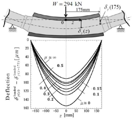
Figure 3.
Deflection at W = 294 kN.
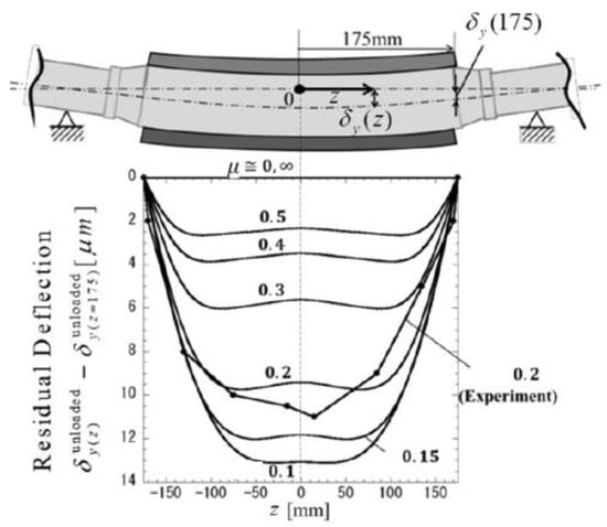
Figure 4.
Residual deflection after unloaded from W = 294 kN.
When μ = 0, the shaft and the sleeve can deform independently. Since they do not interfere each other in the axial direction, the residual deflection does not occur. When μ = ∞, the shaft and the sleeve behave as an integrated unit, so that no residual bending occurs. As shown in Figure 3 and Figure 4, when μ = 0.2, the maximum residual deflection 9.7 μm occurs, which is about 10 % of the loading deflection.
3.2. Effect of the Friction Coefficient and the Magnitude of Load on the Residual Deflection
Figure 5 shows the difference of the residual deflection Δ by varying μ under W = 147 kN, 294 kN, 588 kN. From Figure 5, it is seen that the residual deflection increases with increasing the load W. The residual deflection Δ increases with increasing μ initially and has a peak value at μ = 0.1–0.2 and finally decreases. When W = 147 kN, the peak value appears at μ ≅ 0.1. When W = 294 kN, the peak value appears at μ ≅ 0.12, and when W = 588 kN, the peak value appears at μ ≅ 0.17.
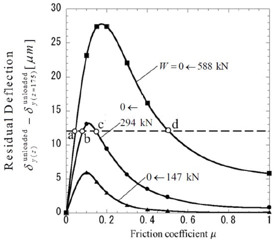
Figure 5.
Effect of friction coefficient μ on the residual deflection of contact area.
4. Discussion of Residual Deflection Generation Mechanism
4.1. Relative Slippage of the Sleeve to the Shaft
The simulation and experimental results suggested that the residual deflection may be controlled by the friction coefficient, the frictional surface stress and the slip condition. Consider the relative sllipage between sleeve and shaft defined in Figure 6. The residual relative slippage can be defined as the relative displacement of the sleeve in the z-direction with respect to the shaft after removing the load.
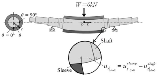
Figure 6.
Definition of relative displacement between sleeve and shaft.
Figure 7 shows the relative slip distribution at the sleeve end at z = 175 along the circumferential direction. From Figure 7, we will focus on the maximum value of the residual relative slippage generated at the lower side of the roll θ = 0°. Figure 8 shows the effect of the friction coefficient on the residual relative slippage at the lower side of the roll θ = 0°after removing the load when W = 147 kN, 294 kN, 588 kN. From Figure 5 and Figure 8, when W = 294 kN, the residual deflection shows the maximum value at μ = 0.12 and the residual relative slippage shows the maximum at μ = 0.08. Both values are relatively close. Also, similar variations can be seen in the region where 0.3. In this way, it may be concluded that residual deflection and relative slip have almost the same trend.
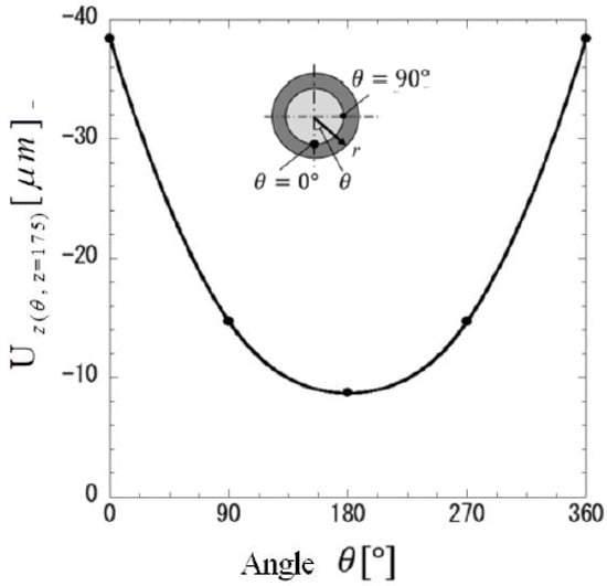
Figure 7.
Distribution of relative displacement along circumference at roll end.
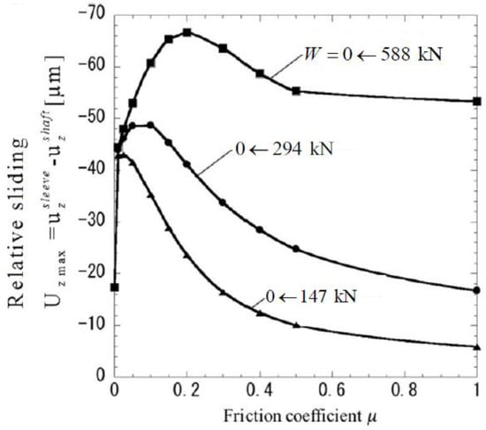
Figure 8.
Effect of friction coefficient μ on maximum relative displacement after unloaded.
4.2. Residual Deflection Caused by the Stress State along the Shrinkage-Fitting Surface
From the above discussion, the relative slippage may be involved in the occurrence of residual deflection. In this section, the stress state along the joint surface of the roll will be investigated and the slippage condition along the surface will be clarified. As shown in Figure 5, under W = 588 kN, the same residual deflection Δ = 12 μm can be obtained at Point “a” corresponding to μ = 0.04 and Point “d” corresponding to μ = 0.5. In a similar way, under W = 294 kN, the same residual deflection Δ = 12 μm can be obtained at Point “b” corresponding to μ = 0.07 and Point “c” corresponding to μ = 0.15. Those four points a, b, c, d have the same residual deflection but different load or different friction coefficient.
Figure 9 shows the shear stress distribution τ as a solid line and the friction stress distribution μσ as a broken line at Points a, b, c, d. In Figure 9, the peak values of τ around z = 0 mm and z = 175 mm may include some numerical errors as shown in Figure 9a. In this study, the region Lu where τ < |μσ| and the region Lb where τ ≅ |μσ| are considered. The region around z = 0 mm and z = 175 mm is not considered since the effect is negligible. The stress distribution is represented by the point deflection at the opposite side to the loading point θ = 0° and r = 50 mm where the relative slippage appears most. Here, and in the coordinate system are denoted by τ and σ, respectively.
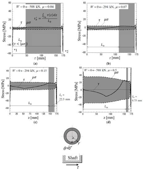
Figure 9.
Shear stress τ and frictional stress μσ along shaft surface contacted with sleeve after unloaded; (a) Point a, W = 0 ← 588 kN, μ = 0.04; (b) Point b, W = 0 ← 294 kN, μ= 0.07; (c) Point c, W = 0 ← 294 kN, μ = 0.15; (d) Point d, W = 0 ← 588 kN, μ = 0.5 (*1: Error due to boundary condition, *2: Error due to end effect and boundary condition).
The contact surfaces are divided into two regions. One is the region Lu where τ < |μσ|. The other is the region Lb where τ ≅ |μσ|. Here, within 1 MPa difference is regarded as τ ≅ |μσ| by considering the numerical accuracy. The region Lb denotes “quasi-equilibrium stress zone”. The quasi-equilibrium stress zone is closely related to the residual deflection. This is because no residual deflection without Lb.
Next, the relevance between the residual deflection and Lb is examined. Table 2 shows that the same residual deflection = 12 μm can be obtained under which condition. Here, the values of W, μ, Lb, (Lb × *), (Lb × * × (Lu + Lb/2)) are indicated. Those values are corresponding to Figure 9, which indicates the state of Points a, b, c, d in Figure 5. Here, * denotes the average shear stress in Lb. In Table 2, it is seen that the value of (Lb × * × (Lu + Lb/2)) is almost constant within 10% error.
Table 2.
Shearing force and when Δ = 12 μm for a, b, c, d in Figure 5.
Here, Lb denotes the region where ≅ || is satisfied within 1 error. As shown in Figure 9d, the region of τ ≅ |μσ| looks larger than Lb = 8.75 mm. Suitable definition Lb should be considered in the future study. Although the quantitative discussion is not sufficient, the frictional force Lb × * generated at the contact surface strongly relates to the magnitude of residual deflection. Simple relation cannot be found between Lb and the magnitude of the residual relative slip.
4.3. Roll Deflection during Unloading Process and Stress Change along the Shrink Fitted Surface
In this section, the residual deflection is analyzed during unloading after loading. The stress change is also investigated to find the residual deflection generation mechanism.
Figure 10 shows the deflection W the load W = 588 kN is applied and being removed gradually. Here, by considering Point “d” in Figure 5, W = 588 kN with μ = 0.5 is initially applied and gradually decreases as W = 294 kN, 196 kN, 98 kN, 49 kN. In Figure 10 the deflection based on the residual displacement is nearly proportional to the remaining load during unloading. The deflection due to W = 294 kN during unloading process after applying W = 588 kN is about 11% larger than the deflection due to W = 294 kN during loading process from W = 0. This is because the deflection is affected by the loading history in a similar way of the residual deflection.
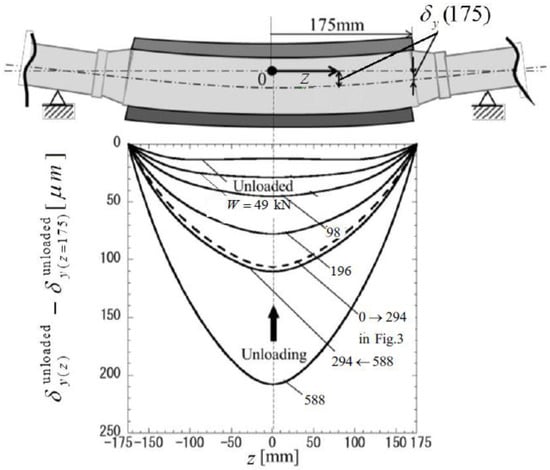
Figure 10.
Deflection and residual deflection on arbor when load was reduced from 588 kN (μ = 0.5).
Figure 11 shows the shear stress distribution in the z-direction along the lower side of the sleeve and the shaft during unloading process. In Figure 11, based on the residual stress distribution after unloading, the stress distribution shapes are almost similar. When W = 588 kN is applied from W = 0, the negative quasi-equilibrium stress distributions are seen. When W = 294 kN and W = 0 in the unloading process, the positive quasi-equilibrium stress distributions are seen. In this way, the quasi-equilibrium shear stress direction varies depending on the loading history even though the same load is applied. During loading process, minus shear stress and during unloading process plus shear stress. As an example, Figure 12 compares stress distributions under the same load but different loading history when W = 0 kN → 294 kN under loading process and when W = 588 kN → 294 kN under unloading process. In Figure 12, the stress distributions are very different. The deflection when W = 0 kN → 294 kN under loading process is 11% smaller than the deflection when W = 588 kN → 294 kN under unloading process.
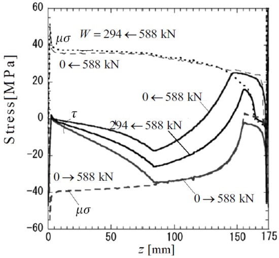
Figure 11.
Shear stress τ and frictional stress μσ along arbor surface contacted with sleeve when load is changed (μ = 0.5).
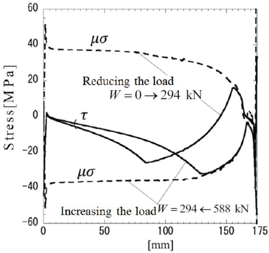
Figure 12.
Shear stress τ and frictional stress μσ along arbor surface contacted with sleeve when W = 0 → 294 kN and W = 294 ← 588 kN (μ = 0.5).
5. Quasi-Equilibrium Stress Zone with Residual Displacement Causing the Permanent Circumferential Slippage in Shrink-Fitted Sleeve Roll
In the previous sections, the permanent slippage was considered in the axial direction for back-up rolls in terms of residual displacement. In this section, another permanent slippage in the circumferential direction will be considered. Among rolling rolls used in steel industries, several sleeve-assembly-types are practically and successfully used. They have some advantages for back-up rolls having large trunk diameter exceeding 1000 mm and also for rolling rolls for large H-section steel [20,21]. However, sometimes circumferential slippage occurs in this shrink-fitted sleeve rolls. The slippage is seen in the opposite direction of rolling even though the resistance torque at the interface is larger than the motor torque. Few studies are available for this circumferential slippage in rolling roll, but a similar phenomenon is known as interface creep in ball bearing attracting attention [24,25,26] although no analytical studies can be found.
In the numerical simulation, the roll rotation is replaced by the load shifting on the fixed roll surface [22,23]. Here, two-dimensional rigid shaft and the elastic steel sleeve are assumed. Then, the interface slippage can be expressed from the interface displacement at the sleeve interface because of no displacement of the rigid shaft. In Section 4.2, it was shown that the residual deflection is caused by the relative slippage between the sleeve and the shaft. From the stress distributions along the shrink-fitted surface, the relative slippage condition was discussed in terms of the stress quasi-equilibrium region.
In this section, first, to confirm the residual displacement, the slippage region will be investigated. If the slippage region is confirmed, the residual displacement should be found in a similar way in Section 4.2. Therefore, by removing the loading the residual displacement will be discussed. Figure 13a shows the quasi-equilibrium stress region where slippage occurs as when the pair of loads applied at the position and . When the initial loads and are applied, the slippage occurs around and . As shown in Figure 13b, after removing the initial loads as , the slippage region becomes smaller. However, the quasi-equilibrium stress region where the slippage occurs still exists near the loaded position and . Figure 14 shows the displacement distributions under the initial load and after removing the initial load as . From Figure 14, it is confirmed that the displacement remains near the slippage region even after removing the load. The remaining displacement is regarded as the residual displacement.
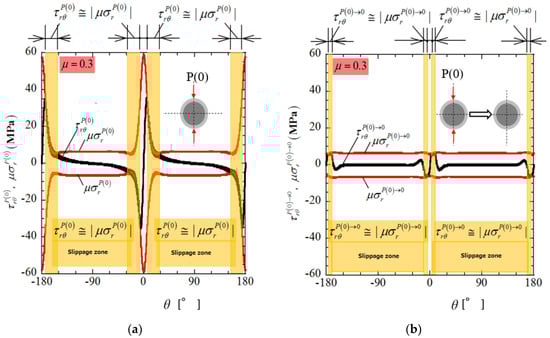
Figure 13.
Comparison of slippage zone under the initial loading and slippage zone after removing the initial loading → 0, (a) under the initial loading ; (b) after removing the initial loading .
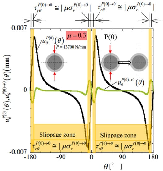
Figure 14.
Residual displacement after removing the initial load in comparison with displacement due to initial load.
When the roll is rotating under the initial loads, the residual displacement will be accumulated. Under the initial load without roll rotation, the average displacement is zero as shown in Figure 9. However, with increasing the roll rotation angle, the average displacement may increase and may cause interfacial circumferential slippage.
6. Conclusions
In this study, numerical simulation was performed to realize the residual deflection in sleeve constructed roll where the sleeve was assembled to the shaft by shrinkage fitting. The finite element method was carried out for and the following conclusions were obtained.
- (1)
- Residual deflection after removing the load W = 294 kN coincides with the previous experimental results within 15% error.
- (2)
- With increasing the friction coefficient μ, the residual deflection increases having a peak value around μ = 0.1–0.2, then decreases. The friction coefficient providing the peak varies depending on the magnitude of the load applied before removing the load.
- (3)
- (4)
- The same residual deflection can be obtained when the product of the quasi-equilibrium zone and the distance from this region to z = 0 is almost the same. Here, the quasi-equilibrium zone can be defined as the region where the shear force is balanced the friction as within 1 MPa difference.
- (5)
- The quasi-equilibrium stress zone and the residual displacement are strongly related to the residual deflection. The quasi-equilibrium stress zone can be seen in the circumferential direction between the sleeve and shaft may cause the circumferential interfacial slippage.
Author Contributions
N.-A.N. supervised the research; H.S. conducted the research; Y. Sano proposed and advised the research; Y.T. and Y. Shimoda. performed the FEM simulation.
Funding
This research received no external funding.
Conflicts of Interest
The authors declare no conflict of interest.
References
- Lindsey, E.G. Backup Rolls and their Contribution to Gage Variation. Iron Steel Engr. 1960, 37, 91. [Google Scholar]
- Hohage, R. Support Rollers for Cold Rolling Mills. Steel Iron 1939, 59, 1197–1204. [Google Scholar]
- Hori, K. Model Test on the Mechanism of the Residual Deflection of Built-up Type Back-up Rolls; Technical Papers (Part II) for the 70th Grand Lecture Meeting of The Iron and Steel Institute of Japan: Tokyo, Japan, October 1965; pp. 200–202. [Google Scholar]
- Trinks, W. Pressures and Roll-Flattening in Cold Rolling. Steel Plant 1937, 25, 617–619. [Google Scholar]
- Ohkomori, Y.; Sakae, C.; Murakami, Y. Analysis of Mode II Crack Growth Behavior in Spalling Failure of Backup Roll. J. Soc. Mat. Sci. 2001, 50, 249–254. [Google Scholar] [CrossRef]
- Shimoda, H.; Onodera, S.; Hori, K. Study on the Residual Deflection of Large Sleeved Back-Up Rolls: 1st Report, Mechanism of the Deflection. Trans. Jpn. Soc. Mech. Eng. 1966, 32, 1–7. [Google Scholar] [CrossRef]
- Shimoda, H.; Onodera, S.; Hori, K. Study on the Residual Deflection of Large Sleeved Back-Up Rolls: 3rd Report, Effect of Condition at Shrink Fitting Interface, Welding at Barrel Ends and Other Factors on the Deflection. Trans. Jpn. Soc. Mech. Eng. 1966, 32, 440–446. [Google Scholar] [CrossRef]
- Shimoda, H.; Onodera, S.; Hori, K. Study on the Residual Deflection of Large Sleeved Back-Up Rolls: 4th Report, Residual Stresses of Sleeved Rolls. Trans. Jpn. Soc. Mech. Eng. 1966, 32, 689–694. [Google Scholar] [CrossRef]
- Shimoda, H.; Onodera, S.; Hori, K. Study on the Residual Deflection of Large Sleeved Back up Rolls: 5th Report, Analysis on the Machanism of the Deflection and the Efficacy of the Counter-measure of the Residual Deflection about Actual Rolls. Trans. Jpn. Soc. Mech. Eng. 1967, 33, 11–18. [Google Scholar] [CrossRef]
- Gruner, H. Investigations on Machine-Induced Influences on the Uniformity of Cold-Rolled Strips. Steel Iron 1957, 77, 347–353. [Google Scholar]
- Kawai, M.; Kitsuki, K.; Nozaki, Y.; Takeuchi, H.; Miura, K. On the Bending Deflection of Model Rolls, Investigation of bending deflection on the built-up type back-up rolls for 4 high strip mills I. In Proceedings of the Preprints for the 66th Grand Lecture Meeting of The Iron and Steel Institute of Japan, Tokyo, Japan, 1 September 1963; pp. 1613–1615. [Google Scholar]
- Ookomori, Y.; Kitagawa, I.; Shinotsuka, K.; Miyamoto, R.; Yazaki, S. Study on Spalling of Hot Strip Mill Backup Roll. Tetsu-to-Hagané 1987, 73, 691–698. [Google Scholar] [CrossRef]
- Tsutsumi, S.; Hara, S.; Yoshi, S. The Residual Deflection of Sleeved Back-up Rolls. Tetsu-to-Hagané 1971, 57, 818–822. [Google Scholar] [CrossRef]
- Noda, N.N.; Sano, Y.; Wang, X.; Nakagawa, Y.; Guan, W.H.; Ono, K.; Hu, K. Residual Stress Simulation and Generation Mechanism for Hot Strip Composite Roll during the Quenching. J. Automot. Eng. 2015, 46, 831–837. [Google Scholar] [CrossRef]
- Sano, Y. Recent advances in rolling rolls. In Proceedings of the No. 148–149 Nishiyama Memorial Technology Course, Tokyo, Japan, 17 May 1993; pp. 193–226. [Google Scholar]
- Tanaka, T.; Kanzaki, M.; Terakado, R.; Tabe, H.; Kudo, K.; Goto, H. Survey on usage of back-up rolls: Roll and steel sheet investigation of continuous hot rolling mill II (thin plate processing/processing general, steel making processing). In Proceedings of the 74th Grand Lecture Meeting of The Iron and Steel Institute of Japan, Tokyo, Japan, 31 August 1967. [Google Scholar]
- Zhua, Z.; Sunb, D. Stress-Strain Analysis of Back-up Roll with Roll-Sleeve. Appl. Mech. Mater. 2012, 1, 139–142. [Google Scholar] [CrossRef]
- Dong, Y.; Wang, M.; Su, Y. Building the Mathmatical Model of Elastic Deformation for Rolls System by Four-High Mill Strip Rolling with a Composite Back-Up Roll. Adv. Mater. Res. 2012, 413, 320–325. [Google Scholar] [CrossRef]
- Frolish, M.F.; Beynon, J.H. Design criteria for rolling contact fatigue resistance in back-up rolls. Ironmaking Steelmaking 2004, 31, 300–304. [Google Scholar] [CrossRef]
- Takigawa, H.; Hashimoto, K.; Konno, G.; Uchida, S. Development of forged high-speed-steel roll for shaped steel. In Proceedings of the Current Advances in Materials and Processes: Report of the ISIJ Meeting, Tokyo, Japan, September 2003; pp. 1150–1153. [Google Scholar]
- Irie, T.; Takaki, K.; Tsutsunaga, I.; Sano, Y. Steel strip and section steel and thick rolling, processing. In Proceedings of the Japan Iron and Steel Institute 97th (Spring) lecture meeting, Tokyo, Japan, 7 March 1979. [Google Scholar]
- Noda, N.-A.; Suryadi, D.; Kumasaki, S.; Sano, Y.; Takase, Y. Failure Analysis for Coming out of Shaft from Shrink-Fitted Ceramics Sleeve. Eng. Fail. Anal. 2015, 57, 219–235. [Google Scholar] [CrossRef]
- Noda, N.-A.; Xu, Y.; Suryadi, D.; Sano, Y.; Takase, Y. Coming Out Mechanism of Steel Shaft from Ceramic Sleeve. J. ISIJ Int. 2016, 56, 303–310. [Google Scholar] [CrossRef]
- Soda, N. Bearing; Iwanami Shoten: Tokyo, Japan, 1964; pp. 196–203. [Google Scholar]
- Niwa, T. A Creep Mechanism of Rolling Bearings. NTN Tech. Review 2013, 81, 100–103. [Google Scholar]
- Murata, J.; Onizuka, T. Generation Mechanism of Inner Ring Creep. J. Koyo Eng. 2004, 166, 41–47. [Google Scholar]
© 2018 by the authors. Licensee MDPI, Basel, Switzerland. This article is an open access article distributed under the terms and conditions of the Creative Commons Attribution (CC BY) license (http://creativecommons.org/licenses/by/4.0/).