Abstract
Brazing of titanium provides a joining technique suitable for the fabrication of highly-loaded aerospace components, but it still poses numerous challenges, such as the formation of brittle intermetallic interphases. This study of the interphase formation in brazed joints consisting of different titanium alloys (Ti-CP2, Ti-CP4, Ti-6Al-4V, Ti-6Al-2Mo-4Zr-2Sn) and Ag28Cu shows that complex reactions lead to the formation of various intermetallic phases including a Ti2Cu-TiCu boundary zone. The compositions of the titanium alloys influenced the particular microstructures, which have been characterized with various methods including synchrotron X-ray microtomography. Tensile tests evidence high ultimate tensile strengths that are, importantly, not directly limited by the strength of the brazing alloy. The strength of the Ti2Cu-TiCu phase boundary is significantly increased by the alloying elements in Ti-6Al-4V and Ti-6Al-2Mo-4Zr-2Sn and the crack paths change from boundary failure to transcrystalline fracture through TiCu as well as Ag-rich regions. Cu diffusion into the titanium substrate, leading to a coarse grained β-phase that transforms eutectoidally into a lamellar α-Ti + Ti2Cu structure during cooling, occurred in all systems except Ti-6Al-2Mo-4Zr-2Sn where Mo stabilized a fine grained microstructure and enabled the formation of a columnar TiCu structure.
1. Introduction
Brazing is currently being investigated as a joining technique for manufacturing aerospace components made of Ti alloys [1,2]. This technique is used for joining similar or, importantly, dissimilar [3,4] metallic parts by melting a brazing solder with a melting point lower than that of the base materials. Various solders are usually applied for Ti and Ti alloys, in particular Al-based (e.g., Al-1Mn), Pd-based (e.g., Pd-60Cu-10Co), Ti based (e.g., Ti-15Cu-15Ni) and near-eutectic Ag-Cu-based alloys [5,6]. The latter are particularly attractive owing to their low melting point, suitable wetting behavior and relatively high strength [5]. However, complex interfacial reactions take place as it has been reported in detail by several authors [3,7,8,9,10]:
- (1)
- Dissolution of Ti and alloying elements in the solder alloy
- (2)
- Diffusion of Cu from the solder into the base material
- (3)
- Formation of Ti-Cu-rich intermetallic phases
- (4)
- Depletion of Cu in the melt, especially in the vicinity of the base material
- (5)
- Isothermal solidification of Ag as a consequence of Cu depletion
- (6)
- Precipitation of intermetallic phases from the residual melt
- (7)
- Eutectoid β-Ti → α-Ti + Ti2Cu reaction in the Cu-enriched diffusion zone
The technological advantages of brazing Ti-based parts can be underlined on the basis of an example of an aerospace application, in which complex titanium parts are joined using a Ag-Cu solder for manufacturing a new rotor concept for aero-engines [1]. Here, three titanium-based discs are joined together in one brazing step. The benefit of this approach is that individual compressor discs can be machined to final shape, allowing for a higher design freedom before joining to form a monolithic structure (machining of the complete rotor is not feasible owing to the complex geometry of the part). Furthermore, the comparatively low melting point (below the β-transus temperature of Ti) of the Ag-Cu solder does not severely degrade the heat treatment of the individual discs.
The Ti-Ag-Cu system has been previously investigated in connection with the development of cost-efficient metal matrix composites [11]. For this purpose, SiC fibres were coated with pure Ti or Ti-6Al-2Sn-4Zr-2Mo (wt. %) and consolidated through infiltration of an eutectic Ag-Cu alloy [12]. In a previous study [11] we found that the composition of the titanium matrix significantly affected the formation of the intermetallic structure in the transition zone, which in consequence resulted in different fracture modes. Cracks formed mainly at the intermetallic phase boundaries in the Ti/AgCu system during tensile deformation, whereas cracks particularly along the columnar intermetallic structure of the intermetallic phase TiCu were observed in Ti6242/AgCu. Thus, the present work aims at elucidating the effects of the composition and microstructure of titanium alloys on the formation of interfacial reactions, and the resulting strength and fracture behavior of joints brazed using a eutectic Ag28Cu filler alloy.
2. Materials and Methods
Four Ti alloys were chosen for the investigations: Commercially pure Ti, ASTM grade 2 (Ti-CP2), commercially pure Ti grade 4 (Ti-CP4) with a higher amount of impurities (especially iron and oxygen), Ti-6Al-4V (Ti64) and Ti-6Al-2Sn-4Zr-2Mo (Ti6242). The maximum concentrations of alloying elements are summarized in Table 1.

Table 1.
Composition of titanium alloys (maximum values according to specification in wt. % [13] (bal: balance).
The eutectic alloy Ag28Cu (28 wt. % Cu) purchased from UMICORETM (Brussels, Belgium) with a melting temperature of 780 °C was used as brazing material.
In the brazing experiments, two cylindrical parts (Ø = 11.2 mm, length = 33 mm) of the same Ti alloy were fixed together with a 80-µm-thick Ag28Cu foil in between, heated in a high-vacuum (<10−5 mbar) furnace up to ~820 °C, held at this temperature for 10 min, and slowly cooled with a cooling rate less than 1 K/s.
Tensile test samples with a total length of 60 mm, a diameter Ø = 3.5 mm and a gauge length of 10 mm were machined by turning the brazed rods. Six marking stripes for a laser extensometer were glued within the gauge length of the samples. The strength of the samples was determined using a universal electro-mechanical testing machine (Instron POZ1960, Instron, Darmstadt, Germany), while the elongation was measured with a laser extensometer (P130, Fiedler Optoelektronik, Lützen, Germany).
Longitudinal sections as well as fracture surfaces were investigated using a Zeiss Ultra 55 scanning electron microscope (SEM, Zeiss, Oberkochen, Germany) equipped with energy dispersive X-ray spectroscopy (EDS).
The fracture surfaces were investigated with a confocal laser scanning microscope ZEISS LSM 700 with PILine© workstation (Oberkochen, Gemany). The height profiles were analyzed three-dimensionally according to ISO 25178 using ConfoMap©—3D Advanced Surface Texture module (Zeiss, Oberkochen, Germany).
X-ray diffraction (XRD) of the fracture surfaces was carried out with a Bruker D8 discover with Cu Kα radiation and a beam diameter of ~1 mm.
Synchrotron X-ray microtomography (SXCT) investigations of the brazed regions were carried out at the beamline ID19 of the European Synchrotron Radiation Facility (ESRF) in Grenoble. Samples of 0.9 × 1.1 × 8 mm³ (x, y, z respectively) were prepared by wire cutting with the joint being oriented in the x,z-plane. The tomographic scans were carried out at energy of 35 keV. A pco.edge detector (2560 × 2160 pixels: 845 × 713 µm²) was used to obtain a voxel size of (0.33 µm)3. 8000 projections were acquired at 0.15 frames/s operating in half acquisition mode to double the field of view of the detector.
3. Results
We distinguish between three different regions of the brazed samples for the description and interpretation of the material systems: The chemically unaffected base Ti alloy, a transition zone consisting of chemically modified base alloy as well as intermetallic phases, and the Ag-rich region.
The intermetallic phases are designated hereafter based on the binary system Ti-Cu, although the phases can contain significant amounts of Ag (see e.g., phase diagrams of Ti-Cu-Ag [14]) and other constituents of the Ti alloys.
3.1. Microstructure of the Brazing Joints
A comparison of brazing joint cross sections of the considered material systems (Figure 1) shows similarities as well as clear differences in the interface formation: Cu from the brazing alloy participates in the interfacial reactions to form different consecutive intermetallic layers consisting of Ti-Cu-based phases.
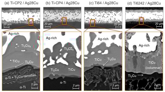
Figure 1.
SEM micrographs of the brazing region for all investigated compounds: Ti-CP2 (a), Ti-CP4 (b), Ti64 (c) and Ti6242 (d). While alloying elements participate in the interface reactions, only phase designations according to the Ti-Cu phase diagram are presented here for legibility. Typical results of the EDS analysis are summarized in Table 2.
The main intermetallic phases observed here are modifications of Ti2Cu, TiCu and Ti3Cu4 according to EDS (See Table 2), which is widely consistent with the layer sequence reported by Andrieux et al. [9] for Ag28Cu unsaturated with Ti. In our study, Ti2Cu3 was not observed as it can only be expected for higher temperatures or longer reaction times [8]. The thickness of the layers is not entirely uniform, with an average of approx. 10 µm for TiCu and 0.5 µm for Ti2Cu, whereas no continuous Ti3Cu4 layer is formed but regions of up to 7 µm width are recognized.
Table 2.
Results of EDS analysis of intermetallic phases in the transition zone (Figure 1) (at. %).
There is a ~7 µm thick biphasic microstructure between the chemically unaffected base alloy Ti-CP2 and the Ti2Cu layer (Figure 1a), consisting of α-Ti with fine Ti2Cu lamellae that formed during cooling from Cu-rich β-Ti [10] region by means of an eutectoid reaction at ~800 °C [15,16].
The transition zone in the case of Ti-CP4/Ag28Cu (Figure 1b) appears similar to Ti-CP2/Ag28Cu and the same sequence of intermetallic layers (Ti2Cu, TiCu and Ti3Cu4) with analogous chemical compositions (based on EDS, Table 2) was found. However, there is one remarkable difference: Ti-CP4 appears less affected by Cu diffusion into the base material since the eutectoid zone made up of α-Ti + Ti2Cu is less pronounced and has a completely different structure that will be considered in detail later.
Also for Ti64/Ag28Cu (Figure 1c), a similar configuration of the intermetallic layers is found. Again TiCu and Ti2Cu are observed but the chemical compositions indicate the presence of Al (Table 2). Also Ti3Cu4 is detected (not visible in Figure 1), which does not contain a large amount of Al. Moreover, a second Cu-rich phase with a considerable amount of Al was detected with EDS (~65 at. % Cu, ~25 at. % Ti, ~8 at. % Al, 2 at. % Ag, Table 2). Unlike the other intermetallic phases, its crystal structure could not be clarified in our study, but it should correspond to the phase TiCu2Al [17,18]. The fine lamellar eutectoid reaction zone contains V and Cu, although a local discrimination of both elements is not possible by EDS.
In contrast to the previous systems, Ti6242/Ag28Cu shows a comparatively thick columnar TiCu-layer. The EDS analysis reveals similar chemical compositions as the Al-enriched phases in Ti64/Ag28Cu with the addition of some Zr. The phases TiCu and Ti2Cu contain Ag, Zr and Al (Table 2) and there is an accumulation of Al and also Zr close to the Ag-rich phase (Figure 2), probably also due to the formation of TiCu2Al.
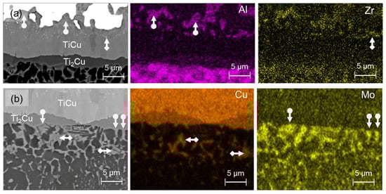
Figure 2.
EDS mapping of the cross section of the brazing joint Ti6242/Ag28Cu. (a) An Al-rich phase (marked with arrows, probably TiCu2Al) which also contains Zr can be recognized clearly. (b) Enrichment with the elements Cu and Mo in separate areas (marked with arrows) can be seen below the Ti2Cu layer.
This phase allows for the incorporation of more Al than Ti2Cu, TiCu, and Ti3Cu4, according to the phase diagram of the system Al-Cu-Ti [18]. No Ti3Cu4 was detected by EDS point measurements, and the mapping (Figure 2) also indicates its presence as in the case of Ti64/Ag28Cu.
3.2. Characterization of Joints by Synchrotron X-Ray Microtomography (SXCT)
The distribution and morphology of the intermetallic phases were examined three dimensionally by SXCT. A 3D visualization of the joint area of brazed Ti-CP2 is presented in Figure 3 with an unsegmented tomographic reconstruction showing the brazing region between the two Ti-CP2 parts is given as a grey-scale cuboid. The main microstructural components in the brazed region are presented separately in the front: The intermetallic transition zone (grey), the Ag-rich region (white) and intermetallic particles inside the Ag-rich region (red).
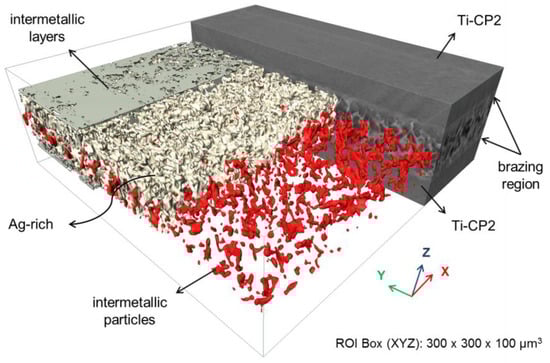
Figure 3.
3D distribution of microstructural constituents in the brazing region of the Ti-CP2/Ag28Cu system obtained by SXCT. The cuboid (grey-scale) in the back shows a brazing region between two Ti-CP2 parts while in the front the constituents are presented separately: Intermetallic layers, Ag-rich region and intermetallic particles inside the Ag-rich region.
The intermetallic particles in the Ag-rich volume have different morphologies, sizes and volume fractions depending on the base Ti alloy, despite the fact that the solidification and cooling conditions during brazing were the same (Figure 4).
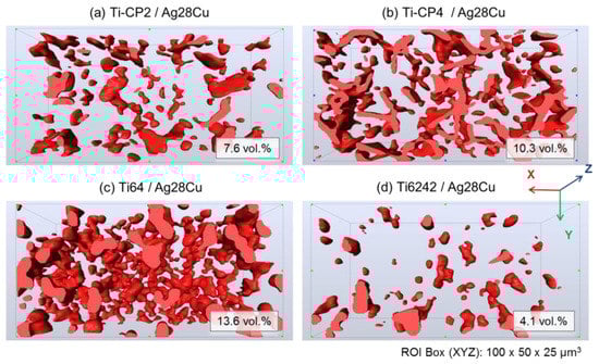
Figure 4.
Comparative 3D visualizations of the intermetallic particles embedded in the Ag-rich region (horizontal cuts of the isometric top view): (a) Ti-CP2/Ag28Cu, (b) Ti-CP4/Ag28Cu, (c) Ti64/Ag28Cu, (d) Ti6242/Ag28Cu.The Ag-rich region is transparent. The total volume fractions specified here were determined from volumes of 300 × 300 × 50 µm³.
The Ti-CP2/Ag28Cu system exhibits small randomly arranged platelet-like particles ≤5.000 µm3 and a fraction of ~8 vol. % in the investigated volume (Figure 4a). Similar platelet-like intermetallic particles, although partially interconnected, are found in Ti-CP4/Ag28Cu (Figure 4b). Here, the total volume fraction is ~10 vol. %. Irregular particles amounting to ~14 vol. % are detected in Ti64/Ag28Cu (Figure 4c), whereas for Ti6242/Ag28Cu ~4 vol. % of small round intermetallic particles are found. According to EDS the particles predominantly consist of Ti3Cu4 in the case of the commercially pure grades Ti-CP2 and Ti-CP4, whereas in the Al-containing systems the Al-rich phase (TiCu2Al) was also detected (see Section 3.1).
3.3. Tensile Tests
Tensile tests carried out on brazed specimen of the different systems (Figure 5) showed stress-strain curves that at large indicate a brittle joint behavior for the α + β alloy Ti64 and the near-α alloy Ti6242.
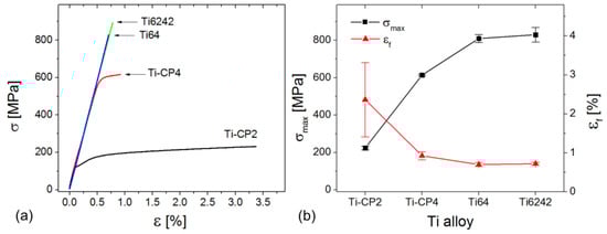
Figure 5.
(a) Typical stress-strain curves of the joints, (b) tensile strength σmax and elongation at fracture εf of the joints. An average from three test specimens is presented.
Some ductility was observed in Ti-CP4/Ag28Cu and more markedly for Ti-CP2/Ag28Cu. The tensile strengths differ considerably between the material systems, and the data in Table 3 demonstrates that there is a correlation between the strengths of the titanium alloys and the strengths of joints.
Table 3.
Comparison of strengths of brazing joints and strength of base material [19,20].
3.4. Fractography
SEM fractographs of the halves of the fractured samples without the Ag-rich region (Figure 6) indicate that the crack path depends strongly on the microstructure of the interface region. The fracture surface of Ti-CP2/Ag28Cu exhibits a homogeneous undulating cellular morphology (Figure 6a). A similar surface morphology can be found for Ti-CP4/Ag28Cu, although a few small sharp-edged particles can be observed (Figure 6b). In contrast, the fracture surface of the Ti64/Ag28Cu joint is covered with fractured plate-like flakes (Figure 6c). Finally, the fracture surface of Ti6242/Ag28Cu comprises deep crater-like regions in which parts of the reaction zone were pulled out during tensile testing (Figure 6d). The color scaled images on the right side of each subfigure show the height profile measured by confocal laser scanning microscopy. The surface of Ti-CP2/Ag28Cu appears relatively homogeneous (maximum corrugation is about 10 µm), whereas the fracture surface of the Ti-CP4/Ag28Cu and especially Ti64/Ag28Cu joints present scarce regions with significantly more elevated areas, which can be explained by the observed fractured platelet-like flakes mentioned above. The Ti6242/Ag28Cu joint exhibits plateaus with different heights that can be traced back to the pulled out regions observed by SEM.
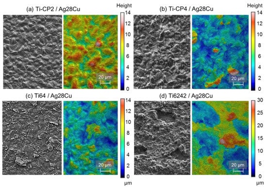
Figure 6.
Fracture surfaces of the samples halves without the Ag-rich regions (excluding joint): Fractographs obtained by SEM (left image of each subfigure) and height profiles measured by confocal laser scanning microscopy (right image of each subfigure).
The fracture surfaces were also characterized by XRD (Figure 7). The results for the surfaces of the sample halves with and without the Ag-rich region of the Ti-CP2/Ag28Cu system are shown in Figure 7a. The near-surface area excluding the joint consists mainly of Ti2Cu and α-Ti, whereas the half including the joint contains mainly TiCu and Ag, indicating that the fracture path took course predominantly at the phase boundary between Ti2Cu and TiCu (see also Figure 1a). A comparison of the diffractograms of all investigated brazing systems for the sample halves excluding the joint shows similar results for the commercially pure grades (Ti-CP2, Ti-CP4), while TiCu is additionally observed for Ti64 and even more TiCu and Ag for Ti6242 (Figure 7b).
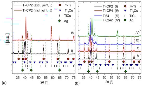
Figure 7.
X-ray diffraction analysis: (a) Comparison of both fractured sample halves (excluding and including joint) for the Ti-CP2/Ag28Cu joint with the main identified phases. (b) Diffractograms of all investigated joints for the sample halves excluding the joint.
Based on these results the fracture surfaces were analyzed using EDS. The phases identified are presented in Figure 8 with the corresponding fracture surface region. The results confirm that the fracture path in the Ti-CP2/Ag28Cu system proceeds almost exclusively along the TiCu/Ti2Cu phase boundary. Only in very few cases transcrystalline fracture through TiCu crystals could be observed (Figure 6a and Figure 8a, here, additionally, the half of the sample including the Ag-rich part of the joint is depicted). In the Ti-CP4/Ag28Cu system (Figure 6b and Figure 8b), slightly more TiCu fragments and also some Ag-rich areas could be observed, while, in agreement with XRD results, the amount of TiCu at the surface is much higher in Ti64/Ag28Cu (Figure 6c and Figure 8c). Plateaus covered with dimples indicating local plastic deformation of the Ag-rich phase were observed in Ti6242/Ag28Cu (Figure 6d and Figure 8d), explaining the Ag detected in the XRD measurement (Figure 7b).
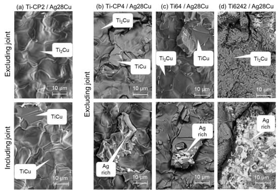
Figure 8.
SEM+EDS investigation of the fracture surfaces of both halves of the Ti-CP2/Ag28Cu specimen, i.e., excluding the joint at the top and including the joint at the bottom (a), fracture surfaces of the parts excluding the joint for Ti-CP4/Ag28Cu (b), Ti64/Ag28Cu (c) and Ti6242/Ag28Cu (d). All indicated phases were identified by EDS at the pointed regions.
Longitudinal sections of the near-surface region of the fractured tensile specimen provide complementary information (Figure 9—load direction was vertical). A predominantly intact Ti2Cu layer with a marginal amount of TiCu fragments was observed in Ti-CP2/Ag28Cu (Figure 9a) above the approx. 15-µm-thick eutectoid α-Ti/Ti2Cu region. TiCu fragments were found on the surface of Ti-CP4/Ag28Cu (Figure 9, bottom), while the eutectoidically transformed lamellar region below the Ti2Cu layer has a coarser but much thinner structure (Figure 9b top). Additionally, EDS revealed the Fe-rich β-Ti phase besides Ti2Cu. Even more TiCu fragments and a large number of secondary cracks can be observed in case of Ti64/Ag28Cu (Figure 9c), while the eutectoid α-Ti + Ti2Cu zone below the Ti2Cu layer is approx. 5 µm in width. A completely different damage behavior was found for Ti6242/Ag28Cu (Figure 9d): The crack propagates frequently across the thick columnar TiCu layer, partially along the TiCu columns with many secondary cracks. A eutectoid reaction zone below the Ti2Cu layer cannot unambiguously be identified as the Cu-enriched area gradually merges with the globular α + β microstructure.
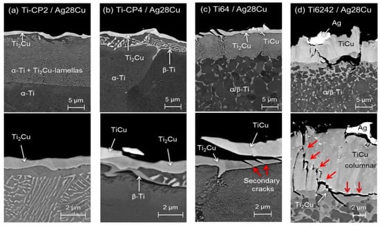
Figure 9.
SEM-Micrographs of longitudinal sections of the fractured tensile specimen excluding the joints at low (top row) and high (bottom row) magnification.
4. Discussion
4.1. Brazing Reaction Products
The investigated joints show the formation of intermetallic layers at the interface between the Ti substrate and the Ag-rich region for all investigated Ti alloys (Figure 1). Moreover, the reaction products extend well into the Ag-rich region and intermetallic particles with different morphologies are formed (Figure 4), i.e., predominantly Ti3Cu4 for Ti-CP2 and Ti-CP4, whereas TiCu2Al also was found for Ti64 and Ti6242. Al has a considerable solubility in Ag and Cu [6] and dissolves easily in the melt. During solid state transformations and solidification it is incorporated in the intermetallic Ti-Cu phases (Table 2).
Moreover, Zr was detected in all Ti-Cu intermetallic phases of the Ti6242-Ag28Cu joint. It has previously been shown that TiCu can incorporate Zr [21,22], while there exists a continuous solid solution (Ti,Zr)2Cu intermetallic also designated γ-phase [22]. Nevertheless, the highest amount of Zr was detected in the Al-enriched phase (Figure 2 and Table 2), indicating that TiCu2Al can also incorporate a significant amount of Zr.
The presence of only small amounts of Mo is a consequence of the low solubility of this element in the Ti-Cu phases [23]. No eutectoid reaction zone consisting of α-Ti + Ti2Cu could be found in the Ti6242/Ag28Cu joint, contrary to the Ti64/Ag28Cu and the Ti-CP2/CP4 systems, while there are Mo-rich grains (β-Ti) besides Cu-rich areas (probably Ti2Cu) mainly at the grain boundaries of α-Ti (Figure 2), indicating that two separate β phases may form during brazing, namely one Mo-enriched and one Cu-enriched.
The absence of the lamellar structure from the eutectoid reaction in the Ti6242/Ag28Cu joints (in contrast to the Ti64/Ag28Cu system, Figure 9c) implies that no homogeneous, coarse grained β-Ti layer is formed during the brazing process, presumably owing to the lower diffusivity of Mo [24] and its higher β stabilization effect [25] as compared to that of V. As a result the Mo-rich regions beyond the growing intermetallic phases remain stable at 820 °C and Cu diffuses into the former α-regions to form β. During cooling β transforms eutectoidally into α-Ti + Ti2Cu and thus different regions with Mo-rich β-Ti, Ti2Cu and α-Ti are obtained. Moreover, during brazing of Ti6242/Ag28Cu the microstructure in the Cu diffusion zone remains fine grained and a fine columnar TiCu structure is formed (Figure 1 and Figure 9).
4.2. Strength and Failure Mechanisms of the Joints
The crack path in the tensile specimen is found to depend strongly on the microstructure of interface region, which is schematically depicted in Figure 10 for all joints. Fracture takes place predominantly at the interface between Ti2Cu and TiCu for Ti-CP2 (Figure 10a), revealing the structural weakness of this boundary. The contribution of transgranular fracture through TiCu increases for Ti-CP4 (Figure 10b) and particularly Ti64 (Figure 10c). In the case of Ti6242 (Figure 10d) the phase boundary between Ti2Cu and TiCu is more stable and, therefore, the fracture path deflects from the Ti2Cu-TiCu boundary into the Ag-rich phase, which leads to the plateaus with dimples observed in this region (Figure 6d). This may be because the Ag-rich area has a lower strength in this system due to the lower volume fraction of intermetallic particles (Figure 4d).
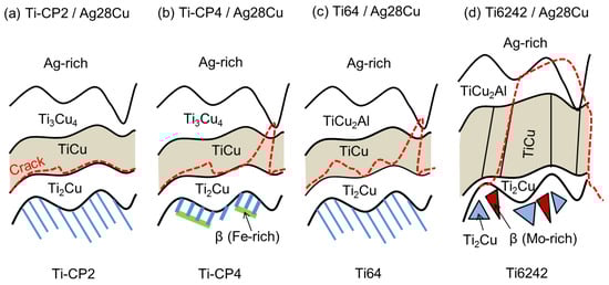
Figure 10.
Schematic representation of the different failure modes found for the different brazing systems: Ti-CP2/Ag28Cu (a), Ti-CP4/Ag28Cu (b), Ti64/Ag28Cu (c), Ti6242/Ag28Cu (d). The crack paths are indicated by dashed red lines.
The microstructural analysis (see Section 3) indicates that the weakest links of the brazed joints are the transition zones, i.e., the intermetallic phases, which might seem surprising, since according to the technical data sheet [26] the strength of the Ag28Cu alloy used for brazing shows only a low strength of ≤390 MPa. This can be attributed to the composite-like structure of these regions owing to the formation of intermetallic phases in Ag-rich matrix during brazing (Figure 4).
The joints with commercially pure grades fail under loads close to the yield strength of the base alloys (Table 3). Thus, the UTS is much higher in the case of Ti-CP4/Ag28Cu, although the results of the microstructural and fractographical analyses of both grades are similar. The only obvious microstructural difference between the joints of both grades is the extended lamellar α-Ti + Ti2Cu zone within the bulk Ti-CP2 below the Ti2Cu layer (Figure 9a), indicating that the diffusion of Cu into Ti is restricted by the presence of higher amounts of O and, especially, Fe in Ti-CP4 (Table 1). The SEM investigations revealed the presence of Fe-rich grains (β-Ti), which seem to have formed a boundary for diffusion of Cu since these grains are predominantly found as a layer below the eutectoid reaction zone (Figure 9b). However, this microstructural difference provides no direct explanation for the different strength. We hypothesize that compositional differences (Fe, O) at the phase boundaries may instead be responsible for the behavior, which has to be investigated on the submicrometer scale, e.g., by atom probe tomography and transmission electron microscopy.
In contrast to the CP titanium grades, the joints of Ti64 and Ti642 show much higher strengths and fail at stresses close below the yield strength of the base alloys. In these systems the grain size of the base metal is fine grained and biphasic. The reaction zones of the Ti64/Ag28Cu joints resemble extensively those of the commercially pure grades whereas those of Ti6242/Ag28Cu are very dissimilar as outlined in Section 3.1.
In spite of the structural similarity of CP2-Ti/Ag28Cu, CP4-Ti/Ag28Cu and Ti64/Ag28Cu joining zones, the strengths differ significantly, whereas the remarkable structural discrepancies between Ti64/Ag28Cu and Ti6242/Ag28Cu are not mirrored by strong strength differences. Therefore, the strength of the interfacial phase boundary Ti-Ti2Cu is considered to be essential for the performance of the brazed joints of Ti alloys. The considerable strengths differences are believed to be related to the alloying elements of the titanium base materials.
5. Conclusions
Brazing of titanium alloys has been studied in order to develop new insights into the formation of joints’ interphase regions, their microstructure and mechanical behavior under tensile loads.
For Ti-CP2 and to a large extent Ti-CP4, the ultimate tensile strength of the joints is mainly determined by the interface boundary strength between TiCu and Ti2Cu formed during brazing. Importantly, it is not governed by the strength of the base titanium alloy or the Ag-rich phase of the brazing material, despite the latter having a low strength. Very likely as a consequence of higher amounts of the alloying elements in Ti-CP4, particularly β-stabilizing Fe, the strength of the Ti2Cu-TiCu phase boundary is significantly increased and transcrystalline fracture through TiCu grains is more pronounced. In Ti64/Ag28Cu joints, very high UTS are associated with considerable transcrystalline fracture through TiCu. Finally, for Ti6242 the phase boundary strength in the Ti2Cu-TiCu zone is even higher, so that the fracture path deflects frequently through TiCu and the ductile Ag-rich phase of the joint.
The differences in the failure mechanism are thus linked to the structure of the intermetallic reaction zone in the joints’ interfaces, which is affected by the alloying elements. The most striking microstructural observation, i.e., the formation of fine grained columnar TiCu in Ti6242/Ag28Cu, is attributed to the stabilization by Mo during brazing in the Cu diffusion zone. For the other systems, Cu diffusion led to formation of a coarse grained β-phase, ahead of the growing intermetallic reaction zone, which transformed eutectoidally to α-Ti + Ti2Cu upon cooling.
The results of this study demonstrate that besides the already explored approaches, i.e., modification of the brazing solders (e.g., by Sn or In) and application of interlayers (e.g., with Ag or Pd), the composition of the base material can play a remarkable role—an issue that seems not adequately considered so far.
Author Contributions
J.G. and G.R. conceived and designed the project. G.K. performed and evaluated the synchrotron experiments. J.G. and G.K. performed all other experiments and microstructural analysis and analyzed the data. J.G., G.K., J.H. and G.R. contributed to the interpretation and discussion of the data and the writing of the paper.
Funding
We thank the German Research Foundation (Deutsche Forschungsgesellschaft, DFG) for financially supporting the project (RE 3596/1-3).
Acknowledgments
We thank E. Boller for her assistance in carrying out the synchrotron measurements at ESRF. T. Merzouk is gratefully acknowledged for his support and recommendations in sample preparation by brazing. E. Dietrich is thanked for his support by performing the tensile testing.
Conflicts of Interest
The authors declare no conflict of interest.
References
- Kocian, F.; Ebel, P.-B.; Drees, B.; Schulze, K.; Hausmann, J.; Voggenreiter, H. Hybrid structures in aero engines. CEAS Aeronaut. J. 2015, 6, 217–228. [Google Scholar] [CrossRef]
- Sandin, T. What´s happening with aerospace brazing. Weld. J. 2013, 92, 56–58. [Google Scholar]
- Laik, A.; Shirzadi, A.A.; Sharma, G.; Tewari, R.; Jayakumar, T.; Dey, G.K. Microstructure and Interfacial Reactions During Vacuum Brazing of Stainless Steel to Titanium Using Ag-28 pct Cu Alloy. Metall. Mater. Trans. A 2015, 46, 771–782. [Google Scholar] [CrossRef]
- Lee, J.G.; Lee, M.-K. Microstructure and mechanical behavior of a titanium-to-stainless steel dissimilar joint brazed with Ag-Cu alloy filler and an Ag interlayer. Mater. Charact. 2017, 129, 98–103. [Google Scholar] [CrossRef]
- Shapiro, A.; Rabinkin, A. State of the Art of Titanium-based Brazing Filler Metals. Weld. J. 2003, 82, 36–43. [Google Scholar]
- Raghavan, V. Ag-Al-Cu (Silver-Aluminum-Copper). J. Phase Equilib. 2008, 29, 256–258. [Google Scholar] [CrossRef]
- Shiue, R.K.; Wu, S.K.; Chan, C.H. The interfacial reactions of infrared brazing Cu and Ti with two silver-based braze alloys. J. Alloys Compd. 2004, 372, 148–157. [Google Scholar] [CrossRef]
- Andrieux, J.; Dezellus, O.; Bosselet, F.; Sacerdote-Peronnet, M.; Sigala, C.; Chiriac, R.; Viala, J.C. Details on the Formation of Ti2Cu3 in the Ag-Cu-Ti System in the Temperature Range 790 to 860 °C. J. Phase Equilib. Diffus. 2008, 29, 156–162. [Google Scholar] [CrossRef]
- Andrieux, J.; Dezellus, O.; Bosselet, F.; Viala, J. Low-Temperature Interface Reaction Between Titanium and the Eutectic Silver-Copper Brazing Alloy. J. Phase Equilib. Diffus. 2009, 30, 40–45. [Google Scholar] [CrossRef]
- Laik, A.; Shirzadi, A.A.; Tewari, R.; Kumar, A.; Jayakumar, T.; Dey, G.K. Microstructure and Interfacial Reactions During Active Metal Brazing of Stainless Steel to Titanium. Metall. Mater. Trans. A 2013, 44, 2212–2225. [Google Scholar] [CrossRef]
- Gussone, J.; Reinhard, C.; Kasperovich, G.; Gherekhloo, H.; Merzouk, T.; Hausmann, J. In-situ investigation of microcrack formation and strains in Ag–Cu-based multi-metal matrix composites analysed by synchrotron radiation. Mater. Sci. Eng. A 2014, 612, 102–114. [Google Scholar] [CrossRef]
- Leyens, C.; Hausmann, J.; Kumpfert, J. Continuous Fiber Reinforced Titanium Matrix Composites: Fabrication, Properties, and Applications. Adv. Eng. Mater. 2003, 5, 399–410. [Google Scholar] [CrossRef]
- Donachie, M.J. Titanium: A Technical Guide, 2nd ed.; ASM International: Materials Park, OH, USA, 2000; pp. 1–381. [Google Scholar]
- Kubaschewski, O. Ag-Cu-Ti (Silver-Copper-Titanium). In Ternary Alloy Systems. Non-Ferrous Metal Systems. Part 3: Selected Soldering and Brazing Systems; Effenberg, G., Ilyenko, S., Eds.; Springer: Berlin, Germany, 2007; Volume 11, pp. 63–74. [Google Scholar]
- Murray, J.L. The Cu−Ti (Copper-Titanium) system. Bull. Alloy Phase Diagr. 1983, 4, 81–95. [Google Scholar] [CrossRef]
- Okamoto, H. Cu-Ti (Copper-Titanium). J. Phase Equilib. 2002, 23, 549–550. [Google Scholar] [CrossRef]
- Liu, X.J.; Wang, C.P.; Ohnuma, I.; Kainuma, R.; Ishida, K. Phase equilibria and phase transformation of the body-centered cubic phase in the Cu-rich portion of the Cu–Ti–Al system. J. Mater. Res. 2008, 23, 2674–2684. [Google Scholar] [CrossRef]
- Schmid-Fetzer, R. Al-Cu-Ti (Aluminium-Copper-Titanium). In Ternary Alloy Systems. Light Metal Systems. Part 2: Selected Systems from Al-Cu-Fe to Al-Fe-Ti; Effenberg, G., Ilyenko, S., Eds.; Springer: Berlin, Germany, 2005; Volume 11, pp. 156–173. [Google Scholar]
- Boyer, R.; Welsch, G.; Collings, E.W. Materials Properties Handbook: Titanium Alloys; ASM International: Materials Park, OH, USA, 1994; pp. 1–1169. [Google Scholar]
- Leyens, C.; Peters, M. Titanium and Titanium Alloys: Fundamentals and Applications; Wiley-VCH: Weinheim, Germany, 2003. [Google Scholar]
- Turchanin, M.A.; Velikanova, T.Y.; Agraval, P.G.; Abdulov, A.R.; Dreval’, L.A. Thermodynamic assessment of the Cu-Ti-Zr system. III. Cu-Ti-Zr system. Powder Metall. Met. Ceram. 2008, 47, 586–606. [Google Scholar] [CrossRef]
- Storchak-Fedyuk, A.M.; Artyukh, L.V.; Grytsiv, A.V.; Agraval, P.G.; Turchanin, M.A.; Velikanova, T.Y. Phase Equilibria in the Cu–Ti–Zr System at 750°C. II. The Isothermal Section with Copper Content from 50 to 100 at.%. Powder Metall. Met. Ceram. 2017, 56, 220–230. [Google Scholar] [CrossRef]
- Wang, C.P.; Liu, H.; Yang, M.J.; Jiang, H.X.; Zhang, H.Y.; Liu, X.J. Experimental Investigation of Phase Equilibria in the Cu–Mo–Ti Ternary System. J. Phase Equilib. 2018, 39, 35–43. [Google Scholar] [CrossRef]
- Zhu, L.; Zhang, Q.; Chen, Z.; Wei, C.; Cai, G.-M.; Jiang, L.; Jin, Z.; Zhao, J.-C. Measurement of interdiffusion and impurity diffusion coefficients in the bcc phase of the Ti–X (X = Cr, Hf, Mo, Nb, V, Zr) binary systems using diffusion multiples. J. Mater. Sci. 2017, 52, 3255–3268. [Google Scholar] [CrossRef]
- Bania, P.J. Beta titanium alloys and their role in the titanium industry. JOM 1994, 46, 16–19. [Google Scholar] [CrossRef]
- Technical Data Sheet UMICORE. Available online: http://technicalmaterials.umicore.com/Brazetec/en/datenblaetter/TD_BrazeTec_7200_EN.pdf (accessed on 24 September 2018).


© 2018 by the authors. Licensee MDPI, Basel, Switzerland. This article is an open access article distributed under the terms and conditions of the Creative Commons Attribution (CC BY) license (http://creativecommons.org/licenses/by/4.0/).