Article

Rate Constants of the Initial Reduction of a Single Iron Ore Pellet by CO-H2 Gas Mixture

1
Department of Materials Science and Engineering, Dong-A University, Busan 49315, Republic of Korea
2
Formerly Technical Research Center, Hyundai Steel, Chungnam 31719, Republic of Korea
*
Author to whom correspondence should be addressed.
Metals 2026, 16(9), 1045; https://doi.org/10.3390/met16091045 (registering DOI)
Submission received: 25 July 2026 / Revised: 11 September 2026 / Accepted: 12 September 2026 / Published: 20 September 2026
(This article belongs to the Section Extractive Metallurgy)

Abstract

As the global community moves toward carbon neutrality by 2050, the iron and steel industries are facing significant pressure to reduce CO2 emissions. Direct reduction processes using hydrogen-rich gases are emerging as a critical alternative to traditional blast furnace methods. This study investigates the reduction behavior of single hematite pellets using varying H2-CO gas mixtures. Thermogravimetric analysis (TGA) was employed to measure reduction rates, while exhaust gas analysis helped elucidate the reaction mechanism. The results indicate that while higher temperatures and H2 concentrations accelerate reduction, carbon deposition presents a significant challenge for real-time TGA measurements at lower temperatures. By focusing on the initial stage of reduction, this study effectively excluded the influence of carbon formation on the weight change. Under these controlled conditions, a topochemical receding interface model was found to be the most appropriate for determining rate constants and activation energies under different gas mixing ratios. The derived kinetic parameters and the understanding of H2-CO reduction behavior provide essential fundamental data for optimizing the operating conditions of gas-based direct reduction processes.

1. Introduction

Over the past few decades, the global climate crisis has been highlighted more than ever before. Based on a series of globalized discussions, many actions to limit global temperatures have been carried out. Since the iron- and steel-making sector is one of the sources most responsible for greenhouse gas emissions, a drastic process transformation is urgently required. In the conventional blast furnace process, a vast amount of CO2 is inevitably produced during the reduction of iron ore by coke, which is difficult to replace entirely within the existing framework.
The most viable strategy to effectively mitigate CO2 emissions in iron and steelmaking processes involves transitioning from coal-based reductants to hydrogen-rich gas mixtures. Specifically, iron ore direct reduction (DR) processes—whether utilizing shaft furnaces, fluidized bed reactors, or rotary kilns—have significant potential to contribute to the mitigation of CO2 emissions by utilizing these hydrogen-rich mixtures. The transition from coal-based reductants to hydrogen-rich gas mixtures as a primary reductant may cause significant changes in the kinetics and thermodynamics of iron ore reduction. Since the 1970s, shaft type DR processes such as Midrex and HYL III have been developed to use syngas produced by reforming natural gas [1,2]. Following the commercialization of gas-based direct reduction processes, the effect of gas composition on the reduction behavior of iron ore pellets has been extensively investigated at both laboratory and industrial scales. For instance, Towhidi and Szekely [3] demonstrated that a higher hydrogen fraction in the reducing gas significantly accelerates reduction kinetics owing to its superior diffusivity. Beyond gas composition, other operational parameters—such as inlet temperature and gas-to-solid ratio—have also been considered in comprehensive mathematical models to simulate heat and mass transfer within shaft furnaces [4]. Additionally, the macroscopic heat balance during industrial-scale reduction has been thoroughly analyzed under various gas pressures and compositions [5,6].
There have been a large number of studies to clarify the mechanisms and kinetics of gas-based reduction in single iron ore pellets. According to the reduction experiments of iron ore pellets by Li and Zhang, the reduction reaction is initially governed by a gas–solid chemical reaction, whereas gas diffusion through the reacted dense layer becomes the rate-controlling step during the later stages of the reduction [7]. To account for this transition, several mathematical models incorporating the unreacted core model and the effective diffusivity of each gas component have been proposed [8,9].
Another critical issue in the gas-based reduction of iron ore by CO-rich gas is the concurrent carbon deposition onto the pellets. Since most experimental kinetic studies rely on thermogravimetric analysis (TGA), the weight gain from carbon deposition can cause significant inaccuracies in measuring the net weight loss associated with reduction. From an industrial perspective, however, the carburization of reduced iron must also be carefully considered, as it provides valuable chemical energy for the subsequent melting process. Generally, it has been found that the addition of hydrogen enhances not only the reduction efficiency but also carbon deposition, up to a certain hydrogen concentration at relatively low temperatures [10,11,12]. Furthermore, the influence of carbon deposition under CO-rich gas conditions on the microstructure and the physical properties of reduced pellets has also been investigated [13].
However, despite these experimental investigations and extensive modeling, a better understanding of the micro-kinetics of a single pellet, particularly regarding complex side reactions like carbon deposition in a highly concentrated CO atmosphere, remains necessary. Therefore, to enable accurate numerical predictions and optimization of large-scale shaft furnace processes, it is essential to rigorously determine the kinetic constants at the single-pellet level. In the present study, reduction experiments of single hematite pellets using thermogravimetric analysis (TGA) were carried out. Specifically, the explicit objectives of this research are to (1) evaluate the reduction behavior under varying H2-CO mixture gases while excluding carbon deposition interference, (2) identify the appropriate kinetic model for the initial reduction, and (3) determine rate constants and the apparent activation energies.

2. Theoretical Background

The reduction of a single iron ore pellet is a complex physicochemical process comprising several sequential steps: external mass transfer of the reducing gas, inward gas diffusion through the reacted product (ash) layer, interfacial chemical reactions, phase nucleation and growth, and the outward diffusion of product gases. Understanding these micro-kinetics at the single-pellet level is a fundamental requirement for optimizing large-scale direct reduction processes and enhancing the accuracy of macroscopic simulation models. This is particularly critical in H2-CO mixed gas atmospheres, where the distinct diffusivities, reducing potentials, and reaction enthalpy changes of each component cause highly complex reduction behaviors compared to pure gas conditions. Consequently, precisely determining the reduction rate constants across various temperatures and H2-CO ratios is essential for robust process design.
To quantitatively evaluate these kinetics, the unreacted core topochemical model is widely employed. The overall reduction process can be broken down into several sequential steps: (1) mass transfer of reducing gas to the pellet surface, (2) inward diffusion of gas through the reacted layer, (3) chemical reaction at the interface between the unreacted core and the product layer, (4) nucleation and growth of the newly produced phase, (5) outward diffusion of the product gas (CO2 or H2O). The rate-controlling step is identified from the specific integral kinetic function, g x , which exhibits the best linearity with the reaction time, t. These specific integral kinetic functions have been well established according to pre-existing kinetic models. If the overall process is controlled by the chemical reaction at the interface, for instance, the function is expressed as g x = 1 1 x 1 / 3 On the other hand, if intraparticle gas diffusion through the reacted layer dictates the reduction rate, the model follows g x = 3 2 x 3 1 x 2 / 3 . Once the appropriate kinetic model is selected, the reaction rate can be expressed by the product of the kinetic energy function f x and the rate constant k , and its temperature dependence is evaluated using the Arrhenius equation to calculate the activation energy of the reduction reaction of iron ore.

3. Experimental

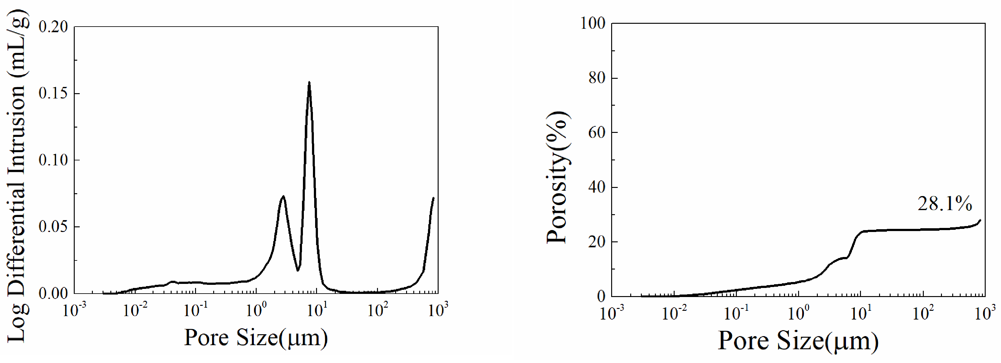
The overall methodology framework of this study, from material preparation to the final kinetic modeling, is illustrated in Figure 1. Commercial hematite pellets were used as the raw material for the reduction experiments. The pellets had an average diameter of 15.2 mm with a standard deviation of 1.37 mm, and their porosity was measured to be about 28% by mercury porosimetry. As shown in Table 1, the specimens exhibited a typical chemical composition for hematite pellets, with an oxygen concentration of 28.26 wt%. For the determination of the kinetic rate constants, the apparent density of the pellets was calculated to be approximately 2400 kg/m3.
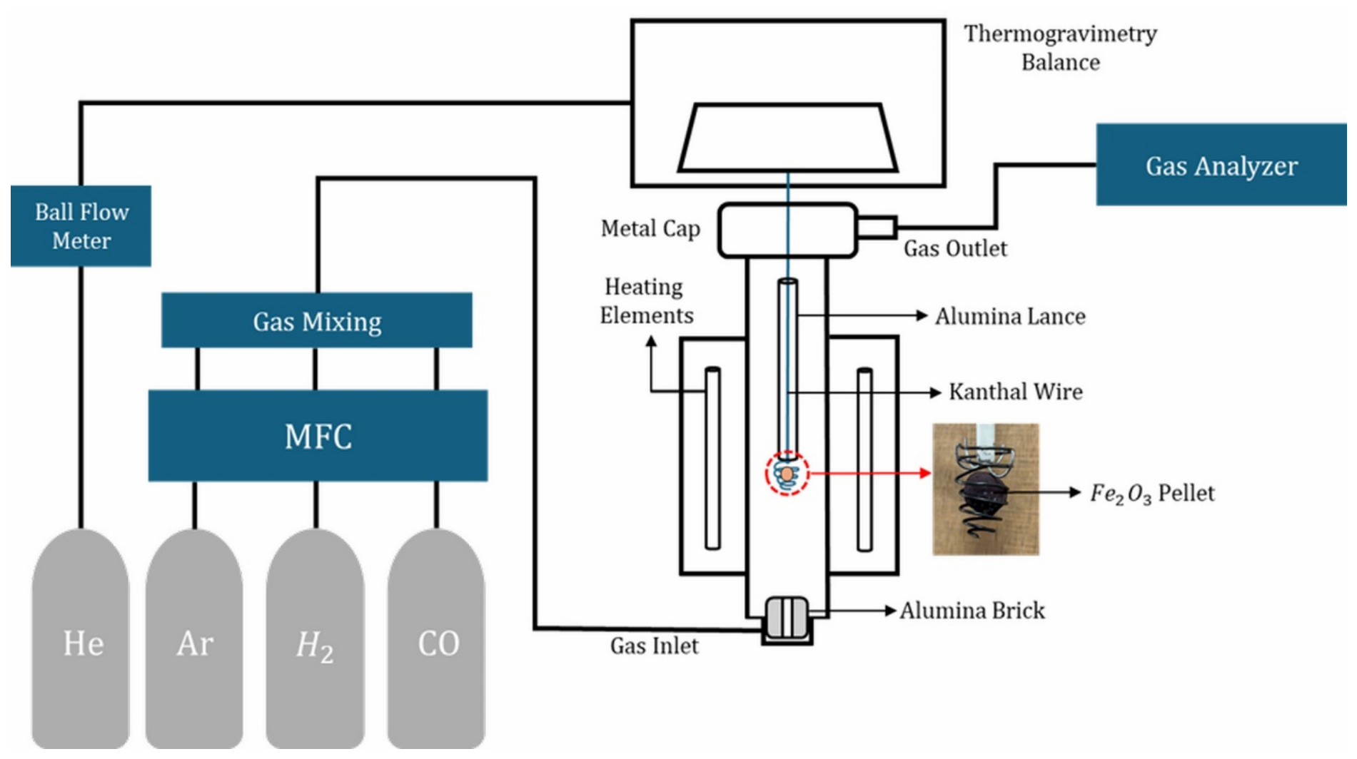
The reduction experiments were carried out using a thermogravimetric analysis (TGA) setup, as described in Figure 2. An electronic balance was installed above a vertical electrical resistance furnace. A Kanthal suspension wire was attached to the bottom of the balance, with its lower end positioned in the isothermal zone of the furnace. To minimize unwanted vibration and signal noise during weight measurement, the wire was shielded by an alumina protective tube. At the end of the wire, a single pellet was suspended in a spiral-shaped holder, which was specifically designed to prevent the blockage of the upward gas stream from the bottom of the furnace. The reducing gas mixture was prepared by controlling the flow rates of individual pure gases and blending them through a static mixer. The total flow rate of the reducing gas was maintained above 1.8 L/min to eliminate the effect of external mass transfer on the overall reaction rate. Furthermore, this sufficient flow rate facilitated the continuous sampling of the exhaust gas by a flue gas analyzer (NOVAprime syngas, MRU GmbH, Neckarsulm, Germany). In addition to the main reducing gas stream, a minimal flow of helium gas was introduced into the balance chamber to protect the microbalance from any adverse effects of the hydrogen-containing atmosphere.
For each experimental run, once the pellet was loaded into the holder and the furnace was sealed, the system was heated to the target reduction temperature (1073, 1123, 1173, 1223 or 1273 K) at a heating rate of 7 K/min under an argon (Ar) atmosphere. It was confirmed that any weight loss during this heating period was negligible. Upon reaching the desired isothermal temperature, the H2-CO reducing gas mixture was introduced to initiate the reduction of iron ore. A systematic experimental design was applied where the temperature and gas mixing ratio were selected as variable parameters to evaluate their kinetic effects, while the total gas flow rate and initial pellet size were strictly fixed to eliminate external mass transfer resistance and geometric variations. The real-time weight change of the pellet was continuously recorded by the electronic balance. After the pre-determined reduction time had elapsed, the gas supply was switched back to the inert Ar gas, and the sample was allowed to cool within the furnace to room temperature. Each measurement was repeated at least twice to ensure reproducibility. Repeated measurements confirmed excellent reproducibility with mostly identical results; a maximum error interval of ~5.7% observed in specific cases was attributed to inherent pellet heterogeneities.

4. Results and Discussion

4.1. Influences of Temperature and Gas Composition

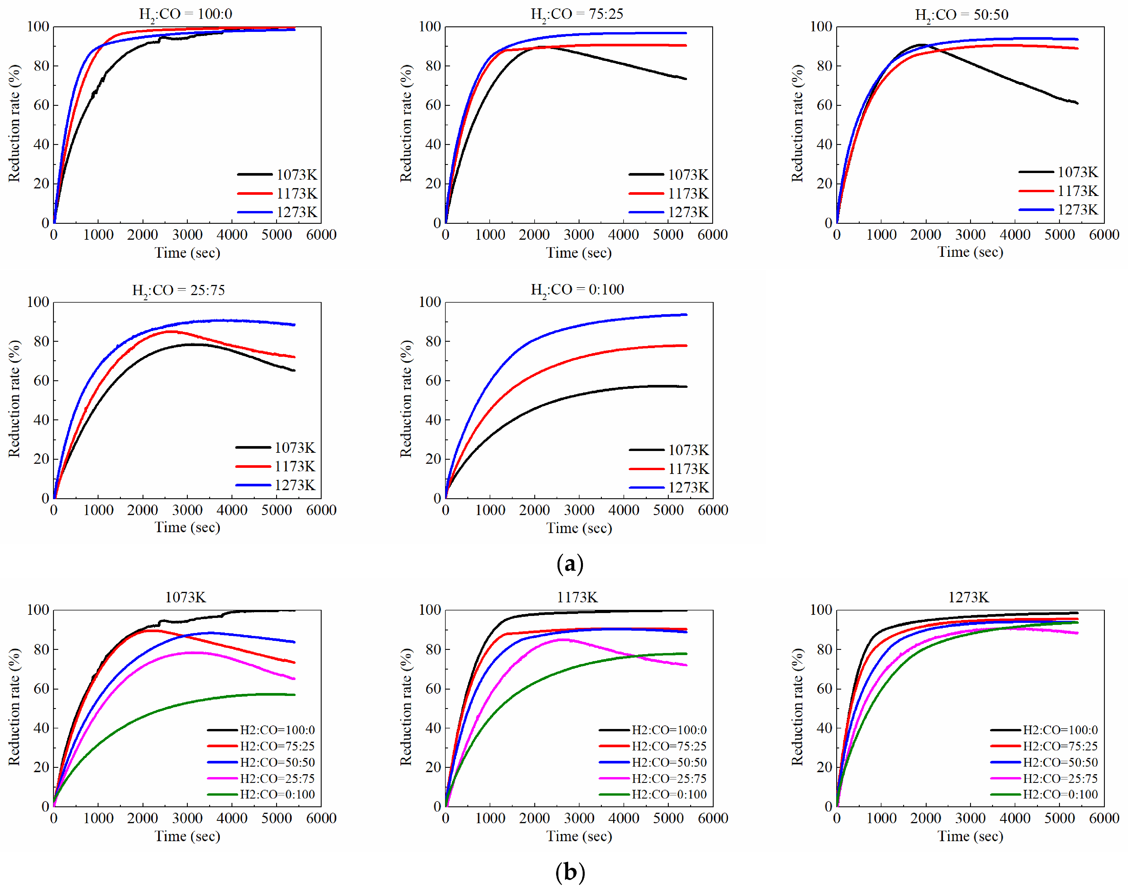
Isothermal reduction experiments of a single hematite pellet were conducted at various temperatures and gas compositions. The reduction rate was calculated using Equation (1), and the results of the measurements are summarized in Figure 3.
r e d u c t i o n   r a t e , % = r e m o v e d   O   b y   r e d u c t i o n , g a m o u n t   o f   O   i n   a   p e l l e t , g × 100
As shown in Figure 3a, the reduction efficiency significantly improves with higher temperatures and increased H2 content. Specifically, under a pure H2 atmosphere (fraction = 1.0), the reduction reached approximately 100% within one hour, regardless of the experimental temperature. Similar dependencies on temperature and gas mixing ratio are also evident in Figure 3b.
It is widely recognized that H2 gas shows superior reduction efficiency for iron ore compared to CO gas, primarily because of its higher diffusivity—approximately four times that of CO. In general, gas diffusion within porous media depends on pore size as well as the mean free path of the diffusing gas. Bulk diffusion is the dominant mechanism only when the pore size is sufficiently larger than the mean free path. Conversely, if the pore size is on a smaller or comparable scale to the mean free path, gas molecules collide more frequently with the pore walls than with each other, thereby restricting diffusion. Therefore, it is essential to compare the initial pore size in the iron ore pellets with the mean free paths of H2 and CO gases under the given experimental conditions. Figure 4 shows the mercury porosimetry results of a hematite pellet, revealing that the majority of the pores in the pellet are concentrated in the size range of 1.0~10 μm (10−6~10−5 m). Meanwhile, the mean free path of a specific gas can be theoretically computed using Equation (2):
λ = k B T 2 π d 2 P
where k B and d represent the Boltzmann constant and the collision diameter of the gas molecule, respectively. In addition, T and P denote the absolute temperature and the pressure, specifically 1 atm for the present estimation. The calculated mean free paths for H2 and CO correspond to 0.47 μm and 0.28 μm, respectively, which are smaller than the pore size in the hematite pellets. Consequently, bulk diffusion can be applied for both H2 and CO gases within the hematite pellets. Since the pores in the pellets will grow due to the removal of oxygen and vacancy formation, the condition for bulk diffusion can be maintained during the initial reduction stage, before a dense iron phase is sufficiently formed at the outer surface.
Beyond these intrinsic diffusion characteristics, an apparent decreasing tendency in the reduction rate was observed during the reaction. This tendency was more noticeable at lower temperatures and higher CO fractions, although the presence of H2 still significantly influenced the overall behavior. This reversal phenomenon in the reduction curve actually indicates a net weight gain of the sample during the experiment, which is attributed to carbon deposition. In fact, this was confirmed by the observation of powdery carbon on the surface of the pellet and around the holder after the experiments. Furthermore, subsequent compositional analysis revealed that the carbon content of the pellet reduced at 1073 K exceeded 4.0 wt%.

4.2. Influences of Carbon Deposition

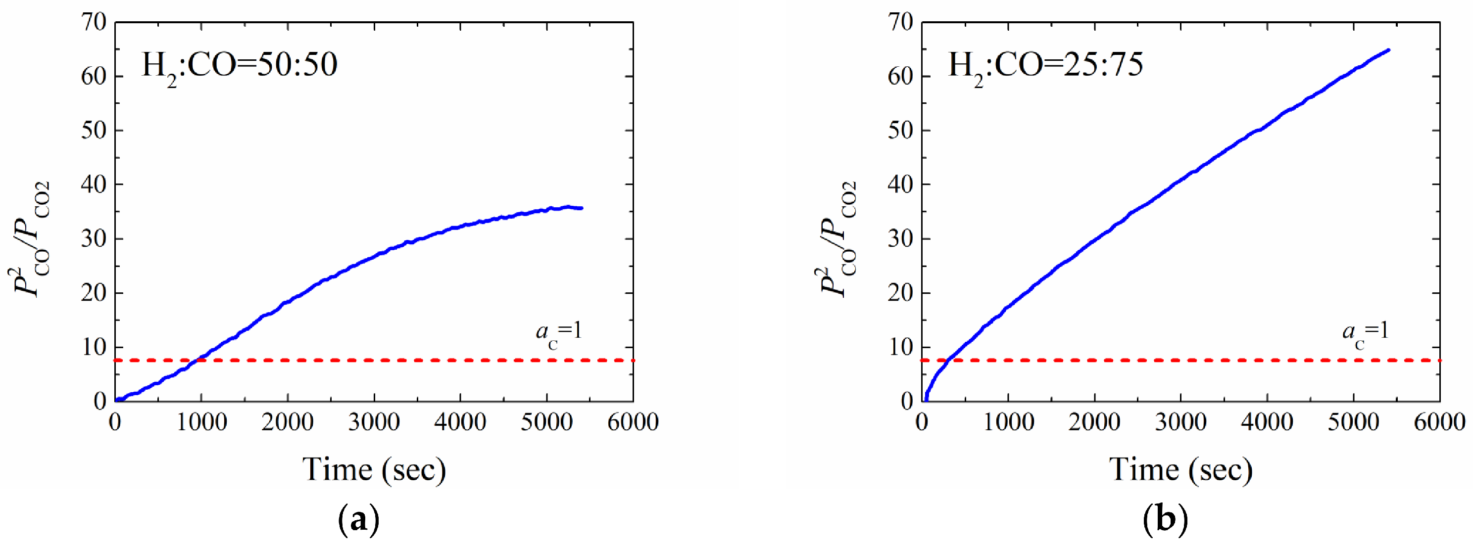
Previous studies have also demonstrated that carbon deposition from CO gas can be accelerated by the catalytic effects of metallic iron, the syngas atmosphere or both [14,15]. This catalytic carburization phenomenon has been widely utilized in various industrial applications, such as blast furnace processes and carbon black production. Considering the inverse Boudouard reaction for solid carbon formation, as shown in Equation (3), the equilibrium activity of solid carbon, a C at a specific temperature can be estimated using the partial pressure ratio of the off-gas.
2 C O g = C O 2 g + C s
As an example, the typical changes in the p C O 2 / p C O 2 ratio, calculated from the analyzed gas composition, are presented in Figure 5. As the reduction takes place, the relative amount of CO over CO2 rapidly increases. Eventually, it crosses the threshold of a C = 1 indicated by the red dashed line, creating a highly favorable condition for solid carbon formation. This thermodynamic shift is significantly more predominant at a higher CO concentration, where the equilibrium activity of solid carbon ratio rises much faster and reaches a higher value compared to the 50:50 condition. Furthermore, this carbon deposition is particularly favored at lower temperatures because the inverse Boudouard reaction is highly exothermic.
Despite these thermodynamic considerations, it is practically impossible to identify the exact onset of carbon formation during the experiments. Consequently, separating the weight gain caused by carbon deposition from the net weight loss to obtain the reduction rate of iron ore is highly challenging. This concurrent nature remains the primary obstacle in accurately measuring the true reduction kinetics and determining the rate-controlling step for hematite pellets.

4.3. Rate-Controlling Step of Initial Reduction in a Hematite Pellet

Detecting the exact onset of carbon deposition in real time is fundamentally limited, which could introduce uncertainty into kinetic calculations. To exclude the interfering effect of carbon deposition, the kinetic analysis was selectively focused on the early stage of the reduction (~1000 s). During this initial period, no carbon formation was observed, and the carbon content in the pellets reduced for 1000 s was found to be no more than 0.025 wt%. Therefore, it was reasonably deduced that any weight gain caused by carbon deposition was negligible, ensuring sufficient reliability of the kinetic analysis during this early stage. Based on this initial reduction rate, which directly corresponds to the net weight loss, the rate-controlling step could be determined using the unreacted core model.
As mentioned in the previous section, the rate-controlling step can be determined by identifying the suitable specific integral kinetic function, g ( x ) of this reduction process. According to Heidari et al. [16], most previous studies utilizing the unreacted core model have established that the overall reduction rate is primarily governed by either the chemical reaction at the interface or gas diffusion through the product layer [17,18,19,20,21,22,23,24,25]. In the present study, therefore, these two potential rate-controlling mechanisms were considered along with the case controlled by both two rate-controlling steps, i.e., mixed control. The specific integral kinetic function, g ( x ) for each rate-controlling step as a determinator can be expressed as follows.
Topochemical   reaction   at   the   interface :   g x = 1 1 x 1 / 3
Gas   diffusion   through   the   product   layer :   g x = 3 2 x 3 1 x 2 / 3
Mixed   control : g x = 1 1 x 1 / 3 + A r 0 C 0 C e q . 3 2 x 3 1 x 2 / 3
Here, C 0 and C e q . stand for the concentration of reducing gas at the outer surface of a pellet and that at the reaction interface, respectively, while r 0 is designated to be the initial diameter of a pellet, and A is a constant, whose value was adopted from the reference [8].
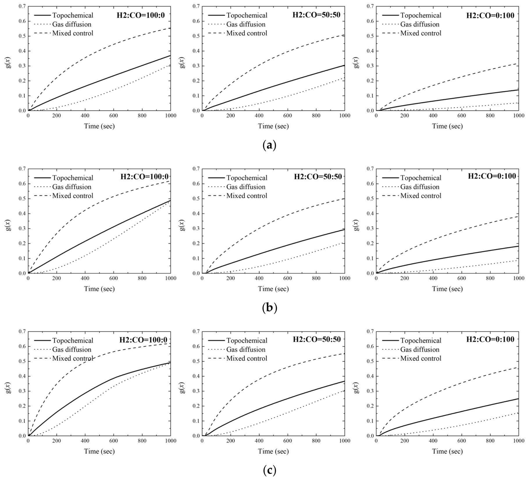
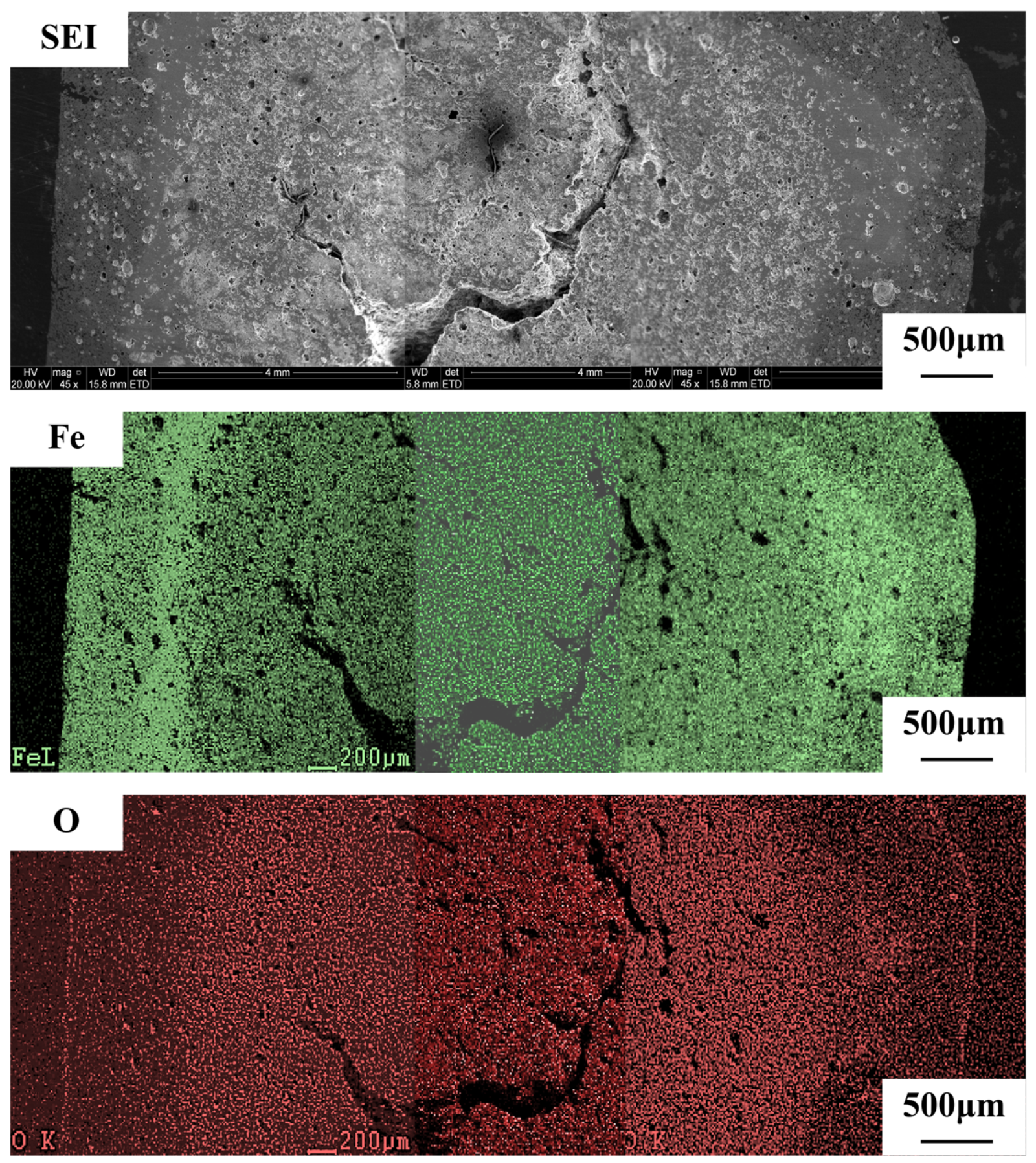
Based on the experimental results obtained under various temperatures and gas mixing ratios, the specific integral kinetic functions, g ( x ) of each rate-controlling mechanism were plotted as a function of time, as shown in Figure 6. The coefficients of determination (R2) are tabulated in Table 2. It is evident that the function corresponding to the topochemical reaction at the interface exhibits the best linearity and the highest R2 value compared to other kinetic mechanisms. This verifies that the early stage of hematite pellet reduction in most experimental conditions is governed by the topochemical reaction at the receding interface. However, in certain cases, the kinetic plot deviates from linearity after approximately 600 s, and this tendency is more pronounced at higher reducing temperatures and increased hydrogen fractions in the gas mixture. Considering that the reduction efficiency is enhanced under these highly reducing conditions, the inward growth of dense reduced iron from the outer surface likely promotes the transition in the rate-controlling step from the topochemical reaction to another kinetic mechanism, which should be gas diffusion through the product layer. The formation of this dense product layer was confirmed through SEM analysis of a pellet reduced for 1000 s, as shown in Figure 7.
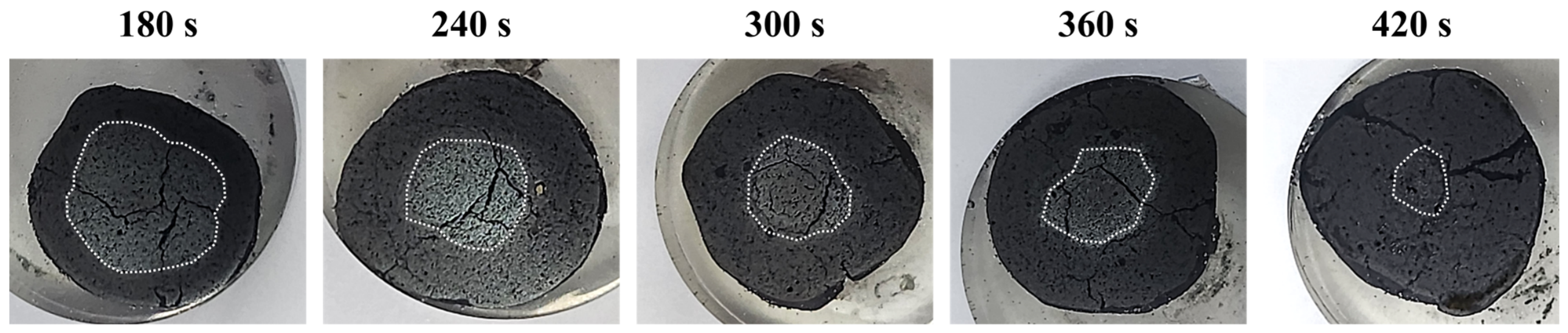
To visually confirm that the initial reduction of the hematite pellets is primarily controlled by the topochemical reaction rate at the interface, the reduction kinetics were investigated through interrupted reduction experiments. The pellets were reduced in a 50 vol% H2–50 vol% CO gas mixture at 1073 K and interrupted at pre-determined times (180, 240, 300, 360, and 420 s). At each specified time, the reducing gas was switched to an inert gas, and the pellet was rapidly withdrawn and quenched under an Ar flow. The partially reduced pellets were then diametrically cross-sectioned for macroscopic observation. Under a light optical microscope, the outer reacted layer and the inner unreacted core were clearly distinguishable by their color and texture, which is a distinct characteristic of the topochemical reaction model at a receding interface. As shown in the cross-sectional macrographs in Figure 8, the area of the unreacted core outlined by the white dashed lines gradually shrinks as the reduction proceeds. Further analysis for phase identification showed that the product layer is wüstite, while the inner core remained unreacted hematite.

4.4. Rate Constant of the Reduction in a Hematite Pellet and Its Temperature Dependence

Since it was proven that the initial stage of reduction of the hematite pellets is primarily controlled by the topochemical reaction rate at the interface, the rate constant k can be obtained from the slope of the g ( x ) versus t plot. Mckewan suggested a mathematical kinetic model, assuming that the reduction rate depends on the interfacial area of the product layer and the unreacted core, as expressed in Equation (4) [26].
r 0 d 0 1 1 x 1 / 3 = k t
Here, r 0 and d 0 denote the radius of a pellet before the reduction and the density of oxygen (kg/m3), respectively. Consequently, the rate constant k can be calculated from the values of the slope in Figure 6 and the measurable properties of the pellets. The evaluation results of the rate constant of reduction are tabulated in Table 3. Here, it should be noted that the degree of reduction was at least 36%, and no trace of a residual hematite or magnetite core was observed in the pellets, even under the least favorable conditions after 1000 s of reduction. Since the present reduction conditions are more than sufficient to complete the reduction step of Fe3O4 → FeO, the present rate constant corresponds to the apparent rate constant for the overall reduction, which includes the sequential reduction steps of Fe2O3 → Fe3O4 and Fe3O4 → FeO. The magnitude of the apparent rate constant for the gaseous reduction in the hematite pellet is found to be in the range of 0.5~2.0 × 10⁻³ (kg/m2∙s), which agrees well with previously reported values under similar experimental conditions [27,28,29]. As expected from the previous discussion, it is clear that the reduction rate constant increases as the temperature rises and the hydrogen concentration in the gas mixture increases.
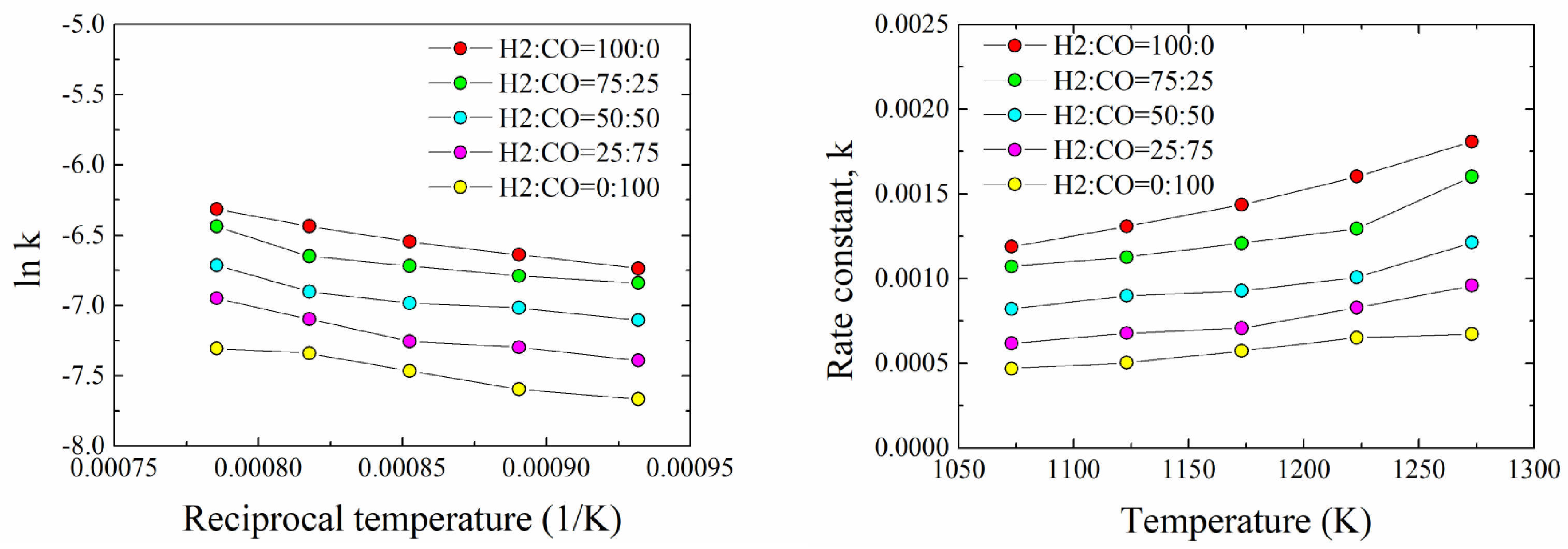
Based on the temperature dependence of the rate constant, the apparent activation energy can be derived using the Arrhenius equation. Figure 9 presents not only the relationships of the rate constant but also the Arrhenius plot, illustrating the relationship between the natural logarithm of the rate constant and the reciprocal of the absolute temperature. Mathematically, the slope of this linear plot corresponds to E a / R , where E a is the activation energy and R is the universal gas constant. The apparent activation energies evaluated for the reduction in the hematite pellets are summarized in Table 4. It should be noted that the activation energy does not vary significantly with the gas mixing ratio, suggesting that the fundamental mechanism of the chemical reaction remains similar regardless of the specific H2:CO proportion. Moreover, the activation energies obtained in the present study are in the range of 20~24 kJ/mol, which are relatively lower compared to the previously reported data summarized in Table 5.
Evidently, the reported activation energies for the reduction of iron oxide vary widely—from a few kJ/mol to over 100 kJ/mol—depending on the initial properties of the iron oxide, the reducing atmosphere, and the rate-controlling step considered. Some studies focusing on the stepwise reduction of iron oxide have shown that the Fe2O3 → Fe3O4 reduction step has higher activation energy than the Fe3O4 → FeO reduction step. As sufficiently explained in the previous section, however, the activation energy obtained in the present study is an apparent value including these sequential steps. Further examination of Table 5 indicates that the activation energy tends to be higher when the particle size is smaller and the rate-controlling step is the chemical reaction at the receding interface, rather than gas diffusion through the product layer.
For a more appropriate comparison with the present findings for hematite pellets, the following analysis focuses solely on previously reported data for iron oxide pellets or briquettes larger than 5 mm. In these cases, the activation energy for the reduction rate constant is substantially lower than that for the reduction in powdery iron oxide, mainly because gas diffusion through the product layer becomes more dominant in controlling the overall rate compared to the chemical reaction at the interface [37]. In fact, many studies utilizing large particles have proposed mixed control involving the gas diffusion through the product layer and the chemical reaction at the interface as the rate-controlling step [18,30,31,32]. This mixed control can be understood as a transition of the rate-controlling step from the chemical reaction at the interface to the gas diffusion through the product layer, as the outer product layer, which is considerably dense in many cases, grows inward during the reduction process [31,32]. Therefore, the present results, which suggested that the reduction rate of hematite pellets at the initial stage (~1000 s) is controlled by the chemical reactions at the interface are well consistent with those previous studies. As is well known, H2 has far higher diffusivity and transports even in the reduction environment much faster than CO gas. This difference results in a higher reduction rate for H2 gas compared to CO gas reduction. When the overall rate is controlled by the interfacial chemical reaction, however, the influence of the gas composition on the reduction rate and the activation energy should be less significant, which perfectly aligns with the independence of the activation energy from the gas atmosphere observed in the present study.
Furthermore, El-Geassy et al. investigated the effect of porosity on the reduction kinetics and the activation energy [11]. It was demonstrated that the activation energy is lower when the iron oxide is more porous and less dense, which enables easier gas transport. It is also noteworthy that fired briquettes before the reduction in the study by Moon et al. had approximately 22% porosity, and the activation energy for the reduction was no more than 30 kJ/mol [31]. Considering the comparatively high porosity of the hematite pellets in the present study, the correspondingly low value of the activation energy is highly comprehensible.

5. Summary

In this study, the initial reduction kinetics of single hematite pellets using H2-CO gas mixtures were systematically investigated through thermogravimetric analysis (TGA) at 1073–1273 K. Due to the concurrent catalytic carbon deposition under high CO concentration and low temperatures, measuring the precise net weight loss for reduction was highly challenging. To prevent this interference, the kinetic evaluation was focused on the initial reduction stage (within 1000 s), yielding the following principal findings:
(1)
The macroscopic reduction rate significantly accelerated with elevated temperatures and increased H2 fractions, inherently benefiting from the superior diffusivity of H2. Based on the mean free path evaluations, bulk diffusion was confirmed as the dominant gas transport mechanism within the porous pellets.
(2)
Kinetic modeling coupled with cross-sectional macroscopic observations verified that the initial reduction stage is primarily governed by the topochemical reaction at the receding interface. This mechanism effectively incorporates the sequential intermediate phase transformations from hematite to wüstite.
(3)
The apparent rate constants, k for the overall initial reduction were derived in the range of 0.47~1.81 × 10⁻³ kg/m2·s. Accordingly, the apparent activation energies ( E a ) were calculated to range from 20.0 to 24.3 kJ/mol.
(4)
Notably, the apparent activation energy remained largely independent of the H2:CO gas mixing ratio, strongly indicating that the fundamental interfacial chemical reaction dictates the overall rate regardless of the specific gas atmosphere. Furthermore, the relatively low activation energies are physically well-justified by the high initial porosity of the hematite pellets, which facilitates easier intraparticle gas transport.
Practically, these quantitative kinetic parameters and mechanistic insights provide essential knowledge for optimizing gas compositions and operational conditions in the transition toward hydrogen-based direct reduction processes for iron ore. Since this study only focuses on the initial reduction stage to avoid carbon formation, future research should explore methods to evaluate the later-stage reduction kinetics and to independently determine the kinetic parameters for the FeO → Fe reduction step.

Author Contributions

Conceptualization, Y.K.; methodology, Y.K.; formal analysis, H.-J.Y.; investigation, J.L.; resources, J.L.; data curation, J.L.; writing—original draft preparation, Y.K.; writing—review and editing, Y.K.; visualization, J.L.; supervision, Y.K.; project administration, H.K.; funding acquisition, Y.K. All authors have read and agreed to the published version of the manuscript.

Funding

This work was partly supported by the Korea Institute of Energy Technology Evaluation and Planning (KETEP) and the Ministry of Climate, Energy and Environment (MCEE) of the Republic of Korea (No. RS-2022-KP002761) and by the Korea Planning and Evaluation Institute of Industrial Technology (KEIT) grant funded by Ministry of Trade, Industry and Resources (MOTIR) of the Republic of Korea (No. RS-2024-00431461).

Data Availability Statement

The original contributions presented in this study are included in the article. Further inquiries can be directed to the corresponding author.

Conflicts of Interest

Author Hyuk Kim was employed by the company Hyundai Steel. The remaining authors declare that the research was conducted in the absence of any commercial or financial relationships that could be construed as a potential conflict of interest.

References

  1. Celada, J.; Skelly, J. The HyL Process (STEEL SYMP.1963/TECHNICAL PAPER/B.6). In Proceedings of the United Nations Interregional Symposium on the Application of Modern Technical Practices in the Iron and Steel Industry to Developing Countries, Prague, Czech Republic, 11–16 November 1963. [Google Scholar]
  2. Twidwell, L.G. Direct Reduction: A Review of Commercial Processes; Report No. EPA-600/2-80-036; U.S. Environmental Protection Agency, Industrial Environmental Research Laboratory: Research Triangle Park, NC, USA, 1980. [Google Scholar]
  3. Towhidi, N.; Szekely, J. Reduction kinetics of commercial low-silica hematite pellets with CO-H2 mixtures over temperature range 600–1234 °C. Ironmak. Steelmak. 1981, 6, 237–249. [Google Scholar]
  4. Shams, M.; Valipour, M.S. Analysis of the performance of a shaft furnace for the direct reduction of iron ore. Appl. Math. Model. 2012, 36, 6211–6224. [Google Scholar]
  5. Quintero, R.; Martinez-Vera, E. Operating Experiences and Results of HYL III Plants. In Proceedings of the ISS Ironmaking Conference Proceedings; Iron & Steel Society: Warrendale, PA, USA, 1984; Volume 43. [Google Scholar]
  6. Takenaka, Y.; Kimura, Y.; Narita, K.; Kaneko, D. Mathematical Model of Direct Reduction Shaft Furnace and Its Application to Actual Operations. Comput. Chem. Eng. 1986, 10, 67–75. [Google Scholar] [CrossRef] [Scilit]
  7. Zuo, H.B.; Wang, C.; Dong, J.J.; Jiao, K.X.; Xu, R.S. Reduction kinetics of iron oxide pellets with H2 and CO mixtures. Int. J. Miner. Metall. Mater. 2015, 22, 688–696. [Google Scholar] [CrossRef] [Scilit]
  8. Tsay, Q.T.; Ray, W.H.; Szekely, J. The modeling of hematite reduction with hydrogen plus carbon monoxide mixtures: Part I. The behavior of single pellets. AIChE J. 1976, 22, 1064–1072. [Google Scholar] [CrossRef] [Scilit]
  9. Valipour, M.S.; Saboohi, Y. Numerical investigation of isothermal reduction of hematite pellet with H2, CO and H2-CO mixtures. Ironmak. Steelmak. 2007, 34, 121–128. [Google Scholar]
  10. Towhidi, N.; Szekely, J. The influence of carbon deposition on the reduction kinetics of commercial grade hematite pellets with CO, H2, and N2. Metall. Trans. B 1983, 14, 359–367. [Google Scholar] [CrossRef] [Scilit]
  11. El-Geassy, A.A. Gaseous reduction of iron ore pellets under conditions of carbon deposition. ISIJ Int. 1998, 38, 334–343. [Google Scholar]
  12. Pineau, A.; Kanari, N.; Gaballah, I. Kinetics of reduction of iron oxides by H2 and CO mixtures. Thermochim. Acta 2006, 447, 89–100. [Google Scholar] [CrossRef] [Scilit]
  13. Hayashi, S.; Iguchi, Y. Factors affecting the sticking of iron ore pellets during reduction. ISIJ Int. 1992, 32, 962–971. [Google Scholar] [CrossRef] [Scilit]
  14. Walker, P.L. Carbon formation from carbon monoxide-hydrogen mixtures over iron catalysts: II. Rates of carbon formation. J. Phys. Chem. 1959, 63, 140. [Google Scholar] [CrossRef] [Scilit]
  15. Turkdogan, E.T. Catalytic effect of iron on decomposition of carbon monooxide: I. Carbon deposition in H2-CO mixtures. Metall. Trans. 1974, 5, 11. [Google Scholar] [CrossRef] [Scilit]
  16. Heidari, A.; Niknahad, N.; Iljana, M.; Fabritius, T. A Review on the Kinetics of Iron Ore Reduction by Hydrogen. Materials 2021, 14, 7540. [Google Scholar] [CrossRef] [Scilit] [PubMed]
  17. Turkdogan, E.T.; Vinters, J.V. Gaseous reduction of iron oxides: Part, I. Reduction of hematite in hydrogen. Metall. Mater. Trans. B 1971, 2, 3175–3188. [Google Scholar] [CrossRef] [Scilit]
  18. El-Geassy, A.A.; Shehata, K.A.; Ezz, S.Y. Mechanism of Iron Oxide Reduction with Hydrogen/Carbon Monoxide Mixtures. Trans. Iron Steel Inst. Jpn. 1977, 17, 629–635. [Google Scholar] [CrossRef] [Scilit]
  19. Bonalde, A.; Henriquez, A.; Manrique, M. Kinetic analysis of the iron oxide reduction using hydrogen-carbon monoxide mixtures as reducing agent. ISIJ Int. 2005, 45, 1255–1260. [Google Scholar] [CrossRef] [Scilit]
  20. Corbari, R.; Fruehan, R.J. Reduction of iron oxide fines to wustite with CO/CO2 gas of low reducing potential. Metall. Mater. Trans. B 2010, 41, 318–329. [Google Scholar] [CrossRef] [Scilit]
  21. Sohn, I.; Jung, S.M. Effect of metal additions to the reduction of iron oxide composite pellets with hydrogen at moderate temperatures. Steel Res. Int. 2011, 82, 1345–1354. [Google Scholar] [CrossRef] [Scilit]
  22. Yi, L.; Huang, Z.; Peng, H.; Jiang, T. Action rules of H2 and CO in gas-based direct reduction of iron ore pellets. J. Cent. South. Univ. 2012, 19, 2291–2296. [Google Scholar] [CrossRef] [Scilit]
  23. Kapelyushin, Y.; Xing, X.; Zhang, J.; Jeong, S.; Sasaki, Y.; Ostrovski, O. Effect of Alumina on the Gaseous Reduction of Magnetite in CO/CO2 Gas Mixtures. Metall. Mater. Trans. B 2015, 46, 1175–1185. [Google Scholar] [CrossRef] [Scilit]
  24. Qie, Y.; Lyu, Q.; Liu, X.; Li, J.; Lan, C.; Liu, X. Effect of hydrogen addition on reduction behavior of iron oxides in gas-injection BF. ISIJ Int. 2017, 57, 404–412. [Google Scholar] [CrossRef] [Scilit]
  25. Kazemi, M.; Pour, M.S.; Sichen, D. Experimental and Modeling Study on Reduction of Hematite Pellets by Hydrogen Gas. Metall. Mater. Trans. B 2017, 48, 1114–1122. [Google Scholar] [CrossRef] [Scilit]
  26. Mckewan, W.M. Kinetics of iron oxide reduction. Trans. Metall. Soc. AIME 1960, 218, 2–6. [Google Scholar]
  27. Kawasaki, E.; Sanscrainte, J.; Walsh, T.J. Kinetics of reduction of iron oxide with carbon monoxide and hydrogen. AIChE J. 1962, 8, 48–52. [Google Scholar] [CrossRef] [Scilit]
  28. Yang, H.Y.; Kim, H.S. Study on the kinetics of direct reduction of sintered ferric oxide-lime pellets. J. Korean Inst. Met. 1972, 10, 25–38. [Google Scholar]
  29. Kang, T.I. Study of Reduction Kinetics and Properties of Iron Oxides for COREX Process. Master’s Thesis, The University of New South Wales, Kensington, Australia, 2000. [Google Scholar]
  30. Abd Elhamid, M.H.; Khader, M.M.; Mahgoub, A.E.; El Anadouli, B.E.; Ateya, B.G. Autocatalytic Reduction of Hematite with Hydrogen under Conditions of Surface Control: A Vacancy-Based Mechanism. J. Solid State Chem. 1996, 123, 249–254. [Google Scholar] [CrossRef] [Scilit]
  31. Nasr, M.I.; Omar, A.A.; Hessien, M.M.; El-Geassy, A.A. Carbon monoxide reduction and accompanying swelling of iron oxide compacts. ISIJ Int. 1996, 36, 164–171. [Google Scholar] [CrossRef] [Scilit]
  32. Moon, I.J.; Rhee, C.H.; Min, D.J. Reduction of hematite compacts by H2-CO gas mixtures. Steel Res. 1998, 69, 302. [Google Scholar] [CrossRef] [Scilit]
  33. Mondal, K.; Lorethova, H.; Hippo, E.; Wiltowski, T.; Lalvani, S.B. Reduction of iron oxide in carbon monoxide atmosphere-reaction controlled kinetics. Fuel Process. Technol. 2004, 86, 33–47. [Google Scholar] [CrossRef] [Scilit]
  34. Kuila, S.K.; Chaudhuri, S.; Chatterjee, R.; Ghosh, D. Reduction of Magnetite Ore Fines with Hydrogen. In Proceedings of the International Conference on Chemical Engineering, Dhaka, Bangladesh, 29–30 December 2014; pp. 81–85. [Google Scholar]
  35. Barde, A.A.; Klausner, J.F.; Mei, R. Solid state reaction kinetics of iron oxide reduction using hydrogen as a reducing agent. Int. J. Hydrogen Energy 2016, 41, 10103–10119. [Google Scholar] [CrossRef] [Scilit]
  36. El-Geassy, A.A. Rate Controlling Step in the Reduction of Iron Oxides; Kinetics and Mechanism of Wüstite-Iron Step in H2, CO and H2/CO Gas Mixtures. IOP Conf. Ser. Mater. Sci. Eng. 2017, 229, 012002. [Google Scholar] [CrossRef] [Scilit]
  37. Oh, J.; Noh, D. The reduction kinetics of hematite particles in H2 and CO atmospheres. Fuel 2017, 196, 144–153. [Google Scholar] [CrossRef] [Scilit]
  38. Bai, M.-H.; Long, H.; Ren, S.-B.; Liu, D.; Zhao, C.-F. Reduction Behavior and Kinetics of Iron Ore Pellets under H2–N2 Atmosphere. ISIJ Int. 2018, 58, 1034–1041. [Google Scholar] [CrossRef] [Scilit]
  39. Tang, Q.; Huang, K. Determining the kinetic rate constants of Fe3O4-to-Fe and FeO-to-Fe reduction by H2. Chem. Eng. J. 2022, 434, 134771. [Google Scholar] [CrossRef] [Scilit]
  40. Cheng, Q.; Guo, H.; Yan, B. Kinetics and microstructural evolution of iron oxide pellets reduced by H2/CO mixtures: Implications for hydrogen-based direct reduction. Int. J. Hydrogen Energy 2026, 205, 153100. [Google Scholar] [CrossRef] [Scilit]
Figure 1. Flowchart of the overall experimental and kinetic analysis procedures.
Metals 16 01045 g001
Figure 2. Schematic illustration of experimental apparatus.
Metals 16 01045 g002
Figure 3. Reduction rate with (a) various temperatures and (b) gas mixing ratio.
Metals 16 01045 g003
Figure 4. Pore size distribution and porosity of a hematite pellet.
Metals 16 01045 g004
Figure 5. Change in the partial pressure ratio with time at 1073K. (a) H2:CO = 50:50, (b) H2:CO = 25:75. The horizontal red dashed line indicates a carbon activity of 1.
Metals 16 01045 g005
Figure 6. The specific integral kinetic functions for rate-controlling mechanisms under various reducing conditions for (a) 1073 K, (b) 1173 K, and (c) 1273 K.
Metals 16 01045 g006
Figure 7. SEM micrograph and EDS elemental mapping of the cross-section of a pellet reduced by H2:CO = 100:0 at 1073 K for 1000 s.
Metals 16 01045 g007
Figure 8. Optical photographs of the cross-section of pellets partially reduced by H2:CO = 50:50 at 1073 K.
Metals 16 01045 g008
Figure 9. Reduction rate constant of a hematite pellet as the function of temperature.
Metals 16 01045 g009
Table 1. Chemical composition of hematite pellets.
Fe2O3FeOSiO2Al2O3CaOMgOT-FeO
wt%94.10.32.60.42.50.165.628.26
Table 2. Coefficients of determination (R2) of the specific integral kinetic functions for the evaluated kinetic models (The highest R2 values are presented in bold).
TemperatureH2:CO RatioKinetic Models
TopochemicalGas DiffusionMixed Control
1073 K100:099.86%97.17%89.08%
75:2599.98%96.31%97.55%
50:5099.92%96.63%97.99%
25:7599.91%96.29%98.68%
0:10099.74%96.91%98.92%
1173 K100:099.90%97.60%96.18%
75:2599.97%96.78%97.04%
50:5099.89%96.82%97.99%
25:7599.60%97.92%97.53%
0:10099.29%98.19%97.71%
1273 K100:098.36%99.50%93.01%
75:2599.26%99.15%94.33%
50:5099.53%98.45%96.22%
25:7599.51%98.48%96.25%
0:10099.42%98.01%97.90%
Table 3. Rate constant (kg/m2∙s) of the initial reduction in a hematite pellet at various temperatures and gas mixing ratio.
H2:CO Ratio1073 K1123 K1173 K1223 K1273 K
100:011.9 × 10−413.1 × 10−414.3 × 10−416.0 × 10−418.1 × 10⁻⁴
75:2510.7 × 10−411.3 × 10−412.1 × 10−412.9 × 10−416.0 × 10⁻⁴
50:508.21 × 10−49.12 × 10−49.27 × 10−49.71 × 10−412.1 × 10⁻⁴
25:756.17 × 10−46.77 × 10−47.07 × 10−48.27 × 10−49.59 × 10⁻⁴
0:1004.69 × 10−45.03 × 10−45.72 × 10−46.50 × 10−46.71 × 10−4
Table 4. Apparent activation energies for the reduction in the hematite pellets.
H2:CO RatioActivation Energy (J/mol)
100:023,631.7
75:2521,146.8
50:5020,095.5
25:7524,358.2
0:10022,201.0
Table 5. Comparative analysis of kinetics and activation energy for the reduction of iron oxides under H2- and CO-based atmospheres.
Raw
Materials
Temperature
(K)
Reducing
Gas
Particle
Size
(µm)
Activation
Energy
(kJ/mol)
Rate
Controlling Step
Final Product
Phase
Source
Hematite
(Fe2O3)
1073~1473Pure CO900064Chemical
reaction
at metal-oxide
interface
Metallic
iron (Fe)
[28]
Calcium
Ferrites
1173~1373Pure CO10,000
~10,800
61.1
~69.5
Hematite
(Dense)
973~1373100~0% H2 + CO 0~100%980031.6
~53.6
Chemically
controlled &
Mixed control
α-Fe,
Fe3C
[18]
Hematite
(Porous)
973~1373100~0% H2 + CO 0~100%10,8009.5
~21.5
Gaseous
diffusion
controlled
Hematite
(sintered
pellets)
573~773H2
(0.65 atm)
13,00030.1Surface
chemisorption
Fe3O4[30]
Hematite
(Fe2O3)
briquette
973~1373Pure COd8000
h8000
15.0
~28.9
Mixed control
(gaseous diffusion/interfacial reaction)
Metallic
iron (Fe)
[31]
Hematite
(Fe2O3)
briquette
1073~1223Pure CO17,80019.8Mixed control
(interfacial
reaction→
gaseous
diffusion)
Metallic
iron (Fe)
[32]
Hematite
(Fe2O3)
briquette
1073~1223Pure H217,80042.1
Hematite
(Fe2O3)
1073~1173Pure CO1.2,
58.6
10.0
~14.7
Reaction
controlled
kinetics
Metallic
iron (Fe)
[33]
Hematite
(α-Fe2O3)
493~953Pure H21~2 75.9 Nucleation and Growth
(2- and 3D) &
Phase-boundary-controlled reaction
Fe3O4[12]
Hematite
(α-Fe2O3)
493~95310% H2 + 90% N21~2 94.8
Hematite
(α-Fe2O3)
493~953 Pure CO 1~2 114.1
Magnetite (Fe3O4)493~953Pure H21~239
~88
Nucleation and Growth
(2- and 3D) &
Phase-boundary-controlled reaction
Metallic
iron
(α-Fe)
[12]
Magnetite (Fe3O4)493~95310% H2 +90% N21~235.9
~103
Magnetite (Fe3O4)493~953 Pure CO 1~240.3
~114.2
α-Fe,
Fe3C
Magnetite
(Ore fines)
973~1173H2
(0.5~1 atm)
75~18011~33Pore diffusionMetallic
iron (Fe)
[34]
Magnetite
(MSPS *)
1073~1273Pure H263~7547.2Phase
boundary controlled
Wüstite
(FeO)
[35]
Wüstite
(MSPS *)
1073~1273Pure H263~7529.7Metallic
iron (Fe)
[35]
Wüstite
(FeO)
1173~13730~100% H2 + CO50~15053.8
~134.0
Interfacial chemical
reaction
Metallic
iron (Fe)
[36]
Wüstite
(SiO2-doped)
1173~13730~100% H2 + CO50~15028.3
~58.4
Hematite
(Fe2O3)
823~1573Pure H2
/Pure CO
0.74
(mean)
13.5 (H2),
2.3 (CO)
Phase-boundary-controlled
reaction
Metallic
iron (Fe)
[37]
Hematite
(iron ore
pellets)
1033~127375% H2 + 25% N210,000
~12,500
41.0Interfacial chemical
reaction
Metallic
iron (Fe)
[38]
Magnetite (Fe3O4)773~8235~20% H2 + Ar0.0340.1
~50.6
1-dimensional nucleation
and growth
Metallic
iron (Fe)
[39]
Wüstite
(FeO)
973~11235~20% H2 + Ar0.0323.9
~29.0
Hematite
(Fe2O3)
1123 ~ 1273H2 + CO
+10% Ar
9900~10,10047.7Spherical Shrinking ModelMetallic
iron (Fe)
[40]
*: Magnetically stabilized porous structure.
Disclaimer/Publisher’s Note: The statements, opinions and data contained in all publications are solely those of the individual author(s) and contributor(s) and not of MDPI and/or the editor(s). MDPI and/or the editor(s) disclaim responsibility for any injury to people or property resulting from any ideas, methods, instructions or products referred to in the content.