Review

Recent Advances in Joining Technologies for Aluminum/Magnesium Dissimilar Metals: A Review

by
Tianwei Qiu
1,2 and
Muhammed Nafis Bin Osman Zahid
2,*
1
School of Mechanical Engineering, Shandong Huayu University of Technology, Dezhou 253034, China
2
Faculty of Manufacturing and Mechatronic Engineering Technology, Universiti Malaysia Pahang Al-Sultan Abdullah, Pekan 26600, Pahang, Malaysia
*
Author to whom correspondence should be addressed.
Metals 2026, 16(7), 804; https://doi.org/10.3390/met16070804
Submission received: 15 June 2026 / Revised: 9 July 2026 / Accepted: 10 July 2026 / Published: 17 July 2026

Abstract

Aluminum/magnesium (Al/Mg) hybrid structures are promising candidates for lightweight engineering, but reliable joining is still limited by brittle intermetallic compounds (IMCs), oxide films, pores, cracks, and corrosion-related degradation. This review summarizes recent advances in Al/Mg dissimilar-metal joining, including solid-state welding, fusion welding, brazing, resistance-based joining, and mechanical joining. Emphasis is placed on process characteristics, interfacial reactions, defect formation, mechanical properties, service reliability, and simulation-assisted process understanding. The reviewed studies indicate that joint reliability cannot be interpreted solely from IMC thickness; phase type, continuity, spatial distribution, interfacial morphology, and involvement in the fracture path are also critical. Solid-state and high-speed impact processes can restrict continuous Al–Mg reaction layers by reducing thermal exposure and promoting plastic contact, whereas fusion-based processes provide greater manufacturing flexibility but require stricter control of molten-pool behavior, Mg evaporation, porosity, and interlayer stability. Recent numerical simulations and data-driven studies are further discussed as tools for mechanism-guided parameter design. This review provides an integrated comparison of joining routes and highlights future needs for standardized testing, fatigue and corrosion evaluation, thermal-cycling assessment, coupled service-performance analysis, and process selection for engineering applications.

1. Introduction

Lightweight design has become a major development direction in the automotive, rail-transit, and aerospace industries. Aluminum and its alloys are widely used in aerospace, automobile manufacturing, electronics, and related fields because they combine low density, high specific strength, good corrosion resistance, and good thermal and electrical conductivity [1]. Magnesium alloys are even lighter: their density is about two-thirds that of aluminum alloys and only one-quarter that of steels. They are therefore among the lightest structural metallic materials used in manufacturing. Al/Mg hybrid structures combine weight reduction with complementary material properties, making them attractive for lightweight design in multiple industrial fields [2,3].
Reliable Al/Mg joining remains challenging because of the poor metallurgical compatibility and high surface activity of the two metals. During welding or thermo-mechanical joining, limited mutual solubility readily promotes the formation of brittle Al–Mg reaction products at the interface, while oxide films and gas-related defects can also hinder real metallic contact [3,4]. Depending on the joining process, local melting, thermal stress, or unstable material flow may further intensify these problems, leading to cracks, pores, unbonded regions, and unstable load transfer in the joint [5,6,7,8,9].
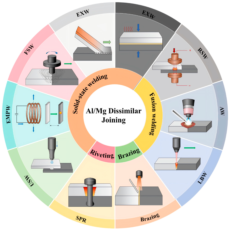
Al/Mg dissimilar-metal joining techniques are generally divided into fusion welding, solid-state welding, brazing, and mechanical joining, as shown in Figure 1 [2,4,8]. Most studies have improved joint quality through process-parameter optimization, interlayer design, surface treatment, external-field assistance, and heat-input control [9,10,11,12]. These strategies aim to suppress continuous brittle IMC layers, reduce welding defects, and improve interfacial bonding and load-bearing capacity.
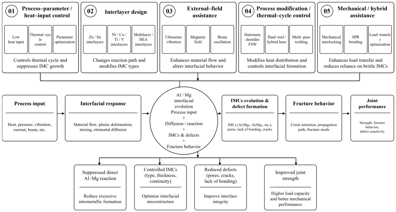
As shown in Figure 2, during Al/Mg joining, heat input, pressure, vibration, impact, interlayers, and external fields govern oxide-film disruption, material flow, elemental diffusion, reaction-layer evolution, and defect formation [13,14,15]. These interfacial changes further determine crack initiation, fracture path, joint strength, corrosion behavior, and fatigue response [16,17]. Therefore, the quality of Al/Mg joints should be evaluated through mechanical performance together with interfacial structure, defect distribution, and service reliability.
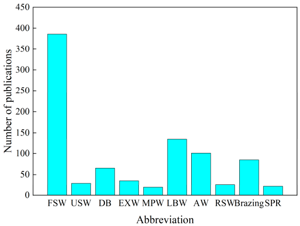
At present, research on Al/Mg dissimilar-metal joining has developed steadily, with clear differences in publication activity among joining routes. For the publication-count analysis, WoS Topic searches were performed by combining Al/Mg-related terms with process-specific terms. For example, the FSW count was obtained using: TS = ((“Al/Mg” OR “Mg/Al” OR “aluminum/magnesium” OR “aluminium/magnesium” OR “magnesium/aluminum” OR “magnesium/aluminium” OR “aluminum magnesium” OR “aluminium magnesium”) AND (“friction stir welding” OR “friction stir lap welding” OR FSW OR FSLW) AND (dissimilar OR joint* OR weld*)). The same search structure was applied to USW, DB, EXW, MPW, LBW, AW, RSW, brazing, and SPR by replacing the process-specific terms. Duplicate records within each process-specific result set were removed using DOI and title matching. As shown in Figure 3, friction stir welding (FSW) remains the most active direction, followed by laser beam welding (LBW), arc welding (AW), brazing, and diffusion bonding (DB), whereas explosive welding (EXW), ultrasonic welding (USW), resistance spot welding (RSW), self-piercing riveting (SPR), and magnetic pulse welding (MPW) have received relatively less attention.
Recent and representative reviews have discussed Al/Mg dissimilar joining from specific viewpoints, particularly friction stir welding, solid-state welding, ultrasonic welding, laser welding, and interlayer-assisted IMC mitigation [3,4,5,6,7,8,9]. These studies have established a useful basis for understanding low-heat-input bonding, material flow, interfacial reactions, and suppression of brittle reaction layers. In addition, recent process-specific studies have reported progress in laser welding, brazing, magnetic pulse welding, resistance spot welding, mechanical joining, corrosion behavior, and fatigue response of Al/Mg joints [10,11,12,13,14,15,16,17]. However, most existing discussions remain centered on a single process family or a specific regulation route, leaving the relationships among joining methods, interfacial defects, service degradation, and process prediction insufficiently integrated.
The present review broadens the scope to solid-state welding, fusion welding, brazing, resistance-based joining, and mechanical joining, and relates the characteristics of each route to interfacial reaction behavior, defect evolution, fracture characteristics, and service reliability. Recent progress in numerical simulation and data-driven prediction is also incorporated to clarify how Al/Mg joining research is moving from empirical parameter optimization toward mechanism-guided process design.

2. Challenges in Aluminum/Magnesium Dissimilar Metals

The main difficulties in Al/Mg dissimilar-metal joining arise from interfacial reactions and defect formation. Although both Al and Mg are lightweight metals with similar melting points, they differ markedly in solid solubility, thermophysical properties, crystal structure, and oxidation behavior. The key physical and chemical properties relevant to Al/Mg joining are summarized in Table 1. In addition, differences in thermal conductivity and thermal expansion behavior can cause uneven heat distribution and residual-stress concentration during welding, making joint quality highly sensitive to process heat input and interfacial conditions [18,19].

2.1. Intermetallic Compounds

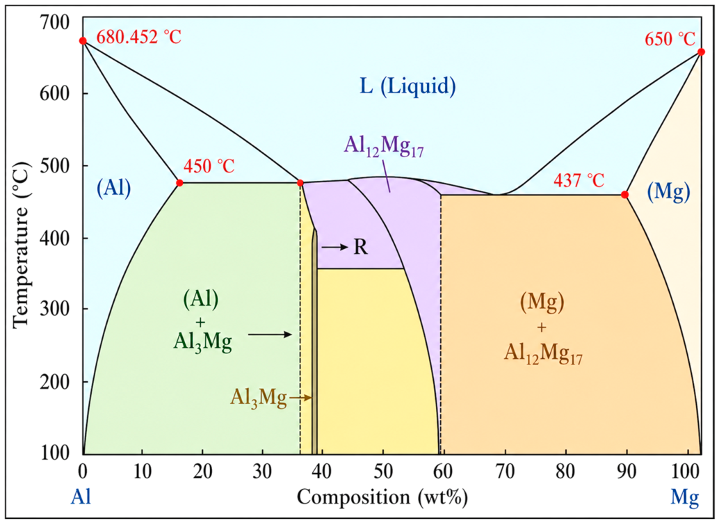
The most critical interfacial reaction in Al/Mg joints is the formation of brittle IMCs, primarily Al3Mg2 and Al12Mg17 (Figure 4). Al and Mg exhibit mutual solubility in the liquid state but only limited solid solubility in the solid state. Under equilibrium conditions, the saturated solubility of Mg in Al is approximately 18.5 at.%, and that of Al in Mg is approximately 11.8 at.%; the mutual solubility decreases further at room temperature. According to the Al–Mg binary phase diagram, a eutectic reaction occurs at approximately 450 °C to form β-Al3Mg2, and γ-Al12Mg17 forms at approximately 437 °C [4]. Moreover, welding processes usually involve rapid cooling and local compositional fluctuations, which may cause interfacial reactions to deviate from equilibrium solidification conditions and broaden the formation range of IMCs.
These IMCs generally possess high hardness and low ductility. For example, previous studies have reported that the microhardness of IMCs formed at the Al/Mg interface can reach 152–221 HV, whereas the average hardness of the Al and Mg base metals is only about 25–60 HV. The property mismatch between the hard, brittle reaction layer and the matrix induces localized stress concentration, thereby facilitating crack initiation at the interface and propagation along the IMC/matrix boundary [20]. Moreover, when the Mg atomic fraction falls within the approximately 40–60% range, a large quantity of IMCs tends to form in the locally mixed zone, degrading the plastic accommodation capability and load-bearing capacity of the joint.
The formation of Al–Mg IMCs cannot be completely avoided in most joining processes. In particular, fusion welding usually accelerates reaction-layer growth because of localized liquid-phase contact. By contrast, solid-state joining can reduce the thickness and continuity of the reaction layer through lower heat input and shorter diffusion time [21,22,23,24,25]. Reliability assessments should therefore account for IMC continuity, local enrichment, and their connection to the main fracture path.

2.2. Defect Formation

2.2.1. Oxide Inclusions

Al and Mg are chemically active and readily react with atmospheric oxygen even at room temperature, forming Al2O3 and MgO. Even after grinding or mechanical cleaning, oxide films can re-form on base-metal surfaces during preparation and assembly. Oxidation becomes more severe as the welding temperature increases. The melting points of both Al2O3 and MgO exceed 2000 °C, far above those of Al and Mg; consequently, these oxides are difficult to melt or expel during welding and tend to remain at the interface or in the weld seam as oxide inclusions.
Oxide inclusions hinder real metallic contact and metallurgical bonding, reducing the effective load-bearing area of the joint. In solid-state joining, insufficient oxide-film fragmentation can leave local unbonded regions at the interface. USW uses high-frequency vibration and pressure to disrupt oxide films and increase the real contact area [26], whereas EXW and MPW rely on high-speed impact and interfacial jetting to remove oxides and expose fresh metallic surfaces [13,27,28]. In fusion welding and brazing, oxide films may become entrapped in the molten pool or retained at the solid–liquid interface, disrupting wetting and serving as nucleation sites for pores or cracks [29,30].

2.2.2. Cracks

Cracking in Al/Mg joints is closely related to the continuity of brittle reaction layers, thermal-stress concentration, and local solidification behavior. During cooling or external loading, a continuous reaction layer cannot deform compatibly with the adjacent Al and Mg matrices, so cracks tend to initiate within the IMC layer, at the IMC/matrix interface, or in locally enriched reaction zones [24,25]. In addition, differences in thermal conductivity and heat capacity can cause asymmetric heat dissipation and residual-stress concentration [19]. In fusion welding, excessive heat input may simultaneously thicken the reaction layer, intensify Mg evaporation, and increase the risk of solidification cracking [21].

2.2.3. Porosity

Porosity mainly originates from gas entrapment and Mg evaporation. Specifically, molten Al and Mg can dissolve gases, and pores remain if trapped bubbles fail to escape before solidification. In high-heat-input processes such as laser welding, arc welding, and resistance spot welding, the low boiling point of Mg makes localized evaporation and metal-vapor recoil more likely. The resulting molten-pool or keyhole instability promotes bubble entrapment, spatter, porosity, and local collapse [10]. In addition, excessive heat input may couple Mg evaporation with reaction-layer growth, reducing both joint formation stability and mechanical performance.
The use of dual magnetic fields combined with ultrasound has been shown to promote bubble escape and suppress pore formation, further indicating that porosity in Al/Mg laser welding is closely related to molten-pool flow and solidification conditions [31].

2.3. Corrosion

Electrochemical corrosion of Al/Mg joints is primarily driven by potential differences among Mg, Al, and interfacial reaction products. In chloride-containing or humid environments, Mg-rich regions preferentially dissolve as anodic sites, whereas Al-rich regions, IMCs, or interlayer-derived phases may behave as relative cathodes. Moreover, welding-induced thermal cycles and plastic deformation further produce layered mixed zones, local compositional gradients, and discontinuous reaction layers, introducing additional micro-galvanic couples [16]. When interlayers are used, the corrosion site may shift from the original Al/Mg interface to the newly formed reaction layer or transition zone [32].

3. Joining Technologies for Al/Mg Dissimilar Metals

3.1. Solid-State Welding

3.1.1. Friction Stir Welding

Friction stir welding (FSW) produces solid-state metallurgical bonding through frictional heating and plastic material flow generated by a rotating tool [33,34]. Its relatively low heat input makes it suitable for lightweight Al/Mg sheet structures; however, joint strength remains strongly dependent on the control of brittle IMCs. Tool rotation speed, welding speed, tool geometry, material configuration, and tool offset jointly affect heat input, material flow, interfacial reactions, and joint strength. Representative optimized parameters are listed in Table 2.
Zhai et al. [41] investigated AZ31B-H24 Mg/6061-T6 Al lap joints to establish correlations among heat transfer, material flow, and joint strength during FSW. Low rotation speed combined with high welding speed reduced heat input, limited material mixing and interdiffusion, and suppressed hook/cold-lap defects and IMC thickening. The joint welded at 600 rpm and 90 mm/min reached approximately 240 N/mm, about twice the lowest value obtained at 1000 rpm and 60 mm/min.
Interlayers regulate Al/Mg interfacial reactions by altering composition-dependent reaction pathways and reducing direct Al–Mg interaction. During FSW, plastic flow disperses the interlayer and changes the reaction route between Al and Mg. Cu and Ni [42,43], Zn [44,45], Sn [46], Pb [47], Cd [48], and Zr [49] interlayers have been reported to reduce direct Al–Mg reactions, although their effectiveness depends strongly on interlayer distribution and on whether the new reaction products remain continuous. Peng et al. [42] studied Cu and Ni powder interlayers in Mg/Al friction stir lap welded (FSLW) joints. Mg–Cu and Al–Cu phases, or Mg–Ni and Al–Ni phases, formed preferentially at the interface. The Cu-interlayer joint showed the highest shear force, 5240 N, which was 41% higher than that of the joint without an interlayer.
Ceramic particles such as SiC [50], TiO2 [51], and TiC [52] can improve the load-bearing capacity of Al/Mg FSW joints through grain refinement and particle pinning, although uniform dispersion remains difficult to achieve. Bagheri Vanani et al. [52] introduced TiC nanoparticles into Al/Mg dissimilar FSW joints and examined their effects on microstructure and mechanical properties. TiC particles promoted grain refinement by facilitating dynamic recrystallization and exerting a Zener pinning effect. A more uniform TiC particle distribution in the stir zone further increased the load-bearing capacity. The optimum joint was obtained at a tool rotation speed of 850 rpm and a welding speed of 50 mm/min, and its tensile strength reached 168 MPa.
Ultrasonic assistance reduces material-flow stress and improves interfacial contact by enhancing plastic deformation and material mixing. In Al/Mg dissimilar-alloy FSW/FSLW, ultrasonic vibration may be introduced from either the tool side or the workpiece side. Tool-side assistance includes axial integration of vibration into the rotating tool or lateral input from the tool side [53], whereas workpiece-side assistance acts on the back surface, side surface, or the region ahead of the stir zone [54]. Its strengthening effects include reduced material flow stress [55], improved plastic flow and interfacial mixing, stronger mechanical interlocking at the Al/Mg interface [56], and restricted growth of a continuous IMC layer [22,23].
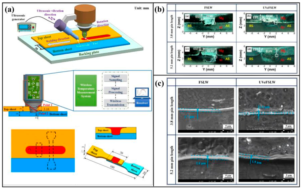
Zhai et al. [56] investigated ultrasonic vibration in Mg/Al FSW joints. Ultrasonic assistance improved material flow in the stir zone and enhanced interfacial mixing, reducing the IMC-layer thickness by approximately 0.5–0.6 μm. The Mg/Al ultrasonic-vibration-enhanced friction stir lap welded (UVeFSLW) joint reached a strength of 290 N/mm, 44 N/mm higher than that of the conventional FSLW joint. The fracture mode also changed from brittle fracture to mixed brittle–ductile fracture, as shown in Figure 5.
Reducing peak temperature and shortening high-temperature residence time are effective ways to suppress IMC growth [57]. Abdollahzadeh et al. [58] introduced TiC nanoparticles into pre-machined grooves on the Mg side and inserted a 0.3 mm Zn foil at the 6061 Al/AZ91 Mg interface to compare FSW joints produced in air and underwater. Water cooling shortened the high-temperature residence time, limiting Al/Mg interdiffusion and localized liquation. The Zn interlayer shifted the reaction products from continuous Al–Mg IMCs to Mg–Zn and Al–Mg–Zn phases, while TiC particles promoted grain refinement. The UWFSW joint showed lamellar intermixing and interpenetrating features in the stir zone; higher h/t and l/t values indicate a more tortuous interface and stronger mechanical interlocking.
Several modified FSW routes have also been developed to regulate material flow and interfacial reactions in Al/Mg joints. In stationary-shoulder FSW, the shoulder remains fixed and the pin provides the main stirring action. This design reduces shoulder-induced frictional heat, improves surface formation, decreases flash and thickness loss, and restricts continuous growth of IMCs at the interface [59]. Double-pass welding modifies the lap interface through a second stirring pass. It can enlarge the effective bonding area and adjust the interfacial overlap morphology, but an excessive overlap ratio or heat input may thicken the IMC layer and weaken the joint [60]. For thick-plate FSW joints, a serrated interlocking structure can be introduced along an inclined interface. This design converts a straight Al/Mg contact interface into a curved mechanical-interlocking path, increases the effective bonding length, and interrupts reaction-layer continuity. Joint strength is then improved through the combined effects of mechanical interlocking and lower continuity of IMCs [61].
Recent friction-stir-based additive and additive-assisted routes provide new possibilities for Al/Mg bimetallic structures. Zhang et al. [62] used friction stir additive manufacturing (FSAM) to fabricate Al/Mg composites and obtained tensile strengths of 215–220 MPa under optimized parameters; however, repeated thermal cycling affected IMC thickness and interfacial cracking behavior. These studies suggest that additive-assisted solid-state joining may broaden Al/Mg structural design, but transition-layer integrity, thermal history, and long-term reliability still require further evaluation.
High-strength Al/Mg FSW joints generally require a balanced heat input: sufficient to promote plastic mixing, but low enough to avoid severe liquation and continuous IMC growth. Tool offset, rotation speed, welding speed, interlayer distribution, ultrasonic vibration, and cooling conditions all act through this balance. A remaining challenge is to connect thermal history and material flow with the real continuity of IMCs and the final fracture path.

3.1.2. Ultrasonic Welding

Ultrasonic welding (USW) produces solid-state bonding by transmitting high-frequency mechanical vibration through a sonotrode to the lap interface. Under pressure, the vibration breaks surface oxide films, promotes localized plastic deformation, and increases the real contact area at the interface [26]. Because of its short welding time, low heat input, and ease of automation, USW has been used for battery tabs, thin sheets, and localized lap structures [63].
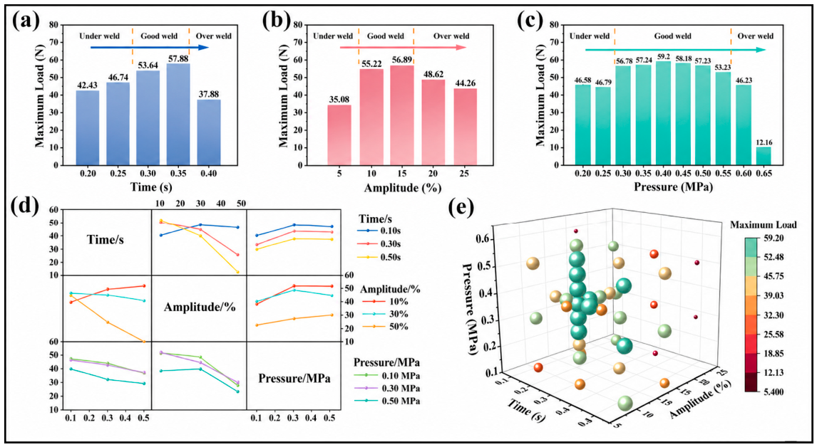
USW joints are governed by a narrow process window. If the energy input is too low, the real contact area remains limited, oxide-film disruption is incomplete, and microweld formation is insufficient. Excessive energy input can reduce load-bearing capacity by inducing severe plastic deformation, local damage, or reaction-layer thickening [64]. Teng et al. [63] confirmed this trend and showed that USW has an optimum window between underwelding and overwelding. At a welding pressure of 0.40 MPa, the maximum joint load reached 59.20 N, and ultrasonic amplitude was the dominant factor controlling joint strength, as shown in Figure 6. Surface condition, assembly configuration, sheet thickness, holding time under pressure [7], lap position [65], and surface texturing [66] also influence the real contact area and fracture path.
Interlayer insertion is a common strategy for regulating Al/Mg interfacial reactions during USW. Zn [26,67], Cu [68], and Ag [69] interlayers can redirect direct Al–Mg reactions toward Mg–X or Al–X reaction systems. Zn interlayers have been studied most widely and can reduce the tendency to form continuous IMCs [26]. Peng et al. [67] further reported that, in ZEK100 Mg/Zn/AA6022 Al joints, the Mg/Zn-side reaction proceeded much faster than the Al/Zn-side reaction, and fracture mainly occurred near the Mg/Zn diffusion layer. In addition, related USW studies without deliberately inserted interlayers have examined the interfacial structure and mechanical properties of Al–Mg sheets [70].
Compared with externally inserted interlayers, an Al cladding layer can act as an intrinsic transition layer and avoid an additional pre-placement step. Dash et al. [17,71] showed that clad-Al layers promoted interfacial mixing and mechanical interlocking in Mg/Al USW joints. However, excessive welding energy still accelerated Al12Mg17 layer thickening and weakened joint reliability; a representative fatigue-deformation mechanism is shown in Figure 7.
USW is most suitable for thin sheets and battery-tab-type lap joints that require short welding time and limited thermal exposure. Its process window remains narrow: insufficient vibration energy produces limited microwelding, whereas excessive energy causes indentation, local damage, and reaction-layer thickening.

3.1.3. Diffusion Bonding

Diffusion bonding promotes interfacial contact and atomic diffusion through the combined control of temperature, pressure, and holding time. Because it is usually performed below the melting points of the base materials, it is suitable for high-precision joining of dissimilar materials [72].
In diffusion bonding, bonding temperature, pressure, and holding time are the primary variables controlling reaction-layer growth and joint microstructure. Azizi et al. [73] reported that higher temperature and longer holding time promoted grain coarsening and thickened the Al12Mg17 and Al3Mg2 layers, while excessive conditions, such as 450 °C for 120 min, reduced the shear strength to 15 MPa. Base alloy composition [74], surface roughness [75], and post-weld annealing [76] also affect interfacial contact, residual stress, and bonding quality.
Interlayers improve Al/Mg diffusion bonding by blocking direct Al/Mg contact and changing the reaction pathway. Table 3 compares representative reaction products and shear strengths obtained with different interlayers.
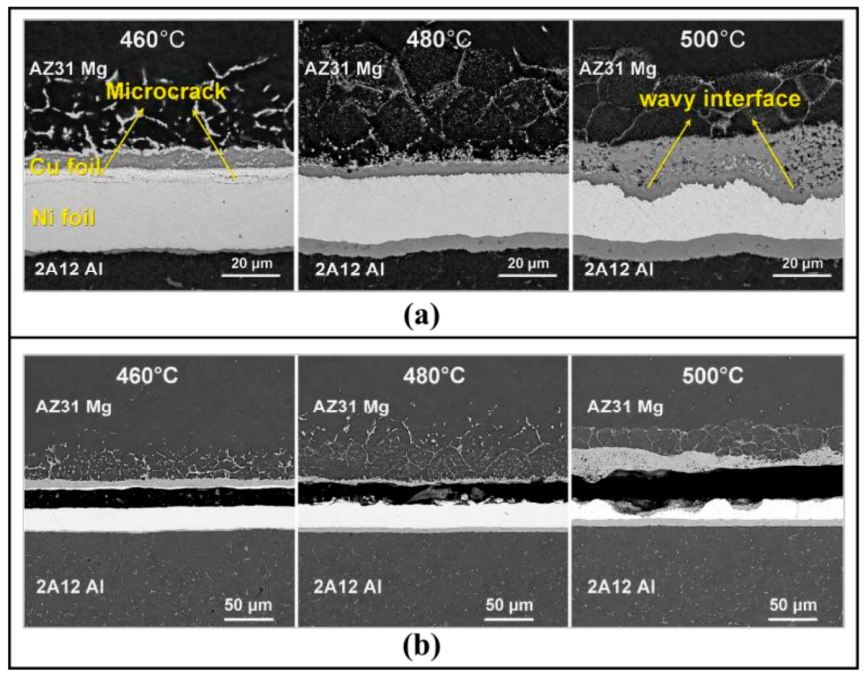
Compared with single interlayers, Ni/Cu composite interlayers can form separate diffusion reaction zones on the Al and Mg sides and improve joint strength. Wang et al. [79] used a Ni/Cu composite interlayer to join 2A12 Al and AZ31 Mg by diffusion bonding. The Ni layer formed Al3Ni2 and Al3Ni on the Al side and blocked direct Al/Mg contact, while the Cu layer produced a Mg–Cu eutectic liquid on the Mg side and improved wetting and atomic migration. As the bonding temperature increased from 460 °C to 500 °C, the Mg-side interface changed from a microcracked or flat morphology to a wavy three-dimensional interface, and the fracture path became more tortuous, as shown in Figure 8. The shear strength increased from 16.18 MPa to 53.78 MPa through the combined effects of metallurgical bonding and mechanical interlocking.
Low-melting-point Zn interlayers mainly improve interfacial contact through liquid-phase wetting and shift the products toward α-Al, MgZn2, and Al–Zn eutectoid phases. Brittle Mg–Zn phases, however, may still limit joint performance [80]. Zn/Sn composite interlayers further use the Zn–Sn eutectic liquid to promote atomic migration and enable more complete bonding at lower temperatures, giving a maximum shear strength of 76.8 MPa [81]. AgCuZn [82], PVD-deposited Ti [83], PVD-deposited Ag [84], and Zn–2Bi [85] interlayers have also been used to regulate reaction products and reaction-layer thickness.
Diffusion bonding provides a controllable interfacial reaction pathway and is useful for investigating diffusion behavior at Al/Mg interfaces. It also requires strict control of surface condition, vacuum, pressure, and holding schedule, and its production efficiency is relatively low. This process is therefore more suitable for high-precision joining, small-batch production, and laminated composite plates.

3.1.4. Explosive Welding

Explosive welding (EXW) uses detonation to drive a flyer plate against a base plate at high velocity. The resulting interfacial jet removes surface oxide films and exposes fresh metallic surfaces, allowing metallurgical bonding within an extremely short time [27,28]. The Al/Mg explosive-welded interface usually shows a straight morphology, a wavy morphology, or a wavy morphology with local vortices. Collision velocity, collision angle, stand-off distance, and explosive loading condition control this morphology. A properly formed wavy interface promotes bonding, whereas excessive process parameters may induce local melting and brittle reaction products [86].
Kumar et al. [87] compared different loading ratios in Al 5052/AZ31B clad plates and found that a lower loading ratio helped produce a stable interface. At R = 0.7, the interface showed small waves, limited local melting zones and IMCs, and no obvious cracks or pores. The maximum tensile and shear strengths reached 167 MPa and 103 MPa, respectively. Inert gas shielding can also reduce oxide entrapment at the interface and improve joint strength [88]. However, EXW still has a narrow processing window and strict safety requirements. More importantly, the interface may become unstable during subsequent annealing or rolling because IMCs can continue to grow.
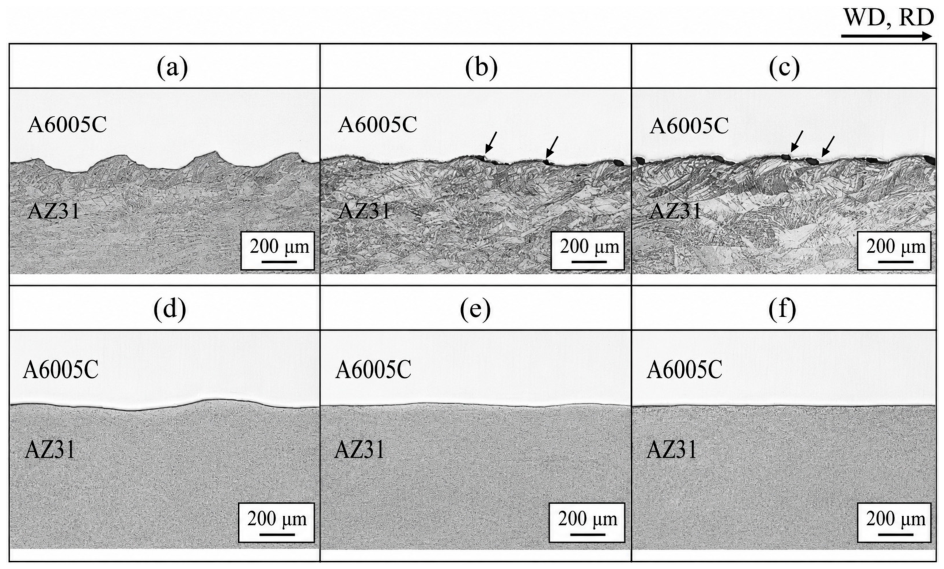
Annealing and rolling are common post-treatments for EXW joints. They can reduce work hardening, release residual stress, and improve clad-plate formability, but they may also thicken the IMC layer [89,90,91]. Hot rolling has therefore been used to improve interfacial compactness and sheet formability [92]. Mihara-Narita et al. [93] examined the effect of hot rolling on the interface. The as-welded Mg/Al explosive-welded joint had a wavy interface with pores in some local regions. After hot rolling, the interface became flatter, pores were compressed and eliminated, and interfacial continuity improved markedly, as shown in Figure 9. Thermal exposure and plastic deformation during hot rolling also promoted diffusion across the Al/Mg interface and changed the reaction layer from a Mg-enriched γ-Al12Mg17 single layer to a γ-Al12Mg17/β-Al3Mg2 bilayer.
The EXW collision process is difficult to control precisely and may lead to nonuniform interfacial bonding. The process is also mainly suitable for large-area lap-type clad plates, so its engineering applications remain relatively limited.

3.1.5. Magnetic Pulse Welding

Magnetic pulse welding (MPW) uses pulsed electromagnetic force to drive a flyer plate against a base plate at high velocity. The interfacial jet removes surface oxide films, and solid-state bonding occurs under high-strain-rate plastic deformation. This process is suitable for sheets and tubes [13].
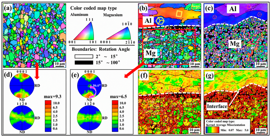
Discharge energy and stand-off distance jointly determine flyer acceleration, collision velocity, and collision angle in MPW [94,95,96]. Zhu et al. [13] used MPW to achieve solid-state joining of 1050 Al/AZ31 Mg lap joints and examined the effects of discharge energy and stand-off distance. The lap-shear force first increased and then decreased as discharge energy and stand-off distance increased. Under optimized conditions, the joint strength approached that of the Al base metal, with refined interfacial grains and no obvious IMCs. EBSD showed strong grain refinement near the interface and many twins on the Mg side. KAM maps also showed higher local strain concentration near the wavy interface than near the flat interface, as shown in Figure 10. A stable wavy interface formed more readily when Al was used as the flyer plate, while the Mg flyer configuration was more sensitive to the match between discharge energy and stand-off distance and had a higher risk of local impact damage [94].
MPW joints generally do not form a thick, continuous IMC layer immediately after welding, but heat treatment or high-temperature service can still trigger interfacial reactions. For example, Al12Mg17 begins to precipitate at the interface when the annealing temperature reaches 200 °C. At 250–300 °C, a brittle Al12Mg17/Al3Mg2 bilayer further forms at the interface [24,25]. These reaction layers increase local interfacial hardness but reduce the ability of the joint to accommodate deformation, so cracks are more likely to propagate along the IMCs/matrix interface.
Successful MPW requires sufficient electrical conductivity, resistance to impact-induced damage, and precise assembly control. For the Al/Mg system, oxidation and strong sensitivity to the assembly gap make it difficult to obtain a uniform and stable interface.

3.2. Fusion Welding

3.2.1. Laser Welding

Al/Mg laser welding provides short thermal cycles, localized heat input, and flexible energy-field control; however, its high energy density also narrows the process window. During irradiation, similar melting points promote local liquid contact, and limited solid solubility accelerates brittle Al–Mg IMC formation during cooling. Once these products form continuous interfacial layers or local reaction zones, deformation compatibility decreases and cracks tend to propagate along the brittle layer. Excessive heat input also induces Mg evaporation, vapor recoil, keyhole instability, spatter, and porosity. To address these coupled thermal and metallurgical problems, recent studies have mainly focused on reducing effective heat input, redistributing laser energy, and modifying the interfacial reaction pathway.
For ultrathin sheets, nanosecond pulsed laser welding reduces the heat-affected region through short pulse duration and discrete energy input. Wu et al. [21] showed that moderate power increased the effective bonded area and produced a tensile load of 76.5 N, whereas excessive power intensified Mg evaporation, porosity, and local collapse. Energy-density modulation further improves interface continuity; decreasing the line spacing in filled-circle scanning increases pulse overlap and raises the maximum tensile load to 121.5 N [97]. Pulsed irradiation induces periodic keyhole expansion and collapse under laser impact force and metal-vapor recoil pressure. Scanning speed alters the overlap and dwell time of adjacent pulse spots, thereby affecting pore formation and the interfacial reaction layer. Al3Mg2 and Al12Mg17 are still detected under optimized parameters [98].
Although pulsed input shortens the thermal cycle, further improvement requires spatial control of the molten pool and reaction zone. Beam shaping provides a more active way to redistribute heat input. Cui et al. [10] showed that transverse oscillation shifts the heat-source center along the interface and weakens local overheating, making the reaction zone less concentrated. Under repeated molten-pool disturbance, γ-Al12Mg17 and α-Mg + γ-Al12Mg17 eutectic structures tend to change from continuous blocky products into a wave-like interlocking region. With a Ti interlayer, 8-shaped oscillation reduces local energy overlap and improves interlayer heating continuity [11]. Infinite-shaped oscillation further modifies microscale precipitation through molten-pool stirring and heterogeneous-atom redistribution. The vortex-like flow redistributes Si, Fe, Cu, and Mn atoms in the Al/Mg mixed region, generating solute-rich regions that promote the formation of Mg2Si, Al13Fe4, and Al2Cu precipitates. Stirring also changes precipitate aggregation and may promote grain-boundary adsorption. The coherent Al2Cu/α-Al interface may contribute to precipitation strengthening and reduce the nucleation driving force for γ-Al12Mg17 [99].
In addition to controlling laser-energy distribution, transition layers provide another route to regulate the reaction sequence before direct Al–Mg interaction becomes dominant. Lv et al. [100] used a Ti interlayer as a high-melting-point barrier, guiding the interface toward Ti3Al and TiAl3 formation and producing a hybrid bonding mode involving Mg/Ti fusion welding and Ti/Al brazing. By contrast, Ni interlayers rely mainly on preferential Al–Ni/Mg–Ni reactions and thermal–diffusion barrier effects. In AA5182/ZEK100 laser welding/brazing, the Ni interlayer shifted the reaction products toward MgNi2, Mg2Ni, and AlNi, improving joint formation and mechanical performance [101].
The function of interlayers becomes broader in composite and multi-principal-element systems. Ti–Ni composite interlayers can form TiAl, Ti3Al, and Al3NiTi2, helping maintain interfacial continuity; once the interlayer is destroyed by excessive heat input, continuous Mg–Al IMCs may reappear [102]. Cu foil combined with 8-shaped oscillation divides the interface into Mg-side and Al-side molten pools, shifting the products toward Mg2Cu and Al2Cu [103]. CoCrFeNi powder forms an Al-rich AlxCoCrFeNi phase [104], while Ti/V/Cr mixed powders generate an in situ AlCrTiV solid solution. For these routes, the key limitation is still the continuity of the shielding layer, which is strongly affected by laser power and welding speed [105].
Hybrid laser–arc welding couples spatial heat-source distribution with filler spreading and interfacial reaction control. In non-axisymmetric laser–TIG welding, laser energy is mainly applied near the Al-side edge, while the TIG arc melts and spreads Zn filler. This heat-source partitioning allows welding speed to adjust reaction depth and MgZn2 distribution: a suitable speed produces finer MgZn2 in the Al/Zn solid solution, low speed causes microstructural coarsening, and excessive speed leads to local MgZn2 enrichment [106]. A similar principle is used in laser-offset TIG welding, where lateral displacement of the laser and arc lowers local energy density, improves filler spreading, and reduces Mg-side reaction depth [107]. Beyond heat-source arrangement, filler composition also changes the reaction pathway; moderate Al addition in Zn–Al filler reduces Mg dissolution and Mg–Zn reaction, whereas excessive Al promotes Mg32(Al,Zn)49 formation [108]. Combining a Ti interlayer with laser–arc hybrid welding allows beam oscillation to improve Ti-layer heating uniformity and transform localized overreaction into a more continuous Al–Mg–Ti reaction layer [109].
When interlayer regulation is combined with an auxiliary heat source, the process can simultaneously adjust filler spreading, interfacial wetting, and reaction-layer morphology. External fields and multi-beam designs shift the control target from interface chemistry to plasma behavior, keyhole stability, and bubble escape. Wang et al. [110] showed that magnetic-field-assisted laser welding with Ti foil can constrain plasma, modify molten-pool flow, and expand the Ti–Al reaction region, but an overly strong magnetic field may break Ti-foil continuity and restore direct Al–Mg reaction. Dual magnetic fields combined with ultrasound mainly suppress porosity by enhancing molten-pool flow, promoting bubble flotation, and delaying solidification [31]. IR–blue hybrid laser welding with V foil reduces peak energy density through a flat-top blue beam, improving Mg evaporation behavior and keyhole fluctuation while promoting V–Al reactions [111]. Dual-molten-pool laser welding uses a Ni interlayer to separate the Mg-side and Al-side pools, but fracture may still occur in the Al-side weld region because of hard Al–Ni reaction products [112].
While Table 4 focuses on interlayer materials and reaction regulation, process parameters remain equally important because they determine whether the designed reaction pathway can be maintained during actual welding. To clarify the process windows and performance levels reported for Al/Mg laser welding, Table 5 summarizes representative studies covering nanosecond pulsed laser welding, beam oscillation, interlayer-assisted laser welding, laser–arc hybrid welding, external-field assistance, and multi-wavelength laser welding. The selected studies are compared in terms of material combination, process route, optimized parameters, and the best reported mechanical performance. Because sheet thickness, lap configuration, interlayer design, and strength evaluation methods differ among these studies, the listed values are mainly used to compare process-regulation mechanisms and effective parameter ranges rather than to provide a direct ranking of joint strength.

3.2.2. Arc Welding

In Al/Mg arc welding, the main difficulty is the strong reaction between molten Al and Mg during a relatively long thermal cycle. Direct fusion readily produces continuous Al3Mg2 and Al12Mg17 layers, together with pores, cracks, and Mg evaporation. Most studies have therefore avoided simple direct fusion and instead used Zn-based interlayers, Zn-based filler metals, Ti addition, CMT-based low-heat-input processes, or magnetic-field-assisted molten-pool control.
In TIG welding, Zn is the most common transition element because it can promote Mg–Zn or Al–Zn reactions and reduce direct Mg–Al compound formation. Gao et al. [113] used a Zn interlayer in Mg/Al TIG lap welding and showed that the interlayer changed the reaction path. Liu et al. [114,115] further used Zn–Al–Ti filler metals for Mg/Al butt joints. In this system, the Zn-based filler formed a transition zone, while Ti addition promoted Al3Ti formation and grain refinement. TIG welding still has a narrow heat-input window. Insufficient heat input causes poor spreading and incomplete bonding, whereas excessive heat input accelerates Mg evaporation and Al/Mg interdiffusion.
MIG welding offers higher deposition efficiency, but stronger molten-pool mixing makes IMC control more difficult. Zhang et al. [116] used a Zn–Cd interlayer to obtain crack-free Al/Mg butt joints. The interlayer modified the interface and reduced direct Al/Mg reaction, but Cd raises clear environmental and safety concerns. This route is therefore more useful as a reference for reaction-pathway design than as a practical engineering solution.
Compared with conventional TIG and MIG welding, CMT is more suitable for Al/Mg joining because short-circuiting droplet transfer reduces heat input and spatter [117]. CMT, however, cannot fully prevent Al/Mg reactions. Cu-containing fillers can form Mg–Cu and Al–Cu products but may also create weak Mg–Cu-rich regions, whereas Al–Si fillers tend to reduce the thickness and continuity of the Al3Mg2 layer [118,119,120,121,122]. Variable-polarity CMT adjusts heat distribution by changing the electrode positive/negative ratio and thereby affects bead formation and reaction-layer growth [123].
In CMT welding, magnetic oscillation is useful when it changes both arc spreading and the morphology of the interfacial reaction layer. Liu et al. [124] joined AZ31B Mg and 6061 Al using longitudinal magnetic-field-assisted CMT. The magnetic field increased the effective arc-heating width from 11.3 mm to 16.3 mm, enlarged the weld width, reduced penetration depth and wetting angle, and markedly decreased porosity. At the interface, the conventional CMT joint formed a relatively thick layer of Al–Mg IMCs in region A, mainly consisting of Al3Mg2, Al12Mg17, and Mg2Si. After magnetic oscillation, the Al3Mg2 layer became thinner, the total interfacial layer thickness decreased from approximately 190 μm to approximately 140 μm, and Mg2Si became more dispersed. Under optimized conditions, the maximum lap-shear load reached 1411 N, about 30% higher than that of the conventional CMT joint. Fracture mainly occurred at the Al3Mg2 layer/weld interface or near the fusion line on the Al side.

3.2.3. Resistance Spot Welding

Resistance spot welding (RSW) is discussed here as a resistance-based spot joining process because bonding is governed by localized Joule heating, nugget formation, and interfacial reaction. For Al/Mg lap structures, RSW is attractive because it is fast and compatible with automotive spot-joining lines. Its main difficulty is asymmetric heat generation. The lower thermal conductivity of Mg tends to shift the nugget toward the Mg side, which promotes Mg evaporation, porosity, and rapid growth of IMCs [125,126].
Process parameters directly affect nugget size, molten-pool offset, and growth of IMCs in RSW. When welding current increases from 22 kA to 33 kA, heat generation and nugget size both increase. Joint strength reaches about 2.75 kN at 29 kA; further current increase may cause spattering, excessive Mg-side melting, and overgrowth of IMCs, all of which reduce strength [125]. For Al5754/AZ31B joints, a welding time of 300 ms and an electrode force of 800 N are considered suitable. Insufficient parameters produce a smaller nugget and more porosity, while excessive parameters can deform the Mg side. Because Mg has lower thermal conductivity, the nugget tends to shift toward the Mg side. Interfacial products such as Al12Mg17 and MgAl2O4 further affect heat dissipation and crack propagation [126].
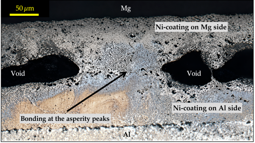
Interlayers can improve Al/Mg resistance spot welded joints by changing the direct Al/Mg reaction pathway. Their effectiveness depends on barrier capability, product type, and interfacial continuity. Zn layers [127] tend to form brittle Mg–Zn or Al–Zn phases, while galvanized-steel interlayers [128] physically separate the Al and Mg substrates by forming Al/steel and Mg/steel interfaces. Ni foils [129] and Ni coatings [130] can induce Al–Ni and Mg–Ni reactions and weaken the formation of Al–Mg IMCs, but excessive heat input may still cause Mg evaporation, pores, and cracks. Oheil et al. [131] pre-placed Ni coatings on AA6022 Al and AZ31B Mg by cold spraying for Al/Mg RSW. This changed the direct reaction interface into an Ni-containing interface and suppressed continuous brittle Al–Mg IMCs. As shown in Figure 11, the roughness and porosity of the cold-sprayed coatings may also generate interfacial voids and provide sites for Mg penetration and crack initiation.
Process modifications mainly weaken direct Al/Mg reactions by changing heat distribution or the load-bearing interface. Heat-compensated RSW can regulate interfacial heat distribution using a stainless-steel strip [127] or a graphite block [132], which modifies molten-pool composition, diffusion-layer structure, and continuous formation of IMCs. Joining elements or pre-designed structures can also change the current-concentration region and load-transfer path, reducing the dependence of joint strength on a continuous layer of IMCs [133]. Liu et al. [14] proposed a composite RSW process using prefabricated holes and Ni powder filling. A 4 mm hole was made in the Al sheet, allowing molten Mg to fill the hole under electrode pressure and form a mechanical interlocking structure. At the same time, Ni powder participated in the interfacial reactions and promoted Al–Ni and Mg–Ni phases, weakening direct Al/Mg reactions. Compared with direct RSW, this process increased the joint shear load from 2980 N to 5339.7 N, an improvement of about 79%.
RSW is better suited to localized lap joining than to joints requiring a wide metallurgical bonding area. Its performance is controlled by nugget position, Mg-side melting, continuity of IMCs, and the load-bearing contribution of interlayers or joining elements. Ni coating, heat compensation, and prefabricated-hole designs can reduce direct Al/Mg reaction, but they also introduce coating porosity, Mg penetration, and structural complexity.

3.3. Brazing

Brazing joins materials through wetting, spreading, and interfacial reactions of a liquid filler metal. It can reduce base-metal melting and thermal distortion, but joint performance still depends on filler-metal composition, reaction products, and continuity of IMCs. For Al/Mg systems, current brazing studies mainly focus on Sn–Zn filler design, surface coating modification, and ultrasonic-assisted wetting.
Zn-based filler metals are commonly used to weaken direct Al/Mg reactions and regulate the interface through Mg–Zn, Al–Zn, or Al–Mg–Zn products. Lai et al. [29] performed ultrasonic-assisted fluxless reactive brazing of Mg/Al dissimilar alloys using Zn–Al fillers. Al content strongly affected interfacial reactions and joint strength. As Al content increased, the continuous brittle MgZn2 layer was suppressed, and the interface changed into an (Al, Zn) eutectoid matrix containing dispersed MgZn2 particles. The Zn–15Al filler gave the maximum shear strength of 110.5 MPa. Zn-based interlayers or Zn–Al fillers can reduce joining temperature, promote transient liquid-phase formation, and regulate the interface through Mg–Zn, Al–Zn, or (Al, Zn)-related products [29,134]. Peng et al. [135] further used a Ni/Al/Zn multilayer interlayer for ultrasonic-assisted transient liquid-phase bonding. The different metallic layers regulated the reactions on the Mg and Al sides separately, increasing joint strength from 35.2 MPa to 95.3 MPa.
Sn–Zn filler metals have been widely studied for low-temperature Al/Mg brazing. They offer a low melting point, relatively low cost, and the ability of both Sn and Zn to participate in interfacial wetting and reactions. Wang et al. [136] found that the shear strength of AZ31B/6061 joints first increased and then decreased with increasing Zn content in Sn–xZn fillers. Sn–30Zn gave the best performance, with an average shear strength of 70.73 MPa. Fracture still occurred in the coarse blocky Mg2Sn phase at the center of the brazed seam. To reduce Mg2Sn-induced embrittlement, Liu et al. [137] pre-deposited a Ni coating on the Mg surface and used Sn–3.0Ag–0.5Cu filler for ultrasonic-assisted brazing. The joint shear strength reached 58.2 MPa at 280 °C, 80.7% higher than that of the uncoated joint. Later, Ni–Al2O3 nanocomposite coatings further suppressed blocky Mg2Sn formation and increased the maximum shear strength to 66.6–73.9 MPa [138,139].
Ultrasonic-assisted brazing uses cavitation and acoustic streaming to break surface oxide films, promote filler spreading, and modify the morphology and distribution of IMCs. Xu et al. [30] used Sn-based fillers for ultrasonic-assisted brazing of Al/Mg and found that this method could avoid Al–Mg IMCs, although a new Mg2Sn phase formed. Compared with Sn–3Cu, Sn–9Zn greatly reduced the thickness of the Mg2Sn layer. Lai et al. [140] compared different Sn–xZn fillers and reported that, in air, the highest average shear strength of 87.5 MPa was achieved using Sn–20Zn filler at 300 °C with 5 s of ultrasonic assistance. The fracture path lay entirely within the brazed seam. Microjets generated by ultrasonic cavitation can break layered or blocky Mg2Sn into finer and more dispersed particles. The Al(Zn) solid solution formed during cooling can also hinder microcrack propagation. Liu et al. [141] found that water cooling controlled the Mg2Sn thickness below 5 μm and shifted the fracture location from the IMC layer to the filler metal.
Brazing can reduce direct base-metal melting and suppress the continuous formation of IMCs, but its application remains limited by filler selection, Mg2Sn/MgZn2-induced embrittlement, and insufficient joint strength. Future work should develop low-melting-point filler systems, surface coatings, and interlayer designs that refine or replace brittle reaction products while improving joint strength and process stability.

3.4. Mechanical Joining: Riveting

Heat input during welding readily promotes the formation of IMCs and limits the application range of Al/Mg joints. Riveting, by contrast, is a low-heat-input cold-forming process that transfers load mainly through rivet flaring, sheet deformation, and mechanical interlocking. It avoids large-scale melting at the Al/Mg interface and suppresses continuous brittle IMCs [142]. Conventional riveting requires pre-drilled holes, which may cause local deformation or cracking in Al and Mg sheets with limited ductility. Self-piercing riveting (SPR) does not require pre-drilling, and is therefore more suitable for multi-material spot joining in automotive body structures [142]. The quality of Al/Mg SPR joints is affected by interlock size, Mg sheet position, sheet configuration, riveting parameters, die geometry, and local heating conditions [15,143]. Because Mg alloys have limited room-temperature ductility, the Mg sheet is usually placed on the upper side to reduce cracking at the bottom of the Mg sheet or near the rivet legs during rivet flaring and die compression [144].
Friction self-piercing riveting (F-SPR) is an improved process derived from conventional SPR. A high-speed rotating rivet introduces frictional heat, causing local thermal softening of the Al/Mg sheets, improving Mg alloy plastic flow, and combining mechanical interlocking with localized solid-state bonding [145]. Compared with conventional SPR, F-SPR can reduce riveting force, suppress Mg-sheet cracking, and improve the static load-bearing performance of joints [144,145]. Its effectiveness depends on a suitable thermo-mechanical input window. Stacking sequence [144], rivet rotational speed, punch speed [146], and rivet hardness and geometry [147] all affect heat input, rivet flaring behavior, and interfacial reactions.
Tubular dies require high coaxiality, and even slight misalignment may cause joint defects. To address this issue, Yang et al. [148] proposed an F-SPR process with a flat-bottom die for joining AA6061-T6 aluminum alloy and AZ31B magnesium alloy. A die distance of 1.0 mm avoided rivet upsetting and insufficient flaring, while a higher feed rate increased the interlock size and bottom thickness. At the joint interface, Al–Mg IMCs, a mechanically mixed layer, and Al–Fe atomic interdiffusion were observed. The Al alloy layer softened, the Mg alloy layer hardened, and the rivet hardness changed only slightly. As the feed rate increased from 2 mm/s to 8 mm/s, the failure mode changed from lower-sheet fracture to rivet pull-out and then to upper-sheet fracture. The peak load decreased, while energy absorption increased. Compared with protruding dies and flat-bottom cavity dies, the flat-bottom die still produced crack-free joints with better mechanical properties under a die offset of 1.5 mm.
Weld-assisted riveting and rivet–adhesive hybrid joining can further improve load transfer and sealing performance. In weld-assisted riveting, local metallurgical bonding works together with rivet locking, while rivet structure can regulate the fusion-zone position, IMC distribution, and pore formation [149]. In rivet–adhesive hybrid joining, the adhesive layer enlarges the load-transfer area and improves joint stiffness. However, its stability can be affected by adhesive aging, edge quality, residual stress, and corrosive-media ingress. Domitner et al. [150] showed that local fracture of the Mg sheet near the rivet hole affected both static strength and cyclic load-bearing behavior.
Corrosion and fatigue remain critical service-related concerns for Al/Mg riveted joints because galvanic coupling, lap gaps, adhesive-layer defects, rivet-induced deformation, and residual stresses can compromise long-term load transfer [151,152].
Accordingly, riveted Al/Mg joints should be evaluated together with interlock geometry, sheet damage, corrosion resistance, fatigue behavior, and the hybrid effect of adhesive bonding.

4. Comparison of Different Al/Mg Joining Technologies

Table 6 compares representative Al/Mg joining technologies from the perspective of engineering feasibility rather than direct mechanical ranking. FSW and LBW show relatively strong scalability for plate welding and automated localized joining, respectively, although FSW is constrained by tool accessibility and fixturing, while LBW requires strict control of Mg evaporation, porosity, and laser safety. USW, RSW, and SPR/F-SPR have short joining cycles and are more suitable for thin sheets, local lap joints, battery-tab structures, or automotive multi-material assembly. Their application is still affected by sonotrode size, electrode wear, rivet-induced damage, and corrosion around lap gaps. DB provides a more controllable interfacial reaction path, but the long holding time and vacuum/pressure requirements limit its production efficiency. EXW and MPW can achieve bonding within an extremely short time and reduce bulk thermal exposure, yet their wider use is restricted by safety requirements, assembly accuracy, and impact-condition control. Brazing and soldering offer low-temperature joining advantages, with performance strongly dependent on filler spreading, interfacial wetting, and the control of brittle Mg–Sn or Mg–Zn reaction products.
Al/Mg joining technologies vary markedly in heat input, plastic deformation, impact conditions, filler design, and interlayer strategy. Therefore, comparing different processes only by joint strength or average IMC thickness is insufficient. To provide a clearer basis for cross-process comparison, Table 7 summarizes an interfacial-reliability evaluation framework based on phase constitution, thickness distribution, continuity, defect coupling, and fracture-path relation.
This framework provides a basis for comparing Al/Mg joining technologies beyond IMC thickness. For example, a thin reaction layer may still weaken the joint if it is continuous or connected with pores and oxide inclusions. By contrast, discontinuous reaction products or interlocking morphologies may reduce crack-path continuity and improve load transfer. Therefore, the following process comparison considers both interfacial reliability and engineering feasibility.

5. Long-Term Service Performance

5.1. Corrosion Behavior

In general, service corrosion of Al/Mg joints is governed by the combined effects of macro-galvanic coupling, micro-galvanic coupling, and joining-induced interfacial heterogeneity. Compared with base metals, welded or mechanically joined regions usually contain mixed layers, reaction products, defects, and residual-stress fields. These features increase the tendency for localized corrosion, especially when an electrolyte penetrates reaction layers or defect-prone interfacial regions [16].
Specifically, in FSW joints, the stir zone is usually more corrosion-sensitive because severe plastic deformation produces lamellar or onion-ring Al/Mg structures, where Mg-rich regions, Al-rich regions, and reaction products coexist [153]. In another study, Abdul Khaliq et al. [154] reported a corrosion rate of 6.33 mm/year for AA6061/AZ61 FSW butt joints in 3.5 wt% NaCl. The relatively improved corrosion response was attributed to the use of AZ61 and the controlled distribution of the Al12Mg17 layer. Even so, corrosion products still accumulated in the stir zone and at the Al/SZ and SZ/Mg transition regions, indicating that local electrochemical heterogeneity was not fully eliminated.
By contrast, fusion-welded and hybrid-welded joints show more complex corrosion paths. Interlayers can suppress direct Al/Mg reactions, but the newly formed phases may introduce additional galvanic couples. In Ti-interlayer-assisted laser–arc hybrid welded joints, Al–Ti phases reduced direct Al/Mg reaction, while their higher Volta potential promoted local coupling with the adjacent Al matrix and the Al/Mg interdiffusion layer. The 6061/WJ transition region became vulnerable to selective corrosion because of compositional gradients and secondary phases [32].
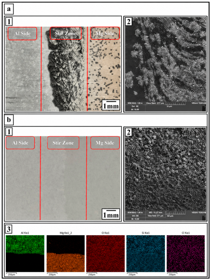
In addition, surface protection can reduce corrosion sensitivity, although improvements in mechanical performance and corrosion resistance do not necessarily occur simultaneously. Safari et al. [155] observed severe corrosion in the stir zone of uncoated AA5052/AZ31 FSW joints after immersion in 3.5 wt% NaCl solution. As shown in Figure 12, the PEO coating effectively suppressed corrosion product accumulation and reduced the corrosion current density. In a related casting-based Al/Mg bimetal system, a Ni–Cu composite interlayer reduced the interfacial thickness from approximately 1400 μm to about 40 μm and improved shear strength, while its improvement in overall corrosion resistance remained limited [156].

5.2. Fatigue Behavior

Under cyclic loading, fatigue failure of Al/Mg joints is controlled by reaction-layer continuity, local bending, residual stress, and the load-transfer path around the bonded or mechanically locked region. In spot-welded joints, cyclic loading often causes a transition from interfacial fracture at high loads to nugget-edge or transverse-through-thickness (TTT) cracking at lower loads.
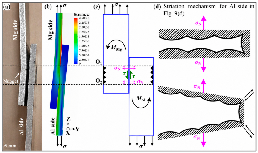
Specifically, USW fatigue studies show that welding energy has a dual effect. Macwan and Chen [157] found that increasing energy thickened the α-Mg + Al12Mg17 diffusion layer in ZEK100/5754 joints; the 500 J joint showed longer fatigue life than the 1000 J joint under higher cyclic loads, while both became comparable under lower loads. Similarly, in clad-Al systems, the Al cladding layer improved interfacial deformation compatibility and promoted fishhook-like or wave-like interlocking, which benefited tensile-shear strength and fatigue life [71]. However, excessive energy still increased the thickness of the brittle reaction layer and promoted TTT failure. Finite element analysis further showed that bending at the weld nugget edge generated local opening stress, producing Mode I fatigue crack features in the soft Al cladding layer [17].
Similar evidence is provided by FSLW, RSW, and SPR, where fatigue life is affected by IMC distribution, local stress concentration, weld defects, and load-transfer path. Zhang et al. [158] reported that AZ31B/Al6061 FSW joints exhibited two fatigue fracture modes under different loading levels, with incomplete-fusion defects and mixed brittle–ductile fracture features. Notch-stress and local stress–strain finite element models predicted fatigue life with most errors within a factor of three, and the Manson–Coffin model showed better suitability for the tested data. In RSW joints, a Sn-coated steel interlayer suppressed direct Al/Mg reaction and changed the failure path from brittle interfacial fracture to load-dependent mixed modes [159]. For SPR joints, fatigue behavior is mainly affected by interlock geometry and residual stress; compressive residual stresses around the rivet can reduce the effective stress amplitude and extend fatigue life [152].

5.3. Thermal Exposure

Thermal exposure and thermal cycling are also important for Al/Mg joints because interfacial reaction layers may continue to grow after joining. This issue is particularly evident in MPW and EXW joints. For MPW joints, thick and continuous IMC layers are usually not formed immediately after welding, but annealing at about 200 °C can induce Al12Mg17 precipitation, and a brittle Al12Mg17/Al3Mg2 bilayer may further form at 250–300 °C [24,25]. For EXW joints, post-weld annealing, rolling, and hot rolling can release residual stress and improve formability, but they may also promote interfacial diffusion, thicken IMC layers, or transform the reaction layer into a γ-Al12Mg17/β-Al3Mg2 bilayer [89,90,91,92,93]. Repeated thermal loading may further redistribute residual stress and increase cracking susceptibility near brittle reaction layers, pores, or oxide-rich interfacial regions [19,152]. Compared with corrosion and fatigue, direct creep studies on Al/Mg joints remain limited; therefore, the relationship among creep deformation, IMC growth, and interfacial fracture still needs systematic investigation.

6. Numerical Simulation and Data-Driven Prediction

Numerical simulation has become important for Al/Mg dissimilar-metal joining because transient thermal behavior, material flow, keyhole fluctuation, residual stress, and interfacial reactions are difficult to measure directly. Multiphase-field, CFD, FEM, MD, and data-driven models have been used to connect process parameters with interfacial reactions, defects, and joint performance, although their outputs still require validation through microstructural characterization and mechanical testing.

6.1. Multiphase-Field Modeling

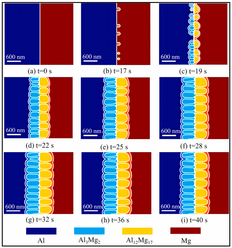
Multiphase-field modeling is mainly used to predict the nucleation, growth, and spatial distribution of Al–Mg IMCs. Compared with empirical diffusion-distance models, it can incorporate thermal history and local composition into phase-field variables and describe the evolution of Al12Mg17 and Al3Mg2 more directly. Zhao et al. [160] developed a multiphase-field model for Al/Mg FSW joints and obtained simulated IMC thicknesses consistent with experimental measurements. In Figure 13, the simulated IMC morphology shows how different reaction products nucleate and grow during interfacial evolution.
The value of multiphase-field modeling lies in its ability to relate phase formation to local thermal–composition conditions, rather than treating the reaction layer as a uniform diffusion product. This is particularly useful for Al/Mg joints, where lamellar mixing, fragmented reaction layers, and locally discontinuous bonding are often observed. However, the prediction accuracy remains sensitive to boundary conditions, diffusion coefficients, phase-interface mobility, and deformation-induced mixing parameters.
At a larger process scale, the main concern shifts from phase growth itself to heat transfer, molten-pool motion, keyhole fluctuation, and material redistribution. These issues are usually treated using CFD-based models.

6.2. CFD Modeling

CFD models are mainly used to analyze heat transfer, molten-pool flow, keyhole behavior, and elemental transport in Al/Mg fusion welding. In laser welding, Marangoni flow, recoil pressure, and keyhole fluctuation affect local Al/Mg redistribution and the predicted formation regions of Al3Mg2 and Al12Mg17. One laser-welding study related simulated mass-fraction distribution to the formation of these IMCs in the molten zone, where the high-hardness transition region was associated with cracking susceptibility [161].
For Ti-interlayer-assisted laser welding, the simulated and experimental weld cross sections showed maximum errors of 10.1% for weld width and 8.5% for penetration depth, suggesting that CFD can support process-window design for interlayer-regulated laser welding [162]. In oscillating laser welding, a 3D transient fluid–solid coupled model was further used to analyze bubble behavior; infinite oscillation generated a high-gradient velocity zone along the keyhole axis and reduced porosity to about 0.4%, compared with 4.33% under circular oscillation [163].
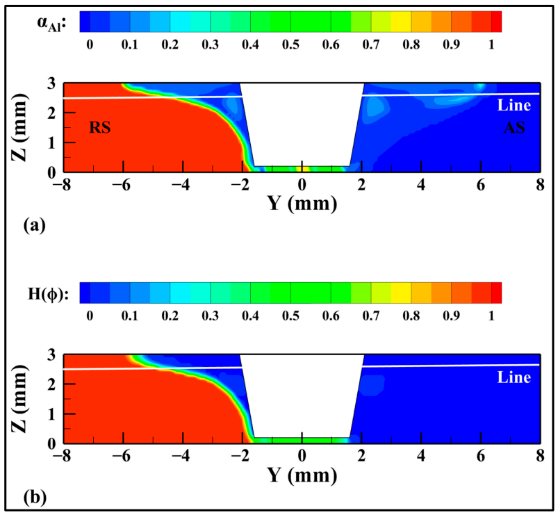
For solid-state FSW, the plasticized zone is often treated as a non-Newtonian viscoplastic flow. Earlier CFD work analyzed mass transfer and material mixing during Al/Mg FSW, showing that tool-induced flow strongly affects interfacial morphology and local material redistribution [164]. More recently, Zhang et al. [165] used the coupled level set and volume of fluid method to improve Al/Mg interface tracking. In Figure 14, the CLSVOF result gives a clearer two-phase interface than the VOF result and better captures material redistribution near the tool.
While CFD focuses on flow and material redistribution, stress evolution and deformation history require a different modeling route. FEM is therefore more suitable for analyzing residual stress, transient electromagnetic loading, and macroscopic deformation.

6.3. Finite Element Modeling

Finite element modeling is mainly used to evaluate temperature fields, residual stresses, plastic deformation, and their influence on joint integrity. In Al/Mg FSW and ultrasonic-assisted FSW, coupled process simulation combined with residual-stress measurements showed that ultrasonic vibration can expand the compressive stress region, reduce tensile residual stress, promote material mixing, and thin the IMC layer [166]. This links auxiliary-field input with both stress redistribution and interfacial microstructure evolution.
For MPW, electromagnetic–mechanical models describe capacitor discharge, transient electromagnetic force, flyer-plate deformation, collision-zone formation, and wavy-interface evolution [167,168]. These simulations are useful for clarifying impact conditions and bonding-zone morphology, especially because the actual collision process occurs within an extremely short time. Further coupling with temperature rise, local melting, interfacial damage, and post-weld IMC growth is still needed.

6.4. Molecular Dynamics Simulation

At the atomic scale, MD simulation provides insight into interfacial bonding, atomic mixing, local deformation, temperature evolution, and stress distribution. Nguyen et al. [169] simulated the Al–Mg FSW process and showed that travel speed, rotation speed, and tool-pin geometry strongly affect atomic mixing and local disorder. Al atoms mixed more readily into the Mg plate, whereas Mg atoms penetrated deeper into the weld region. Higher travel speed increased atomic strain, local temperature, and amorphous fraction, while the strongest mechanical mixing occurred at a rotation speed of 12 rad/ps [169]. Because stable IMC growth occurs over longer diffusion time scales than conventional MD can capture, this work should be interpreted mainly as evidence for early-stage atomic mixing and shear-induced interfacial disorder during Al/Mg FSW.
Related MD studies on ultrasonic metal welding indicate that crystal orientation and sliding velocity affect interfacial diffusion, tensile strength, and frictional heat generation [170]. Since these results were obtained mainly from Al/Al systems, they should be used as methodological evidence for ultrasonic joining simulations rather than direct proof for Al/Mg ultrasonic welding. Direct MD evidence for Al/Mg ultrasonic welding remains limited, especially for cases involving oxide films, IMC nucleation, multi-grain interfaces, and longer thermo-mechanical cycles.
These physics-based models improve the interpretation of joining mechanisms, but they are still limited by computational cost and simplified assumptions. Data-driven methods have therefore been introduced to build faster process–response mappings from the experimental and simulation datasets.

6.5. Data-Driven Prediction and Parameter Optimization

Data-driven prediction has been increasingly introduced into Al/Mg dissimilar-metal joining to establish process–response relationships between welding parameters and joint performance. Compared with conventional empirical fitting, these approaches can integrate experimental data, numerical simulation outputs, and statistical or machine learning algorithms to predict thermal, mechanical, and strength-related responses more efficiently.
Zhai et al. [41] combined experiments, machine learning, and numerical analysis to relate process parameters, heat–mass transfer behavior, and joint strength in Mg/Al friction stir lap welding. In their machine-learning workflow, the process inputs were collected and normalized before feature processing, model training, and performance evaluation using RMSE and R2. The comparison of multiple regression models using the same dataset provided a quantitative means of examining the relationship between process parameters and joint strength.
For Al/Mg laser welding, Efa et al. [171,172,173] combined finite-element simulation with CCD/RSM, genetic algorithms, multi-objective optimization, and artificial neural networks to predict thermal–mechanical responses. In the multi-objective LBW study, the optimized parameter combination was approximately 4011 W laser power, 30 mm/s welding velocity, 0.8 mm spot size, and 12 segments, with predicted peak temperature and residual stress ranges of 1148.2–1158.0 °C and 1393.3–1534.4 MPa, respectively. Simulation, response surface methodology (RSM), and artificial neural network (ANN) predictions showed similar trends in peak temperature and stress responses, indicating that ANN-assisted models can approximate finite-element outputs under different parameter combinations [173].
Model-based prediction has also been extended to Al/Mg friction stir welding. Yang et al. [174] used a thermo-mechanical-flow fully coupled model to analyze material flow and interface evolution during dissimilar FSW of AA6061 Al and AZ31B Mg. A later study developed a constitutive model for Al/Mg mixtures and incorporated the high-temperature softening behavior of the interfacial layer into a CFD framework [175]. These studies complement data-driven approaches by providing physics-based descriptions of mixed-material deformation, interfacial softening, and material redistribution, which are important for more reliable parameter prediction in Al/Mg FSW.

7. Conclusions and Outlook

This review summarizes recent advances in Al/Mg dissimilar-metal joining, with emphasis on interfacial reactions, defect formation, mechanical performance, service reliability, and simulation-assisted understanding. The main conclusions and future directions are as follows.
(1) The primary difficulty in Al/Mg joining is the formation of brittle Al–Mg intermetallic compounds, especially Al3Mg2 and Al12Mg17. Their influence on joint reliability depends not only on thickness, but also on phase type, continuity, spatial distribution, local enrichment, and participation in the fracture path.
(2) Solid-state and high-speed impact processes, including FSW, USW, diffusion bonding, EXW, and MPW, are effective in reducing continuous Al–Mg reaction layers by limiting thermal exposure or promoting plastic contact. However, their applicability is still restricted by material flow, oxide disruption, assembly accuracy, joint geometry, and post-weld thermal stability.
(3) Fusion-based processes provide higher flexibility and automation potential, but they require stricter control of local melting, Mg evaporation, keyhole instability, porosity, and rapid IMC growth. Beam oscillation, pulsed input, hybrid heat sources, external fields, and interlayers can improve joint formation when heat input and reaction-layer continuity are properly controlled.
(4) Interlayer design is an important strategy for changing the Al/Mg reaction pathway. Ti, Ni, Cu, Zn, Sn, Ag, V, and multi-principal-element interlayers can promote alternative Al–X or Mg–X reactions and suppress continuous Al–Mg IMCs, but their cost, manufacturing complexity, phase stability, corrosion behavior, and long-term reliability still require systematic evaluation.
(5) Future studies should strengthen standardized testing and reporting protocols for Al/Mg joints. Joint geometry, sheet thickness, overlap length, weld width, bonded area, loading direction, and original fracture load should be reported together with normalized values when possible, such as load per unit width or strength based on bonded area. Interfacial characterization should include IMC phase type, average and local maximum thickness, continuity, spatial distribution, and fracture-path relation. For service assessment, corrosion tests should specify electrolyte, immersion time, polarization or EIS conditions, and post-corrosion morphology, while fatigue tests should report load ratio, frequency, maximum load, S–N data, and failure mode. These criteria would improve the comparability of different joining technologies and provide clearer guidance for engineering process selection.

Author Contributions

T.Q.: conceptualization, literature investigation, data curation, visualization, writing—original draft, and writing—review and editing. M.N.B.O.Z.: conceptualization, methodology, supervision, project administration, and writing—review and editing. All authors have read and agreed to the published version of the manuscript.

Funding

This research was supported by the Intelligent Manufacturing Engineering Laboratory of Shandong Huayu University of Technology (PT2025KJS002).

Data Availability Statement

No new data were created or analyzed in this study.

Conflicts of Interest

The authors declare that they have no known competing financial interests or personal relationships that could have appeared to influence the work reported in this paper.

References

  1. Dada, M.; Popoola, P. Recent advances in joining technologies of aluminum alloys: A review. Discov. Mater. 2024, 4, 86. [Google Scholar] [CrossRef] [Scilit]
  2. Liu, L.; Ren, D.; Liu, F. A Review of Dissimilar Welding Techniques for Magnesium Alloys to Aluminum Alloys. Materials 2014, 7, 3735–3757. [Google Scholar] [CrossRef] [Scilit] [PubMed]
  3. Ahmed, M.M.Z.; Seleman, M.M.E.S.; Fydrych, D.; Çam, G. Review on friction stir welding of dissimilar magnesium and aluminum alloys: Scientometric analysis and strategies for achieving high-quality joints. J. Magnes. Alloys 2023, 11, 4082–4127. [Google Scholar] [CrossRef] [Scilit]
  4. Chen, H.; Zhu, Z.Q.; Zhu, Y.M.; Sun, L.; Guo, Y.K. Solid-State Welding of Aluminum to Magnesium Alloys: A Review. Metals 2023, 13, 1410. [Google Scholar] [CrossRef] [Scilit]
  5. Xu, Y.; Ke, L.M.; Mao, Y.Q.; Yang, P.; Niu, P.L. Friction stir welding of aluminium to magnesium: A critical review. Mater. Sci. Technol. 2022, 38, 517–534. [Google Scholar] [CrossRef] [Scilit]
  6. Mehdi, H.; Bhati, S.S.; Mouria, P.K.; Mishra, S. A comprehensive review of progressive developments and challenges in dissimilar welding of aluminum and magnesium alloy by friction stir welding. J. Adhes. Sci. Technol. 2025, 39, 1979–2026. [Google Scholar] [CrossRef] [Scilit]
  7. Zhang, J.; Li, H.; Wu, S.Y. Research progress of aluminum and magnesium ultrasonic welding. China Weld. 2025, 34, 74–84. [Google Scholar] [CrossRef]
  8. Baqer, Y.M.; Ramesh, S.; Yusof, F.; Manladan, S.M. Challenges and advances in laser welding of dissimilar light alloys: Al/Mg, Al/Ti, and Mg/Ti alloys. Int. J. Adv. Manuf. Technol. 2018, 95, 4353–4369. [Google Scholar] [CrossRef] [Scilit]
  9. Shah, L.H.; Gerlich, A.; Zhou, Y. Design guideline for intermetallic compound mitigation in Al-Mg dissimilar welding through addition of interlayer. Int. J. Adv. Manuf. Technol. 2018, 94, 2667–2678. [Google Scholar] [CrossRef] [Scilit]
  10. Cui, M.F.; Zheng, Z.T.; Du, P.; Cheng, Z.C. Experimental and numerical simulation study of magnesium/aluminium dissimilar metal swing laser welding. Mater. Today Commun. 2024, 39, 108813. [Google Scholar] [CrossRef] [Scilit]
  11. Meng, Y.F.; Fu, J.W.; Gong, M.C.; Zhang, S.; Gao, M.; Chen, H. Laser dissimilar welding of Al/Mg lap-joint with Ti interlayer through optimized 8-shaped beam oscillation. Opt. Laser Technol. 2023, 162, 109304. [Google Scholar] [CrossRef] [Scilit]
  12. Chang, L.; Yu, D.; Zheng, Z.T.; Zhang, Y.; Cui, M.F.; Du, P. Study on process, microstructure and mechanical properties of 6061/AZ31 dissimilar metal joining with direct contact reaction brazing. J. Adhes. Sci. Technol. 2024, 38, 2621–2646. [Google Scholar] [CrossRef] [Scilit]
  13. Zhu, C.C.; Xu, S.W.; Gao, W.L.; Meng, Y.F.; Lin, S.; Dai, L. Microstructure characteristics and mechanical properties of Al/Mg joints manufactured by magnetic pulse welding. J. Magnes. Alloys 2023, 11, 2366–2375. [Google Scholar] [CrossRef] [Scilit]
  14. Liu, S.; Fang, Y.S.; Fu, J.W.; Xia, C.S.; Hu, X.B.; Long, W. The effect of a novel prefabricated hole-filling powder process on microstructures and mechanical properties of Al/Mg resistance spot welded joints. Mater. Today Commun. 2025, 46, 112682. [Google Scholar] [CrossRef] [Scilit]
  15. Liu, B.; Zhang, K.; Zhou, H.; Zhu, R.H.; Song, J.F.; Ren, W.; Yang, Y.; Zeng, Y.L. Forming mechanism and strength evaluation on self-piercing riveting of aluminum alloy and die-casting magnesium. Arch. Civ. Mech. Eng. 2025, 25, 255. [Google Scholar] [CrossRef] [Scilit]
  16. Safari, S.; Nouripour, M.H.; Ghorbani, M.; Safari, H. The effect of FSW parameters on the macro/micro-galvanic corrosion of the dissimilar joint between AZ31 and AA5052. Mater. Chem. Phys. 2023, 305, 127945. [Google Scholar] [CrossRef] [Scilit]
  17. Dash, S.S.; Fernandes, R.C.; Shang, X.; Zou, Y.; Peng, H.; Jiang, X.Q.; Fang, X.F.; Ma, N.; Li, D.Y.; Chen, D.L. Fatigue and deformation mechanisms of ultrasonic spot-welded dissimilar joints of a magnesium alloy to a clad aluminum alloy. J. Magnes. Alloys 2025, 13, 1939–1952. [Google Scholar] [CrossRef] [Scilit]
  18. Jiang, X.Q.; Liu, Y.Y.; Yuan, T.; Chen, S.J.; Wang, L.; Jiang, W. Enhanced mechanical properties of dissimilar Al and Mg alloys fabricated by pulse current assisted friction stir welding. J. Manuf. Process. 2022, 76, 123–137. [Google Scholar] [CrossRef] [Scilit]
  19. Chen, W.; Wang, W.X.; Liu, Z.P.; Zhai, X.B.; Bian, G.F.; Zhang, T.; Dong, P. Improvement in tensile strength of Mg/Al alloy dissimilar friction stir welding joints by reducing intermetallic compounds. J. Alloys Compd. 2021, 861, 157942. [Google Scholar] [CrossRef] [Scilit]
  20. He, C.S.; Qiu, C.P.; Zhang, Z.Q.; Wei, J.X.; Zhang, H.; Tian, N.; Qin, G.W. Microstructure and mechanical properties of 6061 Al/AZ31 Mg joints friction stir lap welded by a tool with variable-pitch thread pin. Metals 2021, 11, 34. [Google Scholar] [CrossRef] [Scilit]
  21. Wu, Z.; Wu, X.L.; Zhang, Y.; Liu, Y.L.; Zhang, X.L.; Yang, C.M. Effect of nanosecond pulse laser power on welding interface and mechanical properties of AZ31B Mg/6061 Al. Opt. Laser Technol. 2024, 175, 110848. [Google Scholar] [CrossRef] [Scilit]
  22. Zhao, J.J.; Wu, C.S.; Shi, L.; Su, H. Evolution of microstructures and intermetallic compounds at bonding interface in friction stir welding of dissimilar Al/Mg alloys with/without ultrasonic assistance. J. Mater. Sci. Technol. 2023, 139, 31–46. [Google Scholar] [CrossRef] [Scilit]
  23. Chen, Z.W.; Shi, L.; Su, H.; Wu, C.S. Numerical and experimental investigation on intermetallic compounds formation in ultrasonic vibration enhanced friction stir welding of dissimilar Al/Mg alloys. J. Alloys Compd. 2024, 977, 173426. [Google Scholar] [CrossRef] [Scilit]
  24. Zhu, C.C.; Sun, L.Q.; Gao, W.L.; Li, G.Y.; Cui, J.J. The effect of temperature on microstructure and mechanical properties of Al/Mg lap joints manufactured by magnetic pulse welding. J. Mater. Res. Technol. 2019, 8, 3270–3280. [Google Scholar] [CrossRef] [Scilit]
  25. Li, Y.; Yang, D.Z.; Yang, W.Y.; Wu, Z.S.; Liu, C.R. Effect of annealing temperature on microstructure and properties of Al/Mg magnetic pulse welding joints. Materials 2022, 15, 5519. [Google Scholar] [CrossRef] [Scilit] [PubMed]
  26. Gu, X.Y.; Sui, C.L.; Liu, J.; Li, D.L.; Meng, Z.Y.; Zhu, K.X. Microstructure and mechanical properties of Mg/Al joints welded by ultrasonic spot welding with Zn interlayer. Mater. Des. 2019, 181, 108103. [Google Scholar] [CrossRef] [Scilit]
  27. Mihara-Narita, M.; Asai, K.; Sato, H.; Watanabe, Y.; Nakatsugawa, I.; Saito, N.; Chino, Y. Dissimilar welding of magnesium alloys and aluminum alloys by explosive welding. Materials 2025, 18, 1013. [Google Scholar] [CrossRef] [Scilit] [PubMed]
  28. Yan, Y.B.; Zhang, Z.W.; Shen, W.; Wang, J.H.; Zhang, L.K.; Chin, B.A. Microstructure and properties of magnesium AZ31B–aluminum 7075 explosively welded composite plate. Mater. Sci. Eng. A 2010, 527, 2241–2245. [Google Scholar] [CrossRef] [Scilit]
  29. Lai, Z.W.; Pan, C.; Du, H.Q.; Chen, X.G.; Xie, R.S.; Liu, L.; Long, W.M.; Zou, G.S. Ultrasonic-assisted fluxless reactive bonding of Mg/Al dissimilar alloy using Zn–Al solder in air. Sci. Technol. Weld. Join. 2018, 23, 19–27. [Google Scholar] [CrossRef] [Scilit]
  30. Xu, Z.W.; Li, Z.W.; Li, J.Q.; Ma, Z.P.; Yan, J.C. Control Al/Mg intermetallic compound formation during ultrasonic-assisted soldering Mg to Al. Ultrason. Sonochem. 2018, 46, 79–88. [Google Scholar] [CrossRef] [Scilit] [PubMed]
  31. Fei, X.J.; Lan, J. Pore suppression study on Mg/Al joint in laser welding by dual magnetic fields and ultrasound wave. Sci. Rep. 2026, 16, 16065. [Google Scholar] [CrossRef] [Scilit] [PubMed]
  32. Zhuang, J.; Gong, M.; Yang, J.; Liao, B.; Yu, Z.; Zhou, S.; Gao, M. Insight into the alternative galvanic corrosion behaviors of the laser-arc hybrid welded magnesium/aluminum dissimilar joints. Corros. Sci. 2025, 246, 112763. [Google Scholar] [CrossRef] [Scilit]
  33. Fu, B.L.; Qin, G.L.; Li, F.; Meng, X.M.; Zhang, J.Z.; Wu, C.S. Friction stir welding process of dissimilar metals of 6061-T6 aluminum alloy to AZ31B magnesium alloy. J. Mater. Process. Technol. 2015, 218, 38–47. [Google Scholar] [CrossRef] [Scilit]
  34. Venkateswaran, P.; Reynolds, A.P. Factors affecting the properties of friction stir welds between aluminum and magnesium alloys. Mater. Sci. Eng. A 2012, 545, 26–37. [Google Scholar] [CrossRef] [Scilit]
  35. Torabi, K.; Beygi, R.; Eisaabadi Bozchaloei, G.; da Silva, L.F.M. The effect of tool rotation speed on the formation of eutectic structure during friction stir welding of aluminum to magnesium. Appl. Sci. 2023, 13, 7133. [Google Scholar] [CrossRef] [Scilit]
  36. Bandi, A.; Bakshi, S.R. Effect of pin length and rotation speed on the microstructure and mechanical properties of friction stir welded lap joints of AZ31B-H24 Mg alloy and AA6061-T6 Al alloy. Metall. Mater. Trans. A 2020, 51, 6269–6282. [Google Scholar] [CrossRef] [Scilit]
  37. Zhai, M.; Wu, C.S.; Shi, L. Influence of tool pin length and dissimilar material configuration on friction stir lap welding of Al and Mg alloys. Int. J. Adv. Manuf. Technol. 2022, 122, 1567–1582. [Google Scholar] [CrossRef] [Scilit]
  38. Mao, Y.Q.; Yang, P.; Zhang, W.Y.; Li, N.; Nie, H.; Lin, D.Y.; Ke, L.M. Improving tensile-shear properties of friction stir lap welded dissimilar Al/Mg joints by eliminating hook defect and controlling interfacial reaction. Chin. J. Aeronaut. 2023, 36, 257–267. [Google Scholar] [CrossRef] [Scilit]
  39. Mehdi, H.; Jain, S.; Nait Salah, A.; Singh, A.P.; Chawla, S. Effect of friction stir welding parameters on microstructure and mechanical properties of the dissimilar alloys of AZ91D and AA7075. Proc. Inst. Mech. Eng. Part E J. Process Mech. Eng. 2025, 239, 2050–2063. [Google Scholar] [CrossRef] [Scilit]
  40. Ghiasvand, A.; Ranjbarnodeh, E.; Mirsalehi, S.E. The microstructure and mechanical properties of single-pass and double-pass lap joint of Al 5754H-11 and Mg AZ31-O alloys by friction stir welding. J. Mater. Res. Technol. 2023, 23, 6023–6038. [Google Scholar] [CrossRef] [Scilit]
  41. Zhai, M.; Yin, J.L.; Yang, C.L.; Wu, C.S.; Song, H.T.; Zhao, W.Z.; Shi, L.; Qiao, J.N. Investigating the relationship of process parameter, heat-mass transfer and joint strength in Mg/Al friction stir lap welding via experiments, machine learning and numerical analysis. Int. J. Heat Mass Transf. 2025, 247, 127143. [Google Scholar] [CrossRef] [Scilit]
  42. Peng, P.; Wang, W.; Zhang, T.; Liu, Q.; Guan, X.H.; Qiao, K.; Cai, J.; Wang, K.S. Effects of interlayer metal on microstructures and mechanical properties of friction stir lap welded dissimilar joints of magnesium and aluminum alloys. J. Mater. Process. Technol. 2022, 299, 117362. [Google Scholar] [CrossRef] [Scilit]
  43. Kumar, S.; Wu, C.S. Eliminating intermetallic compounds via Ni interlayer during friction stir welding of dissimilar Mg/Al alloys. J. Mater. Res. Technol. 2021, 15, 4353–4369. [Google Scholar] [CrossRef] [Scilit]
  44. Liu, J.L.; Niu, S.Y.; Ren, R.; Ji, S.D.; Wang, L.; Lv, Z. Improving joint morphologies and tensile strength of Al/Mg dissimilar alloys friction stir lap welding by changing Zn interlayer thickness. Acta Metall. Sin. 2019, 32, 1385–1395. [Google Scholar] [CrossRef] [Scilit]
  45. Kumar, M.; Das, A.; Ballav, R. Influence of the Zn interlayer on the mechanical strength, corrosion and microstructural behavior of friction stir-welded 6061-T6 aluminium alloy and AZ61 magnesium alloy dissimilar joints. Mater. Today Commun. 2023, 35, 105509. [Google Scholar] [CrossRef] [Scilit]
  46. Zheng, B.; Zhao, L.; Lv, Q.Q.; Wan, G.; Cai, D.; Dong, S.J.; Hu, X.B. Effect of Sn interlayer on mechanical properties and microstructure in Al/Mg friction stir lap welding with different rotational speeds. Mater. Res. Express 2020, 7, 076504. [Google Scholar] [CrossRef] [Scilit]
  47. Zhou, B.F.; Feng, H.A.; Leng, Z.X.; Zhang, H.X. Effect of microstructure and mechanical properties of Al/Mg dissimilar alloy with Pb interlayer by friction stir welding. J. Sci. Adv. Mater. Devices 2025, 10, 100845. [Google Scholar] [CrossRef] [Scilit]
  48. Dewangan, S.K.; Tripathi, M.K.; Manoj, M.K. Material flow behavior and mechanical properties of dissimilar friction stir welded Al 7075 and Mg AZ31 alloys using Cd interlayer. Met. Mater. Int. 2022, 28, 1169–1183. [Google Scholar] [CrossRef] [Scilit]
  49. Zheng, Y.; Pan, X.M.; Ma, Y.L.; Liu, S.M.; Zang, L.B.; Chen, Y. Microstructure and corrosion behavior of friction stir-welded 6061 Al/AZ31 Mg joints with a Zr interlayer. Materials 2019, 12, 1115. [Google Scholar] [CrossRef] [Scilit] [PubMed]
  50. Abdollahzadeh, A.; Shokuhfar, A.; Cabrera, J.M.; Zhilyaev, A.P.; Omidvar, H. In-situ nanocomposite in friction stir welding of 6061-T6 aluminum alloy to AZ31 magnesium alloy. J. Mater. Process. Technol. 2019, 263, 296–307. [Google Scholar] [CrossRef] [Scilit]
  51. Sharifi Asl, N.; Mirsalehi, S.E.; Dehghani, K. Effect of TiO2 nanoparticles addition on microstructure and mechanical properties of dissimilar friction stir welded AA6063-T4 aluminum alloy and AZ31B-O magnesium alloy. J. Manuf. Process. 2019, 38, 338–354. [Google Scholar] [CrossRef] [Scilit]
  52. Bagheri Vanani, B.; Abdollahzadeh, A. Fabrication of reinforced Al–Mg composite by TiC particles via FSW: Microstructure and tribology study. J. Mater. Res. Technol. 2024, 30, 6787–6801. [Google Scholar] [CrossRef] [Scilit]
  53. Kumar, S.; Wu, C.S.; Zhen, S.; Ding, W. Effect of ultrasonic vibration on welding load, macrostructure, and mechanical properties of Al/Mg alloy joints fabricated by friction stir lap welding. Int. J. Adv. Manuf. Technol. 2019, 100, 1787–1799. [Google Scholar] [CrossRef] [Scilit]
  54. Kumar, S.; Wu, C.S.; Shi, L. Intermetallic diminution during friction stir welding of dissimilar Al/Mg alloys in lap configuration via ultrasonic assistance. Metall. Mater. Trans. A 2020, 51, 5725–5742. [Google Scholar] [CrossRef] [Scilit]
  55. Zhang, G.L.; Gao, J.Q.; Wu, C.S. Revealing the acoustic effects on heat transfer and material flow in ultrasonic assisted friction stir welding of dissimilar Al/Mg alloys. J. Mater. Res. Technol. 2023, 26, 1882–1902. [Google Scholar] [CrossRef] [Scilit]
  56. Zhai, M.; Shi, L.; Wu, C.S. Elucidating the process mechanism in Mg-to-Al friction stir lap welding enhanced by ultrasonic vibration. J. Magnes. Alloys 2025, 13, 338–355. [Google Scholar] [CrossRef] [Scilit]
  57. Mehta, K.P.; Carlone, P.; Astarita, A.; Scherillo, F.; Rubino, F.; Vora, P. Conventional and cooling assisted friction stir welding of AA6061 and AZ31B alloys. Mater. Sci. Eng. A 2019, 759, 252–261. [Google Scholar] [CrossRef] [Scilit]
  58. Abdollahzadeh, A.; Bagheri Vanani, B.; Koohdar, H.; Jafarian, H.R. Influence of variation ambient system on dissimilar friction stir welding of Al alloy to Mg alloy by the addition of nanoparticles and interlayer. Met. Mater. Int. 2024, 30, 2830–2852. [Google Scholar] [CrossRef] [Scilit]
  59. Wu, B.S.; Liu, J.L.; Song, Q.; Lv, Z.; Bai, W. Controllability of joint integrity and mechanical properties of friction stir welded 6061-T6 aluminum and AZ31B magnesium alloys based on stationary shoulder. High Temp. Mater. Process. 2019, 38, 557–566. [Google Scholar] [CrossRef] [Scilit]
  60. Zhao, Y.D.; Luo, Y.L.; Lu, Y.W.; He, Y.Y.; Guo, X.F.; Wang, S.G.; Cui, H.B.; Zhang, Y.M.; Wang, Z.G. Effect of welding parameters on the microstructures and mechanical properties of double-pass aluminum/magnesium dissimilar metal friction stir lap welding joint. Mater. Today Commun. 2021, 26, 102132. [Google Scholar] [CrossRef] [Scilit]
  61. Xu, Y.; Ke, L.M.; Mao, Y.Q.; Sun, J.F.; Duan, Y.X.; Yu, L.M. An innovative joint interface design for reducing intermetallic compounds and improving joint strength of thick plate friction stir welded Al/Mg joints. J. Magnes. Alloys 2023, 11, 3151–3160. [Google Scholar] [CrossRef] [Scilit]
  62. Zhang, W.X.; Chen, Y.; Han, M.X.; Li, L.; Kumar, A.; Gao, S.; Wu, C.S.; Shi, L. Interface microstructural and mechanical properties of Al/Mg bimetal composites fabricated by friction stir additive manufacturing. J. Mater. Res. Technol. 2025, 36, 3862–3872. [Google Scholar] [CrossRef] [Scilit]
  63. Teng, X.X.; Sun, Y.Y.; Yue, J.L.; Li, R.; Huang, G.S.; Wang, J.F.; Xu, C.H. Realization of reliable connection of Mg anode and Al tab by ultrasonic welding for rechargeable magnesium batteries. ACS Appl. Energy Mater. 2025, 8, 13732–13740. [Google Scholar] [CrossRef] [Scilit]
  64. Su, Z.Z.; Zhu, Z.Q.; Zhang, Y.F.; Zhang, H. Analysis of microstructure and mechanical properties of AZ31B magnesium alloy/AA6061 aluminum alloy welded joint by ultrasonic welding. Mater. Res. 2021, 24, e20200488. [Google Scholar] [CrossRef] [Scilit]
  65. Shin, H.S.; de Leon, M. Analysis of interface solid-state reaction on dissimilar ultrasonic spot welding of Al-Mg alloys. Met. Mater. Int. 2017, 23, 554–561. [Google Scholar] [CrossRef] [Scilit]
  66. Wang, C.L.; Xing, Y.F.; Hu, J.Y.; Luo, J.D.; Zeng, S. Investigation on mechanism of ultrasonic welding AZ31B/5052 joint with laser texturing on metal surface. Int. J. Adv. Manuf. Technol. 2022, 122, 159–171. [Google Scholar] [CrossRef] [Scilit]
  67. Peng, H.; Chen, D.L.; Guo, S.F.; Hong, H.; Zheng, K.H.; Bai, X.F.; Li, D.Y.; Jiang, X.Q. Dissimilar ultrasonic spot welding of rare-earth containing ZEK100 magnesium-to-aluminum alloy with a zinc interlayer: Microstructural evolution and mechanical properties. J. Manuf. Process. 2023, 92, 422–434. [Google Scholar] [CrossRef] [Scilit]
  68. Peng, H.; Chen, D.L.; Bai, X.F.; She, X.W.; Li, D.Y.; Jiang, X.Q. Ultrasonic spot welding of magnesium-to-aluminum alloys with a copper interlayer: Microstructural evolution and tensile properties. J. Manuf. Process. 2019, 44, 102–110. [Google Scholar] [CrossRef] [Scilit]
  69. Peng, H.; Chen, D.L.; Bai, X.F.; Wang, P.Q.; Li, D.Y.; Jiang, X.Q. Microstructure and mechanical properties of Mg-to-Al dissimilar welded joints with an Ag interlayer using ultrasonic spot welding. J. Magnes. Alloys 2020, 8, 552–563. [Google Scholar] [CrossRef] [Scilit]
  70. Selvaraj, S.; Srirangarajalu, N.; Kengachalam, N.; Pranaybabu, K. Experimental investigation of microstructure and mechanical properties on ultrasonic welded Al–Mg alloy sheets. Trans. Indian Inst. Met. 2024, 77, 975–985. [Google Scholar] [CrossRef] [Scilit]
  71. Dash, S.S.; Kesharwani, M.; Albedah, A.; Jiang, X.Q.; Li, D.Y.; Chen, D.L. Dissimilar ultrasonic spot welding of ZEK100 magnesium alloy to a clad AA7075 aluminum alloy: Tensile and fatigue properties. Int. J. Adv. Manuf. Technol. 2023, 128, 3561–3576. [Google Scholar] [CrossRef] [Scilit]
  72. Fernandus, M.J.; Senthilkumar, T.; Balasubramanian, V.; Rajakumar, S. Optimising diffusion bonding parameters to maximize the strength of AA6061 aluminium and AZ31B magnesium alloy joints. Mater. Des. 2012, 33, 31–41. [Google Scholar] [CrossRef] [Scilit]
  73. Azizi, A.; Alimardan, H. Effect of welding temperature and duration on properties of 7075 Al to AZ31B Mg diffusion bonded joint. Trans. Nonferrous Met. Soc. China 2016, 26, 85–92. [Google Scholar] [CrossRef] [Scilit]
  74. Jafarian, M.; Saboktakin Rizi, M.; Jafarian, M.; Zare, H.; Javadinejad, H.R. A comprehensive study of diffusion bonding of Mg AZ31 to Al 5754, Al 6061 and Al 7039 alloys. Trans. Indian Inst. Met. 2018, 71, 3011–3020. [Google Scholar] [CrossRef] [Scilit]
  75. Rezaei, M.; Jabbari, A.H.; Sedighi, M. Investigation of surface roughness effects on microstructural and mechanical properties of diffusion bonding between dissimilar AZ91-D magnesium and AA6061 aluminum alloys. Weld. World 2020, 64, 949–962. [Google Scholar] [CrossRef] [Scilit]
  76. Ding, Y.L.; Wang, J.G.; Zhao, M.; Ju, D.Y. Effect of annealing temperature on joints of diffusion bonded Mg/Al alloys. Trans. Nonferrous Met. Soc. China 2018, 28, 251–258. [Google Scholar] [CrossRef] [Scilit]
  77. Zhang, J.; Luo, G.Q.; Wang, Y.Y.; Xiao, Y.; Shen, Q.; Zhang, L.M. Effect of Al thin film and Ni foil interlayer on diffusion bonded Mg–Al dissimilar joints. J. Alloys Compd. 2013, 556, 139–142. [Google Scholar] [CrossRef] [Scilit]
  78. Varmazyar, J.; Khodaei, M. Diffusion bonding of aluminum-magnesium using cold rolled copper interlayer. J. Alloys Compd. 2019, 773, 838–843. [Google Scholar] [CrossRef] [Scilit]
  79. Wang, W.B.; Liu, W.S.; Yang, L.; Ma, Y.Z. Solid-liquid composite diffusion in Al/Mg bimetallic joints with the Ni/Cu interlayer. J. Mater. Res. Technol. 2025, 37, 3315–3323. [Google Scholar] [CrossRef] [Scilit]
  80. Guo, Y.Y.; Quan, G.F.; Ren, L.B.; Liu, B.S.; Al-Ezzi, S.; Pan, H.H. Effect of Zn interlayer thickness on the microstructure and mechanical properties of two-step diffusion bonded joint of ZK60Mg and 5083Al. Vacuum 2019, 161, 353–360. [Google Scholar] [CrossRef] [Scilit]
  81. Tan, T.B.; Guo, Y.Y.; Chen, G.; Rong, Z.J.; Pan, H.H. Influence of bonding temperature on microstructure and mechanical properties of AZ31/Zn/Sn/5083 diffusion joint. Materials 2024, 17, 6110. [Google Scholar] [CrossRef] [Scilit] [PubMed]
  82. Yang, T.Y.; Geng, S.Q.; Zhang, D.K.; Wang, K.H.; Guo, C.; Zhang, Y.J. Interface behavior of diffusion bonding AZ31 magnesium alloy to 3003 aluminum alloy using silver-based interlayer. Weld. World 2023, 67, 541–548. [Google Scholar] [CrossRef] [Scilit]
  83. Habisch, S.; Böhme, M.; Peter, S.; Grund, T.; Mayr, P. The effect of interlayer materials on the joint properties of diffusion-bonded aluminium and magnesium. Metals 2018, 8, 138. [Google Scholar] [CrossRef] [Scilit]
  84. Shakeri, H.; Mofid, M.A. Physical vapor deposition assisted diffusion bonding of Al alloy to Mg alloy using silver interlayer. Met. Mater. Int. 2021, 27, 4132–4141. [Google Scholar] [CrossRef] [Scilit]
  85. Chen, G.; Tan, T.B.; Guo, Y.Y.; Wang, H.; Liu, Y.; Pan, H.H. An investigation on diffusion bonding of Mg/Al dissimilar metals using Zn-Bi alloy as interlayer. Mater. Lett. 2023, 349, 134827. [Google Scholar] [CrossRef] [Scilit]
  86. Chen, P.W.; Feng, J.R.; Zhou, Q.; An, E.F.; Li, J.B.; Yuan, Y.; Ou, S.L. Investigation on the explosive welding of 1100 aluminum alloy and AZ31 magnesium alloy. J. Mater. Eng. Perform. 2016, 25, 2635–2641. [Google Scholar] [CrossRef] [Scilit]
  87. Kumar, P.; Ghosh, S.K.; Saravanan, S.; Barma, J.D. Effect of explosive loading ratio on microstructure and mechanical properties of Al 5052/AZ31B explosive weld composite. JOM 2023, 75, 167–177. [Google Scholar] [CrossRef] [Scilit]
  88. Zeng, X.Y.; Wang, Y.X.; Li, X.Q.; Li, X.J.; Zhao, T.J. Effect of inert gas-shielding on the interface and mechanical properties of Mg/Al explosive welding composite plate. J. Manuf. Process. 2019, 45, 166–175. [Google Scholar] [CrossRef] [Scilit]
  89. Atifeh, S.M.; Rouzbeh, A.; Hashemi, R.; Sedighi, M. Effect of annealing on formability and mechanical properties of AA1050/Mg-AZ31B bilayer sheets fabricated by explosive welding method. Int. J. Adv. Manuf. Technol. 2022, 118, 775–784. [Google Scholar] [CrossRef] [Scilit]
  90. Zhang, J.; Ma, L.F.; Zhao, G.H.; Cai, Z.H.; Zhi, C.C. Effect of annealing temperature on tensile fracture behavior of AZ31/6061 explosive composite plate. J. Mater. Res. Technol. 2022, 19, 4325–4336. [Google Scholar] [CrossRef] [Scilit]
  91. Puchlerska, S.; Paul, H.; Tokarski, T.; Prazmowski, M.; Fatemi, S.M.; Chulist, R.; Petrzak, P. Phase constitution near the interfaces of multilayer AA1050/AZ31 composite during explosive welding and post-processing annealing. Metall. Mater. Trans. A 2026, 57, 149–174. [Google Scholar] [CrossRef] [Scilit]
  92. Chen, Z.Q.; Wang, D.Y.; Cao, X.Q.; Yang, W.W.; Wang, W.X. Influence of multi-pass rolling and subsequent annealing on the interface microstructure and mechanical properties of the explosive welding Mg/Al composite plates. Mater. Sci. Eng. A 2018, 723, 97–108. [Google Scholar] [CrossRef] [Scilit]
  93. Mihara-Narita, M.; Bian, M.Z.; Sato, H.; Watanabe, Y.; Chino, Y. Effects of post-welded hot rolling on the properties of explosively welded Mg alloy/Al alloy cladding plates. J. Mater. Res. Technol. 2025, 37, 4457–4465. [Google Scholar] [CrossRef] [Scilit]
  94. Zhu, C.C.; Cui, J.J.; Li, G.Y.; Gao, W.L. Multi-parameters optimization and failure modes investigation of Al/Mg electromagnetic pulse welded joints. Mater. Today Commun. 2025, 43, 111762. [Google Scholar] [CrossRef] [Scilit]
  95. Zhang, L.; Hu, Y.L.; Duan, X.M.; Li, X.; Yin, L.M.; Chen, Y.H.; Xie, J.L. Formation mechanism of waveform interface in Mg/Al electromagnetic pulse welding. Mater. Today Commun. 2025, 45, 112401. [Google Scholar] [CrossRef] [Scilit]
  96. Chen, S.J.; Jiang, X.Q. Microstructure evolution during magnetic pulse welding of dissimilar aluminium and magnesium alloys. J. Manuf. Process. 2015, 19, 14–21. [Google Scholar] [CrossRef] [Scilit]
  97. Wu, X.L.; Zhou, K.H.; Wang, N. Interfacial diffusion behavior and mechanical properties of nanosecond laser welded AZ31B/6061 joints with laser energy density modulation. Mater. Lett. 2025, 395, 138723. [Google Scholar] [CrossRef] [Scilit]
  98. Wu, X.L.; Zhou, K.H.; Gao, Q.S.; Wang, Y.B.; Sun, G.Y.; Xue, Q.N. Keyhole dynamic behavior, joint properties under pulsed laser welding of Mg/Al heterogeneous ultrathin alloys. Opt. Commun. 2025, 592, 132226. [Google Scholar] [CrossRef] [Scilit]
  99. Wu, X.L.; Zhou, K.H.; Jiang, B.; Sun, G.Y.; Xue, Q.N.; Wu, Z. Evolution law of trace element precipitated phases, strengthening mechanism of IMC in joints, and mechanical properties of AZ31B/6061 heterogeneous oscillating laser welded joints. J. Manuf. Process. 2025, 154, 109–121. [Google Scholar] [CrossRef] [Scilit]
  100. Lv, X.Z.; Liu, L.M.; Song, G. Laser welding of AZ31Mg alloy with 6061Al alloy via Ti interlayer based on two kinds of bonding mechanisms. J. Manuf. Process. 2022, 83, 678–684. [Google Scholar] [CrossRef] [Scilit]
  101. Yang, J.; Yu, Z.S.; Li, Y.L.; Zhang, H.; Zhou, N.Y. Laser welding/brazing of 5182 aluminium alloy to ZEK100 magnesium alloy using a nickel interlayer. Sci. Technol. Weld. Join. 2018, 23, 543–550. [Google Scholar] [CrossRef] [Scilit]
  102. Nie, P.X.; Zhi, G.; Lin, H.Z.; Chen, Y.; Xu, Q.P.; Zhou, J.; Long, Y. Metallurgical analysis of laser welded AZ31/5A06 lap joints with Ti–Ni interlayer. Mater. Sci. Eng. A 2024, 901, 146344. [Google Scholar] [CrossRef] [Scilit]
  103. Wang, X.Y.; Zhou, D.W.; Zhang, R.; Ye, M.Y.; He, Z.G.; Lu, C.K.; Yang, J.H.; Liu, L. Laser welding of Mg/Al dissimilar joints via Cu interlayer and beam oscillation: Interfacial evolution and fracture migration. J. Mater. Sci. 2025, 60, 13070–13085. [Google Scholar] [CrossRef] [Scilit]
  104. Zhou, J.; Chen, C.Y.; Zhou, Z.K.; Long, H.Y.; Jia, J.; He, L.G.; Long, Y. Dissimilar laser lap welding of Mg and Al alloys using a CoCrFeNi medium-entropy alloy interlayer. Opt. Laser Technol. 2023, 157, 108639. [Google Scholar] [CrossRef] [Scilit]
  105. Zhou, J.; Liang, C.Y.; Lu, H.Q.; Lin, H.Z.; Tao, N.R.; Long, Y.; Chen, X.G. Interfacial microstructure evolution and mechanical properties in laser welded AZ31/5A06 dissimilar joints with in-situ AlCrTiV multi-principal element alloy interlayer. Met. Mater. Int. 2026, 32, 2839–2861. [Google Scholar] [CrossRef] [Scilit]
  106. Lv, X.Z.; Wang, H.Y.; Liu, L.M. Influence of welding speed on characteristics of non-axisymmetric laser-tungsten inert gas hybrid welded Mg/Al lap joints with Zn filler. Materials 2020, 13, 3789. [Google Scholar] [CrossRef] [Scilit] [PubMed]
  107. Lv, X.Z.; Liu, L.M. Characteristics of laser-offset-TIG hybrid welding of AZ31Mg alloy with 6061Al alloy via Zn filler. Opt. Laser Technol. 2022, 152, 108126. [Google Scholar] [CrossRef] [Scilit]
  108. Lv, X.Z.; Liu, L.M. Microstructure and mechanical performance of AZ31/6061 lap joints welded by laser-TIG hybrid welding with Zn-Al alloy filler metal. J. Magnes. Alloys 2024, 12, 3325–3338. [Google Scholar] [CrossRef] [Scilit]
  109. Meng, Y.F.; Lu, Y.; Li, Z.Y.; Zhao, S.N.; Gao, M. Effects of beam oscillation on interface layer and mechanical properties of laser-arc hybrid lap welded Al/Mg dissimilar metals. Intermetallics 2021, 133, 107175. [Google Scholar] [CrossRef] [Scilit]
  110. Wang, X.Y.; Zhou, D.W.; Zhao, L.; He, Z.G. Investigation of interfacial microstructure and connection mechanism of magnetic field-assisted magnesium/aluminum laser welding joint. Surf. Interfaces 2024, 49, 104405. [Google Scholar] [CrossRef] [Scilit]
  111. Ye, M.Y.; Zhou, D.W.; Wang, X.Y.; Zhang, R.; He, Z.G.; Lu, C.K.; Liu, L.; Yang, J.H. Synergistic enhancement of Mg/Al joint through adding V-foil and modulating hybrid IR-blue laser. Mater. Today Commun. 2025, 47, 113256. [Google Scholar] [CrossRef] [Scilit]
  112. Cui, M.F.; Zheng, Z.T.; Du, P.; Chang, L. A double molten pool laser welding process for joining magnesium alloys and aluminum alloys: The process, microstructure and mechanical properties of joints. Mater. Today Commun. 2023, 35, 106116. [Google Scholar] [CrossRef] [Scilit]
  113. Gao, Q.; Wang, K.H. Influence of Zn interlayer on interfacial microstructure and mechanical properties of TIG lap-welded Mg/Al joints. J. Mater. Eng. Perform. 2016, 25, 756–763. [Google Scholar] [CrossRef] [Scilit]
  114. Liu, F.; Wang, H.Y.; Liu, L.M. Characterization of Mg/Al butt joints welded by gas tungsten arc filling with Zn–29.5Al–0.5Ti filler metal. Mater. Charact. 2014, 90, 1–6. [Google Scholar] [CrossRef] [Scilit]
  115. Liu, L.M.; Liu, F.; Fang, D.S.; Wang, H.Y. Effects of different Ti content in Zn–30Al filler metals on the microstructure and mechanical properties of Mg-Al butt joints. Int. J. Precis. Eng. Manuf. 2015, 16, 2321–2326. [Google Scholar] [CrossRef] [Scilit]
  116. Zhang, H.T.; Dai, X.Y.; Feng, J.C. Interfacial microstructure and mechanical properties of Al/Mg butt joints made by MIG welding process with Zn-Cd alloy as interlayer. J. Wuhan Univ. Technol.-Mater. Sci. Ed. 2014, 29, 1258–1263. [Google Scholar] [CrossRef] [Scilit]
  117. Cao, R.; Wen, B.F.; Chen, J.H.; Wang, P.C. Cold Metal Transfer joining of magnesium AZ31B-to-aluminum A6061-T6. Mater. Sci. Eng. A 2013, 560, 256–266. [Google Scholar] [CrossRef] [Scilit]
  118. Shang, J.; Wang, K.H.; Zhou, Q.; Zhang, D.K.; Huang, J.; Li, G.L. Microstructure characteristics and mechanical properties of cold metal transfer welding Mg/Al dissimilar metals. Mater. Des. 2012, 34, 559–565. [Google Scholar] [CrossRef] [Scilit]
  119. Madhavan, S.; Kamaraj, M.; Vijayaraghavan, L.; Srinivasa Rao, K. Cold Metal Transfer welding of dissimilar A6061 aluminium alloy-AZ31B magnesium alloy: Effect of heat input on microstructure, residual stress and corrosion behavior. Trans. Indian Inst. Met. 2017, 70, 1047–1057. [Google Scholar] [CrossRef] [Scilit]
  120. Bellamkonda, P.N.; Addanki, R.; Sudersanan, M.; Visvalingam, B.; Dwivedy, M. Optimization of process parameters of cold metal transfer arc welding of AA6061 aluminium alloy-AZ31B magnesium alloy dissimilar joints using response surface methodology. Int. J. Lightweight Mater. Manuf. 2024, 7, 738–752. [Google Scholar] [CrossRef] [Scilit]
  121. Ramaswamy, A.; Nagasai, B.P.; Dwivedy, M.; Malarvizhi, S.; Balasubramanian, V. Metallurgical characteristics of AA6061 aluminium and AZ31B magnesium dissimilar joints by fusion welding technique. Microsc. Res. Tech. 2024, 87, 1210–1221. [Google Scholar] [CrossRef] [Scilit] [PubMed]
  122. Ramaswamy, A.; Nagasai, B.P.; Vemanaboina, H.; Bellamkonda, P.N.; Dwivedy, M. Influence of welding parameters on microstructure and bead formation in 6061 aluminium-AZ31B magnesium dissimilar welding. Can. Metall. Q. 2026, 65, 64–87. [Google Scholar] [CrossRef] [Scilit]
  123. Wang, P.; Hu, S.S.; Shen, J.Q.; Liang, Y.; Pang, J. Effects of electrode positive/negative ratio on microstructure and mechanical properties of Mg/Al dissimilar variable polarity cold metal transfer welded joints. Mater. Sci. Eng. A 2016, 652, 127–135. [Google Scholar] [CrossRef] [Scilit]
  124. Liu, Y.B.; Li, J.Z.; Sun, Q.J.; Jin, P.; Sun, Q.; Li, B.P.; Feng, J.C. Optimization of magnetic oscillation system and microstructural characteristics in arc welding of Al/Mg alloys. J. Manuf. Process. 2019, 39, 69–78. [Google Scholar] [CrossRef] [Scilit]
  125. Hayat, F. The effects of the welding current on heat input, nugget geometry, and the mechanical and fractural properties of resistance spot welding on Mg/Al dissimilar materials. Mater. Des. 2011, 32, 2476–2484. [Google Scholar] [CrossRef] [Scilit]
  126. Cooke, K.O.; Khan, T.I. Microstructure development during low-current resistance spot welding of aluminum to magnesium. J. Manuf. Mater. Process. 2019, 3, 46. [Google Scholar] [CrossRef] [Scilit]
  127. Zhang, Y.; Luo, Z.; Li, Y.; Liu, Z.M.; Huang, Z.Y. Microstructure characterization and tensile properties of Mg/Al dissimilar joints manufactured by thermo-compensated resistance spot welding with Zn interlayer. Mater. Des. 2015, 75, 166–173. [Google Scholar] [CrossRef] [Scilit]
  128. Penner, P.; Liu, L.; Gerlich, A.; Zhou, Y. Dissimilar resistance spot welding of aluminum to magnesium with Zn-coated steel interlayers. Weld. J. 2014, 93, 225S–231S. [Google Scholar]
  129. Sun, M.; Niknejad, S.T.; Zhang, G.; Lee, M.K.; Wu, L.; Zhou, Y. Microstructure and mechanical properties of resistance spot welded AZ31/AA5754 using a nickel interlayer. Mater. Des. 2015, 87, 905–913. [Google Scholar] [CrossRef] [Scilit]
  130. Penner, P.; Liu, L.; Gerlich, A.; Zhou, Y. Feasibility study of resistance spot welding of dissimilar Al/Mg combinations with Ni based interlayers. Sci. Technol. Weld. Join. 2013, 18, 541–550. [Google Scholar] [CrossRef] [Scilit]
  131. Oheil, M.; Saha, D.; Jahed, H.; Gerlich, A. Dissimilar resistance spot weld of Ni-coated aluminum to Ni-coated magnesium using cold spray coating technology. Metals 2025, 15, 940. [Google Scholar] [CrossRef] [Scilit]
  132. Wang, B.; Yang, F.; Zhang, H.T.; He, P. Interfacial microstructure and mechanical properties of AZ31B/AA7075 joints using non-equilibrium thermal compensation resistance welding. J. Mater. Res. Technol. 2023, 24, 2946–2951. [Google Scholar] [CrossRef] [Scilit]
  133. Zheng, B.F.; Li, Y.; Zhang, D.; Yang, Y.; Wang, S.; Manladan, S.M.; Luo, Z. Microstructure and mechanical properties of Al/Mg resistance element welded joints. Int. J. Adv. Manuf. Technol. 2022, 120, 6315–6323. [Google Scholar] [CrossRef] [Scilit]
  134. Liu, X.S.; Li, Z.W.; Xu, Z.W.; Chen, S.; Peng, L.M.; Yan, J.C. Joint formation and mechanical properties of ultrasonic-assisted transient liquid bonding of dissimilar Al/Mg with a Zn interlayer in air. J. Manuf. Process. 2022, 77, 632–641. [Google Scholar] [CrossRef] [Scilit]
  135. Peng, Z.L.; Zhou, T.Y.; Li, Y.N.; Cui, Z.; Wu, Z.Y.; Yan, J.C. Microstructure and mechanical performance of AZ31/2024 dissimilar alloy joints using a multi-interlayer of Ni/Al/Zn via ultrasonic-assisted transient liquid phase bonding. Mater. Des. 2021, 197, 109218. [Google Scholar] [CrossRef] [Scilit]
  136. Wang, Z.; Wang, H.Y.; Liu, L.M. Study on low temperature brazing of magnesium alloy to aluminum alloy using Sn–xZn solders. Mater. Des. 2012, 39, 14–19. [Google Scholar] [CrossRef] [Scilit]
  137. Liu, Y.Z.; Li, Y.X.; Chen, H.; Zhu, Z.T. Preventing formation of intermetallic compounds in ultrasonic-assisted Sn soldering of Mg/Al alloys through pre-plating a Ni coating layer on the Mg substrate. J. Magnes. Alloys 2024, 12, 726–741. [Google Scholar] [CrossRef] [Scilit]
  138. Liu, Y.Z.; Li, Y.X.; Cui, J.Z.; Zhu, Z.T.; Chen, H. Inhibition of intermetallic compounds using pure Ni or Ni–Al2O3 nanocomposite coating during the ultrasonic-assisted soldering of Mg/Al dissimilar metals. J. Mater. Process. Technol. 2024, 328, 118417. [Google Scholar] [CrossRef] [Scilit]
  139. Liu, Y.Z.; Li, Y.X.; Cui, J.Z.; Zhu, Z.T.; Chen, H. Effect of Al2O3 nano sol content in Ni–Al2O3 composite coating on intermetallic compound formation and properties of Mg/Al soldered joints. J. Magnes. Alloys 2025, 13, 1784–1798. [Google Scholar] [CrossRef] [Scilit]
  140. Lai, Z.W.; Huang, Z.Y.; Pan, C.; Du, H.Q.; Chen, X.G.; Liu, L.; Long, W.M.; Zou, G.S. Rapid ultrasonic-assisted soldering of AZ31B Mg alloy/6061 Al alloy with low-melting-point Sn–xZn solders without flux in air. Acta Metall. Sin. 2019, 32, 332–342. [Google Scholar] [CrossRef] [Scilit]
  141. Liu, Y.Z.; Bai, Y.J.; Chen, J.T.; Chen, H.; Zhu, Z.T.; Li, Y.X. Control of intermetallic compounds in ultrasonic-assisted Sn soldering of Mg/Al alloys. Mater. Des. 2022, 223, 111235. [Google Scholar] [CrossRef] [Scilit]
  142. Ang, H.Q. An overview of self-piercing riveting process with focus on joint failures, corrosion issues and optimisation techniques. Chin. J. Mech. Eng. 2021, 34, 2. [Google Scholar] [CrossRef] [Scilit]
  143. Klein, T.; Kirov, G.; Ucsnik, S.A. Self-piercing riveting of medium- and high-strength Al and Mg alloy sheets enabled by in-process electric resistance heating. J. Manuf. Sci. Eng. 2021, 143, 031011. [Google Scholar] [CrossRef] [Scilit]
  144. Ma, Y.W.; Niu, S.Z.; Shan, H.; Li, Y.B.; Ma, N. Impact of stack orientation on self-piercing riveted and friction self-piercing riveted aluminum alloy and magnesium alloy joints. Automot. Innov. 2020, 3, 242–249. [Google Scholar] [CrossRef] [Scilit]
  145. Li, Y.B.; Wei, Z.Y.; Wang, Z.Z.; Li, Y.T. Friction self-piercing riveting of aluminum alloy AA6061-T6 to magnesium alloy AZ31B. J. Manuf. Sci. Eng. 2013, 135, 061007. [Google Scholar] [CrossRef] [Scilit]
  146. Liu, X.; Lim, Y.C.; Li, Y.B.; Tang, W.; Ma, Y.W.; Feng, Z.L.; Ni, J. Effects of process parameters on friction self-piercing riveting of dissimilar materials. J. Mater. Process. Technol. 2016, 237, 19–30. [Google Scholar] [CrossRef] [Scilit]
  147. Ma, Y.W.; Lou, M.; Yang, Z.; Li, Y.B. Effect of rivet hardness and geometrical features on friction self-piercing riveted joint quality. J. Manuf. Sci. Eng. 2015, 137, 054501. [Google Scholar] [CrossRef] [Scilit]
  148. Yang, B.X.; Ma, Y.W.; Shan, H.; Niu, S.Z.; Li, Y.B. Friction self-piercing riveting (F-SPR) of aluminum alloy to magnesium alloy using a flat die. J. Magnes. Alloys 2022, 10, 1207–1219. [Google Scholar] [CrossRef] [Scilit]
  149. Sun, Z.Q.; Wang, H.Y.; Dong, Y.C.; Jin, P.X.; Liu, L.M. Effect of different rivet structures on the interface and properties of Al and Mg welded-riveted hybrid joining. Int. J. Adv. Manuf. Technol. 2023, 125, 2277–2287. [Google Scholar] [CrossRef] [Scilit]
  150. Domitner, J.; Silvayeh, Z.; Predan, J.; Auer, P.; Stippich, J.; Enzinger, N.; Gubeljak, N. Load-bearing capacity of hybrid riv-bonded aluminum-magnesium joints at quasi-static and cyclic loadings. J. Manuf. Process. 2023, 87, 133–140. [Google Scholar] [CrossRef] [Scilit]
  151. Du, Z.; Rui, S.; Ma, B.; Meng, X.; Ren, L.; Xu, L.; Yao, F.; Yu, D.; Cao, C. Research progress on riveting processes of low-ductility light alloys for carrier tools: A comprehensive review. Front. Mater. 2025, 12, 1686963. [Google Scholar] [CrossRef] [Scilit]
  152. Lee, Y.I.; Kim, H.K. Effects of residual stresses on the fatigue lifetimes of self-piercing riveted joints of AZ31 Mg alloy and Al5052 Al alloy sheets. Metals 2021, 11, 2037. [Google Scholar] [CrossRef] [Scilit]
  153. Zhang, Y.; Chen, S.; Xie, Y.; Meng, X.; Huang, Y. Mechanical and corrosion responses of Al/Mg dissimilar submerged friction stir welded joints. Weld. World 2026, 70, 3075–3087. [Google Scholar] [CrossRef] [Scilit]
  154. Abdul Khaliq, U.; Muhamad, M.R.; Zulkifli, M.F.; Yusof, F.; Ibrahim, S.; Brytan, Z.; Miura, T.; Suga, T.; Morisada, Y.; Fujii, H. Enhanced mechanical and electrochemical performance of Al/Mg dissimilar friction stir butt welds using AZ61 magnesium alloy. J. Mater. Eng. Perform. 2025, 34, 29153–29170. [Google Scholar] [CrossRef] [Scilit]
  155. Safari, S.; Nouripour, M.H.; Ghorbani, M. Influence of plasma electrolytic oxidation coating on reducing the corrosion rate of dissimilar FSW joint between AA5052 and AZ31 alloys by minimizing effect of different galvanic couple types. J. Mater. Res. Technol. 2024, 31, 2658–2675. [Google Scholar] [CrossRef] [Scilit]
  156. Li, G.; Jiang, W.; Guan, F.; Zhu, J.; Zhang, Z.; Fan, Z. Microstructure, mechanical properties and corrosion resistance of A356 aluminum/AZ91D magnesium bimetal prepared by a compound casting combined with a novel Ni-Cu composite interlayer. J. Mater. Process. Technol. 2021, 288, 116874. [Google Scholar] [CrossRef] [Scilit]
  157. Macwan, A.; Chen, D.L. Ultrasonic spot welding of rare-earth containing ZEK100 magnesium alloy to 5754 aluminum alloy. Mater. Sci. Eng. A 2016, 666, 139–148. [Google Scholar] [CrossRef] [Scilit]
  158. Zhang, L.H.; Wang, R.J.; Liu, G.S.; Dai, H.Y.; Li, P.; Lv, T. Fatigue strength analysis for friction stir lap welded joints of Mg/Al dissimilar alloys. Mater. Sci. Technol. 2026; online first. [CrossRef] [Scilit]
  159. Sun, M.; Behravesh, S.B.; Wu, L.; Zhou, Y.; Jahed, H. Fatigue behaviour of dissimilar Al 5052 and Mg AZ31 resistance spot welds with Sn-coated steel interlayer. Fatigue Fract. Eng. Mater. Struct. 2017, 40, 1048–1058. [Google Scholar] [CrossRef] [Scilit]
  160. Zhao, F.; Shi, L.; Gao, J.; Wu, C.S. Multiphase-field analysis of the intermetallic compounds formation & evolution in friction stir welding of dissimilar Al/Mg alloys. J. Mater. Res. Technol. 2024, 32, 1206–1222. [Google Scholar] [CrossRef] [Scilit]
  161. Ben Halim, S.; Bannour, S.; Abderrazak, K.; Kriaa, W.; Autric, M. Numerical analysis of intermetallic compounds formed during laser welding of Aluminum-Magnesium dissimilar couple. Therm. Sci. Eng. Prog. 2021, 22, 100838. [Google Scholar] [CrossRef] [Scilit]
  162. Zhou, J.; Jia, J.; He, L.; Chen, C.; Long, Y. Numerical study of heat and mass transfer in dissimilar laser welding of Mg/Al lap-joint with Ti interlayer. Int. J. Therm. Sci. 2024, 199, 108932. [Google Scholar] [CrossRef] [Scilit]
  163. Wu, X.; Zhang, K.; Zhou, K.; Sun, G.; Xue, Q. Investigation of molten pool-keyhole behavior and bubble captured-escape mechanism in Mg/Al alloy joints under oscillating laser mode. Therm. Sci. Eng. Prog. 2025, 68, 104409. [Google Scholar] [CrossRef] [Scilit]
  164. Yang, C.L.; Wu, C.S.; Lv, X.Q. Numerical analysis of mass transfer and material mixing in friction stir welding of aluminum/magnesium alloys. J. Manuf. Process. 2018, 32, 380–394. [Google Scholar] [CrossRef] [Scilit]
  165. Zhang, G.; Gao, J.; Wu, C. Numerical simulation of friction stir welding of dissimilar Al/Mg alloys using coupled level set and volume of fluid method. Materials 2024, 17, 3014. [Google Scholar] [CrossRef] [Scilit] [PubMed]
  166. Muhammad, N.A.; Geng, P.; Wu, C.S.; Ma, N. Unravelling the ultrasonic effect on residual stress and microstructure in dissimilar ultrasonic-assisted friction stir welding of Al/Mg alloys. Int. J. Mach. Tools Manuf. 2023, 186, 104004. [Google Scholar] [CrossRef] [Scilit]
  167. Li, Y.; Yang, D.; Yang, W.; Wu, Z.; Liu, C. Multiphysics numerical simulation of the transient forming mechanism of magnetic pulse welding. Metals 2022, 12, 1149. [Google Scholar] [CrossRef] [Scilit]
  168. Wang, X.; Li, C.; Zhou, Y.; Xu, C.; Wu, Z. Electromagnetic-mechanical response mechanism and microstructure evolution during Al-Mg electromagnetic pulse welding. Mater. Charact. 2024, 215, 114174. [Google Scholar] [CrossRef] [Scilit]
  169. Nguyen, V.T.; Hoang, V.H.; Nguyen, T.T.; Thien, T.N.; Vo, X.T.; Nguyen, V.T.T. Atomistic insight into Al-Mg friction stir welding process via molecular dynamics simulation. PLoS ONE 2026, 21, e0350194. [Google Scholar] [CrossRef] [Scilit] [PubMed]
  170. Mostafavi, S.; Bamer, F.; Markert, B. Molecular dynamics simulation of interface atomic diffusion in ultrasonic metal welding: Effect of crystal orientation and sliding velocity. Int. J. Adv. Manuf. Technol. 2022, 118, 2339–2353. [Google Scholar] [CrossRef] [Scilit]
  171. Efa, D.A. Laser beam welding parametric optimization for AZ31B and 6061-T6 alloys: Residual stress and temperature analysis using a CCD, GA and ANN. Opt. Laser Technol. 2024, 175, 110837. [Google Scholar] [CrossRef] [Scilit]
  172. Efa, D.A. Computational modeling and virtual analysis using a moving heat source to join AZ61A and AA7075 alloys with the application of a titanium alloy interlayer. Infrared Phys. Technol. 2024, 141, 105501. [Google Scholar] [CrossRef] [Scilit]
  173. Efa, D.A. Enhancing the efficiency of laser beam welding: Multi-objective parametric optimization of dissimilar materials using finite element analysis. Int. J. Adv. Manuf. Technol. 2024, 133, 4525–4541. [Google Scholar] [CrossRef] [Scilit]
  174. Yang, C.L.; Chen, G.Q.; Qiao, J.N.; Wu, C.S.; Zhou, M.R.; Zhang, G.; Shi, Q.Y. Material flow during dissimilar friction stir welding of Al/Mg alloys. Int. J. Mech. Sci. 2024, 272, 109173. [Google Scholar] [CrossRef] [Scilit]
  175. Yang, C.L.; Shi, Q.Y.; Wu, C.S.; Zhou, M.R.; Zhang, G.; Chen, G.Q. A novel constitutive model for Al/Mg mixtures in dissimilar friction stir welding. Int. J. Mech. Sci. 2026, 313, 111301. [Google Scholar] [CrossRef] [Scilit]
Figure 1. Classification of major Al/Mg dissimilar-metal joining techniques.
Metals 16 00804 g001
Figure 2. Schematic framework of interfacial reaction, defect formation, and regulation strategies in Al/Mg joints.
Metals 16 00804 g002
Figure 3. Publication counts of representative Al/Mg dissimilar-metal joining technologies from 2016 to 2026 based on Web of Science (WoS) records. The data were retrieved on 2 July 2026.
Metals 16 00804 g003
Figure 4. Al–Mg binary phase diagram.
Metals 16 00804 g004
Figure 5. Cross-sectional morphologies and interfacial IMCs of Mg/Al FSLW and UVeFSLW joints with different pin lengths: (a) experimental and numerical configuration of UVeFSLW; (b) cross-sectional morphologies of FSLW and UVeFSLW joints with different pin lengths; and (c) corresponding interfacial IMC morphologies. Reprinted from Ref. [56].
Metals 16 00804 g005
Figure 6. Effects of USW process parameters on the maximum load of Mg/Al joints: (a) effect of welding time; (b) effect of ultrasonic amplitude; (c) effect of welding pressure; (d) interaction plots and (e) combined parameter–maximum-load distribution. Reprinted with permission from ref. [63]. Copyright 2025 American Chemical Society.
Metals 16 00804 g006
Figure 7. Fatigue deformation and striation formation mechanism in ZEK100 Mg/AA2024 Al ultrasonic spot-welded joints: (a) fractured specimen and nugget location; (b) simulated strain distribution; (c) local force and moment analysis and (d) striation-formation mechanism on the Al side. Reprinted from Ref. [17].
Metals 16 00804 g007
Figure 8. Morphologies of joints regulated by a Ni/Cu composite interlayer: (a) interfacial microstructures and (b) shear fracture paths. Reprinted from Ref. [79].
Metals 16 00804 g008
Figure 9. Interfacial morphology of Mg/Al explosive-welded cladding plates before and after hot rolling: (ac) before rolling and (df) after rolling. Reprinted from Ref. [93].
Metals 16 00804 g009
Figure 10. EBSD characterization of grain refinement and KAM distribution near flat and wave interfaces: (a) IPF map and boundary legend; (b,c) EBSD maps near the flat and wavy interfaces; (d,e) corresponding pole figures and (f,g) corresponding KAM maps. Reprinted from Ref. [13].
Metals 16 00804 g010
Figure 11. Interfacial defect morphology with cold-sprayed Ni coatings. Reprinted from Ref. [131].
Metals 16 00804 g011
Figure 12. Corrosion behavior of AA5052/AZ31 FSW joints with and without PEO coating: (a) uncoated joint—(1) macroscopic corrosion morphology and (2) SEM surface morphology; and (b) PEO-coated joint—(1) macroscopic morphology, (2) SEM surface morphology, and (3) elemental maps. Reprinted from Ref. [155].
Metals 16 00804 g012
Figure 13. Multiphase-field simulation of IMC evolution in Al/Mg FSW joints. Reprinted from Ref. [160].
Metals 16 00804 g013
Figure 14. CFD simulation of material distribution in Al/Mg FSW joints: (a) material distribution predicted using the VOF method; (b) material distribution predicted using the CLSVOF method. Reprinted from Ref. [165].
Metals 16 00804 g014
Table 1. Thermophysical and chemical property comparison of pure Al and pure Mg.
MaterialTm (°C)Tb (°C)k (W/(m·K))Cp (J/(kg·K))CTE (10−6/K)Crystal StructureAtomic Radius (10−10 m)Main OxideOxide Tm (°C)
Al6602470207–23793523.8FCC1.43Al2O3>2000
Mg648.81090145–156108725.8HCP1.36MgO>2000
Table 2. Joint strength of Al/Mg friction stir welded joints under optimized process parameters.
ParameterMaterialOptimal ParametersStrength/LoadRef.
Material position, tool offset, rotation and welding speed6061-T6 Al/AZ31B Mg (t = 3/3 mm)Mg located on AS; tool offset toward Mg side: 0.3 mm; 700 rpm; 50 mm/min175 MPa[33]
Tool rotation speedAA1050 Al/AZ91 Mg (t = 3/3 mm)600 rpm; 23.5 mm/min1977.9 N[35]
Pin length and rotation speedAA6061-T6 Al/AZ31B-H24 Mg (t = 3/3 mm)4.25 mm pin; 600 rpm; 100 mm/min; 2.5° tilt angle212 ± 6 N/mm[36]
Pin length and material configurationAl/Mg (t = 3/3 mm)Mg/Al; 3.8 mm pin; 800 rpm; 30 mm/min246 N/mm[37]
Pin profile5A06 Al/AZ80 Mg (t = 5/5 mm)T-pin; 1180 rpm; 75 mm/min3.425 kN[38]
Rotation speed and welding speedAZ91D Mg/AA7075 Al (t = 6.35/6.35 mm)800 r/min; 20 mm/min116.64 MPa[39]
Variable-pitch thread pin and material configuration6061-T6 Al/AZ31 Mg (t = 3/3 mm)Mg-Al configuration; variable-pitch thread pin; 700 rpm; 100 mm/min; 2.5° tilt angle217 N/mm[20]
Single-pass/double-pass welding; rotation speed and welding speedAl 5754-H111/AZ31-O Mg (t = 4/4 mm)Single-pass welding; 500 rpm; 45 mm/min3.2 kN[40]
Note: The reported strength/load values are retained from the original studies. Because specimen geometry, bonded area, loading mode, and evaluation metric vary among studies, these values should be used to compare representative performance levels and process-regulation trends rather than to directly rank joint strength.
Table 3. Representative interlayer strategies for Al/Mg diffusion bonding.
InterlayerMaterial SystemBonding Conditions (°C/MPa/min)Interfacial IMCsMax. Shear Strength (MPa)Ref.
NiAl1060/Mg440/1/90Al3Ni2, Al3Ni, Mg2Ni20.5[77]
CuPure Al/Pure Mg480/15/90CuAl2, CuAl, Cu4Al3, Mg–Cu compounds31.2[78]
Ni/Cu2A12/AZ31460–520/10/60Al3Ni2, Al3Ni, Mg2Ni, Mg3AlNi253.78[79]
ZnAl5083/ZK60365, 335/4/120α-Al + MgZn2, Al–Zn eutectoid products, MgZn238.6[80]
Zn/Sn5083Al/AZ31200, 339/4/60 + 120Mg(Zn), α-Mg + Mg7Zn3 + τ, Mg–Al–Zn solid solution76.8[81]
AgCuZn3003/AZ31420/8/120Al solid solution diffusion zone, Ag3Mg + CuMg266[82]
TiAA6060/AZ31B415/8.5/60Al3Mg2, Al12Mg1748.3[83]
AgAl5083/AZ31C470/1/60MgAg, Mg3Ag, Ag2Al31.6[84]
Zn–2Bi5083Al/AZ31335/4/360Al(Zn) solid solution, Al–Zn eutectoid products, MgZn220[85]
Ni/AlPure Al/Pure Mg430/1/60Al3Ni, Al3Ni2, Mg–Al–Ni compounds24.8[77]
Note: The reported strength/load values are retained from the original studies. Because specimen geometry, bonded area, loading mode, and evaluation metric vary among studies, these values should be used to compare representative performance levels and process-regulation trends rather than to directly rank joint strength.
Table 4. Comparison of interlayer materials used in Al/Mg laser welding.
InterlayerProcessReaction ProductsReported Joint PerformanceEngineering AdvantageMain LimitationRef.
Ti–Ni composite foilLBWTiAl, Ti3Al, Al3NiTi2145.76 MPaImproved barrier continuity by Ti–Ni combined reactionsMore complex preparation; barrier failure may form Mg–Al IMCs[102]
Ti foilCW-LW + fillerTi3Al, TiAl31684 N/cmBlocks direct Al–Mg reaction; supports Mg/Ti and Ti/Al bondingTi layer may fail under excessive heat input[100]
Ti foilLAHW + LBOAl–Mg–Ti reaction layerImproves Ti-layer heating uniformity and interface continuityTi-layer continuity remains heat-input sensitive[109]
Ni interlayerLW/BMgNi2, Mg2Ni, AlNi410 ± 25 NPromotes Mg–Ni and Al–Ni reactions; reduces direct Al–Mg reactionHard Ni-containing phases may weaken local regions[101]
Ni interlayerDMP-LWAl–Ni reaction productsSeparates Mg-side and Al-side molten poolsFracture may occur near hard Al–Ni products[112]
CoCrFeNi medium-entropy alloy powderLBWAl-rich AlxCoCrFeNi phase100.12 MPaFlexible composition design; possible solid-solution strengtheningPowder uniformity and repeatability remain difficult[104]
Ti/V/Cr mixed powderLBWIn situ AlCrTiV solid solution1122.56 NStrong multi-element interface regulationPowder handling and cost are relatively high[105]
V foilIR–blue HLBWV–Al reaction products1.85 kNImproves keyhole stability and Mg evaporation behaviorHigher material cost and process complexity[111]
Note: CW-LW: continuous-wave laser welding; LAHW: laser–arc hybrid welding; LBO: laser beam oscillation; LW/B: laser welding/brazing; DMP-LW: dual-molten-pool laser welding; LBW: laser beam welding; HLBW: hybrid laser beam welding.
Table 5. Representative Al/Mg laser welding studies with optimized process parameters and joint performance.
MaterialsProcessMain Process ParametersStrength/LoadRef.
0.2 mm AZ31B Mg/0.2 mm 6061 AlNS-PLWP = 25 W; v = 30 mm/s; f = 20 kHz; pulse width = 10 ns; line spacing = 0.2 mm; defocus = 076.5 N[21]
0.2 mm AZ31B Mg/0.2 mm 6061 AlNS-PLWP = 25 W; v = 30 mm/s; f = 20 kHz; line spacing = 0.04 mm; energy density ≈ 459.4 J/mm2121.5 N[97]
0.2 mm AZ31B Mg/0.2 mm 6061 AlPLWP = 25 W; v = 50 mm/s; f = 20 kHz; pulse width = 10 ns; line spacing = 0.2 mm; defocus = 0101.5 N[98]
2 mm 6061-T6 Al/2 mm AZ31B Mg; 0.1 mm Ti foil8-shaped LBOP = 3.1 kW; v = 1.8 m/min; defocus = +4 mm; r = 0.2 mm; L = 2 mm; Ar = 20 L/min4.4 kN[11]
2 mm AZ31B Mg/2 mm 6061 AlInfinite-shaped LBOP = 2100 W; v = 30 mm/s; A = 2.0 mm; f = 100 Hz163.6 MPa[99]
1.5 mm AZ31 Mg/1.5 mm 6061 Al; 0.5 mm Ti interlayer; 1.2 mm AZ61 filler wireCW-LWP = 1600 W; v = 200 mm/min; wire feed speed = 1200 mm/min; defocus = +5 mm; Ar = 20 L/min; Ti IL = 0.5 mm1684 N/cm[100]
1.5 mm AA5182 Al/1.5 mm ZEK100 Mg; 0.2 mm Ni interlayer; 1.6 mm ZnAl22 filler wireLBW + Ni ILP = 2.2 kW; v = 0.2 m/min; He = 15 L/min; Ni IL = 0.2 mm; ZnAl22 filler = 1.6 mm410 ± 25 N[101]
2 mm AZ31 Mg/2 mm 5A06 Al; Ti–Ni interlayer, 0.08 mm Ti + 0.02 mm NiLBWP = 1617 W; v = 30 mm/s; spot diameter = 0.2 mm; defocus = 0; Ar = 15 L/min; Ti–Ni IL intact145.76 MPa[102]
1.5 mm AZ31 Mg/1.5 mm 6061 Al; 0.1 mm Cu foil8-shaped LBOP = 1190 W; v = 30 mm/s; A = 1.5 mm; f = 60 Hz; defocus = 0; Ar = 20 L/min; Cu IL = 0.1 mm784.1 N[103]
2 mm AZ31B Mg/2 mm 5A06 Al; 200 μm CoCrFeNi MEA powder layerLBWP = 1300 W; v = 70 mm/s; spot diameter = 83 μm; wavelength = 1080 nm; Ar = 15 L/min; MEA layer = 200 μm100.12 MPa[104]
2 mm AZ31B Mg/2 mm 5A06 Al; 0.1 mm Ti/V/Cr mixed-powder interlayerLBWP = 1155 W; v = 35 mm/s; spot diameter = 0.2 mm; defocus = 0; Ar = 15 L/min; Ti/V/Cr powder layer = 0.1 mm1122.56 N[105]
2 mm AZ31 Mg/1.5 mm 6061 Al; 2 mm Zn filler wireLO-TIGP = 400 W; v = 800 mm/min; pulse duration = 3 ms; f = 30 Hz; TIG current = 80 A; DLAP = 2 mm1190 N/cm[107]
1.5 mm AZ31 Mg/1.5 mm 6061 Al; 0.1 mm Ti foilMF-assisted LBWP = 1400 W; v = 30 mm/s; defocus = +1 mm; laser head angle = 20°; MF = 30 mT; Ti IL = 0.1 mm887.79 N[110]
1.5 mm AZ31 Mg/1.5 mm 6061 Al; 0.1 mm V foilIR–blue hybrid LBWP = 1200 W; IR = 1140 W; blue laser = 60 W; v = 30 mm/s; Ar = 20 L/min; V IL = 0.1 mm1.85 kN[111]
Notes: P: laser power; v: welding speed; f: frequency; A: oscillation amplitude; IL: interlayer; NS-PLW: nanosecond pulsed laser welding; PLW: pulsed laser welding; LBW: laser beam welding; CW-LW: continuous-wave laser welding; LBO: laser beam oscillation; LO-TIG: laser-offset TIG hybrid welding; MF: magnetic field; MEA: medium-entropy alloy.
Table 6. Comparative summary of Al/Mg dissimilar joining processes in terms of applicability, scalability, cost, and safety.
ProcessJoining TimeApplicabilityIndustrial ScalabilityEquipment CostEnvironmental/Safety ConcernRef.
FSWMedium, usually seconds to minutesSuitable for sheets and plates; effective for butt and lap jointsHigh for linear welds and plate structures; limited for complex three-dimensional pathsMedium; tool wear and rigid fixturing should be consideredLow fume emission; rotating tool, clamping force, and tool wear require process control[33,41,56]
USWVery short, usually secondsSuitable for foils, thin sheets, battery tabs, and localized lap jointsHigh for small components and tab-type joints; restricted by sonotrode size and joint geometryLow to medium; sonotrode and power system are requiredNoise and mechanical vibration; excessive energy may cause indentation or local damage[63,67,71]
DBLong, usually minutes to hoursSuitable for precision joining, laminated structures, and small-batch componentsLow to medium; limited by long holding time, surface preparation, pressure, and vacuum/inert atmosphereHigh; vacuum furnace, pressure system, and thermal control are requiredHigh energy consumption; vacuum or inert gas protection is usually needed[73,79]
EXWInstantaneous, usually microseconds to millisecondsSuitable for large-area clad plates and layered structuresMedium; useful for large plates but difficult for small, complex, or precision componentsMedium to high; explosive setup, tooling, and safety facilities are requiredExplosion shock, noise, dust, and strict safety qualification requirements[87,88,91]
MPWInstantaneous, usually microsecondsSuitable for sheets and tubes with controlled gap and good electrical conductivityMedium; promising for high-speed joining, but sensitive to assembly accuracy and coil designHigh; capacitor bank, coil, and high-voltage system are requiredHigh-voltage electromagnetic system; coil damage and impact safety should be considered[13,94,95]
LBWShort, usually secondsSuitable for precise, automated, and localized joining; adaptable to beam oscillation, interlayers, and hybrid beamsHigh for automated production, but the process window is narrow for Al/Mg joiningHigh; laser source, optics, shielding, and beam-control systems are requiredLaser safety, Mg evaporation, spatter, porosity, shielding gas use, and fume extraction[21,100,111]
AWMedium, usually seconds to minutesSuitable for lap and butt joints; CMT is more favorable than conventional TIG/MIG because of lower heat inputMedium to high; equipment is mature, but Al/Mg reaction control remains difficultMedium; arc power source, wire feeding, shielding, and fixtures are neededArc radiation, fume, shielding gas consumption, and filler-related environmental concerns[117,120,124]
RSWVery short, usually milliseconds to secondsSuitable for local lap joints and automotive spot-joining linesHigh for spot joining; limited for wide-area continuous bondingMedium; electrode, power supply, and pressure system are requiredHigh current, electrode wear, spatter, Mg-side melting, and local porosity[125,131]
BrazingMedium, usually seconds to minutes depending on heating and ultrasonic assistanceSuitable for low-temperature joining and reduced base-metal melting; useful for thin sheets and temperature-sensitive structuresMedium; filler selection and wetting stability are key constraintsLow to medium; filler metals, heating system, and sometimes ultrasonic equipment are requiredPossible flux/filler residues; brittle Mg2Sn/MgZn2 phases and filler-related issues should be controlled[137,140]
SPRVery short, usually secondsSuitable for multi-material sheet assembly, especially automotive structures; F-SPR improves Mg sheet formabilityHigh for mechanical assembly; local joint quality depends on rivet, die, and stack sequenceLow to medium; rivets, dies, and riveting equipment are requiredRivet-induced damage, galvanic corrosion, lap-gap corrosion, adhesive aging, and cyclic-load degradation[148,150,151]
Table 7. Recommended descriptors for IMC characterization and reliability assessment of Al/Mg Dissimilar Joints.
DescriptorRecommended FocusReliability ImplicationRef.
IMC phase typeIdentify Al3Mg2, Al12Mg17 and interlayer-derived phases such as Mg2Ni, AlNi, Mg2Cu, MgZn2, Mg2Sn, or multi-element phasesDifferent phases show different brittleness, corrosion sensitivity, and fracture tendency[29,101,105,141]
Thickness distributionReport average thickness and local maximum thickness, rather than only a single mean valueLocal thickening may control crack initiation more directly than average thickness[22,73]
Continuity and morphologyDistinguish continuous, semi-continuous, discontinuous, lamellar, island-like, or interlocking productsContinuous brittle layers provide preferential crack-propagation paths[56,61,93]
Defect couplingObserve whether IMCs are connected with pores, oxide inclusions, cracks, voids, or unbonded regionsCoupled defects reduce effective bonded area and accelerate interfacial failure[21,31,131]
Fracture-path relationCompare fracture surface and post-fracture cross-sectionFracture inside IMCs or along IMC/matrix interfaces indicates poor interfacial reliability[42,67,124]
Disclaimer/Publisher’s Note: The statements, opinions and data contained in all publications are solely those of the individual author(s) and contributor(s) and not of MDPI and/or the editor(s). MDPI and/or the editor(s) disclaim responsibility for any injury to people or property resulting from any ideas, methods, instructions or products referred to in the content.