Article

Comparison of FE Modeling Approaches for the Prediction of Cutting Forces and Chip Morphology During Turning of Ti-6Al-4V ELI Alloy


by
Nikolaos E. Karkalos
1,
Nikolaos A. Fountas
2 and
Nikolaos M. Vaxevanidis
2,*
1
Laboratory of Manufacturing Technology, School of Mechanical Engineering, National Technical University of Athens, 15772 Athens, Greece
2
Laboratory of Manufacturing Processes and Machine Tools (LMProMaT), Department of Mechanical Engineering Educators, School of Pedagogical and Technological Education (ASPETE), 15122 Athens, Greece
*
Author to whom correspondence should be addressed.
Metals 2026, 16(6), 677; https://doi.org/10.3390/met16060677
Submission received: 26 April 2026 / Revised: 12 June 2026 / Accepted: 15 June 2026 / Published: 19 June 2026

Abstract

The significant challenges of machining hard-to-cut materials pose an important problem for the manufacturing industries, as it can lead to increased tool wear, higher machining costs, and reduced productivity. Apart from experimental investigations, which are rather expensive and cannot always provide a comprehensive view of the process outcome due to limitations in measurement techniques, it is possible to use validated models to predict the temperature and stress state of the workpieces or test the effect of different process conditions. Although many Finite Element (FE) models have been developed for the turning process, usually accurate representation of the machining setup with a realistic 3D geometry for both cutting tool and workpiece is not taken into account. Thus, in this work, two different representations of the machining setup, including curved workpiece geometry, which is more rarely studied, are compared for the case of Ti-6Al-4V ELI turning under various conditions, and their effect on the accuracy of the prediction of the cutting force and chip morphology is investigated. It was found that the model with the straight workpiece overpredicts the cutting force to a higher extent compared to the model with the curved workpiece and also predicts a much higher workpiece temperature, whereas chip morphology was mainly affected by feed rate. No noticeable differences were observed between the two models. These results indicate that in most cases, the use of geometry with curved workpiece is more suitable for better prediction of the cutting forces.

1. Introduction

The processing of hard-to-cut materials still constitutes a considerable challenge for manufacturers, requiring more complicated treatment and larger manufacturing cost for critical components in automotive and aerospace industries [1]. As the study of machining of hard-to-cut materials is rather costly, simulations are necessary in order to be able to predict essential quantities, such as cutting forces or cutting temperature, but also residual stresses, microstructural alterations, or tool wear, among others [1]. These simulations are necessary, e.g., when the use of new improvements, such as novel cooling media [2] or cutting tools [3], is intended to be tested. Given these requirements, numerical models should also be improved in various aspects by employing an alternative numerical method [4], alternative formulation [5], or improved material model or friction model and tested by comparing the results with experimental ones [6].
In the relevant literature, various authors have developed FE models for the simulation of titanium alloy machining. Rotella and Umbrello [7] developed a customized finite element model that captures microstructural changes and cooling effects during dry and cryogenic cutting of Ti6Al4V by continuously updating material flow stress based on evolving microstructure. This model was calibrated and validated against experimental data to accurately represent surface and subsurface modifications throughout the cutting process. Hu and Huang [8] extended the traditional nano-ceramic tool life model by incorporating tool installation, geometry, and material characteristics using 3D finite element and Archard wear simulations. In that work, a new tool life model was established considering multiple factors, validated by turning experiments, providing a practical prediction system for nano ceramic tool wear in hard steel turning. Muhammad et al. [9] developed three-dimensional finite element models for both conventional and ultrasonically assisted turning (UAT) of TI-15333 titanium alloy in order to investigate vibration effects on cutting forces and temperature, with simulations appropriately validated by experiments.
Balaji et al. [10] carried out a thorough combined experimental and numerical study with 48 orthogonal turning experiments and simulations using AdvantEdge FEA software to analyze the effect of parameters such as rake angle, speed, and feed on cutting forces, temperature, and chip formation, concluding that a small positive rake angle, high spindle speeds, and low feed rates optimize temperature control and surface finish. Zhang et al. [11] investigated the limiting shear stress in dry cutting of Titanium alloy (Ti-6Al-4V) using a finite element model. The work linked surface limiting shear stress to contact pressure and coefficient of friction (CoF), incorporated temperature effects, and used an improved friction model in Abaqus/Explicit, validating results with experiments and analyzing the impact of cutting speed, CoF, and tool–rake angle on chip morphology. Furthermore, Loschner et al. [12] analyzed the influence of variations in the Johnson–Cook (JC) material model parameters during numerical simulations of orthogonal turning of Ti6Al4V alloy, using experimental data for validation. Sensitivity analysis showed that parameters A, B, and m strongly influence cutting forces, temperature, stresses, and chip geometry, emphasizing the importance of precise JC model calibration for machining difficult materials. Jain et al. [13] investigated the machinability of Ti-54M alloy across three different conditions of heat treatment by modeling its behavior using the Johnson–Cook constitutive model. The finite element model accurately predicted cutting forces, tool temperature, and chip morphology with errors below 10%, revealing that heat treatment does not considerably affect workpiece strength. Umbrello [14] presented a finite element analysis (FEA) of Ti-6Al-4V machining under conventional and high-speed cutting, using the Johnson–Cook constitutive equation with three sets of material constants to predict cutting force and chip morphology, showing good agreement with experimental data when material constants were calibrated across wide ranges of strain, strain rate, and temperature.
Bordin et al. [15] numerically analyzed the cylindrical external turning of a Ti6Al4V workpiece produced by Electron Beam Melted (EBM), adapting the Johnson–Cook constitutive equation for the unique microstructure of the printed workpiece, and validated the model with cutting force and temperature data under dry and cryogenic conditions. Jaiswal et al. [16] used a finite element model in an attempt to reduce the need for experimental work by simulating the 2D orthogonal turning of heat-treated Titanium alloy Ti-10-2-3. Validation against experiments under three different heat treatment conditions showed prediction errors of 4% for cutting force, 3% for feed force, and 11% for temperature, with slightly lower feed force in simulations due to friction consideration at the tool–chip interface. Li and Shih [17] presented a finite element model of 3D turning of Grade 2 commercially pure titanium using Third Wave AdvantEdge software, validated by experiments. After this model showed good agreement in cutting forces and chip thickness, it was used to investigate how cutting speed, depth of cut, and tool edge radius affect peak tool temperature, chip curl, and shear band formation, providing insights to improve cutting tool design and titanium machining productivity. Jagadesh and Samuel [18] developed and validated a mechanistic model with a modified Johnson–Cook material model and a finite element model to predict cutting forces in micro-turning, showing the effect of cutting speed and feed rate on strain rate, tool–chip temperature, chip morphology, surface finish, and cutting force, achieving accuracy around 10–11%. Ratchev et al. [19] created a finite element model using dynamic thermo-mechanical analysis and the Johnson–Cook equation to predict near-surface residual stresses induced by turning Ti6Al4V alloy, validated against experimental measurements. They implemented mathematical algorithms for integrating micro-scale residual stresses into axi-symmetric FE models and applied this model to a turning shaft example. Moreover, experimental validation through face turning used X-ray diffraction and hole drilling methods showed good agreement between predicted and measured compressive residual stresses at different cutting depths.
Muhammad et al. [20] used thermo-mechanically coupled 3D finite element models of conventional, ultrasonically assisted turning (UAT), and hot ultrasonically assisted oblique turning for titanium alloy, incorporating nonlinear temperature-dependent material behavior, determined directly from Split–Hopkinson bar tests. UAT was found to improve machining of high-strength materials by adding vibration to the cutting tool movement, and simulation results under different cutting conditions revealed the deformation mechanisms during UAT. Abboud et al. [21] employed a finite element model of orthogonal cutting in Ti-6Al-4V alloy to predict machining-induced residual stresses, validated by experimental data regarding cutting forces, temperatures, and residual stresses with varying feed rate and cutting speed under finish-turning conditions. The numerical investigations revealed that residual stresses in this case are compressive, becoming more compressive with higher feed rates and less compressive with increased tool edge radius or cutting speed. Maroju and Pasam [22] presented experimental and finite element studies on turning Ti6Al4V with uncoated carbide tools, focusing on the effect of vibration assisted turning (VAT) on residual stresses, which were experimentally measured through X-ray diffraction. A 3D finite element model predicted cutting forces, temperature, and stress fields, showing that VAT produces predominantly compressive residual stresses due to reduced forces, stresses, and temperature compared to conventional turning. Ali et al. [23] examined the agreement between finite element modeling (FEM) simulations and experiments in predicting machining parameters of Ti-6Al-4V, comparing various FEM software tools. The FEM results aligned well with experimental data, demonstrating the potential of FE models to reduce manufacturing costs by extending tool life and saving machining time.
Yi et al. [24] used a 2D orthogonal cutting thermo-mechanical finite element model incorporating modified Johnson–Cook material properties. Various friction models such as Zorev, velocity-dependent, and temperature-dependent were compared for their effects on contact length, temperature distribution, and cutting force predictions, revealing that friction coefficient is primarily affected by sliding velocity and temperature-dependent properties. Despite the advantages of some of the friction models under certain conditions, their accuracy was limited for higher chip thickness. Mishra et al. [25] used 3D finite element simulations to investigate the effects of different texture shapes and area densities on cutting forces during dry machining of titanium alloy, selecting suitable Johnson–Cook parameters for the model. Various texture shapes, such as circular, square, triangular, and elliptical, were modeled on tool rake faces, finding that texture area density has a greater impact on cutting forces than shape, while texture effects diminish at higher feed rates and speeds due to chip embedment. They also created a linear regression model incorporating chip serration predicted tool–chip contact length for textured versus plain tools based on the simulation results, revealing limited effectiveness of textured tools for dry titanium machining. Chen et al. [26] developed a multiscale framework for the simulation of Ti-5553 alloy. In order to calibrate the different constitutional models, detailed mechanical tests were carried out, and then the model was evaluated regarding cutting force and grain size prediction, capturing also the shear banding phenomenon. Zhao et al. [27] also developed a multiscale model for orthogonal cutting combining a macro-scale and a micro-scale model in order to predict microstructure evolution. The results from the micro-scale model showed an uneven strain distribution in the subsurface region, much like the experimental observations.
Wang and Yin [28] conducted finite element analysis of turning of a titanium alloy workpiece focusing on the effects of feed rate and rotational speed on cutting forces, temperatures, chip morphology, and residual stress using material-specific properties and intrinsic equations. Chakroun et al. [29] applied a 3D multipass model for the case of finish turning in order to predict the residual stresses and fatigue resistance of machined parts. Their results showed a considerable level of accuracy in comparison to the experimental ones regarding the residual stress profile. Wu et al. [30] carried out simulations of titanium alloy cutting and demonstrated that cryogenic cooling cutting induces higher stress/strain in the surface layer compared to conventional cutting, intensifying dislocation activity, lattice distortion, and grain refinement, which enhance hardness through dislocation slip, which is the dominant mechanism.
Although a considerable amount of work has been carried out regarding the simulation of titanium alloy machining, in most cases, the models contain simplifications regarding the shape of the workpiece and the path of the cutting tool. Thus, in the present work, a model with a realistic representation of the experimental setup for the simulation of Ti-6Al-4V under different conditions was developed, and results regarding cutting forces, cutting temperature, and chip morphology are analyzed and discussed.

2. Materials and Methods

In the present work, the aim was to develop a more realistic 3D Finite Element (FE) model for the simulation of turning of titanium alloy. In the relevant literature, there are various studies taking into account a simplified 2D geometry, similar to the orthogonal cutting setup for reasons of reduced complexity and computational cost, as well as the 3D form of this setup, with additional width. Despite the use of more advanced 3D models in many studies, usually, depending on the simulation software capabilities as well, the exact effect of different machining setups has not yet been clarified [31,32,33]. Thus, two different modeling approaches were adopted for workpiece geometry, and their differences were analyzed under different conditions.
Despite the popularity of models related to the orthogonal cutting model, in which the workpiece is modeled as block-shaped and the cutting tool is taken into account only by its edge curvature, rake, and clearance surfaces, this approach cannot be considered reliable, as the cutting forces and chip morphology depend considerably on the geometry of the cutting insert, its positioning, and the geometry of the region of the uncut material relative to the already cut surfaces. Thus, more advanced setups were developed in order to avoid the high computational cost of the explicit modeling of the actual 3D machining setup for a whole rotation of the cylindrical workpiece but also to improve the degree of realism of the machining process compared to previous models.
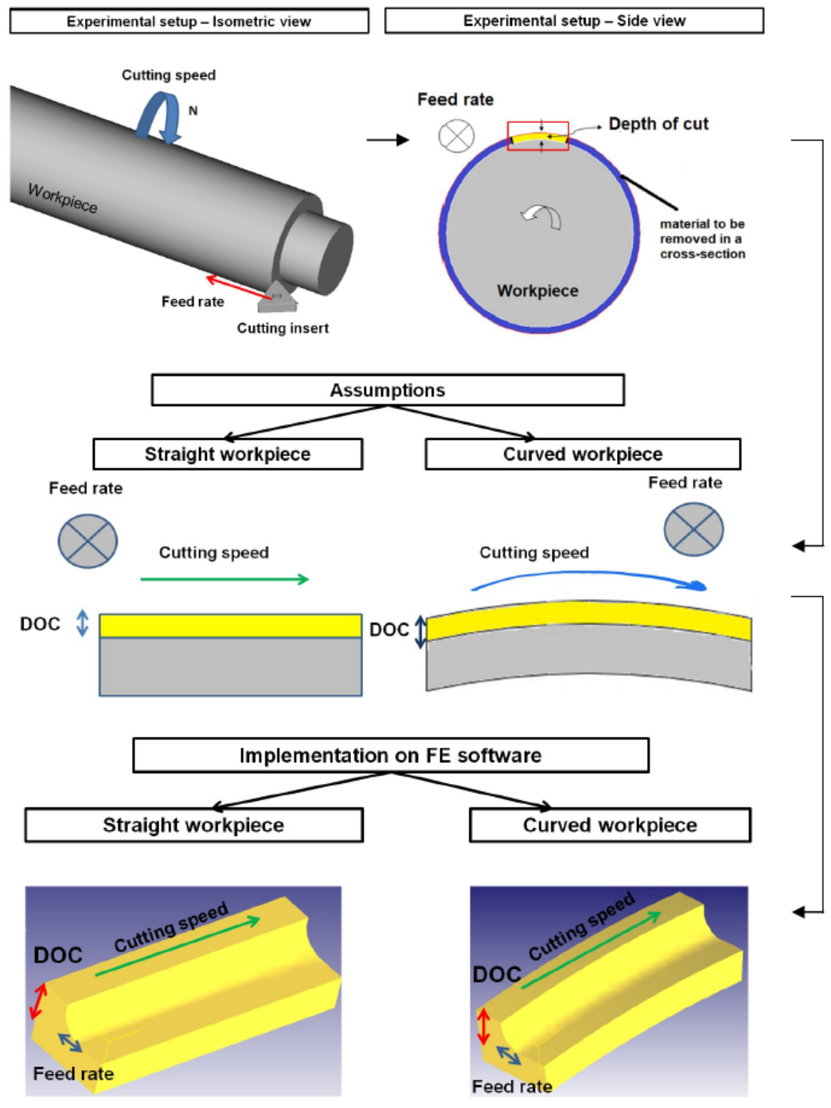
In this work specifically, the cutting model took into consideration the exact cutting insert geometry and its orientation apart from the depth of cut, feed, and cutting speed, which are also explicitly modeled, as the depth of cut is defined in the vertical direction, the feed is defined as the initial position of the tool relative to the already cut surface, and the cutting speed is the speed along the length dimension of the workpiece, corresponding to the cylindrical workpiece’s circumference in the actual setup. The two modeling approaches that are considered differ in workpiece geometry. As can be seen in Figure 1, beginning from the actual 3D turning setup, the main assumption used in the vast majority of models is that only a part of the real cutting length on a cross-section of the workpiece is modeled [31,32,33]. The main differences between the various models can be found regarding the dimensions of the model, e.g., 2D or 3D, and the workpiece of the modeled workpiece. At first, the workpieces were modeled as block-shaped, but, during the last few decades, the real insert geometry with the nose radius has been taken into account and the workpiece includes a machined part. The final difference, which is investigated in the present study, is related to the overall geometry, which can be simplified to a straight workpiece, especially for workpieces with large diameters, or considered as a curved workpiece, as can be seen in Figure 1 and Figure 2.
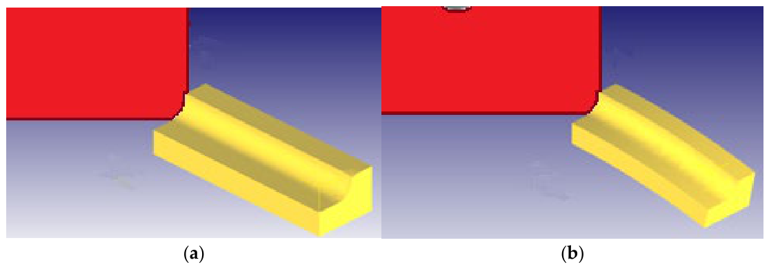
In particular, in Figure 2, it can be seen that in the first model (Model 1), the tool moves in a straight path with sufficient length to achieve stable cutting conditions, whereas in the second model (Model 2) the tool moves in a curved path and the workpiece geometry is also curved, calculated based on the actual workpiece diameter, namely, 45 mm, and desired cutting length, which is equal to the respective arc length in this case. So, the second approach is closer to the actual setup but still considers only a fraction of the total cylindrical workpiece circumference. These assumptions can be considered valid, as, in fact, during turning, the cutting force stabilizes quickly after the contact of the cutting tool and the workpiece, so it is not necessary to model a very long machining length [34,35]. In the second model, with the curved geometry, a fundamental difference is that the contact area becomes variable because the “effective” geometry of contact changes continuously during the cutting process in a cross-section. With a curved workpiece, an additional effect due to the local radius of curvature variation exists, and, as the tool moves along the arc, the contributions to the different force components varies compared to the case with the straight workpiece, depending on the curvature. This variation can have an effect on cutting temperature, as well.
These models were validated through comparison with the experimental results of main cutting force from a previous publication [36]. In this work, turning experiments on Ti-6Al-4V bars of a diameter value of 45 mm were carried out on a conventional lathe under dry cutting conditions. The experiments were designed according to a Taguchi L27 orthogonal array with three parameters, i.e., depth of cut, feed rate, and rotational speed, at three levels each. During the experiments, cutting force components were recorded using a Kistler dynamometer (Kistler Group (legally registered as Kistler Instrumente AG), Winterthur, Switzerland).
After the validation procedure, the effect of process parameters on the predicted cutting temperature and chip morphology under these different conditions were also studied. More specifically, simulations under three different feed rate values, namely, 0.08, 0.18, and 0.33 mm/rev, and two different cutting speed values, namely, 420 and 600 rpm, were carried out, corresponding to cutting speed values of 59.35 m/min and 84.78 m/min. During the experiments, as can be seen in Table 1, the depth of cut was kept constant at 0.5 mm, and the turning process was performed under dry conditions.
The workpiece material is Ti-6Al-4V ELI titanium alloy. This alloy is considered a high-purity alpha–beta titanium alloy with the particularity that it includes a rather tightly controlled amount of interstitial elements (Extra Low Interstitials, e.g., O2, N2, C, Fe). This material is suitable for advanced applications such as biomedical implants and critical aerospace components, with higher ductility, fracture toughness, and fatigue resistance compared to Ti-6Al-4V. As with other titanium alloys, this material presents significant challenges due to its low thermal conductivity, causing accelerated tool wear, built-up edge formation, and tool diffusion. Thus, the selection of appropriate machining conditions based also on simulation results is crucial for this material.
For Ti-6Al-4V ELI, an appropriate constitutive law taking into account the thermo-mechanical phenomena was adopted from the software library. The particular model is considered appropriate for machining simulations, as the material properties were modified based on experimental data. Moreover, the cutting insert is a TNMG 160404 MF2 carbide turning insert (Seco® tools; Fagersta, Sweden). This cutting insert corresponds to a PTJNR2020 toolholder, which was taken into account during the definition of rake, clearance, and lead angles for the positioning of the cutting insert.
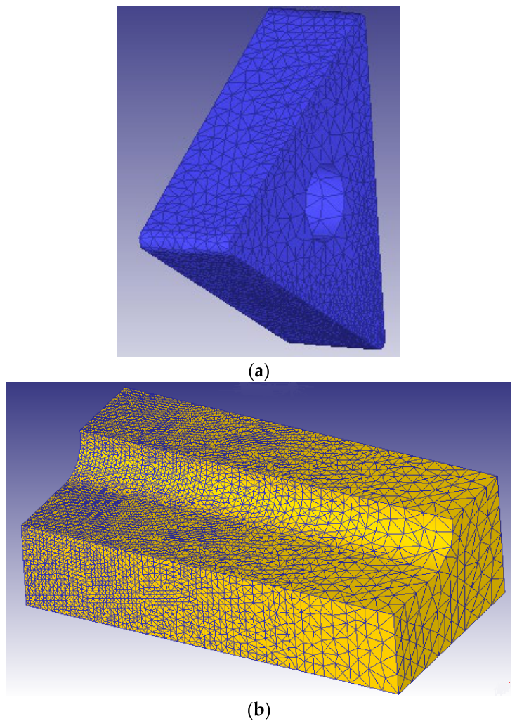
The simulations were carried out in Deform v.12 3D software (Scientific Forming Technologies Corporation (SFTC), Columbus, OH, USA). In the FE simulations, the cutting length was 5 mm (corresponding to an arc of 12.7° for the curved model) and the coefficient of friction value was 0.1, whereas the initial temperature of the cutting environment was equal to 20 °C. The mesh included 3D tetrahedral elements for both the cutting tool and the workpiece, as can be seen in Figure 3. The cutting insert mesh included 15,000 finite elements with particular emphasis near the cutting edge, whereas the number of elements for the workpiece mesh included almost 80,000 elements and was not uniform, with higher mesh density in regions close to the cutting zone or regions with curved geometry. Element separation was allowed due to the large deformations in order to enable the creation of the chip, and, as the cutting insert moved, automatic adaptive re-meshing was applied when necessary to avoid mesh distortion. Moreover, an updated Lagrangian formulation was used for the coupled thermo-mechanical model. In Deform v.12 3D software, the adaptive re-meshing strategy is used to maintain high element quality during large plastic deformations occurring due to contacts and intense material flow. The software continuously monitors the distortion of elements, their aspect ratio, and strain gradients and automatically leads to local remeshing in areas with high strain gradients and sharp curvature of intense contact pressure when predefined distortion criteria are exceeded. Then, the distorted elements are replaced by finer elements with high quality in order to preserve the state variables and ensure numerical stability, while in unaffected regions the size of the elements is higher to reduce computational cost.
For the determination of mesh size, the choice was made based on some preliminary runs, but, given that the adaptive re-meshing technique was adopted, the use of mesh of higher density in the crucial areas can ensure high accuracy of the results. In any case, the workpiece was fixed in space, and heat generation could occur due to friction work and plastic deformation.

3. Results and Discussion

3.1. Cutting Force

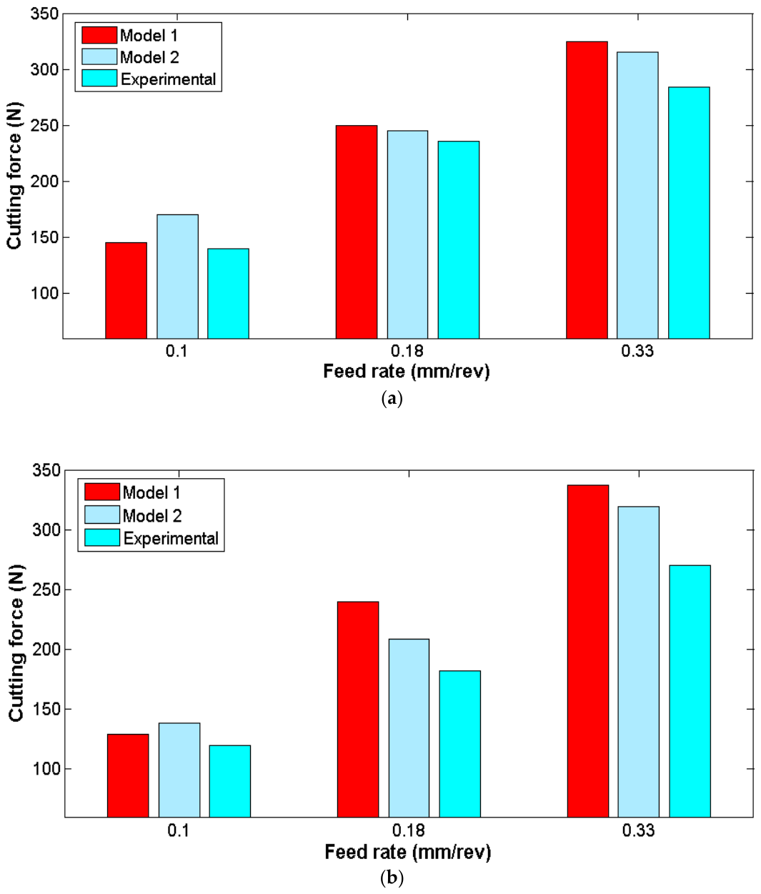
The two machining setups were at first compared regarding the prediction of the main cutting force based on the experimental results. The comparison was carried out based on multiple cases in which feed rate and rotational speed were varied. The results are presented in Table 2 and also depicted in Figure 4a,b. At first, it can be seen that the results are consistent with the trends observed in the relevant literature and the physics of the turning process, as the increase in feed rate and decrease in rotational speed lead to higher cutting force values [37,38]. These results indicate that there is a noticeable difference between the two different machining setups. More specifically, the results of the model that considers a straight workpiece (Model 1) are closer to the experimental ones only for the cases with lower feed rates for both rotational speed values but have greater deviations for all the other cases. On the other hand, the model with the curved workpiece (Model 2) has a relatively high deviation at the lowest feed rate conditions, but the predicted values of this model are much closer to the experimental ones for all the other cases at higher feed rates and across both rotational speed values. In general, both machining models tend to over-predict the value of the main cutting force, with Model 1 exhibiting higher over-prediction, mainly due to its inability to capture the force reduction due to the variable contact area during actual machining.
This behavior can be explained mainly by differences in chip formation and contact conditions between the cutting insert and the workpiece in the two different machining setups. At lower feed rates, when uncut chip thickness is thinner and tool–workpiece engagement is smaller, the deformation zone is dominated primarily by the primary shear rather than secondary shear, and workpiece curvature plays a less important role. So, the constant tool–chip contact geometry and simplified kinematics assumed in the case of the straight workpiece can provide reliable results due to the negligible error of predicted stresses and temperatures induced by this assumption. However, at higher feed values, when thicker uncut chip thickness is expected, the influence of the secondary deformation zone and friction conditions in the tool–chip interface can affect the cutting force calculation more severely, as the calculation of contact-related quantities is more dependent on the local variations of the curvature and the actual tool trajectory. In these cases, the curved workpiece geometry that leads to variable contact geometry and the changing effect of the rake angle along the toolpath contribute to the more realistic representation of the continuously varying conditions during the actual machining of cylindrical or rotated workpieces. Finally, the observed independence of the trends with respect to the rotational speed further indicates that they were mainly relevant for the difference in feed rate rather than the inertia or thermal phenomena occurring at different rotational speeds. Thus, the overall evaluation of the two models indicates that the model with the curved workpiece is more capable of simulating the turning experiment.
The deviation could be attributed to the assumption of the isotropic material model, which does not take into account workpiece microstructure explicitly, probable underestimation of the dynamic recrystallization and beta-phase softening effect, or reduced chip segmentation, which does not allow for further reduction of cutting force. Moreover, if the experimental force deviation was taken into account, the predicted force value could probably be within the force deviation range, indicating a definitely acceptable value. However, as in the present case, only the comparison with the average experimental force value is available; this further evaluation of the accuracy of the predicted values is not possible.
Apart from the comparison of the two different models, the variation of the cutting force with respect to the feed rate and rotational speed were analyzed. The results verify the anticipated trend of cutting force with respect to the increase in feed rate, which produces a gradually increasing force value, as well as the slightly decreasing trend of force values with respect to the rotational speed increase. In the case of feed rate, the increase in contact area and the severity of tool–workpiece engagement consequently lead to higher cutting force. Regarding the rotational speed, the variation in cutting force actually occurs due to the interplay of two competing phenomena occurring during machining, namely, work hardening and thermal softening. When the rotational speed is higher, the strain rate near the tool–workpiece contact area becomes higher, leading to intense work hardening effects, but, at higher rotational speed, the temperature also becomes higher, leading to thermal softening phenomena after a threshold temperature is reached. Thus, the increase in force due to work hardening is countered by the thermal softening effect, and, usually, a small decrease in force is observed.

3.2. Cutting Temperature

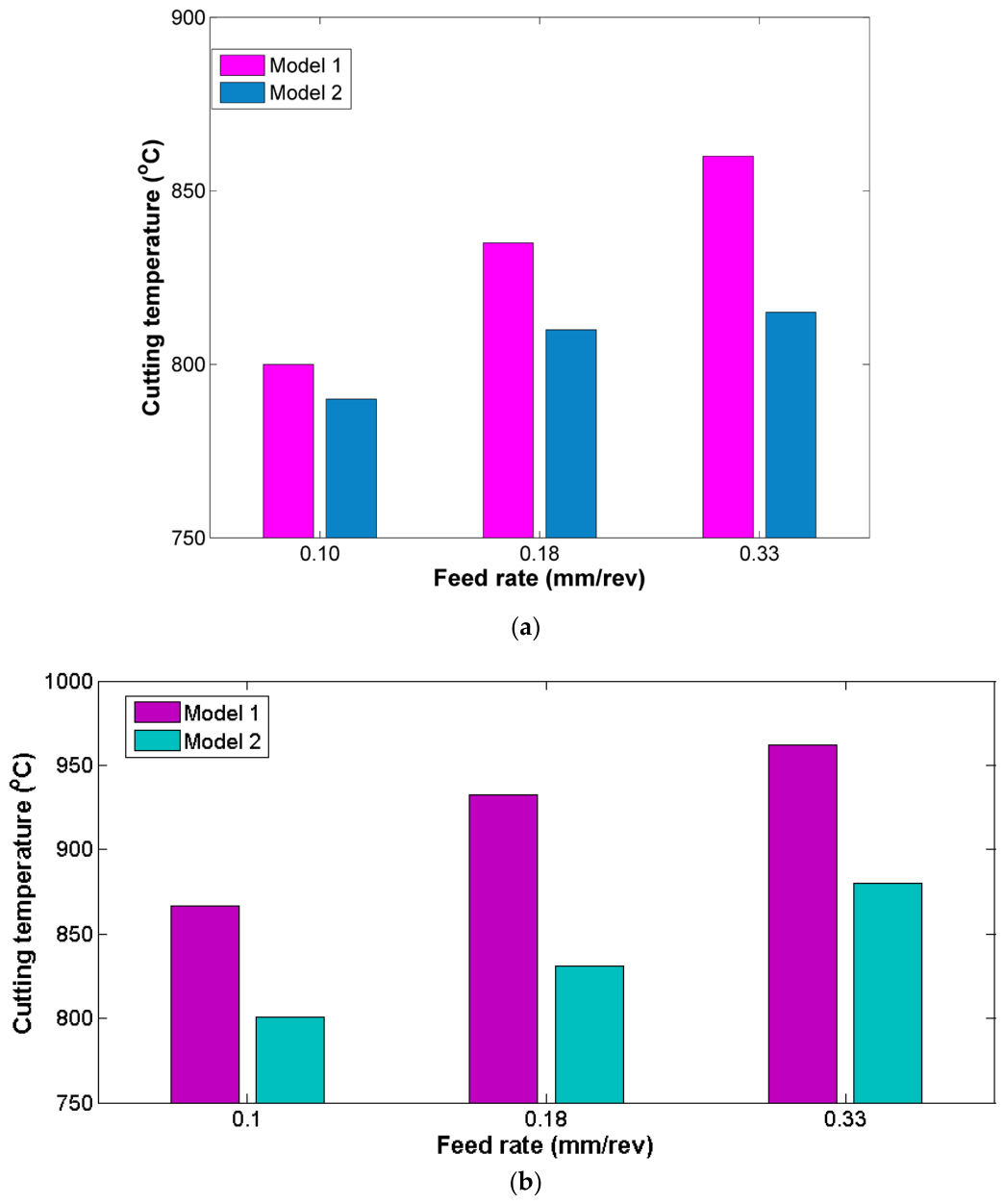
After the two models were evaluated, compared to the experimental results of cutting forces, average cutting temperature values were also analyzed. The model with the straight workpiece geometry predicts an almost proportional increase in the average temperature of the workpiece with respect to the increase in feed rate, especially for the lower rotational speed value, as can be seen in Figure 5a,b. However, the model with the curved workpiece geometry predicts a more gradual increase in the temperature, especially between the two highest feed values for both rotational speed values. In most cases, the temperature is higher for Model 1 than for Model 2.
The differences between the models are mainly related to the different contact conditions in each case. For Model 1, the constant contact conditions reasonably lead to the almost linear trend with feed rate, whereas for Model 2 the tool–workpiece engagement is variable, as was discussed in Section 2, with a different distribution of heat generation along the tool path also partially due to the change in the orientation of the material flow, which can diffuse heat generation over a slightly larger region, leading consequently to lower temperature rise.
Moreover, both models can capture the anticipated variation in cutting temperature with respect to the two process conditions appropriately. In the case of feed rate, the increase in contact area and intensity of tool–workpiece engagement conditions leads to higher temperature values, whereas the increase in rotational speed also leads to an expected increase in temperature due to the increased deformation rate. These findings are consistent with the physics of the process and are supported by the results of numerous experimental studies showing the same trends regarding both feed rate and cutting speed [39,40]. Moreover, a more detailed experimental study carried out for various types of workpiece materials [41] clearly shows that for non-ferrous materials such as Ti-6Al-4V in the specific cutting speed range (59.35–84.78 m/min), the temperature increases with the increase in cutting speed, whereas only for much higher cutting speed values the temperature begins to decrease. The difference between the two models is 50 °C at most, and although a direct temperature measurement was not available in the related experiment, it is expected that Model 2 provides more accurate predictions due to the more realistic representation of process kinematics and contact conditions based on the curved geometry.

3.3. Chip Morphology

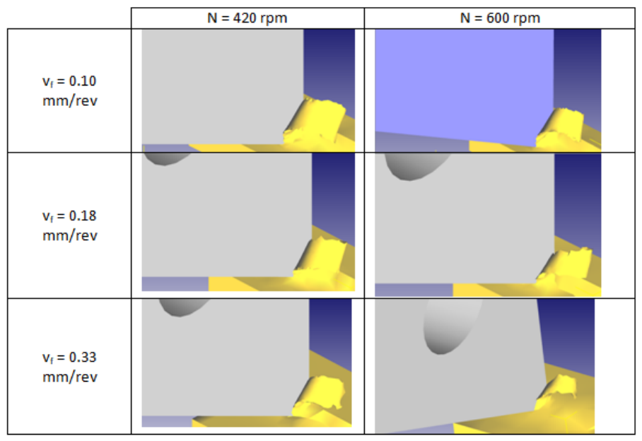
After the simulations were carried out, the evolution of chip morphology was analyzed, as it is also an indicator of machinability and could be affected by the use of a different model. The analysis of chip morphology, shown in Figure 6, revealed that noticeable differences mainly occur when the feed rate is increased. In fact, when chip morphology is compared under different conditions at the same point of the toolpath, the chip has a tendency to become curly from the early stages of the turning process, except for the case with the highest feed rate, where it has the tendency to move further upwards before eventually it bends to create the final form. Generally, feed rate directly affects undeformed chip thickness, so it has a clear impact on chip morphology. As for low feed rates, the chip is more continuous, whereas at higher feed rates the chips are thicker, less flexible, and more irregular. In the present work, for the selected feed rate range, chip morphology did not shown any irregularities and remained continuous.
In the case of different rotational speeds, the differences in chip morphology are negligible. Rotational speed usually affects the chip mainly through thermal effects, as at higher rotational speeds the thermal softening becomes more important and influences the chip generation process. In the present case, the increase in rotational speed from 420 to 600 rpm was not sufficient to alter chip morphology significantly.
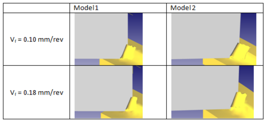
Apart from machining parameters, the choice of machining setup type could have an effect on chip morphology depending on the specific case. In the present work, the choice of a different machining setup did not affect chip morphology considerably, as can be seen in Figure 7. In all of the presented cases, chip formation is almost identical, despite some local variations in chip flow, suggesting that the use of a different machining setup is affecting chip formation less than the cutting force and temperature. As in both setups the workpiece has the same geometry apart from the curvature, it can be concluded that for the same machining conditions the shape of the chip is not affected unless the curvature change is more radical, e.g., if the workpiece diameter is smaller. For the same machining length, the arc could correspond to a larger angle.

4. Conclusions

In this study, the effect of the modeling setup on the accuracy of the turning simulation results was investigated. Two different setups, one with a straight geometry and one with a curved geometry, were compared for different process conditions, namely, feed rate and rotational speed values, during Ti-6Al-4V ELI workpiece machining. From these investigations, several important conclusions were drawn:
  • The model with straight workpiece geometry can predict the machining forces with better accuracy at lower feed rates for both rotational speed values, exhibiting only a slightly higher value, but the deviation becomes larger for higher feed rates, exceeding error values of 10%, due to its inability to model the variability of contact conditions in actual machining. Thus, this model becomes less reliable in these cases.
  • The model with straight workpiece geometry predicts an almost linear correlation of the cutting temperature with the feed rate, with the cutting temperature varying between 800 and 860 °C for rotational speed of 420 rpm and between 860 and 960 °C for rotational speed of 600 rpm.
  • On the other hand, the model with a curved geometry exhibits a larger deviation regarding the prediction of cutting force when the feed rate is low, but, for higher feed rates, when tool engagement is more complex, accuracy is much higher, with error values usually less than 10% due to its ability to directly represent the variations in contact conditions, a very promising finding. Moreover, this model predicts a narrower difference of cutting temperature between various cases, i.e., 790–815 °C at 420 rpm and 800–860 °C at 600 rpm, and smaller temperatures than the model with straight geometry, as heat generation along the tool path is captured more realistically.
  • Differences in chip morphology between the two models were not very significant, whereas only feed rate was shown to lead to some noticeable differences in chip morphology.
These results are important for the increase in predictive accuracy of FE models of turning, showing the capabilities of the curved model, which more closely simulates the machining setup. However, further studies are required in order to fully investigate the potential of this model. Current research will be extended towards the examination of more cases based on additional experiments, e.g., with different workpiece materials to gain deeper insight into the differences between the two types of models.

Author Contributions

Conceptualization, N.E.K. and N.M.V.; methodology, N.E.K., N.A.F. and N.M.V.; software, N.E.K.; validation, N.E.K. and N.A.F.; formal analysis, N.E.K.; investigation, N.E.K.; resources, N.A.F. and N.M.V.; data curation, N.E.K.; writing—original draft preparation, N.E.K.; writing—review and editing, N.E.K., N.A.F. and N.M.V.; visualization, N.E.K.; supervision, N.M.V.; project administration, N.M.V. All authors have read and agreed to the published version of the manuscript.

Funding

This research received no external funding.

Data Availability Statement

The original contributions presented in this study are included in the article. Further inquiries can be directed to the corresponding author.

Acknowledgments

The authors would like to express their sincere gratitude to Panagiotis Kyratsis from the Department of Product and Systems Design Engineering, University of Western Macedonia, Greece, for providing access to computational resources for the simulations in the Deform® 3D environment v.12.

Conflicts of Interest

The authors declare no conflicts of interest.

References

  1. Özel, T.; Ulutan, D. Prediction of machining induced residual stresses in turning of titanium and nickel based alloys with experiments and finite element simulations. CIRP Ann. 2012, 61, 547–550. [Google Scholar] [CrossRef] [Scilit]
  2. Gupta, M.K.; Korkmaz, M.E.; Sarikaya, M.; Krolczyk, G.; Günay, M. In-process detection of cutting forces and cutting temperature signals in cryogenic assisted turning of titanium alloys: An analytical approach and experimental study. Mech. Syst. Signal Process. 2022, 169, 108772. [Google Scholar] [CrossRef] [Scilit]
  3. Li, Q.; Wu, Z.; Ji, B.; Zhang, S.; Tu, R. Cutting Performance of TiN/TiSiN Coated Tool during Turning of Ti6Al4V Titanium Alloy. J. Mater. Eng. Perform. 2025, 34, 9374–9387. [Google Scholar]
  4. Afrasiabi, M.; Saelzer, J.; Berger, S.; Iovkov, I.; Klippel, H.; Rothlin, M.; Zabel, A.; Biremann, D.; Wegener, K. A Numerical-Experimental Study on Orthogonal Cutting of AISI 1045 Steel and Ti6Al4V Alloy: SPH and FEM Modeling with Newly Identified Friction Coefficients. Metals 2021, 11, 1683. [Google Scholar] [CrossRef] [Scilit]
  5. Soori, M.; Arezoo, B. The effects of coolant on the cutting temperature, surface roughness and tool wear in turning operations of Ti6Al4V alloy. Mech. Based Des. Struct. Mach. 2024, 52, 3277–3299. [Google Scholar]
  6. Obiko, J.O.; Mwema, F.M.; Bodunrin, M.O. Validation and optimization of cutting parameters for Ti-6Al-4V turning operation using DEFORM 3D simulations and Taguchi method. Manuf. Rev. 2021, 8, 5. [Google Scholar] [CrossRef] [Scilit]
  7. Rotello, G.; Umbrello, D. Finite element modeling of microstructural changes in dry and cryogenic cutting of Ti6Al4V alloy. CIRP Ann. 2014, 63, 69–72. [Google Scholar]
  8. Hu, H.J.; Huang, W.J. Tool life models of nano ceramic tool for turning hard steel based on FEM simulation and experiments. Ceram. Int. 2014, 40, 8987–8996. [Google Scholar] [CrossRef] [Scilit]
  9. Muhammad, R.; Ahmed, N.; Roy, A.; Silberschmidt, V.V. Numerical modeling of vibration-assisted turning of Ti-15333. Procedia CIRP 2012, 1, 347–352. [Google Scholar] [CrossRef] [Scilit]
  10. Balaji, J.H.; Krishnaraj, V.; Yogeswaraj, S. Investigation on high speed turning of titanium alloys. Procedia Eng. 2013, 64, 926–935. [Google Scholar] [CrossRef] [Scilit]
  11. Zhang, Y.; Mabrouki, T.; Nelias, D.; Gong, Y. FE-model for titanium alloy (Ti-6Al-4V) cutting based on the identification of limiting shear stress at tool-chip interface. Int. J. Mater. Form. 2011, 4, 11–23. [Google Scholar]
  12. Loschner, P.; Nieslony, P.; Kolodziej, S. Parameter sensitivity study of the Johnson-Cook Model in FEM turning of Ti6Al4V alloy. Materials 2025, 18, 3351. [Google Scholar] [PubMed]
  13. Jain, A.; Khanna, N.; Bajpai, V. FE simulation of machining of Ti-54M titanium alloy for industry relevant outcomes. Measurement 2018, 129, 268–276. [Google Scholar] [CrossRef] [Scilit]
  14. Umbrello, D. Finite element simulation of conventional and high speed machining of Ti6Al4V alloy. J. Mater. Process. Technol. 2008, 196, 79–87. [Google Scholar] [CrossRef] [Scilit]
  15. Bordin, A.; Imbrogno, S.; Rotella, G.; Bruschi, S.; Ghiotti, A.; Umbrello, D. Finite Element Simulation of Semi-finishing turning of electron beam melted Ti6Al4V under dry and cryogenic cooling. Procedia CIRP 2015, 31, 551–556. [Google Scholar] [CrossRef] [Scilit]
  16. Jaiswal, A.P.; Khanna, N.; Bajpai, V. Orthogonal machining of heat treated Ti-10-2-3: FE and Experimental. Mater. Manuf. Process. 2020, 35, 1822–1831. [Google Scholar] [CrossRef] [Scilit]
  17. Li, R.; Shih, A.J. Finite element modeling of 3D turning of titanium. Int. J. Adv. Manuf. Technol. 2006, 29, 253–261. [Google Scholar]
  18. Jagadesh, T.; Samuel, G.L. Mechanistic and finite element model for prediction of cutting forces during micro-turning of titanium alloy. Mach. Sci. Technol. 2015, 19, 593–629. [Google Scholar] [CrossRef] [Scilit]
  19. Ratchev, S.M.; Afazov, S.M.; Becker, A.A.; Liu, S. Mathematical modeling and integration of micro-scale residual stresses into axisymmetric FE models of Ti6Al4V alloy in turning. CIRP J. Manuf. Sci. Technol. 2011, 4, 80–89. [Google Scholar] [CrossRef] [Scilit]
  20. Muhammad, R.; Roy, A.; Silberschmidt, V.V. Finite Element Modelling of Conventional and Hybrid Oblique turning processes of titanium alloy. Procedia CIRP 2013, 8, 510–515. [Google Scholar] [CrossRef] [Scilit]
  21. Abboud, E.; Shi, B.; Attia, H.; Thomson, V.; Mebrahtu, Y. Finite element-based modeling of machining-induced residual stresses in Ti-6Al-4V under finish turning conditions. Procedia CIRP 2013, 8, 63–68. [Google Scholar]
  22. Maroju, N.K.; Pasam, V.K. FE modeling and experimental analysis of residual stresses in vibration assisted turning of TI6Al4V. Int. J. Precis. Eng. Manuf. 2019, 20, 417–425. [Google Scholar] [CrossRef] [Scilit]
  23. Ali, M.H.; Ansari, M.N.M.; Khidhir, B.A.; Mohamed, B.; Oshkour, A.A. Simulation machining of titanium alloy (Ti-6Al-4V) based on the finite element modeling. J. Braz. Soc. Mech. Sci. Eng. 2014, 36, 315–324. [Google Scholar]
  24. Yi, F.; Zhong, R.; Zhu, W.; Zhou, R.; Guo, L.; Wang, Y. Comparative study of friction models in high-speed machining of titanium alloys. Lubricants 2025, 13, 113. [Google Scholar] [CrossRef] [Scilit]
  25. Mishra, S.K.; Ghosh, S.; Aravindan, S. 3D finite element investigations on textured tools with different geometrical shapes for dry machining of titanium alloys. Int. J. Mech. Sci. 2018, 141, 424–449. [Google Scholar] [CrossRef] [Scilit]
  26. Chen, S.; Hou, L.; Li, H.; Jing, X.; Cai, H.; Chen, Y. Multiscale modeling with data-calibrated material parameters for microstructure evolution in Ti5553 machining. J. Manuf. Process. 2026, 162, 21–42. [Google Scholar] [CrossRef] [Scilit]
  27. Zhao, Z.; Zishun, Z.; Jianing, D.; Ming, L.; Baohai, W. Cross-scale simulation of microstructure evolution during orthogonal cutting process based on crystal plasticity finite element method. Int. J. Adv. Manuf. Technol. 2026, 142, 2785–2798. [Google Scholar] [CrossRef] [Scilit]
  28. Wang, Z.; Yin, H. Titanium Alloy Turning Machining Model and Quality Analysis Based on Finite Element Analysis. Manuf. Technol. 2025, 25, 413–423. [Google Scholar] [CrossRef] [Scilit]
  29. Chakroun, Y.; Han, S.; Andre, T.; Cici, M.; Valiorgue, F.; Rech, J. 3D numerical modeling of residual stresses induced in longitudinal turning of a TA6V titanium alloy. Procedia CIRP 2025, 133, 274–279. [Google Scholar] [CrossRef] [Scilit]
  30. Wu, S.; Xue, F.; Liu, G.; Chen, W.; Wang, C. Microstructure evolution of titanium alloy in cryogenic cooling cutting. J. Mater. Process. Technol. 2025, 341, 118914. [Google Scholar] [CrossRef] [Scilit]
  31. Shi, B.; Attia, H. Current status and future direction in the numerical modeling and simuation of machining processes: A critical literature review. Mach. Sci. Technol. 2010, 14, 149–188. [Google Scholar] [CrossRef] [Scilit]
  32. Sadeghifar, M.; Sedaghati, R.; Jomaa, W.; Songmene, V. A comprehensive review of finite element modeling of orthogonal machining process: Chip formation and surface integrity predictions. Int. J. Adv. Manuf. Technol. 2018, 96, 3747–3791. [Google Scholar] [CrossRef] [Scilit]
  33. Melkote, S.; Liang, S.; Özel, T.; Jawahir, I.S.; Stephenson, D.A.; Wang, B. A review of advances in modeling of conventional machining processes: From Merchant to the present. J. Manuf. Sci. Eng. 2022, 144, 110801. [Google Scholar] [CrossRef] [Scilit]
  34. Singh, G.; Teli, M.; Samanta, A.; Singh, R. Finite element modeling of laser-assisted machining of AISI D2 tool steel. Mater. Manuf. Process. 2013, 28, 443–448. [Google Scholar] [CrossRef] [Scilit]
  35. Wolf, J.; Eisseler, R.; Bandaru, N.K.; Dienwiebel, M.; Möhring, H.C. A novel approach for modeling loads on profiled cutting tools. Procedia CIRP 2025, 133, 394–399. [Google Scholar] [CrossRef] [Scilit]
  36. Kechagias, J.; Tsiolikas, A.; Asteris, P.; Vaxevanidis, N. Optimizing ANN performance using DOE: Application on turning of a titanium alloy. MATEC Web Conf. 2018, 178, 01017. [Google Scholar] [CrossRef] [Scilit]
  37. Li, X.; Wei, Z.; Liu, Y.; Guo, M.; Guo, J.; Liu, S.; Wang, M. Mechanism and force modeling by considering wiper edge effect during cutting process of wiper tools. J. Manuf. Process. 2025, 136, 27–42. [Google Scholar] [CrossRef] [Scilit]
  38. Xu, D.; Feng, P.; Li, W.; Ma, Y.; Liu, B. Research on chip formation parameters of aluminum alloy 6061-T6 based on high-soeed orthogonal cutting model. Int. J. Adv. Manuf. Technol. 2014, 72, 955–962. [Google Scholar] [CrossRef] [Scilit]
  39. Sulaiman, S.; Roshan, A.; Borazjani, S. Effect of cutting parameters on cutting temperature of Ti6AlV4 alloy. Appl. Mech. Mater. 2013, 392, 68–72. [Google Scholar] [CrossRef] [Scilit]
  40. Mani, D. Investigate the comparative performance of dry turning Monel 400 alloy by untreated and cryo-treated AlTiN carbide tools. Adv. Mater. Process. Technol. 2024, 10, 1869–1887. [Google Scholar] [CrossRef] [Scilit]
  41. Wang, Z.; Rahman, M. High-speed machining. In Comprehensive Materials Processing, 1st ed.; Hashmi, S., Batalha, G.F., van Tyne, C.J., Yilbas, B., Eds.; Elsevier: Amsterdam, The Netherlands, 2014; Volume 11, pp. 221–253. [Google Scholar]
Figure 1. Detailed representation of the different methodological steps for developing the two models.
Metals 16 00677 g001
Figure 2. Different simulation setups used in this work (zoomed view): (a) straight workpiece, (b) curved workpiece.
Metals 16 00677 g002
Figure 3. Images of the employed mesh on the (a) cutting insert, (b) workpiece.
Metals 16 00677 g003
Figure 4. Comparison of the simulation and experimental results regarding cutting force: (a) rotational speed of 420 rpm, (b) rotational speed of 600 rpm.
Metals 16 00677 g004
Figure 5. Comparison of the two model types regarding the cutting temperature: (a) rotational speed of 420 rpm, (b) rotational speed of 600 rpm.
Metals 16 00677 g005
Figure 6. Chip morphology for different cutting conditions (Model 1).
Metals 16 00677 g006
Figure 7. Comparison of chip morphology under different conditions for the two models (N = 600 rpm).
Metals 16 00677 g007
Table 1. Experimental conditions.
ConditionsValues
Feed rate (mm/rev)0.1, 0.18, 0.33
Rotational speed (rpm)420, 600
Depth of cut (mm)0.5
Workpiece diameter (mm)45
Cooling methodNo (dry conditions)
Table 2. Cutting force results from the two different models.
Feed Rate (mm/rev)Rotational Speed (rpm)Cutting Force Model 1 (N)Cutting Force Model 2 (N)Cutting Force Experiment (N)
0.10420145170140
0.18420250245236
0.33420325315284
0.10600129138120
0.18600240206182
0.33600337316270
Disclaimer/Publisher’s Note: The statements, opinions and data contained in all publications are solely those of the individual author(s) and contributor(s) and not of MDPI and/or the editor(s). MDPI and/or the editor(s) disclaim responsibility for any injury to people or property resulting from any ideas, methods, instructions or products referred to in the content.