Article

Fatigue Behavior of Hybrid Additive/Subtractive Manufactured Ti-6Al-4V

1
Department of Mechanical Engineering, Baylor University, Waco, TX 76706, USA
2
Point-of-Need Innovations Center, Baylor University, Waco, TX 76706, USA
*
Author to whom correspondence should be addressed.
Metals 2026, 16(6), 673; https://doi.org/10.3390/met16060673
Submission received: 27 April 2026 / Revised: 9 June 2026 / Accepted: 10 June 2026 / Published: 18 June 2026
(This article belongs to the Special Issue Research on Fatigue Behavior of Additively Manufactured Materials)

Abstract

Additive–subtractive hybrid manufacturing (ASHM) allows for the rapid manufacturing of metal components with complex and precise geometries for ready-to-use or near-ready-to-use applications. Laser wire-directed energy deposition (LW-DED) can be used to quickly manufacture metal components, while CNC machining can achieve precise geometric tolerances. In this study, Ti-6Al-4V alloy specimens were fabricated using an LW-DED process combined with CNC machining and tested to evaluate the effects of ASHM on mechanical performance. Post fabrication, the Ti-6Al-4V material was evaluated through hardness mapping, monotonic tensile testing, and fully reversed axial fatigue testing. Vicker’s micro-hardness mapping showed a range of hardness results from 300 to 350 HV in the ASHM Ti-6Al-4V that remained consistent throughout the build. Tensile results showed a similar response to cast and wrought Ti-6Al-4V, with an average yield stress of 819.4 MPa, ultimate tensile strength of 935.5 MPa, and modulus of 119 GPa. When tested in fatigue, the material had a reduced life compared to wrought Ti-6Al-4V, which is attributed to defects originating from the additive process. While no run-outs were observed from the testing, the fatigue results remain aligned with trends reported for other methods of additively manufactured Ti-6Al-4V. Fully reversed high-cycle fatigue loading revealed that the ASHM-fabricated Ti-6Al-4V fell into a Basquin power-law fit with a fatigue strength coefficient of 1942 MPa with a fatigue strength exponent of −0.115. The fatigue life of the ASHM material is found to be dependent on the resulting porosity of the material that stems from the LW-DED process used in the ASHM process described.

1. Introduction

Titanium alloys are considered in aerospace applications for engine components, landing gear parts, tail cones, airplane ducts and other components due to their high strength-to-weight ratio, formability at elevated temperatures, and machinability [1,2,3]. With additive manufacturing (AM), metals including Ti-6Al-4V can be quickly formed and shaped into complex geometries [3,4]. While the use of additive manufacturing has been widely investigated, there are comparatively fewer studies on the effects of additive and subtractive hybrid manufacturing (ASHM) on the fatigue response of Ti-6Al-4V structures. With the advancement of AM in the manufacturing of different component structures, ASHM could allow for the rapid net-shape manufacturing of these complex aircraft component geometries with reduced post-processing requirements.
AM allows for the quick creation of complicated geometries through a variety of methods. Past studies have focused on using AM for creating Ti-6Al-4V using laser powder bed fusion, wire arc AM, laser-engineered net shaping (LENS), and direct energy deposition (DED) [2,4,5,6,7,8,9,10,11,12,13,14,15]. When compared to wrought Ti-6Al-4V, previous studies with powder bed fusion by Li et al. [2] indicated comparable performance to wrought and cast forms, and that the resulting fatigue life was driven by the surface quality and microstructural defects. Li et al. also compared their results with those from studies with laser and electron beam powder bed fusion-manufactured Ti-6Al-4V and reported minimal variation in tensile strength or fatigue life when compared to the wrought [2]. Dang et al. [5] and Keist et al. [6] evaluated the effects of porosity and geometric design considerations when using AM Ti-6Al-4V manufactured using laser powder DED. Dang et al. [5] saw that with pore size in powder-based laser DED significantly influences the fatigue response of Ti-6Al-4V, and Keist et al. [6] saw that build orientation significantly affected the alloy’s mechanical properties. Build direction effects were observed due to longer grains consistent with β-Ti, which increased tensile strength in the loading direction and along build boundaries where β-Ti grains were more prevalent. Sterling et al. [7] saw similar results from tensile and fatigue testing for LENS-manufactured-and-wrought Ti-6Al-4V. In their examination of the fatigue life, Sterling et al. saw that there was worse fatigue life using a strain life approach in additively manufactured Ti-6Al-4V due to the presence of large voids in LENS-processed coupons [7]. Other works, such as Renzo et al., looked at the multiaxial fatigue of selective laser-melted Ti-6Al-4V and found that the failure modes saw internal and surface crack initiation from defects and saw slightly lower than wrought tensile properties with heat treatment and saw run-out at lower stresses [8]. These studies show that while the tensile response of additively manufactured Ti-6Al-4V is often comparable to wrought material, print quality and porosity significantly impact the fatigue life. However, there is minimal work showing the contributions of the hybrid manufacturing of ready-to-use components from existing AM literature for Ti-6Al-4V in both powder-based and wire-based feedstocks.
Aside from powder-based methods, wire-based feedstocks are often used with laser or plasma arc DED systems [11,12,13,14,15,16,17]. Chekir et al. [11] investigated the influence of travel speed on the residual stress relief of laser wire and powder DED Ti-6Al-4V, showing that travel speed plays a significant role on the final microstructure quality of the printed coupons. At approximately 7.2 mm/s in printing, Chekir et al. observed a more refined microstructure with α-Ti platelets thickness comparable to those produced by laser powder DED [11]. At lower speeds, such as 1.4 mm/s, recrystallized β-Ti grains were formed along the boundaries and α-Ti grains developed with shorter thicknesses, leading to reduced strength in the coupon [11]. When comparing feedstock type in fatigue performance, Nakano et al. [12] reported similar results to those observed in LENS-produced coupons by Sterling et al. [7]. Overall, a 107 cycle run-out was observed in all coupon types including wrought, LENS, and laser DED when loaded between 600 and 700 MPa. Both studies are consistent with the work by Brandl et al. [18] showing that larger α-Ti grains lead to a decrease in the structural strength of additively manufactured Ti-6Al-4V [7,12,18]. When investigating differences in feedstock, Nakano et al. found that the variation in α-Ti grain content compared to LENS-produced Ti-6Al-4V was due to slow cooling rates, which resulted in higher strengths in the wire-based laser DED-fabricated coupons [12]. These works have shown the effects of AM feedstock on the resulting fatigue life properties of the material and discuss how the microstructure quality can be greatly influenced by the type of feedstock chosen in the AM process. This becomes relevant when extending to the ASHM process as the new unknown becomes the effects that combined additive/subtractive methods have on the resulting microstructure and surface quality as parts are created for ready-to-use applications.
Works have attempted to use wire feedstocks in conjunction with machining methods in the past to evaluate the effects of dimensional accuracy, and the effects of travel speed on the microstructure of the resulting specimens. Additional work by Singh and Deoghare [13,14,15] examined Ti-6Al-4V produced on the Meltio laser wire DED system, focusing on the dimensional accuracy, microstructure, tensile response and fatigue life of additively manufactured Ti-6Al-4V using a 45° raster angle orientation [13,14,15]. Singh and Deoghare found that higher layer thicknesses reduced fatigue life and printing at speeds of 10mm/s, which promoted α-Ti grain formation, leading to the reduction in strength in the printed materials [15]. Additionally, the 45° raster angle noted a reduced tensile strength compared to Nakano et al. and Sterling et al., suggesting that build direction and raster angle may contribute to α-phase morphologies and pore formation [7,12,13]. Despite extensive work examining the mechanical behavior of AM Ti-6Al-4V, most studies evaluate samples in printed geometries, with limited attention to the effects of ASHM on the response of the material, or the resulting material surface.
Although prior studies examined machining as a way of controlling surface defects for fatigue life testing, few studies consider ASHM systems [19,20,21,22]. Li et al. [19] investigated 316L stainless steel fabricated using the ASHM system, showing that the addition of a post-fabrication heat treatment to the coupons at 400 °C for two hours effectively eliminated the residual stresses, and yielded strengths similar to wrought 316L stainless steel. Similarly, work by Yan et al. [22] used a powder-based ASHM process to study Ti-6Al-4V and characterize its hardness and microstructure. Yan et al. [22] reported similar results to previous powder-based systems observing α-Ti grains along the boundaries of the material coupons. Their findings showed that layer height and input energy density impacted the final tensile properties of the build. While powder-based ASHM systems have been characterized, there are few studies examining the relationship between ASHM and the tensile and fatigue life of Ti-6Al-4V using a wire-based DED additive system.
AM provides the ability to rapidly produce and implement metal components with complicated geometries, making it attractive for aerospace applications. For Ti-6Al-4V, laser wire DED is a popular method that offers reduced porosity compared to powder-based DED methods. This investigation aims to understand the effects of hybrid additive/subtractive manufacturing on Ti-6Al-4V and its resulting fatigue life by using a hybrid LW-DED and CNC system to build and shape coupons for fatigue evaluation. This study analyzes the fatigue and tensile behavior of as-built ASHM Ti-6Al-4V to establish process–property relationships and enable future comparisons. It addresses the overall effects of the combined ASHM process and the sequential post-processing, rather than the contributions of the individual processing steps. The results of this study show that ASHM using LW-DED and CNC contributes to the existing research on Ti-6Al-4V by allowing for a direct analysis of rapidly manufactured using ASHM for ready-to-use components. Through the evaluation of parts made in their ready-to-use state after going through the ASHM process, the results of this work demonstrate how AM processes in ASHM dominate the failure mechanisms present in the material despite the use of CNC machining and grinding operations.

2. Materials and Methods

2.1. Material Deposition

Ti-6Al-4V alloy wire (1 mm diameter) was deposited on a 76 mm by 76 mm grade 5 Titanium substrate using a 3-axis Phillips Meltio-Haas, Worcester, MA, USA, CNC ASHM system. The material was deposited on the substrate using a laser power of 1050 W, an argon gas flow rate of 30 L/min, a wire extrusion rate of 16.8 mm/s, and traverse rate of 546 mm/min. Ti-6Al-4V was deposited on the substrate using the Meltio laser wire DED, Linares, Jaen, Spain, in a rectangular prism with a nominal 25 mm height, 19 mm width, and 70 mm length. The wire was deposited on the substrate in a 0/90° raster angle for each layer with a 40 s cool down between layers to avoid thermal runaway in the build. Figure 1 shows a diagram of the process of manufacturing the test coupons.
Once the final layer was deposited, the part was allowed to cool under continuous argon flow to limit oxidation prior to machining the rectangular prism to the final coupon geometry. After cooldown, a 12.7 mm diameter carbide end mill was used to machine fatigue specimens utilizing the geometry of Avery et al. [23], Rutherford et al. [24], and Anderson-Wedge et al. [25]. Machining was conducted at a feed rate of 155 mm/min with a cooling fluid until the dogbone profile was reached as shown in Figure 1. After profiling, the Ti-6Al-4V deposition was sliced into 2.5 mm nominally thick tensile coupons using a M1200S wire electrical discharge machine (EDM) from Mitsubishi, Tokyo, Japan. Coupons were ground stepwise using 240-, 320-, and 600-grit sandpaper to remove the recast layer and provide a suitable surface finish for fatigue testing. The surface roughness of the specimens was evaluated using a VHX-7000 series digital microscope from Keyence, Itasca, IL, USA. Areal surface parameters (Sa, Sz) were used instead of traditional linear surface profile (Ra, Rz), since the area parameters are captured across the gage surface, eliminating directional biases in the measurement inherent from grinding direction. Surface roughness evaluation showed that specimens had an average arithmetical mean high (Sa) of 12.36 ± 4 µm with an average maximum height (Sz) of 64.8 ± 30 µm. The machine marks left from grinding appeared in the transversal direction of the build; with reference to the orientation in Figure 1d, the machine marks were along the y direction. Figure 1 shows a representation of the final tensile coupon geometry. All specimens were tested in the as-built condition with no additional post-processing. Three separate builds were made using these parameters and tests were conducted on samples from each build for comparison.

2.2. Metallography and Fractography

Microstructural evaluations were performed on cut sections of the grip regions of the tensile test coupons taken from the top and bottom of the build to look at the local modulus and micromechanical behavior of the ASHM Ti-6Al-4V. The specimens were mounted in a conductive resin then ground stepwise to 1200 P followed by polishing in a diamond suspension solution. Metallographic specimens were finished by vibratory polishing in a 0.02 micron colloidal solution for 48 h similar to polishing methods used in Deal et al. [26], Takajo et al. [27], and Dyankonov et al. [28]. Metallographic evaluation and post-mortem fractography were conducted using a JEOL, Tokyo, Japan, scanning electron microscope (SEM) and Keyence VHX-7000 series digital microscope. Porosity evaluation was conducted using the Keyence VHX-7000 series digital microscope with built in feature detection software by which the pores were identified with size, aspect ratio, area fraction and average and maximum sizes for the polished specimens. Grain sizes were determined using Keyence images of the polished material and the line intercept method outlined in ASTM E112 [29].

2.3. Hardness, Tensile and Fatigue Testing

Vickers hardness testing was performed using an EmcoTest Duroscan, Salzburg, Austria, Vickers hardness test system according to ASTM E92-23 [30]. Specimens taken from the top and bottom of the build of the ASHM material were hot mounted in a conductive resin and polished as described in the metallography section. Indentations were performed on the specimens using an indentation force of 50 N with indentations lasting 10 to 15 s per indentation in a 16 × 3 grid with a spacing of 0.5 mm between the indents. The hardness maps were oriented in the x-z direction of the build, where 16 indents were performed along the transversal direction of the deposition and three indents were performed in the layer or z direction. Hardness maps were measured for specimens cut from the top and bottom of the build to quantify variations through the build height.
Tensile tests were conducted on an MTS Model 45 electromechanical load frame with mechanical wedge action grips and equipped with a 100 kN load cell. To avoid alignment issues, a ball-socket alignment joint was added on the top grip. Tests were run in displacement control at a rate of 0.06 mm/min to target a nominal strain rate of 0.001 s−1 per ASTM E8 [31]. The test coupon geometry used in tensile and fatigue testing is presented in Figure 1, consisting of a flat bar dogbone specimen of the provided nominal dimensions in Figure 1 with a ±1.5 mm tolerance in all dimensions. Strain was recorded using an MTS 5 mm extensometer. With near failure, i.e., in the last 1 to 2% elongation of the specimen, the extensometer was removed, and the strain data was calculated using crosshead displacement. Data was captured during testing at a rate of 10 Hz for both the load cell and the extensometer. All tests were performed at ambient temperature and humidity conditions, with 25 °C and 56% humidity.
Fatigue tests were performed using an MTS servo-hydraulic load frame with a 100 kN load cell. Three coupons were tested in load control at peak stresses of 500, 600, 700 and 800 MPa with one coupon loaded at 400 MPa for reference at lower loads, yielding 13 total fatigue tests of the ASHM specimens. Should run-out occur, the expected run-out limit is determined to be 107 cycles; however, no runouts were observed in testing as discussed in Section 3. Hydraulic grips were used in loading with a grip pressure of 9MPa to avoid specimen slippage during loading. The load profile was generated using a sinusoidal wave form load with a fully reversed loading condition (R = −1) and a frequency of 10 Hz. Stress levels were selected to target high-cycle and low-cycle regimes consistent with current literature methods [5,14]. All fatigue tests were performed at ambient temperature and humidity conditions as stated in the previous paragraph.

3. Results and Discussion

3.1. Microstructure and Micro-Hardness

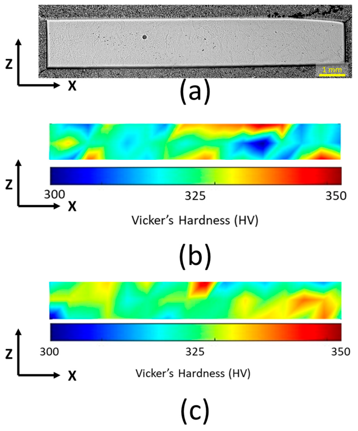
LW-DED-based ASHM allows for the rapid generation of near-net-shape Ti-6Al-4V components; however, the thermal cycling inherent to the LW-DED process can greatly affect the resulting microstructure. The repeated heating and cooling between the deposition of layers of the material promotes columnar grain structures aligned in the build direction or z axis as seen in the cross-sectional example in Figure 2a. In addition to the columnar grain structure, Figure 2a also shows voids in the cross section, ranging from 1 to 250 µm in diameter. Further investigations of the porosity using optical microscopy revealed that while the majority of pore diameters fall within this range, with an average diameter of 6.7 ± 2 µm and standard deviation of 21 µm, there are some outliers, with pores as large as 1 mm in length, resulting from weld bead gaps, lack of fusion between deposited layers, and the lack of melt pool penetration into previous layers [32,33]. The pores appear to be evenly distributed throughout the sample including the sample surface, and overall identified affected porosity was found to constitute 0.35% of the area of measurement. The measured pores have an average aspect ratio of 0.55, with a circularity of 0.19. This type of defect is often indicative of suboptimal process parameters combined with excessive travel speed.
The columnar grains resulting from the manufacturing method were measured using the line intercept technique outlined in ASTM E112 [29]. The average grain size of the ASHM Ti-6Al-4V using a mixture of LW-DED and CNC was found to consist of grains with a grain size number of 12.01 which corresponds to an average grain diameter of 5.6 µm [29]. The columnar grain morphology in the microstructure of the material influences its mechanical properties, and in previous cases, columnar grain structures in Ti-6Al-4V have reported to yield, resulting in Vicker’s micro-hardness values between 310 and 400 HV [34,35]. The results measured in this study using ASHM Ti-6Al-4V are consistent with these values. Figure 2b,c shows the hardness maps between the top and bottom of the build, respectively. While there are some isolated measurements as high as 350 HV in both the top and bottom of the build, the hardness maps show that there is minimal variation in the micro-hardness across the build, with an average hardness for the top and bottom of the build of 327 HV and 328 HV, respectively.
Applying the Tabor relation [35], in which the ultimate tensile strength is approximated as approximately one-third of the Vickers hardness in consistent units, the measured average hardness of 327 to 328 HV corresponds to a predicted UTS on the order of 1070 MPa. The measured UTS of 935 MPa reported in Table 1 is lower than this prediction. The discrepancy is itself instructive, as the Tabor relation reflects the intrinsic matrix response and is relatively insensitive to isolated volumetric defects, while the measured tensile response reflects the integrated behavior of the gauge volume including any porosity present. The difference between the predicted and measured values is therefore consistent with a modest defect-driven reduction in tensile strength, despite the bulk matrix having achieved hardness values comparable to those reported for conventional Ti-6Al-4V [34,35,36].

3.2. Experimental Tensile Behavior

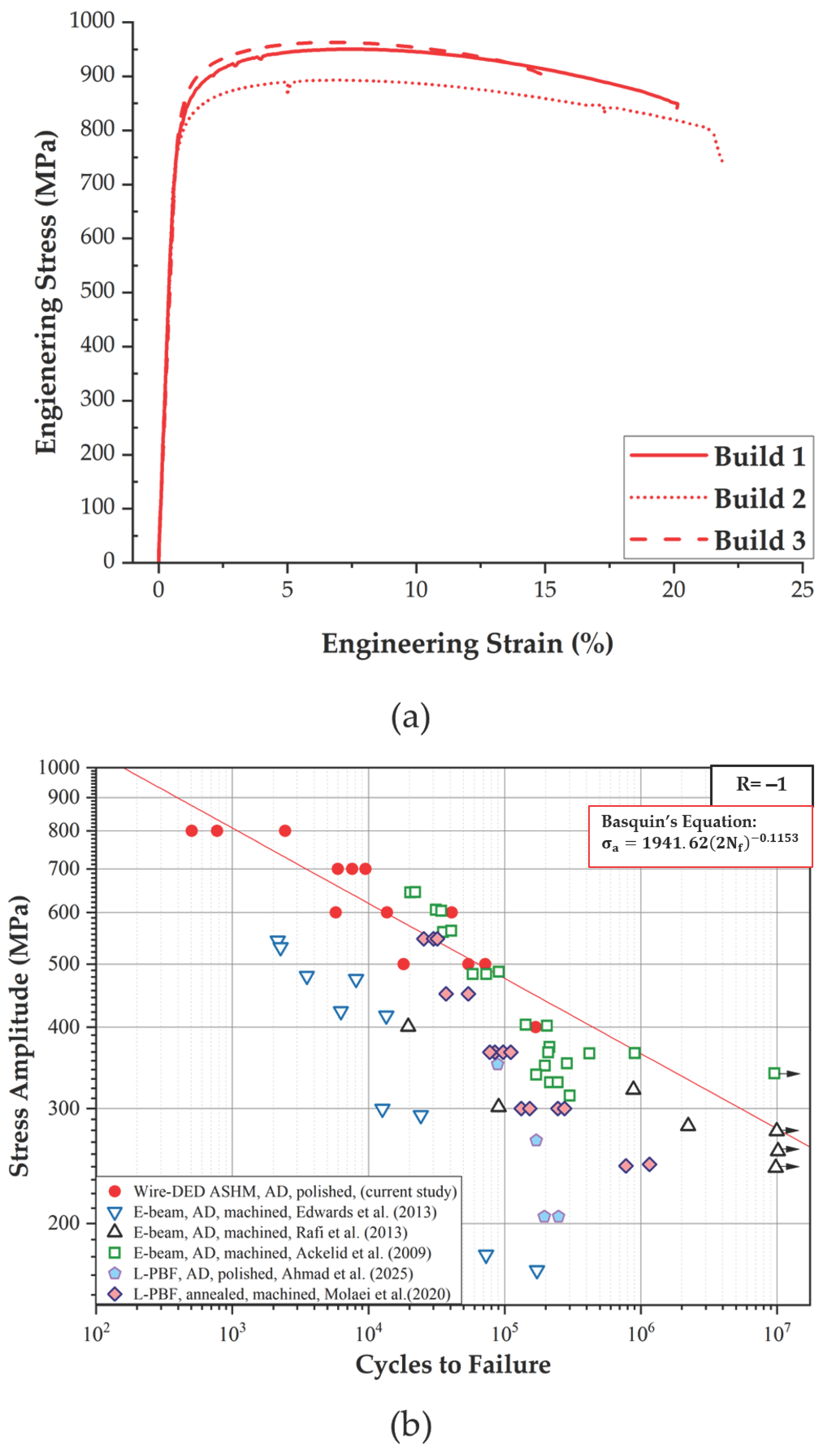
The tensile results of the tested ASHM Ti-6Al-4V samples are summarized in Table 1 with comparisons to wrought Ti-6Al-4V reported in the literature shown in Table 2, and the engineering stress–strain curves shown in Figure 3a. The yield strength was determined using the 0.2% offset line method outlined in ASTM E8 [31]. Minimal variation in the mechanical properties is observed between each test, with a ±6% variation between yield and ultimate tensile strengths, and a variation of up to 11% in the elastic modulus between each test. While the limited sample size precludes a statistical analysis, the observed variability is consistent with reported scatter in additively manufactured materials, which is typically on the order of 2 to 8% [16,37,38]. The elongation to failure demonstrated the highest degree of localized variation among the tensile outcomes, which can be linked to the physical distribution of pores characterized in Section 3.1. Since the volumetric defects distributed throughout the deposition volume, the coalescence of micro-voids can accelerate the crack initiation during plastic deformation, increasing variability in the elongation of the material.
Tensile properties of the ASHM Ti-6Al-4V are comparable to those of cast Ti-6Al-4V [39] with a ductility similar to typical wrought material [40]. The yield strength of the ASHM Ti-6Al-4V reports similarly to other reported LW-DED-manufactured Ti-6Al-4V [13] but differs in ultimate tensile strengths and elastic moduli. Variations between the tensile properties have been attributed to several differences in processing parameters including raster angle and deposition rate [13,41].
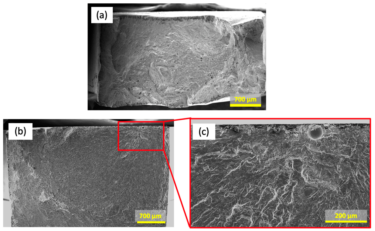
A representative tensile fracture surface is shown in Figure 4a. The fracture surface exhibits a rough and irregular morphology consistent with ductile tensile failures. Similarly to the observations made by Leuders et al. [42] and Wanjara et al. [43], the fracture surface exhibits a “cup”-like morphology with shear tear ridges along the edges indicative of a ductile failure.

3.3. Experimental Fatigue Behavior

With the sensitivity of Ti-6Al-4V to microstructural defects under cyclic loading, the fatigue behavior of the ASHM-fabricated material was evaluated to assess its performance under service-like conditions. The fatigue life of the ASHM Ti-6Al-4V is shown in Figure 3b and the results are shown alongside the fit from the Basquin’s equation [44], and compared to other additively manufactured Ti-6Al-4V [45,46,47,48,49]. The red line in Figure 3b corresponds strictly to the Basquin fit calculated from the ASHM fatigue data generated in this study, or the data points in red shown in Figure 3b without any observed run-outs, yielding a fatigue strength coefficient of approximately 1942 MPa and a fatigue strength exponent of approximately −0.115. While there were run-outs seen in lower loads in other studies [43,44,45,46,47], the observed results from this test, as reported in Figure 3b, and in Table 3, saw no run-outs in the testing of the ASHM Ti-6Al-4V. These parameters are comparable to values reported for laser powder bed fusion and laser wire DED Ti-6Al-4V in the as-built condition [45,48,49] and fall slightly below values typically reported for wrought Ti-6Al-4V, which is consistent with the defect-driven reduction in fatigue strength observed in the present study. The reporting of these parameters is intended to support direct quantitative comparison in future studies of ASHM-produced Ti-6Al-4V.
Consistent with previous observations of the microstructure, the presence of micro-voids in the material can greatly affect the fatigue life of additively manufactured Ti-6Al-4V [2,5,7,12,13,15]. The results of the LW-DED-based ASHM Ti-6Al-4V show similar results where the inclusions of micro-voids in and on the material have reduced the fatigue life of the material. Under fully reversed loading, the fatigue life exhibits a steep decline with decreasing stress amplitude. The fatigue life of the ASHM material shows a rapid decline at lower stress amplitudes most likely due to the presence of process-induced defects. The reduction in fatigue life in the high-cycle regime can likely be attributed to the transition from propagation to initiation-dominated mechanisms, wherein volumetric defects such as the porosity shown in Figure 2a contribute to shorter initiation. While limited data points were generated in the high-cycle regime in the present study, the data are consistent with other studies in the literature [35,45,46,47,48,49]. The majority of the defects in the coupons can be attributed to the porosity and larger outlier pores that are present in the coupons as a result of the LW-DED used in the ASHM process.
It is worth noting that Nakano et al. [12] reported 107 cycle run-out for wire-based laser DED Ti-6Al-4V at stress amplitudes between 600 and 700 MPa, whereas specimens in the present study failed within this same stress range. This difference is most readily explained by the characteristic defect population produced by the two processes. Nakano et al. employed a dot-bead deposition strategy that tends to produce smaller and more dispersed porosity, while the continuous raster deposition used in the present study produced voids on the order of 1 to 250 µm [12]. Under weakest-link fatigue behavior, the presence of even a small number of large defects within the highly stressed volume shifts the S-N response to lower lives regardless of bulk matrix properties. This comparison reinforces the view that process strategy, and not feedstock type alone, governs the fatigue response of LW-DED Ti-6Al-4V.
Figure 3. Plots showing (a) the tensile behaviors of the additive–subtractive hybrid manufactured Ti-6Al-4V specimens showing the resulting variation between specimens measured in testing and (b) the fatigue behavior of the LW-DED and CNC ASHM Ti-6Al-4V specimens compared with the literature values for other fusion-based AM Ti-6Al-4V in fatigue (data from [45,46,47,48,49]) and a Basquin fit for the ASHM data showing a fatigue strength coefficient of 1942 MPa and a fatigue exponent of −0.1153.
Metals 16 00673 g003
To further elucidate the mechanisms underlying the fatigue behavior of the material, a representative fatigue fracture surface tested at 700 MPa that underwent 9532 cycles before failure is shown in Figure 4b. The fracture surface exhibits distinct morphological regions consistent with fatigue mechanism, including an initiation zone, a stable propagation zone characterized by striations, and a final overload region with features similar to those observed on the tensile fracture surface in Figure 4a. Estimation of the relative area fractions indicates that the stable propagation zone accounts for a small fraction of the total fracture surface, while the overload region occupies the majority of the remaining area. This morphology is consistent with an initiation-dominated fatigue life, in which a substantial portion of the cycles are consumed, nucleating a crack from the defect prior to the onset of rapid propagation.
Shown in Figure 4b, the crack initiation site is characterized by a surface-connected void with a √area on the order of 60 to 80 µm, which falls within the upper range of the 1 to 250 µm porosity distribution observed in the as-built microstructure in Figure 2a. This surface-connected void can be attributed to the resulting porosity from the LW-DED process, and appear to drive crack initiation. The crack initiation and propagation appear to be unaffected by the influence of machining marks and their direction, which is perpendicular to the crack initiation and propagation shown in Figure 4b,c. This confirms that the sequential ASHM-finishing chain-mixing CNC machining and 600-grit grinding effectively mitigated any macro-tooling marks left by the CNC or wire EDM cutting processes. Since the specimens were processed through a continuous sequential manufacturing chain, the individual contributions from each processing step are not compared against the fatigue life in this study, meaning the post-mortem fractography serves to qualify the resulting dominant failure mechanisms from the chained manufacturing process.
The presence of the LW-DED defect at the free surface is of particular importance, as surface-connected defects are subject to an elevated stress intensity relative to comparably sized internal defects and are additionally exposed to the surrounding environment [42,49]. Applying the Murakami √area approach, the predicted fatigue strength corresponding to a defect of this size is consistent with the applied stress amplitude of 700 MPa, supporting the conclusion that the observed life is governed by the characteristic defect population rather than by matrix properties [49,50]. This observation further suggests that the surface preparation applied in this study, while sufficient to remove the recast EDM layer, was insufficient in eliminating volumetric porosity intersecting the gauge surface, and that a larger machining stock allowance or a post-deposition densification treatment may be required to suppress surface-connected initiation sites in fatigue-critical applications.
Radiating outward from the initiation site, well-defined fatigue striations are visible, indicating incremental crack advance on each loading cycle. The measured striation spacing in the near-initiation region is on the order of 0.3 to 0.5 µm per cycle, which is consistent with published crack growth rates for Ti-6Al-4V in the stable Paris regime and suggests that the propagation stage itself was not anomalously accelerated by the additive microstructure [42,49,51,52,53]. Crack advance through the material occurred trans-granularly, with evidence of local deflection and faceted features at the boundaries of prior-β columnar grains and α-lath colonies. This interaction between the crack front and the α/β lamellar morphology is consistent with the behavior reported by Leuders et al. [42] and Zhai et al. [38] for additively manufactured Ti-6Al-4V, in which colony-scale deflection contributes modestly to crack growth resistance but does not offset the life reduction imposed by the initiating defect. Comparable initiation morphologies were observed on fracture surfaces from specimens tested at other stress levels in this study, with specimens tested at lower stress amplitudes tending to initiate from larger or more surface-proximate voids. This trend is consistent with weakest-link statistics, wherein the longer lives accessible at lower stress amplitudes allow the governing defect to be drawn from a larger sampled volume and, therefore, on average, a larger defect population [2,49].
Figure 4. Representative fracture surfaces showing (a) a representative SEM image of a tensile fracture surface, showing necking in the specimen as well as a number of micro-voids distributed throughout the specimen fracture surface, and (b) representative SEM images of a fatigue fracture showing the fatigue fracture surface, and (c) magnified image of the fatigue-critical crack initiating from a surface void for a specimen tested at 700 MPa, lasting 9532 cycles.
Metals 16 00673 g004

4. Conclusions

Additive/subtractive hybrid manufacturing (ASHM) allows for the rapid generation of near-net-shape components with minimal post-manufacturing processing such as grinding and polishing to be ready to use. In this investigation, Ti-6Al-4V was manufactured using a hybrid LW-DED and CNC machining to rapidly generate samples for the evaluation of their tensile and fatigue properties using wire EDM to slice individual samples and 600-grit grinding to remove surface machining marks. Due to the use of LW-DED, generated components exhibited a columnar grain structure with an approximate grain size from the line intercept method of 5.6 µm, consisting of evenly distributed voids in the component ranging from 1 to 250 µm in size, with some outliers resulting from gaps between the weld beads and lack of fusion and penetration between layers resulting in voids with lengths as high as 1mm. The resulting microstructure and porosity showed little effect on the hardness of the material, with a range of hardness in the material ranging from 300 HV to 350 HV with minimal variation through the course of the build. The resultant tensile properties of the ASHM material showed consistent results with measured results between cast and wrought Ti-6Al-4V; however, there was increased variability between the tests with elongation yielding the largest variability between tests, being 11%. This increased variability in the elongation can be attributed to the distribution of the pores throughout the material causing an accelerated crack propagation that can be connected to micro-void coalescence in the material due to plastic deformation. The resulting fatigue life of the ASHM material was found to have similar results to fusion-based AM methods in that the voids resulting from the AM process; specifically, LW-DEDs in this case are attributed to the decrease in fatigue life of the resulting ASHM Ti-6Al-4V. These voids served as crack initiation and propagation sites when loaded in high-cycle fatigue. The use of 600-grit grinding, while sufficient to remove the recast layer from EDM as well as any machining marks from CNC, was insufficient in eliminating the volumetric porosity intersecting the surface of the material, leading to the observed limitations of the fatigue life in this work. The presence of these voids may be mitigated through additional process optimization and implementations of post-process techniques for reducing volumetric porosity such as heat treatment. Further work is required to understand the effects of print speed on the microstructure of the material.

Author Contributions

Conceptualization, N.P., R.K., J.B.J. and P.G.A.; Methodology, N.P., R.K., A.I., J.B.J. and P.G.A.; Fabrication, N.P. and R.K.; Software, N.P., A.I. and R.K.; Validation, N.P., A.I. and R.K.; Formal analysis, N.P. and A.I.; Investigation, N.P., A.I., R.K., J.B.J. and P.G.A.; Sources, N.P., R.K. and A.I.; Writing—original draft preparation, N.P., A.I. and R.K.; Writing—revision and editing, N.P., A.I., R.K., J.B.J., P.G.A. and A.S.; Visualization, N.P., R.K., A.S., J.B.J. and P.G.A.; Project management, N.P., A.S., J.B.J. and P.G.A. All authors have read and agreed to the published version of the manuscript.

Funding

This research received no external funding.

Data Availability Statement

The original contributions presented in this study are included in the article. Further inquiries can be directed to the corresponding author.

Acknowledgments

The Authors would like to thank the Baylor University Point-of-Need Innovation (PONI) Center for use of their facilities, equipment and materials for fabrication and testing. Special thanks to members of the PONI Center for their oversight and training on the equipment.

Conflicts of Interest

The authors declare no conflicts of interest.

Abbreviations

The following abbreviations are used in this manuscript:
ASHMAdditive Subtractive Hybrid Manufactured
AMAdditive Manufacturing
LW-DEDLaser Wire-Directed Energy Deposition
DEDDirected Energy Deposition
LENSLaser-Engineered Net Shaping
CNCComputer Numerically Controlled
EDMElectric Discharge Machining

References

  1. Gomez-Gallegos, A.; Mandal, P.; Gonzalez, D.; Zuelli, N.; Blackwell, P. Studies on Titanium Alloys for Aerospace Application. Defect Diffus. Forum 2018, 385, 419–423. [Google Scholar] [CrossRef]
  2. Li, P.; Warner, D.H.; Fatemi, A.; Phan, N. Critical Assessment of the Fatigue Performance of Additively Manufactured Ti–6Al–4V and Perspective for Future Research. Int. J. Fatigue 2016, 85, 130–143. [Google Scholar] [CrossRef]
  3. Liu, Z.; He, B.; Lyu, T.; Zou, Y. A Review on Additive Manufacturing of Titanium Alloys for Aerospace Applications: Directed Energy Deposition and Beyond Ti-6Al-4V. JOM 2021, 73, 1804–1818. [Google Scholar] [CrossRef]
  4. Svetlizky, D.; Das, M.; Zheng, B.; Vyatskikh, A.L.; Bose, S.; Bandyopadhyay, A.; Schoenung, J.M.; Lavernia, E.J.; Eliaz, N. Directed Energy Deposition (DED) Additive Manufacturing: Physical Characteristics, Defects, Challenges and Applications. Mater. Today 2021, 49, 271–295. [Google Scholar] [CrossRef]
  5. Dang, L.; He, X.; Tang, D.; Xin, H.; Wang, X.; Wu, B.; Han, L.; Wang, J. Pore-Induced Fatigue Failure: Critical Pore Criterion for Ti-6Al-4V Alloy Manufactured by Laser-Directed Energy Deposition. Theor. Appl. Fract. Mech. 2024, 129, 104204. [Google Scholar] [CrossRef]
  6. Keist, J.S.; Palmer, T.A. Role of Geometry on Properties of Additively Manufactured Ti-6Al-4V Structures Fabricated Using Laser Based Directed Energy Deposition. Mater. Des. 2016, 106, 482–494. [Google Scholar] [CrossRef]
  7. Sterling, A.; Shamsaei, N.; Torries, B.; Thompson, S.M. Fatigue Behaviour of Additively Manufactured Ti-6Al-4V. Procedia Eng. 2015, 133, 576–589. [Google Scholar] [CrossRef]
  8. Renzo, D.A.; Sgambitterra, E.; Maletta, C.; Furgiuele, F.; Biffi, C.A.; Fiocchi, J.; Tuissi, A. Multiaxial Fatigue Behavior of SLM Ti6Al4V Alloy under Different Loading Conditions. Fatigue Fract. Eng. Mater. Struct. 2021, 44, 2625–2642. [Google Scholar] [CrossRef]
  9. Hassel, T.A.; Brøtan, V.; Sørby, K. Design Considerations for a Directed Energy Deposition Cell. In Proceedings of the Advanced Manufacturing and Automation XII; Wang, Y., Yu, T., Wang, K., Eds.; Springer Nature: Singapore, 2023; pp. 471–478. [Google Scholar]
  10. Gradl, P.; Tinker, D.C.; Park, A.; Mireles, O.R.; Garcia, M.; Wilkerson, R.; Mckinney, C. Robust Metal Additive Manufacturing Process Selection and Development for Aerospace Components. J. Mater. Eng. Perform. 2022, 31, 6013–6044. [Google Scholar] [CrossRef]
  11. Chekir, N.; Tian, Y.; Gauvin, R.; Brodusch, N.; Sixsmith, J.J.; Brochu, M. Effect of Travel Speed and Stress Relief on Thin Ti-6Al-4V Laser Wire Deposits. Mater. Sci. Eng. A 2018, 724, 335–347. [Google Scholar] [CrossRef]
  12. Nakano, Y.; Morita, D.; Shinohara, N.; Ukai, Y.; Sumi, N.; Hashimoto, T. Fatigue Performance of Titanium–Aluminum–Vanadium Alloy Fabricated by Laser-Wire-Based Directed Energy Deposition Forming Dot-Shaped Beads. Mater. Trans. 2023, 64, 296–302. [Google Scholar] [CrossRef]
  13. Singh, S.N.; Deoghare, A.B. Microstructure, Micro-Hardness and Tensile Properties of Ti6Al4V Manufactured by High Layer-Thickness Wire-Feed Multi-Laser Directed Energy Deposition. Mater. Lett. 2023, 340, 134207. [Google Scholar] [CrossRef]
  14. Singh, S.N.; Deoghare, A.B. Macrodimensional Accuracy of Ti6Al4V Parts Manufactured by Wire-Feed High Layer Thickness Continuous Laser Directed Energy Deposition. J. Laser Appl. 2023, 35, 012003. [Google Scholar] [CrossRef]
  15. Ningthemba Singh, S.; Deoghare, A.B. High Layer Thickness Laser Directed Energy Deposition of Ti6Al4V Alloy: Microstructure, Fatigue Behavior and Fractography. Eng. Fail. Anal. 2023, 148, 107208. [Google Scholar] [CrossRef]
  16. Ty, A.; Balcaen, Y.; Mokhtari, M.; Alexis, J. Influence of Deposit and Process Parameters on Microstructure and Mechanical Properties of Ti6Al4V Obtained by DED-W (PAW). J. Mater. Res. Technol. 2022, 18, 2853–2869. [Google Scholar] [CrossRef]
  17. Zhou, Y.; Ning, F. Directed Energy Deposition With Coaxial Wire-Powder Feeding: Melt Pool Temperature and Microstructure. J. Manuf. Sci. Eng. 2023, 145, 081004. [Google Scholar] [CrossRef]
  18. Brandl, E.; Baufeld, B.; Leyens, C.; Gault, R. Additive Manufactured Ti-6Al-4V Using Welding Wire: Comparison of Laser and Arc Beam Deposition and Evaluation with Respect to Aerospace Material Specifications. Phys. Procedia 2010, 5, 595–606. [Google Scholar] [CrossRef]
  19. Li, P.; Gong, Y.; Liang, C.; Yang, Y.; Cai, M. Effect of Post-Heat Treatment on Residual Stress and Tensile Strength of Hybrid Additive and Subtractive Manufacturing. Int. J. Adv. Manuf. Technol. 2019, 103, 2579–2592. [Google Scholar] [CrossRef]
  20. Li, S.; Zhang, B.; Bai, Q. Effect of Temperature Buildup on Milling Forces in Additive/Subtractive Hybrid Manufacturing of Ti-6Al-4V. Int. J. Adv. Manuf. Technol. 2020, 107, 4191–4200. [Google Scholar] [CrossRef]
  21. Fero, H.K. Fracture Toughness Measurements of Powder Bed EBM Additive and Subtractive (Hybrid) Titanium Alloy Ti6Al4V. Master’s Thesis, University of Washington, Washington, DC, USA, 2022. [Google Scholar]
  22. Yan, L.; Cui, W.; Newkirk, J.W.; Liou, F.; Thomas, E.E.; Baker, A.H.; Castle, J.B. Build Strategy Investigation of Ti-6Al-4V Produced Via a Hybrid Manufacturing Process. JOM 2018, 70, 1706–1713. [Google Scholar] [CrossRef]
  23. Avery, D.Z.; Phillips, B.J.; Mason, C.J.T.; Palermo, M.; Williams, M.B.; Cleek, C.; Rodriguez, O.L.; Allison, P.G.; Jordon, J.B. Influence of Grain Refinement and Microstructure on Fatigue Behavior for Solid-State Additively Manufactured Al-Zn-Mg-Cu Alloy. Met. Mater. Trans. A 2020, 51, 2778–2795. [Google Scholar] [CrossRef]
  24. Rutherford, B.A.; Avery, D.Z.; Phillips, B.J.; Rao, H.M.; Doherty, K.J.; Allison, P.G.; Brewer, L.N.; Jordon, J.B. Effect of Thermomechanical Processing on Fatigue Behavior in Solid-State Additive Manufacturing of Al-Mg-Si Alloy. Metals 2020, 10, 947. [Google Scholar] [CrossRef]
  25. Anderson-Wedge, K.; Avery, D.Z.; Daniewicz, S.R.; Sowards, J.W.; Allison, P.G.; Jordon, J.B.; Amaro, R.L. Characterization of the Fatigue Behavior of Additive Friction Stir-Deposition AA2219. Int. J. Fatigue 2021, 142, 105951. [Google Scholar] [CrossRef]
  26. Deal, A.; Spinelli, I.; Chuang, A.; Gao, Y.; Broderick, T. Measuring Residual Stress in Ti-6Al-4V with HR-EBSD, Using Reference Patterns from Annealed Material. Mater. Charact. 2021, 175, 111027. [Google Scholar] [CrossRef]
  27. Takajo, S.; Tomida, T.; Caspi, E.N.; Pesach, A.; Tiferet, E.; Vogel, S.C. Property Improvement of Additively Manufactured Ti64 by Heat Treatment Characterized by In Situ High Temperature EBSD and Neutron Diffraction. Metals 2021, 11, 1661. [Google Scholar] [CrossRef]
  28. Dyakonov, G.S.; Zemtsova, E.; Mironov, S.; Semenova, I.P.; Valiev, R.Z.; Semiatin, S.L. An EBSD Investigation of Ultrafine-Grain Titanium for Biomedical Applications. Mater. Sci. Eng. A 2015, 648, 305–310. [Google Scholar] [CrossRef]
  29. ASTM E112-24; Test Methods for Determining Average Grain Size. ASTM International: West Conshohocken, PA, USA, 2024.
  30. ASTM E92-23; Test Methods for Vickers Hardness and Knoop Hardness of Metallic Materials. ASTM International: West Conshohocken, PA, USA, 2023.
  31. ASTM E8; Test Methods for Tension Testing of Metallic Materials. ASTM International: West Conshohocken, PA, USA, 2022.
  32. Xu, J.; Fei, Y.; Zhu, Y.; Yu, W.; Yao, D.; Zhou, J.G. A Review of Non-Powder-Bed Metal Additive Manufacturing: Techniques and Challenges. Materials 2024, 17, 4717. [Google Scholar] [CrossRef] [PubMed]
  33. Mukherjee, T.; Zuback, J.S.; De, A.; DebRoy, T. Printability of Alloys for Additive Manufacturing. Sci. Rep. 2016, 6, 19717. [Google Scholar] [CrossRef] [PubMed]
  34. Zuback, J.S.; DebRoy, T. The Hardness of Additively Manufactured Alloys. Materials 2018, 11, 2070. [Google Scholar] [CrossRef] [PubMed]
  35. Li, W.; Liou, F.; Newkirk, J.; Taminger, K.M.B.; Seufzer, W.J. Investigation on Ti6Al4V-V-Cr-Fe-SS316 Multi-Layers Metallic Structure Fabricated by Laser 3D Printing. Sci. Rep. 2017, 7, 7977. [Google Scholar] [CrossRef] [PubMed]
  36. Tabor, D. The Hardness of Metals; OUP: Oxford, UK, 2000. [Google Scholar]
  37. Rojas, V.A.; Hidalgo, I.Y.; Matalgah, K.; Fleck, T.J.; Brewer, L.N.; Kubacki, G.W.; Jordon, J.B.; Allison, P.G. Elucidating the Effects of Material Flow from Deposition Offset on AFSD Repair of AA7050. Metals 2025, 15, 164. [Google Scholar] [CrossRef]
  38. Zhai, Y.; Galarraga, H.; Lados, D.A. Microstructure Evolution, Tensile Properties, and Fatigue Damage Mechanisms in Ti-6Al-4V Alloys Fabricated by Two Additive Manufacturing Techniques. Procedia Eng. 2015, 114, 658–666. [Google Scholar] [CrossRef]
  39. ASM Material Data Sheet. Available online: https://asm.matweb.com/search/specificmaterial.asp?bassnum=mtp641 (accessed on 21 November 2025).
  40. Singh, G.; Sen, I.; Gopinath, K.; Ramamurty, U. Influence of Minor Addition of Boron on Tensile and Fatigue Properties of Wrought Ti–6Al–4V Alloy. Mater. Sci. Eng. A 2012, 540, 142–151. [Google Scholar] [CrossRef]
  41. Carroll, B.E.; Palmer, T.A.; Beese, A.M. Anisotropic Tensile Behavior of Ti–6Al–4V Components Fabricated with Directed Energy Deposition Additive Manufacturing. Acta Mater. 2015, 87, 309–320. [Google Scholar] [CrossRef]
  42. Leuders, S.; Thöne, M.; Riemer, A.; Niendorf, T.; Tröster, T.; Richard, H.A.; Maier, H.J. On the Mechanical Behaviour of Titanium Alloy TiAl6V4 Manufactured by Selective Laser Melting: Fatigue Resistance and Crack Growth Performance. Int. J. Fatigue 2013, 48, 300–307. [Google Scholar] [CrossRef]
  43. Wanjara, P.; Backman, D.; Sikan, F.; Gholipour, J.; Amos, R.; Patnaik, P.; Brochu, M. Microstructure and Mechanical Properties of Ti-6Al-4V Additively Manufactured by Electron Beam Melting with 3D Part Nesting and Powder Reuse Influences. J. Manuf. Mater. Process. 2022, 6, 21. [Google Scholar] [CrossRef]
  44. Kwofie, S. An Exponential Stress Function for Predicting Fatigue Strength and Life Due to Mean Stresses. Int. J. Fatigue 2001, 23, 829–836. [Google Scholar] [CrossRef]
  45. Edwards, P.; O’Conner, A.; Ramulu, M. Electron Beam Additive Manufacturing of Titanium Components: Properties and Performance. J. Manuf. Sci. Eng. 2013, 135, 061016. [Google Scholar] [CrossRef]
  46. Rafi, H.K.; Karthik, N.V.; Gong, H.; Starr, T.L.; Stucker, B.E. Microstructures and Mechanical Properties of Ti6Al4V Parts Fabricated by Selective Laser Melting and Electron Beam Melting. J. Mater. Eng. Perform. 2013, 22, 3872–3883. [Google Scholar] [CrossRef]
  47. Ackelid, U.; Svensson, M. Novel Sintering Approaches: Additive Manufacturing of Dense Metal Parts by Electron Beam Melting. In Proceedings of the European Congress and Exhibition on Powder Metallurgy; European PM Conference Proceedings; The European Powder Metallurgy Association: Shrewsbury, UK, 2009; pp. 1–6. [Google Scholar]
  48. Ahmad, N.; Salehnasab, B.; Maleki, E.; Stonaker, K.; Ashforth, C.; Shao, S.; Shamsaei, N. Tensile and Fatigue Behaviors of Additively Manufactured Ti-6Al-4V: Influence of Surface Texture and Removal. Eng. Fail. Anal. 2025, 182, 110088. [Google Scholar] [CrossRef]
  49. Molaei, R.; Fatemi, A.; Sanaei, N.; Pegues, J.; Shamsaei, N.; Shao, S.; Li, P.; Warner, D.H.; Phan, N. Fatigue of Additive Manufactured Ti-6Al-4V, Part II: The Relationship between Microstructure, Material Cyclic Properties, and Component Performance. Int. J. Fatigue 2020, 132, 105363. [Google Scholar] [CrossRef]
  50. Murakami, Y.; Kodama, S.; Konuma, S. Quantitative Evaluation of Effects of Non-Metallic Inclusions on Fatigue Strength of High Strength Steels. I: Basic Fatigue Mechanism and Evaluation of Correlation between the Fatigue Fracture Stress and the Size and Location of Non-Metallic Inclusions. Int. J. Fatigue 1989, 11, 291–298. [Google Scholar] [CrossRef]
  51. Anne, B.R.; Tanaka, M.; Yamasaki, S.; Morikawa, T. Effects of Temperature and Stress Ratio on Stage II Fatigue Crack Propagation in Bimodal Ti–6Al–4V. Mater. Trans. 2021, 62, 968–974. [Google Scholar] [CrossRef]
  52. Caton, M.J.; John, R.; Porter, W.J.; Burba, M.E. Stress Ratio Effects on Small Fatigue Crack Growth in Ti-6Al-4V. Int. J. Fatigue 2012, 38, 36–45. [Google Scholar] [CrossRef]
  53. Ritchie; Davidson; Boyce; Campbell; Roder. High-Cycle Fatigue of Ti–6Al–4V. Fatigue Fract. Eng. Mater. Struct. 1999, 22, 621–631. [Google Scholar] [CrossRef]
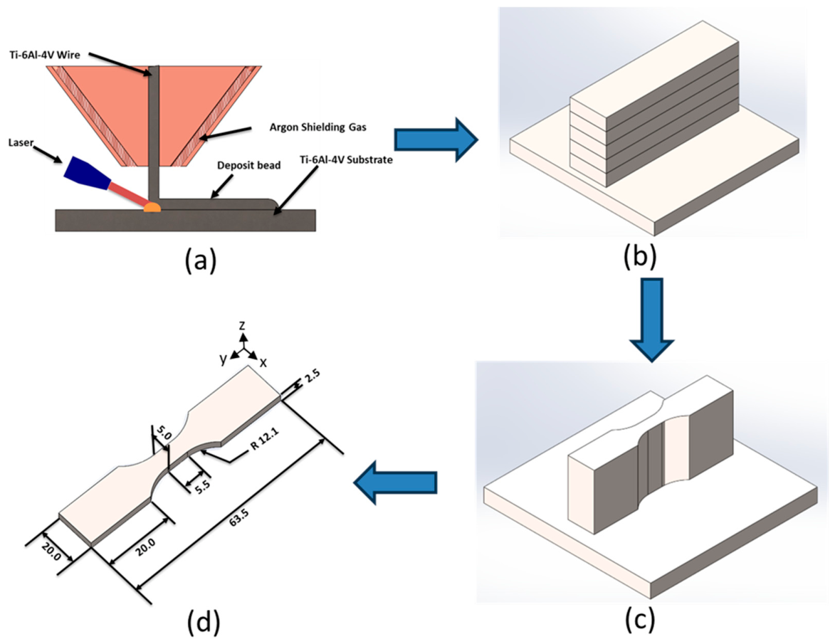
Figure 1. Hybrid AM/SM LW-DED manufacturing process used to manufacture test coupons, where (a) is the initial deposition process using LW-DED to deposit a layer of material onto a Ti-6Al-4V substrate, (b) is the layered deposited block consisting of multiple layers of LW-DED deposited material prior to CNC machining, (c) is the machined to the test coupon profile using CNC machining to create the near-net-shape geometry of the test coupon, and (d) is final test coupon geometry after being cut out using wire EDM and polished using 600-grit sandpaper to remove machining marks and limit surface defects.
Metals 16 00673 g001
Figure 2. Figure showing the (a) columnar grains observed in the resulting ASHM Ti-6Al-4V alloy through LW-DED with pores dispersed throughout the sample, and Vickers hardness plots corresponding to samples with measurements at the (b) top of the build and (c) bottom of the build, to show that the resulting micro-hardness has minimal variation throughout the build.
Metals 16 00673 g002
Table 1. Tensile results from each tensile test performed.
SampleYield Stress (MPa)UTS (MPa)Modulus (GPa)Elongation (%)
Build 1821.09950.54125.9320.77
Build 2811.34893.09118.7325.40
Build 3825.30962.95112.3416.92
Average819.24935.53119.0021.03
Table 2. Comparison of the ASHM Ti-6Al-4V tensile strength to other studies and wrought Ti-6Al-4V.
Material Manufacture MethodModulus
(GPa)
Yield Strength
(MPa)
Ultimate Tensile Strength (MPa)Elongation
(%)
Wrought Ti-6Al-4V [39]113.888095014.0
Cast Ti-6Al-4V [40]120.0784.8831.013.2
LW-DED Ti-6Al-4V [13]150.3759.8806.718.1
LW-DED ASHM Ti-6Al-4V [this study]119.00819.24935.5321.03
Table 3. Tabulated results of the fatigue tests with each build, stress value and cycles to failure.
Stress (MPa)Test No.Cycles to Failure
4001169,284
500172,092
500218,141
500354,252
600140,848
60025752
600313,702
70015967
70029532
70037588
8001772
80022447
8003505
Disclaimer/Publisher’s Note: The statements, opinions and data contained in all publications are solely those of the individual author(s) and contributor(s) and not of MDPI and/or the editor(s). MDPI and/or the editor(s) disclaim responsibility for any injury to people or property resulting from any ideas, methods, instructions or products referred to in the content.