Article

Investigating Fracture Behavior in Titanium Aluminides: Surface Roughness as an Indicator of Fracture Mechanisms in Ti-48Al-2Cr-2Nb Alloys

1
Department of Chemical, Materials and Industrial Production Engineering, University of Naples ‘Federico II’, 80125 Naples, Italy
2
Avio Aero S.r.l., Via G. Luraghi 20, 80038 Pomigliano D’Arco, Italy
*
Author to whom correspondence should be addressed.
Metals 2025, 15(1), 49; https://doi.org/10.3390/met15010049
Submission received: 28 November 2024 / Revised: 19 December 2024 / Accepted: 27 December 2024 / Published: 7 January 2025
(This article belongs to the Special Issue Research on Fatigue Behavior of Additively Manufactured Materials)

Abstract

:
Titanium aluminides, particularly the Ti-48Al-2Cr-2Nb alloy, have drawn significant attention for their potential in high-temperature aerospace and automotive applications due to their exceptional performances and reduced density compared to nickel-based superalloys. However, their intermetallic nature poses challenges such as limited room-temperature ductility and fracture toughness, limiting their widespread application. Additive manufacturing, specifically Electron Beam Melting (EBM), has emerged as a promising method for producing complex-shaped components of titanium aluminides, overcoming challenges associated with conventional production methods. This work investigates the fracture behavior of Ti-48Al-2Cr-2Nb specimens with different microstructures, including duplex and equiaxed, under tensile and high-cycle fatigue at elevated temperatures. Fracture surfaces were analyzed to distinguish between static and dynamic fracture modes. A novel method, employing confocal microscopy acquisitions, is proposed to correlate surface roughness parameters with the causes of failure, offering new insights into the fracture mechanisms of titanium aluminides. The results reveal significant differences in roughness values between the propagation and fracture zones for all the temperatures and microstructure tested. At 650 °C, the crack propagation zone exhibits lower Sq values than the fracture zone, with the fracture zone showing more pronounced roughness, particularly for the equiaxed microstructure. However, at 760 °C, the difference in Sq values between the propagation and fracture zones becomes more pronounced, with a more substantial increase in Sq values in the fracture zone. These findings contribute to understanding fracture behavior in titanium aluminides and provide a predictive framework for assessing structural integrity based on surface characteristics.

1. Introduction

The growing demand for efficient and eco-friendly energy systems has exposed the limitations of conventional metallic materials, which have nearly reached their performance boundaries after extensive development. Titanium aluminide alloys, based on the intermetallic phases γ (TiAl) and α2 (Ti3Al), are gaining attention for their exceptional properties, including high melting points (up to 1460 °C), low density (3.9–4.2 g/cm3), and excellent resistance to oxidation and corrosion [1,2]. These features position aluminides as potential replacements for heavier nickel and iron-based superalloys in automotive, gas turbine, and power plant applications, providing much higher specific properties [3]. Intermetallic alloys are characterized by a crystalline structure formed by combining two or more metallic elements, which occupy the points of a lattice in a periodic regular arrangement. These compounds exhibit a crystal lattice distinct from their constituent metals, existing as a single-phase solid that can also form solid solutions with the original metallic elements. The long-range atomic order in intermetallics persists up to a critical temperature (Tc), which in some cases can approach the melting temperature (Tm) of the compound [4,5].
Titanium alloys containing TiAl and Ti3Al phases are typically classified as either monophase (γ) or biphasic (α2 + γ) based on their composition. Although γ-TiAl alloys, known for their excellent high-temperature strength and oxidation resistance [6,7], were originally limited by low fracture toughness and room-temperature ductility, recent advancements in alloying and heat treatments have significantly improved their fracture performances and creep resistance, expanding their potential applications [8].
Microalloying elements such as Cr, Mn, V, and Nb play a crucial role in tailoring the properties of titanium aluminides. For instance, adding up to 2 at% of Cr, Mn, and V enhances ductility, while the addition of 1–2 at% Nb is necessary to achieve sufficient oxidation resistance [9,10]. Among biphasic alloys, the Ti-48Al-2Cr-2Nb intermetallic alloy is particularly notable for its exceptional properties, making it a key material in aerospace engine applications [11,12,13]. This alloy has been successfully employed in the construction of compressors, turbine casings, and intermediate turbine stage blades, where its high strength, oxidation resistance, and improved ductility are crucial for performance in high-temperature environments [14,15].
The mechanical properties of the aluminides are strongly influenced not only by the alloying elements but also by their microstructure. Four main microstructural types are observed: (i) a relatively coarse, fully lamellar structure (α2/γ colonies), (ii) a fine equiaxed structure (fine γ grains with α2 precipitates at grain boundaries), (iii) a fine duplex structure (a mixture of fine lamellar α2/γ and fine equiaxed grains), and (iv) a nearly lamellar structure (predominantly lamellar with some equiaxed γ grains) [16]. The duplex microstructure is particularly favored for structural applications due to its favorable combination of mechanical properties. This structure, which merges equiaxed and lamellar phases, enhances ductility through the interfaces between lamellar colonies and equiaxed grains [17,18,19,20].
The processing of titanium aluminides using conventional methods, such as casting and forging, is challenging due to the material’s low ductility and fracture resistance. Additive manufacturing (AM) technologies have emerged as a promising alternative, enabling the production of complex geometries with improved precision and material utilization [21,22].
Among powder bed AM technologies, Electron Beam Melting (EBM) is particularly suitable for producing titanium aluminide components. Unlike laser-based techniques, which may fail to meet preheating requirements and can introduce harmful thermal gradients, EBM employs a high-energy electron beam to melt metal powders layer by layer in a high-vacuum chamber. This process minimizes the risk of oxidation and ensures the production of dense components, particularly for reactive materials like titanium [23,24,25].
Despite the advantages offered by EBM and other advanced manufacturing techniques, the broader adoption of titanium aluminides is still hindered by the lack of understanding of their complex fracture behavior. These materials exhibit different fracture morphologies compared to conventional metals, particularly in fatigue failure, where crack propagation features such as striations are typically absent [26,27,28]. Therefore, it is challenging to understand the cause of failure from fracture surface observations.
Moreover, their mechanical response varies significantly across their operational range, transitioning from brittle to ductile behavior depending on temperature, further complicating failure analysis. A thorough understanding of the material’s response is essential not only for the direct application of titanium aluminide-based components but also for their subsequent processing, including welding and joining. In particular, intermetallic phases play a crucial role in the joining of dissimilar materials, as in techniques like diffusion bonding, where intermetallic phases are formed during the bonding process [29,30]. To ensure the integrity of the joined components, it is crucial to comprehend the characteristics of these intermetallic phases and their behavior within the joint.
To address these challenges, this study presents a novel method that employs confocal microscopy to characterize the fracture surface and establish a correlation between surface roughness parameters and the underlying causes of failure in Ti-48Al-2Cr-2Nb components. Specimens with duplex and equiaxed microstructures were analyzed, as these microstructures are known for their distinct mechanical properties. Destructive testing, including tensile tests to characterize static fracture surfaces and high-cycle fatigue (HCF) tests to analyze dynamic fracture surfaces, was performed at two distinct temperatures to capture both ductile and brittle fracture behaviors. Confocal microscopy was used to characterize the fracture surfaces and differentiate between initiation, propagation, and catastrophic fracture zones. Additionally, scanning electron microscopy (SEM) was employed to examine the microstructure of the specimens following fracture, providing a comprehensive understanding of the fracture mechanisms.

2. Materials and Methods

2.1. Production of Ti-48Al-2Cr-2Nb Specimens Through EBM Technology

Ti-48Al-2Cr-2Nb specimens used in this study were fabricated using Electron Beam Melting (EBM) additive manufacturing, followed by Hot Isostatic Pressing (HIP) treatment. The process parameters used for specimen production were those commonly referenced in the literature for the manufacturing of Ti-48Al-2Cr-2Nb components [24,31]. In particular, the beam current was set to 10 mA, and the scanning speed was adjusted to 600 mm/s. The specimens were printed using an Arcam A2X EBM machine (Arcam, Mölndal, Sweden).
For each type of destructive test to be analyzed, 10 specimens were produced for each microstructure under study. Specifically, 10 duplex microstructure specimens and 10 equiaxed microstructure specimens, each with a circular cross-section, were produced following the ASTM E21-20 [32] standard for high-temperature tensile testing. Similarly, 10 duplex and 10 equiaxed specimens were produced with a circular cross-section following the ASTM E606/E606M-21 [33] standard for HCF testing. After production, the EBM-fabricated material underwent HIP treatments to reduce or eliminate residual porosities. This treatment is particularly necessary to achieve high-performance components with duplex microstructures. The microstructure of the duplex samples following the HIP treatment is presented in Figure 1.
The specimens characterized by the equiaxed microstructure are composed of fine γ grains with α2 precipitates along the grain boundaries. This structure results from heat treatment at lower temperatures in the α2 + γ region of the Ti-Al binary phase diagram. The mean grain size of the equiaxed specimens is 21.44 ± 0.48 μm. The specimens with the duplex microstructure consist of a mixture of fine α2//γ lamellae and fine equiaxed γ grains, forming through heat treatment in the α + γ region. The mean γ-grain size is 14.19 ± 0.95 μm, while the lamellae dimension is 3.27 ± 0.70 μm.

2.2. Characterization of the Samples

As mentioned in previous sections, the characterization tests consisted of tensile and HCF tests. All tests were conducted at two distinct temperatures, 650 °C and 760 °C, chosen to span the brittleness and ductility ranges of the specimens, allowing for a comparative analysis of their behavior. The tensile tests were performed using a universal testing machine, and deformation was measured with an extensometer. Given that the tests were conducted at elevated temperatures, the ASTM E21-20 standard was followed.
Fatigue tests were performed using fatigue test equipment, with the number of cycles starting from 10,000 to ensure that failure occurred under significantly lower stresses than the material’s yield strength. In these tests, the applied stress was uniaxial and oriented along the specimen’s axis until failure occurred. The R-ratio, defined as the ratio of minimum to maximum stress (R = σmin/σmax), was set to 0.6 for the test. The frequency was set to 15 Hz, and the maximum stress was 300 MPa. After the mechanical tests, the fracture surfaces of the specimens were examined using a Scanning Electron Microscope (SEM), HITACHI TM3000 (Hitachi, Tokyo, Japan), to analyze the fracture patterns. Subsequently, to verify the existence of differences in the surface characteristics of the fracture surfaces obtained from the different tests, analyses were performed using a confocal microscope (Leica DCM3D Scan, Leica Microsystems, Wetzlar, Germany) in conjunction with LeicaMap processing software (version DCM 7.3.7746). The quantitative surface parameters evaluated included Sa (arithmetical mean height), and Sq (root mean square height). These two parameters were selected for their distinct characteristics in surface roughness analysis. Sa (arithmetical mean deviation of the surface) is defined as the arithmetic average of the absolute values of the surface height deviations from the mean plane. It provides a general indication of surface roughness and is less sensitive to extreme peaks and valleys. In contrast, Sq (root mean square roughness) is calculated as the square root of the average of the squared deviations of the surface heights from the mean plane. This parameter is more sensitive to larger peaks and valleys, offering a more detailed representation of the surface’s irregularities.
For the analysis, a Gaussian filter with a cutoff of 0.08 mm was applied to obtain the roughness surface, ensuring accurate measurement of the surface’s characteristics without the influence of high-frequency noise.

3. Results

3.1. Tensile Tests

Following static load tests conducted at temperatures both above and below the brittle-to-ductile transition temperature, the tensile properties of specimens with duplex and equiaxed microstructures were evaluated. The results showed that at 650 °C, the specimens with a duplex microstructure exhibited a UTS of 480 ± 10 MPa and an elongation at break of 2.2 ± 0.3%. At the same temperature, the equiaxed microstructure specimens demonstrated a higher UTS of 506 ± 12 MPa but a lower elongation at break of 1.5 ± 0.2%. At 760 °C, the duplex microstructure specimens showed a UTS of 472 ± 8 MPa and an elongation at break of 4.6 ± 0.4%, while the equiaxed microstructure specimens exhibited a UTS of 503 ± 8 MPa and an elongation at break of 2.8 ± 0.2%. These results are consistent with the existing literature, which indicates that duplex microstructures typically exhibit lower strength but greater ductility compared to equiaxed microstructures. The fracture surfaces were analyzed, and the tested specimens are shown in the macrographs presented in Figure 2.
For the specimen with a duplex microstructure, stereomicroscope observations revealed a clear distinction between fractures occurring above and below the ductile-to-brittle transition temperature during static loading.
The fracture surface of the specimen tested at 650 °C (Figure 2a) exhibits a distinctly faceted and shiny appearance, characteristic of cleavage morphology. In contrast, the surface of the specimen fractured at 760 °C (Figure 2b) is marked by a more porous and matte texture, which can be attributed not only to the ductile fracture morphology but also to oxidation. In fact, the increased exposure to the oxidizing atmosphere at elevated temperatures contributes to the darker appearance observed in this surface. These specimens display a ductile fracture morphology, with fracture surfaces exhibiting a fibrous appearance at the macroscopic level. This characteristic is attributed to the presence of micro-cavities, referred to as “dimples”, on the fracture surfaces. Furthermore, a reduction in the diameter of the fracture surface is observable, attributable to the necking phenomenon, as the material exhibits plastic deformation above the ductile-to-brittle transition temperature before failure.
Similarly, for specimens characterized by an equiaxed microstructure, the stereomicroscopic analysis reveals a clear demarcation between fractures that occurred above and below the ductile-to-brittle transition temperature. The surface of the specimen at 650 °C (Figure 2c) demonstrates a higher degree of brightness and faceting, whereas the surface of the specimen tested at 760 °C (Figure 2d) exhibits a more opaque appearance, characterized by the presence of dimples. Furthermore, in the specimens subjected to testing at 760 °C, as illustrated in Figure 3d, a notable reduction in the diameter of the fracture surface is observed, attributed to the necking phenomenon.
These findings are further corroborated by the analysis of the fracture surface images acquired via SEM, as presented in Figure 3. Higher magnification images in Figure 4 offer a more detailed examination of the fracture surfaces morphology.
In both cases, SEM analysis provides further confirmation of the previous observations, with distinct ductile and brittle fracture morphologies clearly identifiable. The ductile fracture displays a more porous structure with surface craters (dimples), while the brittle fracture is more faceted, exhibiting the characteristic features of cleavage.
However, it is not possible to conclusively determine whether the fracture mode is exclusively caused by the cleavage mechanism, and thus a purely transgranular fracture, which is more typical of ceramic materials. Titanium aluminides are intermetallic compounds, exhibiting properties that are characteristic of both metallic and ceramic materials. Specifically, for the duplex microstructure, which comprises both equiaxed and lamellar grains, it is challenging to definitively classify the fracture as either transgranular or intergranular.
Regarding the analysis of surface characteristics, Figure 5 provides examples of the roughness and waviness surfaces observed in duplex specimens after testing at 650 °C and 760 °C.
Visual analysis clearly shows that the surface of specimens fractured at higher temperatures features more pronounced peaks. Average key surface parameters were calculated from the roughness surfaces of the specimens and are presented in Table 1.

3.2. High-Cycle Fatigue Tests

The images of the fracture surfaces of the samples following the HCF tests are presented in Figure 6.
In both microstructures examined, clear distinctions can be observed between the initiation/propagation and fracture zones during HCF testing at 760 °C, a temperature at which the material exhibits increased ductility. At this temperature, the crack initiation and propagation zone shows extensive oxidation, evident from the distinct coloration in this portion of the material compared to the fracture zone (Figure 6b,d). In fact, since this zone is the first to reach fracture, it remains exposed to the oxidizing atmosphere for a longer duration.
To gain a more comprehensive understanding of the material’s behavior, it is essential to analyze the SEM micrographs presented in Figure 7. Higher-magnification images in Figure 8 are included to elucidate further fracture characteristics.
Upon analyzing the samples tested at 650 °C, both fracture surfaces clearly show the phenomenon of cleavage in the propagation zone. Similarly, in the fracture zone, the material also behaved in a brittle manner, with evident cleavage, although there are morphological differences between the two regions.
At 760 °C, the propagation zone also appears to have resulted from a brittle transgranular fracture, as the typical striations associated with ductile fracture are absent. However, in this case, the fracture zone exhibits a ductile morphology, similar to that seen in tensile tested specimens (Figure 4b,d). Specifically, dimples, characteristic of ductile fracture, can be observed. A distinct difference can be observed between the microstructures of the duplex and equiaxed specimens at the same analysis temperature. This is attributed to the fact that duplex microstructures exhibit characteristics of both lamellar and equiaxed microstructures.
Concerning the surface characteristic analysis, Figure 9 illustrates examples of the roughness and waviness observed on the surfaces of duplex specimens following testing at 650 and 760 °C.
From the visual analysis of the surface topography acquired through confocal microscopy, it is evident that the propagation and fracture zones, at both considered temperatures, exhibit significantly different average roughness values, allowing for a clear distinction between these regions. Notably, on the waviness surface, the typical fatigue striations are not visible. To quantitatively assess these differences across all tested sample types, the mean surface parameters were extracted from the roughness profiles and are presented in Table 2.

4. Discussion

The titanium aluminides examined exhibit morphological characteristics that distinguish them from conventional metallic materials, complicating the identification of the damage mechanisms and the understanding of fracture causes. Fracture typically initiates at the surface of the material, often due to surface irregularities such as microcracks and micro-notches. Even when the applied load is below the yield strength, localized stresses can exceed critical thresholds, triggering sliding phenomena. At the base of these surface irregularities, stresses are intensified due to the notch effect, making the material more susceptible to localized failure and the formation of microcracks. These microcracks tend to coalesce, forming a primary crack, which is then considered to be nucleated. The crack propagates initially along a 45° direction, subsequently continuing perpendicular to the applied stress direction. Following crack nucleation, its propagation typically occurs in a transgranular manner (characteristic of brittle fracture) and is oriented perpendicular to the direction of maximum applied stress, deviating from the initial 45° path. With each loading cycle, the crack progresses, occasionally leaving characteristic markings known as “striations”; however, these features are not discernible in the material under investigation. Stress intensification occurs at the crack tip, and if the material is sufficiently ductile, plastic deformation is observed, with crack propagation similar to that seen in ductile fracture. As the crack advances, the cross-sectional area of the material progressively diminishes. Once the cross-sectional area is sufficiently reduced and the crack reaches the critical section size, the final fracture occurs due to static overload. In the context of fatigue fracture, the two microstructures analyzed (duplex and equiaxed) exhibit distinct behaviors. The duplex microstructure, which consists of both equiaxed and lamellar grains, exhibits distinct fracture characteristics. According to the literature [34], in lamellar microstructures, fatigue cracks nucleate at weak points, such as pores, cavities, damaged surfaces, and oxide inclusions. However, it has been observed that lamellar colonies oriented perpendicular to the loading axis act as structural defects, as fatigue cracks tend to nucleate more easily in the interlamellar regions than within the lamellae themselves. Once the interlamellar crack initiates, it propagates rapidly. Additionally, some studies suggest that when the lamellar structure consists of lamellae larger than the critical crack size, their anisotropic properties govern the fatigue fracture behavior [35].
Having observed how lamellae oriented perpendicular to the loading axis act as defects and initiate crack propagation, the equiaxed region was investigated for comparison with the roughness values obtained from specimens with an equiaxed microstructure that failed due to static overload (below the ductile-to-brittle transition temperature, in line with the specimens under examination). The results substantiate the identification of this region as a failure zone, supporting the hypothesis that the lamellar region is where fracture is initiated and propagated. To facilitate a comparison between the two microstructures and to delineate the crack initiation and propagation zones, a comparison of the roughness values is presented in Figure 10.
Thus, guidelines can be established to predict the fracture mode of components made from titanium aluminides. To determine the origin of the fracture, it is essential to generate a height map of the component. By analyzing the height maps and assessing the roughness values in different regions, it can be inferred that areas with lower roughness are likely to correspond to the fracture initiation zones, regardless of whether the component operated above or below the ductile-to-brittle transition temperature.

5. Conclusions

This study examined the fracture behavior of Ti-48Al-2Cr-2Nb alloy by analyzing the fracture surfaces resulting from tensile and HCF tests, employing confocal microscopy. The investigation focused on two distinct microstructures (equiaxed and duplex) at elevated temperatures (650 °C and 760 °C) to elucidate the transition between brittle and ductile fracture modes, providing deeper insights into the alloy’s mechanical performance under varying conditions. The following conclusions can be drawn from the results:
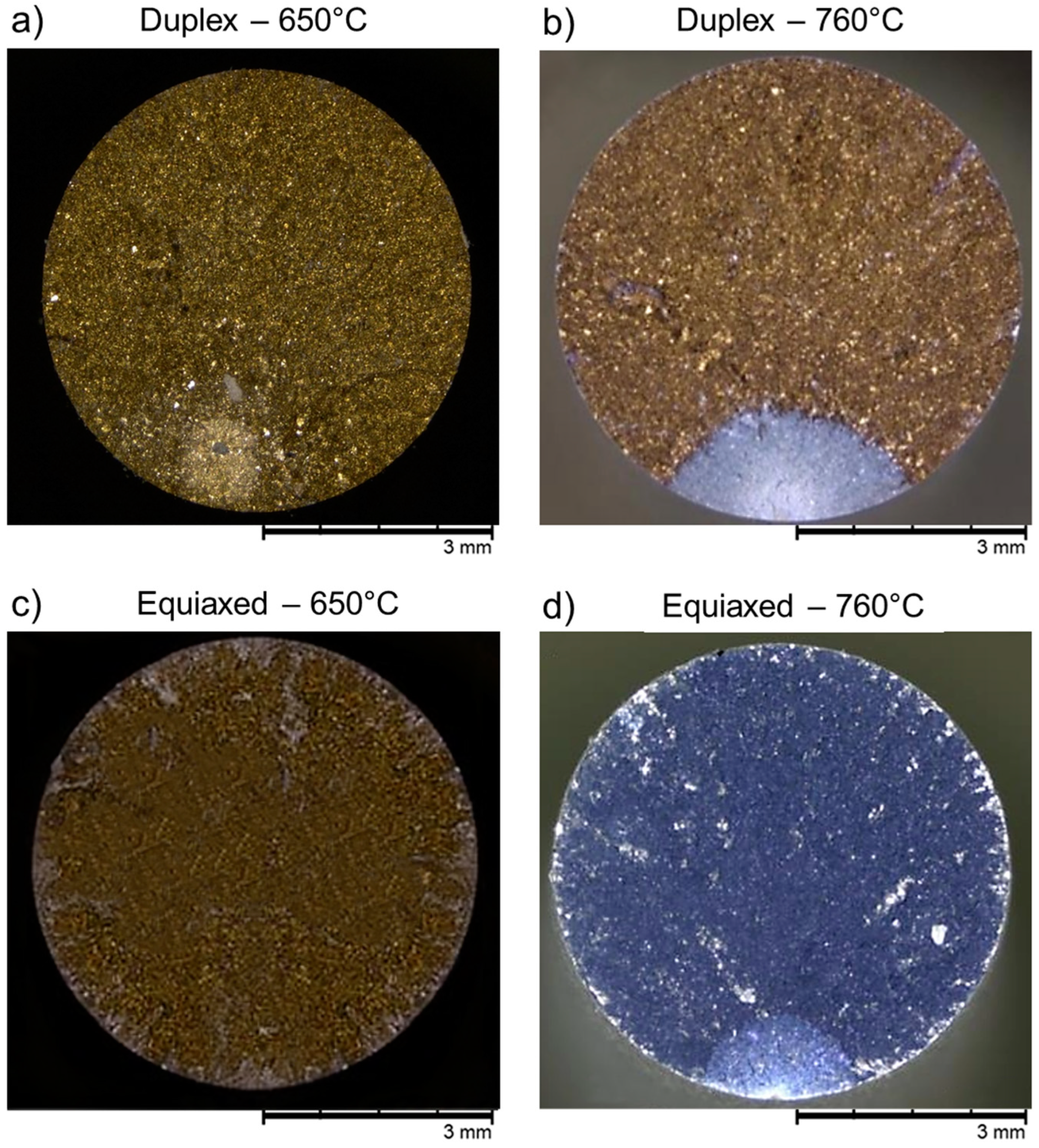
  • Fracture behavior of Ti-48Al-2Cr-2Nb alloy was highly influenced by both the microstructure and testing temperature, with notable differences between the duplex and equiaxed microstructures under varying loading conditions.
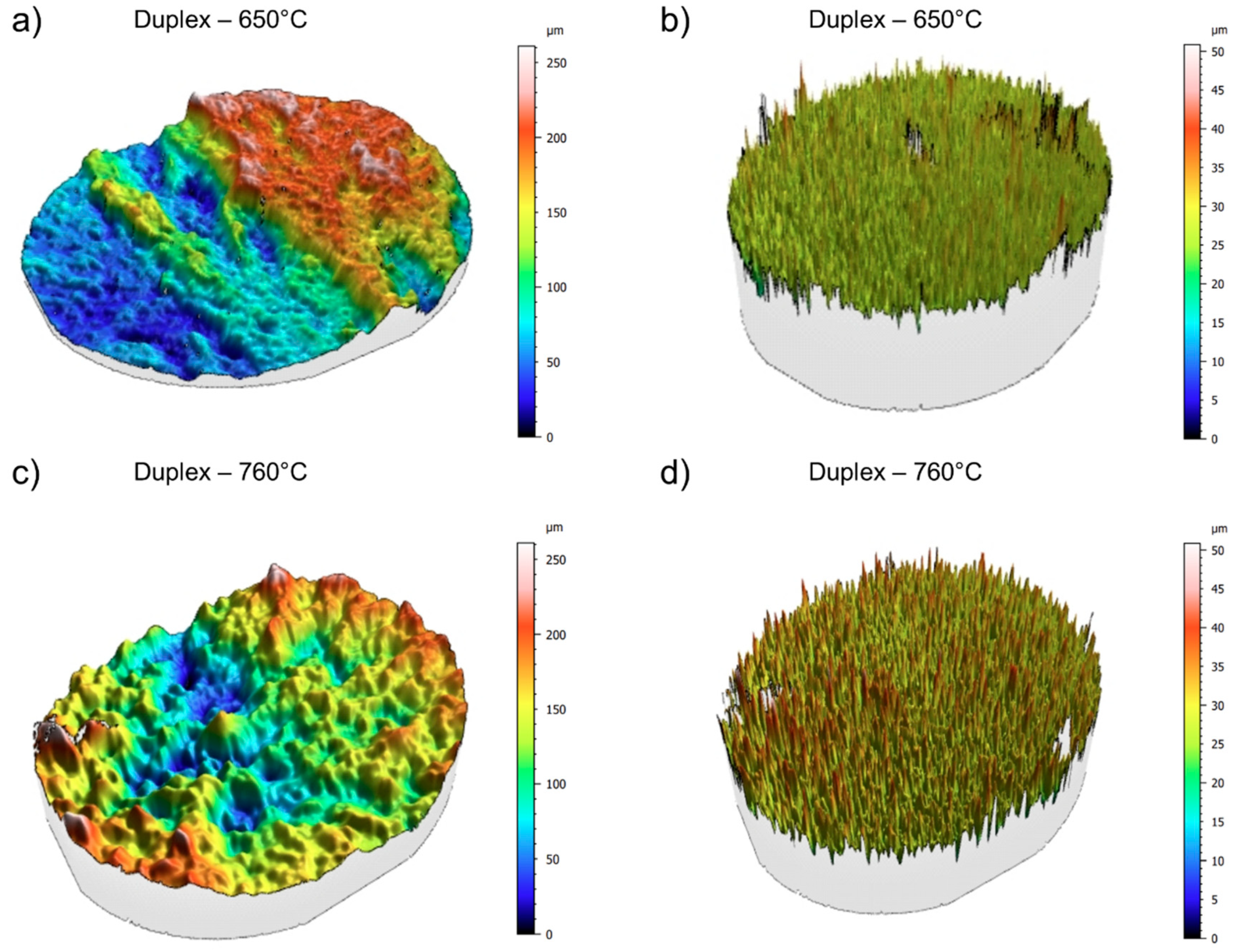
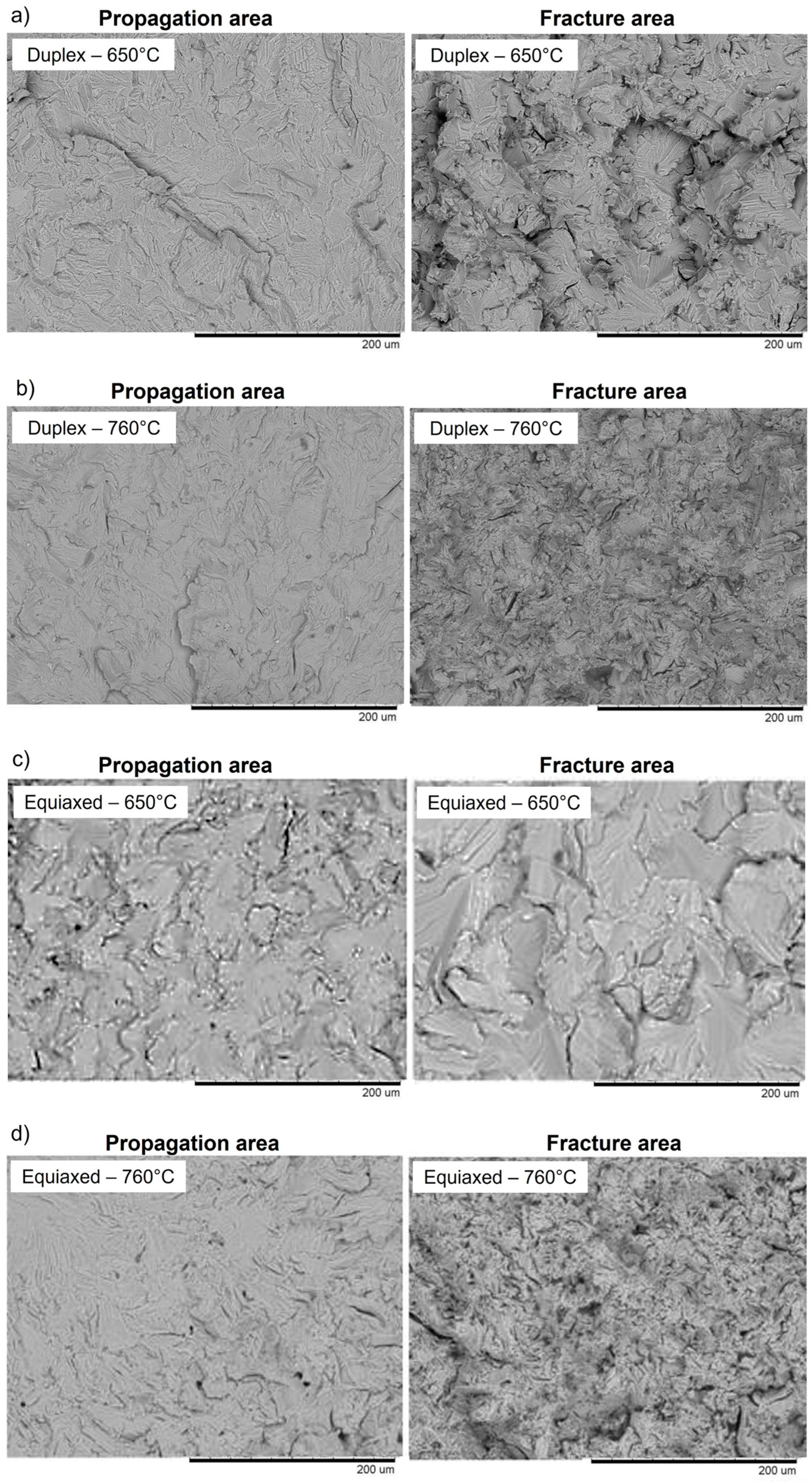
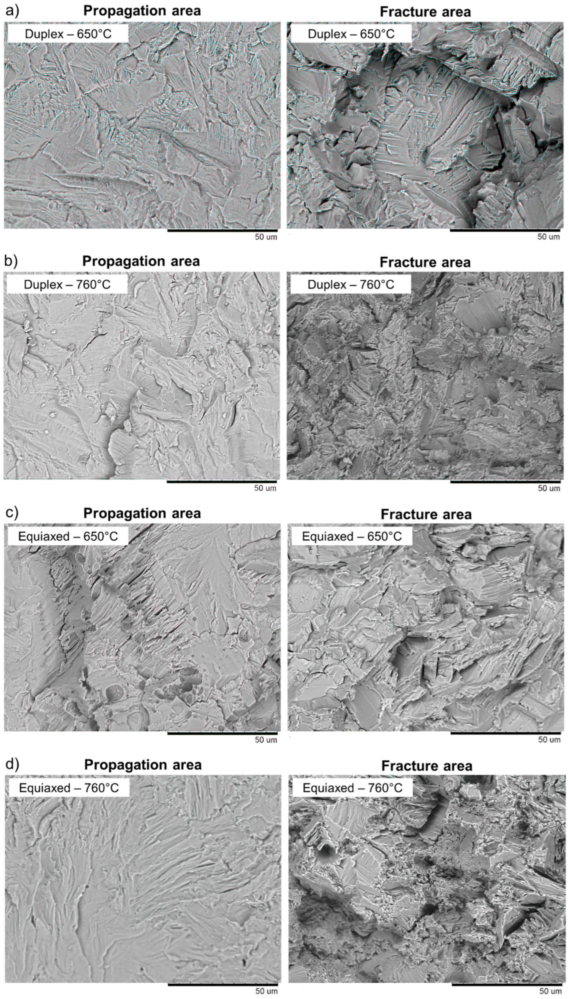
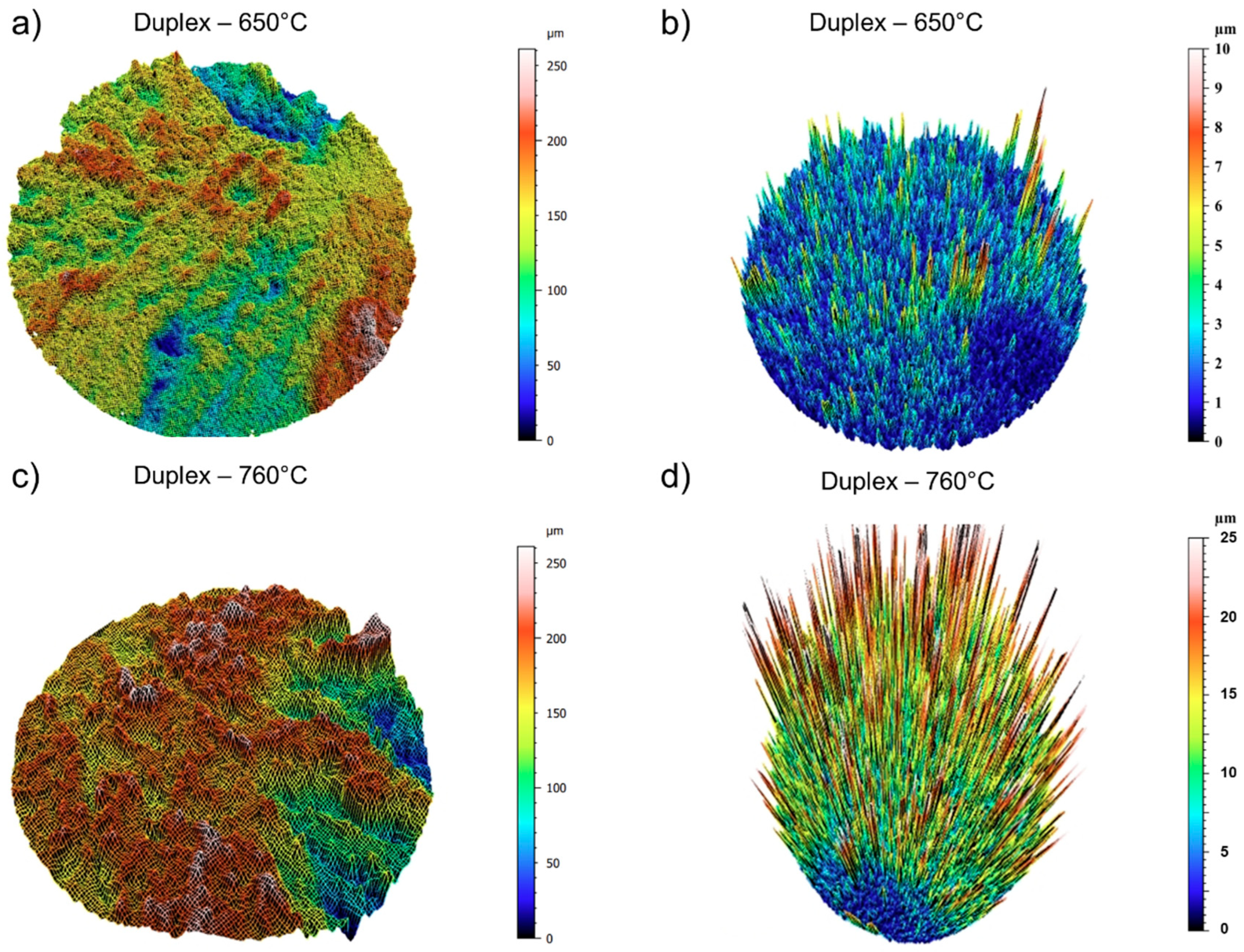
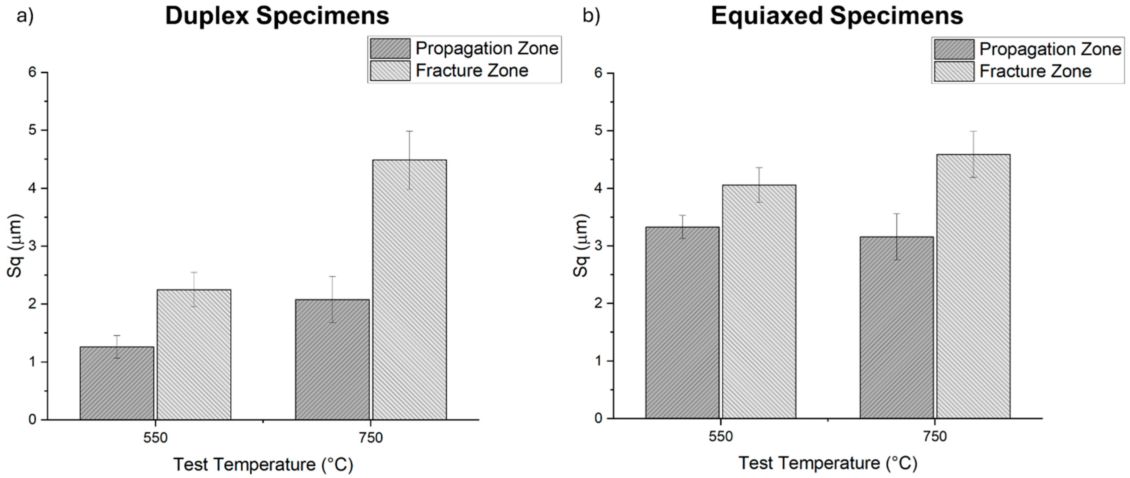
  • Surface roughness was found to be a critical indicator of fracture mechanisms. The propagation zone in both tested temperatures (650 °C and 760 °C) exhibited lower Sq values, indicating brittle fracture behavior. This was consistent with the reduced surface roughness observed in this region, which suggests limited plastic deformation before fracture.
  • At 650 °C, the equiaxed microstructure demonstrated a less pronounced difference in Sq values between the propagation and fracture zones compared to the duplex microstructure, indicating the influence of the hybrid lamellar-equiaxed microstructure of the duplex specimens. At 760 °C, the fracture zone showed considerably higher Sq values than the propagation zone, due to the more ductile behavior in the fracture zone. This aligns with the higher temperature promoting increased plasticity and more significant deformation before final failure.
  • A reliable method for evaluating the fracture behavior of titanium aluminide components can be developed through the construction of surface height maps generated via confocal microscopy. Analysis of roughness values across these maps reveals that regions with lower roughness consistently correspond to fracture initiation and propagation zones, regardless of whether the material operates above or below the ductile-to-brittle transition temperature.
These findings provide a deeper understanding of fracture mechanisms in titanium aluminides, demonstrating the effectiveness of confocal microscopy for detailed surface inspection and surface roughness analysis.

Author Contributions

Conceptualization, L.S. and F.S.; Methodology, L.S. and F.S.; Investigation, A.S.P., L.S. and F.S.; Resources, M.C.; Writing—original draft, A.S.P.; Project administration, M.C. All authors have read and agreed to the published version of the manuscript.

Funding

This research received no external funding.

Data Availability Statement

The original contributions presented in the study are included in the article, further inquiries can be directed to the corresponding author.

Conflicts of Interest

Authors Lorenzo Savio and Michele Coppola were employed by the company Avio Aero S.r.l. The remaining authors declare that the research was conducted in the absence of any commercial or financial relationships that could be construed as a potential conflict of interest.

References

  1. Huang, S.; Lin, Y.-C.; Chung, R.-J. A Review of the State of Art of Fabrication Technologies of Titanium Aluminide (Ti-Al) Based on US Patents. Metals 2024, 14, 418. [Google Scholar] [CrossRef]
  2. Wimler, D.; Lindemann, J.; Reith, M.; Kirchner, A.; Allen, M.; Vargas, W.G.; Franke, M.; Klöden, B.; Weißgärber, T.; Güther, V.; et al. Designing Advanced Intermetallic Titanium Aluminide Alloys for Additive Manufacturing. Intermetallics 2021, 131, 107109. [Google Scholar] [CrossRef]
  3. Anil Kumar, V.; Gupta, R.K.; Prasad, M.J.N.V.; Narayana Murty, S.V.S. Recent Advances in Processing of Titanium Alloys and Titanium Aluminides for Space Applications: A Review. J. Mater. Res. 2021, 36, 689–716. [Google Scholar] [CrossRef]
  4. Sauthoff, G. Intermetallics; Wiley: Hoboken, NJ, USA, 1995; ISBN 9783527268214. [Google Scholar]
  5. Djanarthany, S.; Viala, J.-C.; Bouix, J. An Overview of Monolithic Titanium Aluminides Based on Ti3Al and TiAl. Mater. Chem. Phys. 2001, 72, 301–319. [Google Scholar] [CrossRef]
  6. Clemens, H.; Mayer, S. Intermetallic Titanium Aluminides in Aerospace Applications—Processing, Microstructure and Properties. Mater. High Temp. 2016, 33, 560–570. [Google Scholar] [CrossRef]
  7. Clemens, H.; Mayer, S. Design, Processing, Microstructure, Properties, and Applications of Advanced Intermetallic TiAl Alloys. Adv. Eng. Mater. 2013, 15, 191–215. [Google Scholar] [CrossRef]
  8. Subramanian, P.R.; Mendiratta, M.G.; Dimiduk, D.M.; Stucke, M.A. Advanced Intermetallic Alloys—Beyond Gamma Titanium Aluminides. Mater. Sci. Eng. A 1997, 239–240, 1–13. [Google Scholar] [CrossRef]
  9. Gupta, R.K.; Pant, B.; Agarwala, V.; Sinha, P.P. Effect of Chromium and Niobium on the Kinetics of Synthesis of Titanium Aluminide. Met. Sci. Heat Treat. 2013, 55, 438–444. [Google Scholar] [CrossRef]
  10. Tlotleng, M.; Pityana, S.; Motha, S. Insights on Niobium Micro-Alloyed Laser In Situ Synthesised Gamma Titanium Aluminide Alloys. Appl. Sci. 2023, 13, 5725. [Google Scholar] [CrossRef]
  11. Seifi, M.; Ghamarian, I.; Samimi, P.; Ackelid, U.; Collins, P.; Lewandowski, J. Microstructure and Mechanical Properties of Ti-48Al-2Cr-2Nb Manufactured via Electron Beam Melting. In Proceedings of the 13th World Conference on Titanium; Wiley: Hoboken, NJ, USA, 2016; pp. 1317–1322. [Google Scholar]
  12. Liu, Z.; Wang, C.; Wang, W.; Xu, G.; Liu, X. Effects of Tantalum on the Microstructure and Properties of Ti-48Al-2Cr-2Nb Alloy Fabricated via Laser Additive Manufacturing. Mater. Charact. 2021, 179, 111317. [Google Scholar] [CrossRef]
  13. Mizuta, K.; Hijikata, Y.; Fujii, T.; Gokan, K.; Kakehi, K. Characterization of Ti-48Al-2Cr-2Nb Built by Selective Laser Melting. Scr. Mater. 2021, 203, 114107. [Google Scholar] [CrossRef]
  14. Mengis, L.; Grimme, C.; Galetz, M.C. Tribological Properties of the Uncoated and Aluminized Ti–48Al–2Cr–2Nb TiAl Alloy at High Temperatures. Wear 2021, 477, 203818. [Google Scholar] [CrossRef]
  15. Hernandez, J.; Murr, L.E.; Gaytan, S.M.; Martinez, E.; Medina, F.; Wicker, R.B. Microstructures for Two-Phase Gamma Titanium Aluminide Fabricated by Electron Beam Melting. Metallogr. Microstruct. Anal. 2012, 1, 14–27. [Google Scholar] [CrossRef]
  16. Kuang, J.P.; Harding, R.A.; Campbell, J. Microstructures and Properties of Investment Castings of γ-Titanium Aluminide. Mater. Sci. Eng. A 2002, 329–331, 31–37. [Google Scholar] [CrossRef]
  17. Gupta, R.K.; Pant, B. Titanium Aluminides. In Intermetallic Matrix Composites; Elsevier: Amsterdam, The Netherlands, 2018; pp. 71–93. [Google Scholar]
  18. Dahar, M.S.; Seifi, S.M.; Bewlay, B.P.; Lewandowski, J.J. Effects of Test Orientation on Fracture and Fatigue Crack Growth Behavior of Third Generation As-Cast Ti–48Al–2Nb–2Cr. Intermetallics 2015, 57, 73–82. [Google Scholar] [CrossRef]
  19. Genc, O.; Unal, R. Development of Gamma Titanium Aluminide (γ-TiAl) Alloys: A Review. J. Alloys Compd. 2022, 929, 167262. [Google Scholar] [CrossRef]
  20. Liu, Z.C.; Lin, J.P.; Li, S.J.; Chen, G.L. Effects of Nb and Al on the Microstructures and Mechanical Properties of High Nb Containing TiAl Base Alloys. Intermetallics 2002, 10, 653–659. [Google Scholar] [CrossRef]
  21. Feng, J.; Gui, W.; Liu, Q.; Bi, W.; Ren, X.; Liang, Y.; Lin, J.; Luan, B. Ti–48Al–2Cr–2Nb Alloys Prepared by Electron Beam Selective Melting Additive Manufacturing: Microstructural and Tensile Properties. J. Mater. Res. Technol. 2023, 26, 9357–9369. [Google Scholar] [CrossRef]
  22. Soliman, H.A.; Elbestawi, M. Titanium Aluminides Processing by Additive Manufacturing—A Review. Int. J. Adv. Manuf. Technol. 2022, 119, 5583–5614. [Google Scholar] [CrossRef]
  23. Behjat, A.; Saboori, A.; Galati, M.; Iuliano, L. The Electrochemical Behaviour of Ti-48Al-2Cr-2Nb Produced by Electron Beam Powder Bed Fusion Process. Intermetallics 2024, 175, 108472. [Google Scholar] [CrossRef]
  24. Lin, B.; Chen, W.; Yang, Y.; Wu, F.; Li, Z. Anisotropy of Microstructure and Tensile Properties of Ti–48Al–2Cr–2Nb Fabricated by Electron Beam Melting. J. Alloys Compd. 2020, 830, 154684. [Google Scholar] [CrossRef]
  25. Emiralioğlu, A.; Ünal, R. Additive Manufacturing of Gamma Titanium Aluminide Alloys: A Review. J. Mater. Sci. 2022, 57, 4441–4466. [Google Scholar] [CrossRef]
  26. Dahar, M.S.; Tamirisakandala, S.A.; Lewandowski, J.J. Evolution of Fatigue Crack Growth and Fracture Behavior in Gamma Titanium Aluminide Ti-43.5Al-4Nb-1Mo-0.1B (TNM) Forgings. Int. J. Fatigue 2018, 111, 54–69. [Google Scholar] [CrossRef]
  27. Trant, C.F.; Lindley, T.C.; Martin, N.; Dixon, M.; Dye, D. Fatigue Cracking in Gamma Titanium Aluminide. Mater. Sci. Eng. A 2020, 798, 140202. [Google Scholar] [CrossRef]
  28. Davidson, D.L.; Campbell, J.B.; Page, R.A. The Initiation and Growth of Fatigue Cracks in a Titanium Aluminide Alloy. Metall. Trans. A 1991, 22, 377–391. [Google Scholar] [CrossRef]
  29. Assari, A.H.; Eghbali, B. Microstructure and Kinetics of Intermetallic Phase Formation During Solid State Diffusion Bonding in Bimetal Ti/Al. Phys. Met. Metallogr. 2019, 120, 260–268. [Google Scholar] [CrossRef]
  30. AlHazaa, A.; Haneklaus, N. Diffusion Bonding and Transient Liquid Phase (TLP) Bonding of Type 304 and 316 Austenitic Stainless Steel—A Review of Similar and Dissimilar Material Joints. Metals 2020, 10, 613. [Google Scholar] [CrossRef]
  31. Murr, L.E.; Gaytan, S.M.; Ceylan, A.; Martinez, E.; Martinez, J.L.; Hernandez, D.H.; Machado, B.I.; Ramirez, D.A.; Medina, F.; Collins, S.; et al. Characterization of Titanium Aluminide Alloy Components Fabricated by Additive Manufacturing Using Electron Beam Melting. Acta Mater. 2010, 58, 1887–1894. [Google Scholar] [CrossRef]
  32. ASTM E21-20; Standard Test Methods for Elevated Temperature Tension Tests of Metallic Materials. ASTM: West Conshohocken, PA, USA, 2021.
  33. ASTM E606/E606M-21; Standard Test Method for Strain-Controlled Fatigue Testing. ASTM: West Conshohocken, PA, USA, 2021.
  34. Ellard, J.J.M.; Mathabathe, M.N.; Siyasiya, C.W.; Bolokang, A.S. Low-Cycle Fatigue Behaviour of Titanium-Aluminium-Based Intermetallic Alloys: A Short Review. Metals 2023, 13, 1491. [Google Scholar] [CrossRef]
  35. Leyens, C.; Peters, M. (Eds.) Titanium and Titanium Alloys; Wiley: Hoboken, NJ, USA, 2003; ISBN 9783527305346. [Google Scholar]
Figure 1. SEM images of the microstructure of specimens obtained via EBM technology and subjected to HIP treatment characterized by of (a) equiaxed microstructure (b) duplex microstructure.
Metals 15 00049 g001
Figure 2. Stereomicroscope images of the specimens subjected to tensile tests characterized by: (a) duplex microstructure tested at 650 °C; (b) duplex microstructure tested at 760 °C; (c) equiaxial microstructure tested at 650 °C; (d) equiaxed microstructure tested at 760 °C.
Metals 15 00049 g002
Figure 3. Comparison of fracture surfaces at 500× magnification, following tensile testing for specimens characterized by: (a) duplex microstructure tested at 650 °C; (b) duplex microstructure tested at 760 °C; (c) equiaxed microstructure tested at 650 °C; (d) equiaxed microstructure tested at 760 °C.
Metals 15 00049 g003
Figure 4. Comparison of fracture surfaces at 1500× magnification, following tensile testing for specimens characterized by: (a) duplex microstructure tested at 650 °C; (b) duplex microstructure tested at 760 °C; (c) equiaxed microstructure tested at 650 °C; (d) equiaxed microstructure tested at 760 °C.
Metals 15 00049 g004
Figure 5. Confocal acquisition of fracture surfaces of specimens after tensile testing: (a) Waviness surface of a duplex specimen at 650 °C; (b) Roughness surface of a duplex specimen at 650 °C; (c) Waviness surface of a duplex specimen at 760 °C; (d) Roughness surface of a duplex specimen at 760 °C.
Metals 15 00049 g005
Figure 6. Stereomicroscope images of the specimens subjected to HCF tests characterized by: (a) duplex microstructure tested at 650 °C; (b) duplex microstructure tested at 760 °C; (c) equiaxed microstructure tested at 650 °C; (d) equiaxed microstructure tested at 760 °C.
Metals 15 00049 g006
Figure 7. Comparison of fracture surfaces at 500× magnification, following HCF tests for specimens characterized by: (a) duplex microstructure tested at 650 °C; (b) duplex microstructure tested at 760 °C; (c) equiaxed microstructure tested at 650 °C; (d) equiaxed microstructure tested at 760 °C.
Metals 15 00049 g007
Figure 8. Comparison of fracture surfaces at 1500× magnification, following HCF tests for specimens characterized by: (a) duplex microstructure tested at 650 °C; (b) duplex microstructure tested at 760 °C; (c) equiaxed microstructure tested at 650 °C; (d) equiaxed microstructure tested at 760 °C.
Metals 15 00049 g008
Figure 9. Confocal acquisition of fracture surfaces of specimens after HCF testing: (a) Waviness surface of a duplex specimen at 650 °C; (b) Roughness surface of a duplex specimen at 650 °C; (c) Waviness surface of a duplex specimen at 760 °C; (d) Roughness surface of a duplex specimen at 760 °C.
Metals 15 00049 g009
Figure 10. Comparison of surface roughness values (Sq) for the propagation and fracture zones of specimens tested for HCF at 650 °C and 760 °C: (a) specimens with a duplex microstructure; (b) specimens with an equiaxed microstructure.
Metals 15 00049 g010
Table 1. Average roughness parameters (Sa and Sq) derived from the fracture surfaces of the specimens following tensile testing.
Sa [μm]Sq [μm]
Duplex T = 6502.01 ± 0.32.65 ± 0.3
Duplex T = 7603.12 ± 0.23.98 ± 0.4
Equiaxed T = 6504.16 ± 0.25.37 ± 0.8
Equiaxed T = 7604.42 ± 0.37.87 ± 0.7
Table 2. Average roughness parameters (Sa and Sq) derived from the fracture surfaces of the specimens following HCF testing.
Propagation Zone
Sa [μm]Sq [μm]
Duplex T = 6500.973 ± 0.11.26 ± 0.2
Duplex T = 7601.63 ± 0.22.08 ± 0.4
Equiaxed T = 6502.33 ± 0.33.33 ± 0.2
Equiaxed T = 7602.43 ± 0.33.16 ± 0.4
Fracture Zone
Sa [μm]Sq [μm]
Duplex T = 6501.68 ± 0.22.25 ± 0.3
Duplex T = 7603.30 ± 0.34.49 ± 0.5
Equiaxed T = 6502.49 ± 0.34.06 ± 0.3
Equiaxed T = 7603.58 ± 0.24.59 ± 0.4
Disclaimer/Publisher’s Note: The statements, opinions and data contained in all publications are solely those of the individual author(s) and contributor(s) and not of MDPI and/or the editor(s). MDPI and/or the editor(s) disclaim responsibility for any injury to people or property resulting from any ideas, methods, instructions or products referred to in the content.

