Article

Fatigue Crack Propagation in a High-Pressure Turbine Blade Slot Damaged by Fretting

by
Hamad Alarfati
1,
Gordana Kastratović
2,
Aleksandar Grbović
1,
Martina Balać
1,* and
Nenad Vidanović
2
1
Faculty of Mechanical Engineering, University of Belgrade, Kraljice Marije 16, 11000 Belgrade, Serbia
2
Faculty of Transport and Traffic Engineering, University of Belgrade, Vojvode Stepe 305, 11000 Belgrade, Serbia
*
Author to whom correspondence should be addressed.
Metals 2026, 16(6), 564; https://doi.org/10.3390/met16060564
Submission received: 10 March 2026 / Revised: 12 May 2026 / Accepted: 19 May 2026 / Published: 22 May 2026
(This article belongs to the Special Issue Fracture Mechanics and Failure Analysis of Metallic Materials)

Abstract

In this study, fatigue crack propagation due to unexpected damage caused by fretting in an aero engine high-pressure turbine (HPT) blade slot is analyzed. Two different numerical crack models were applied and studied to simulate fatigue crack propagation caused by amplitude service loading. Also, the goal was to demonstrate the capacities of numerical simulations, including their limitations, especially when the crack propagation behavior should be predicted for critical parts of the real structure. It is shown that the structural integrity of the analyzed component is not jeopardized by the existing damage.

1. Introduction

The high-pressure turbine (HPT) rotor disk is a critical component of an aircraft engine, which is connected to the shaft and contains the slots where the turbine blades are attached. By rotating at high speed, it converts thermal energy from hot gas into mechanical energy to drive the high-pressure compressor and other engine systems. It is made from super alloys which can endure extreme operating conditions such as high temperatures, corrosive environments and mechanical stresses. As a rotating part of aircraft engine assembly, the HPT rotor disk represents, among other important components, the safety-critical structural component, which is exposed to complex cyclic loads during its operation. Hence, it is considered a safe-life part, which means that it is designed, manufactured, and maintained to have a specific service life (in flight cycles or hours) and must be removed from service before any unsafe condition, like crack initiation, can develop. However, due to the stochastic nature of in-service loads, machining damage, material aging, fretting, etc., fatigue crack initiation during that predicted “safe life” is possible [1]. Bearing in mind that the age of aircraft in operation worldwide is increasing, fatigue crack initiation and propagation in aircraft engine components is inevitable, as accepted by the life-time concept, involving structural integrity and life assessment.
One of the main causes of crack initiation in HPT rotor disks is fretting fatigue [2]. It is a challenging issue in engineering, particularly in rotating components (turbine blades, disks, shafts) where parts are in contact during operation and subject to vibrations, oscillations, and cyclic loading [3]. Dovetail slot attachments used for blade–disk assemblies in aero-engine compressors or turbines are particularly exposed to fretting fatigue [4,5]. The combination of design improvements, material enhancement, advanced coatings, and the integration of numerical simulations plays a crucial role in mitigating this problem and improving the safety and reliability of critical components.
Studies [6,7,8] improved the understanding and prediction of fretting fatigue, enabling better design, optimization, and maintenance practices for aerospace components. Fretting fatigue is a complex phenomenon affected by different factors such as temperature, load, friction coefficient, arc radius, etc. The effect of disk speed, contact angle, and coefficient of friction (COF) on the fretting responses of an aero-engine fir tree blade–disk assembly was presented in [6]. Enright et al. have shown that assessing fretting fatigue in military aircraft engine disks focuses on fracture risk reduction through non-destructive inspections and stress modeling [7]. The fretting fatigue behavior of dovetail attachments in aircraft engine fans is discussed, focusing on crack initiation and propagation under varying conditions of COF [8], where a fracture mechanics-based methodology was used to obtain a representative value of COF between the dovetail fan blade and hub. An investigation of the friction and wear behavior of the Inconel 718 superalloy and an analysis of the COF at different temperatures are presented in [9]. The authors concluded that the COF decreases as the temperature increases; the friction stabilizes faster due to the material softening and forming an oxide layer that acts as a lubricant, reducing wear.
Sun et al. investigated the impact of high temperatures on the fretting fatigue of aero-engine compressor dovetail structures [10]. They developed a high-temperature fretting fatigue life prediction model and proposed a criterion for crack initiation, validated through tests conducted at both room and elevated temperatures. The development of a fretting fatigue life prediction model for aero-engine dovetail structures by incorporating plastic deformation effects is presented in [11]. The FEM was used to identify critical stress zones and validate the model, while experiments with strain monitoring confirmed crack initiation points. Lindley and Nix analyzed the failure of a 660 MW turbine generator rotor due to fatigue cracking [12]. They investigated the causes and mechanisms of crack propagation to understand and solve the problem using computational stress analysis and numerical methods available at the time of their study. The crack initiated and propagated due to fretting fatigue on the rotor tooth contact surface near the gap between the longitudinal stiffness compensation wedges.
Wang et al. experimentally examined the fretting fatigue behavior of dovetail tenon and dovetail slot specimens based on a certain type of aeroengine with and without shot-peening treatment, focusing on crack initiation and propagation mechanisms, and shot-peening micro-structural modifications [13]. Studies [14,15] combined experimental and numerical methods to assess fretting fatigue on dovetail joint specimens.
All these studies also have in common that fretting damage occurred in known and expected locations. When damage appears where expected, maintenance procedures are available, but for unexpected damage, there are no such procedures. Thus, a dilemma arises: can the damaged component be returned to use (if it seems that the damage is not significant), or must it be replaced? It is obvious that in these cases, an evaluation of the structural integrity of the damaged part is necessary.
The answer to this question can be given most precisely by experiments, but they are time-consuming and expensive, and even impossible to perform when the damage is located on the “safe-life” part. Therefore, as a suitable alternative to experimental verification, numerical modeling is imposed. Thus, the use of numerical methods seems inevitable in cases like these.
Nowadays, the finite element method (FEM) and the extended finite element method (XFEM) are the most used for fatigue crack propagation modeling [16,17,18,19,20,21,22,23,24,25], including the moving mesh technique [26]. To overcome problems of FEM application in the crack propagation analysis (remeshing of the entire model for each new crack size), so-called Separating, Morphing, Adaptive, and Remeshing Technology (SMART) was introduced recently [27]. Although still being quite new, this “improved” FEM has been successfully applied in several studies [28,29,30,31,32,33,34,35].
The problem analyzed in this paper is not covered in the literature since it is very specific: the damage caused by fretting occurred during the operation, due to unpredictable loading for a limited period of time. The cause of the unpredictable loading was eliminated. Since the damaged part is very expensive, and its replacement would take quite a long time, during which the aircraft is not operational, the option of returning it to service was taken into consideration. If returned, the damaged part would continue to be exposed to the anticipated thermo-mechanical cyclic loading. In order to assess its structural integrity and to establish whether the damage that occurred was within serviceable limits, a numerical study of the eventual fatigue crack propagation emanating from the damage caused by unpredicted fretting in an aero engine HPT rotor disk blade slot was conducted. All simulations and calculations were conducted using the SMART feature of ANSYS Workbench software Release 25 [27], including the newest option—the Crack Initiation Feature (CIF).

2. Damage in the HPT Blade Slot

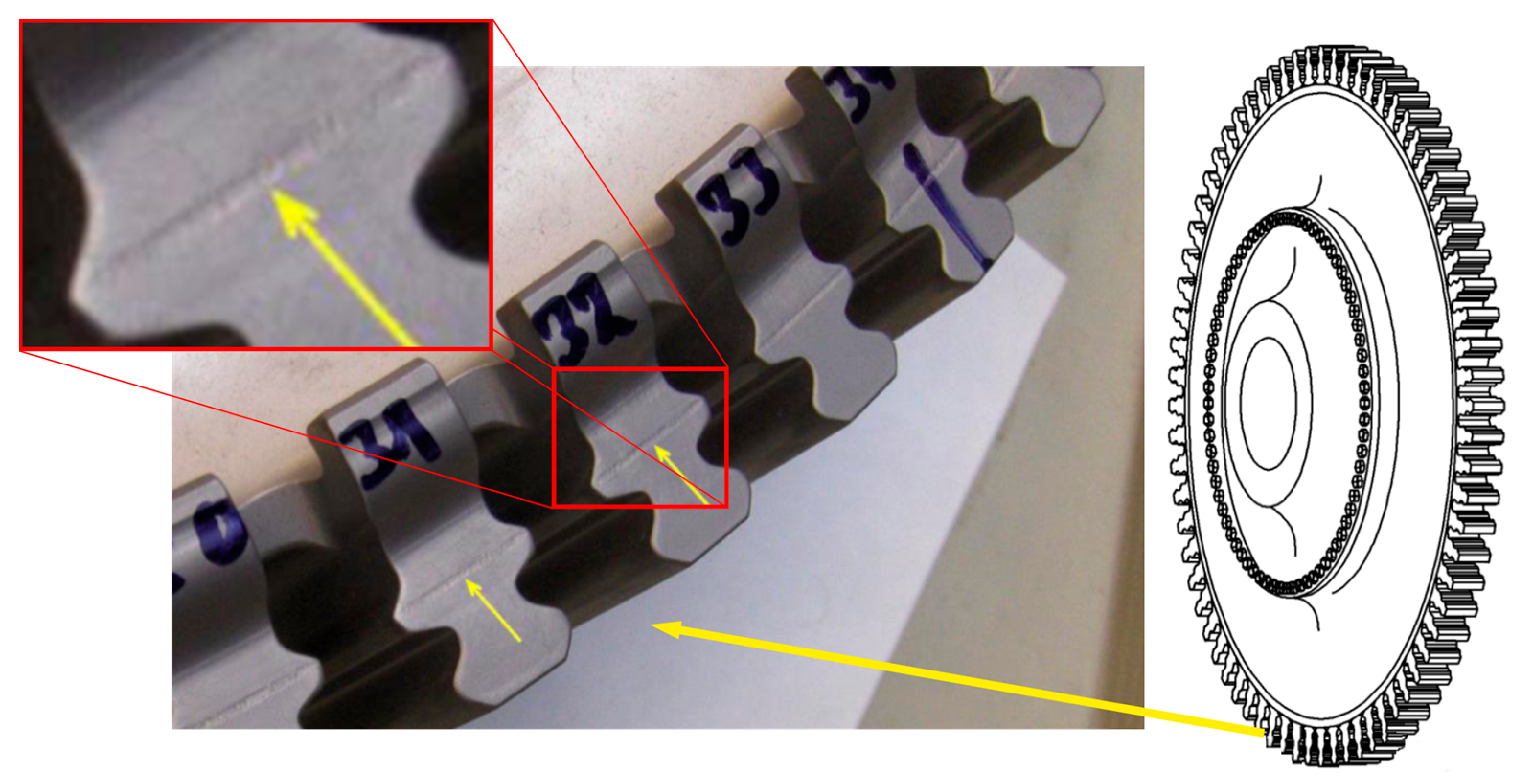
During the regular engine maintenance in the workshop, damage was observed on the teeth of the high-pressure turbine (HPT) rotor disk in an unexpected position (arrows in Figure 1), which was referred to as “the fretting path” by the Maintenance, Repair, and Operations (MRO) company. The HPT rotor disk is made of Inconel 718 and is a part of the aircraft turbofan engine, which powers modern commercial narrow-body airplanes.
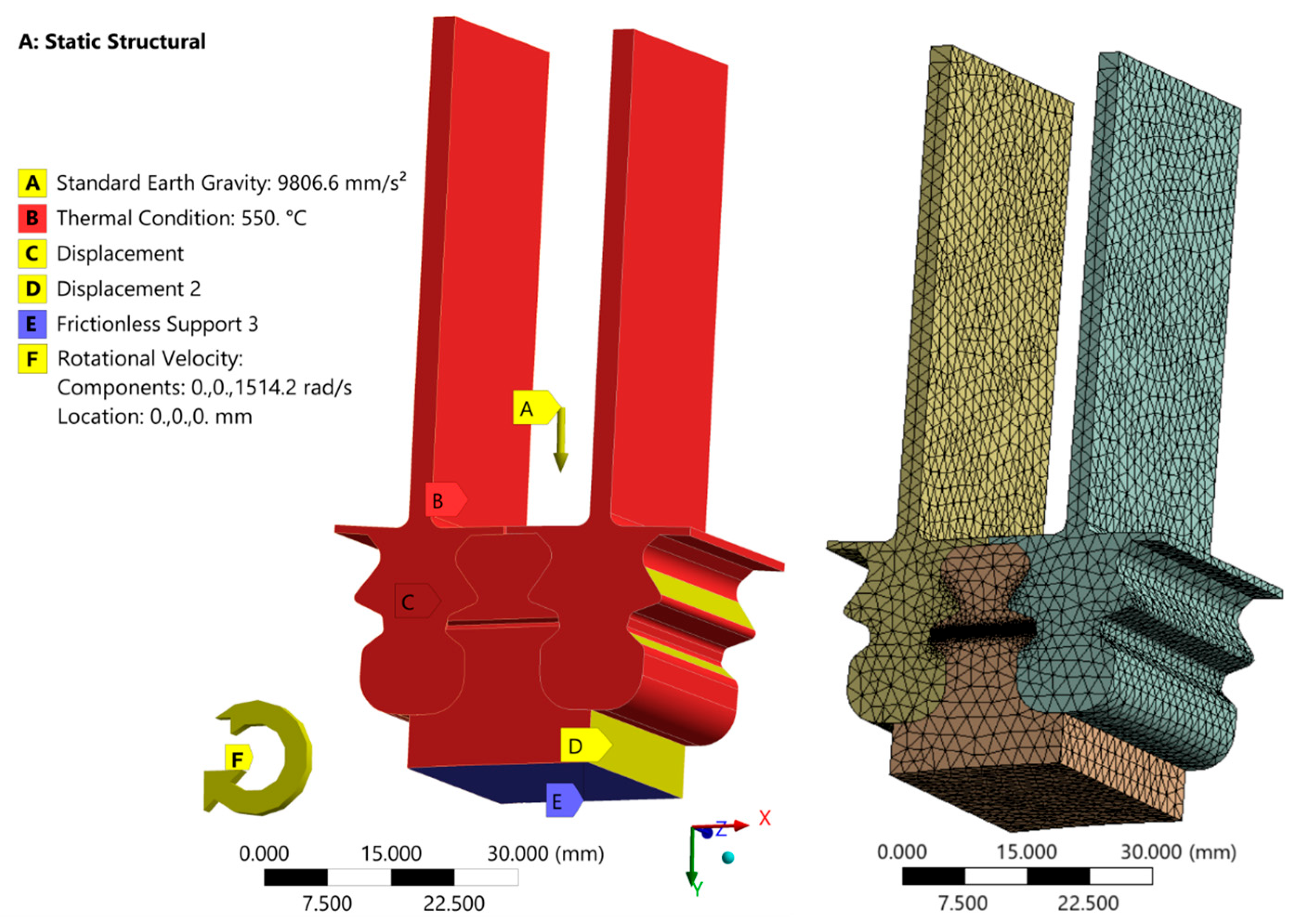
The cause of the observed fretting damage was not disclosed to the authors of this paper, but it can be assumed that the poor mounting of components of the HPT led to undesired contact during operation. The source of the damage was fixed and eliminated in the workshop, but the MRO company issued a request for the determination of its potential impact on the mechanical and structural integrity of the unit (rotor tooth/tenon). According to data obtained from the MRO, the designed service life of the HPT rotor disk was 20,000 cycles, where 1 cycle corresponds to 1 take-off (T/O). The MRO company also provided load data. Loads are generated mainly due to centripetal forces acting on the blade–disk attachment at an applied rotational velocity, with additional thermal loading during the operation. The maximum loading of the rotor disk occurs during the take-off (T/O), when the rotational velocity is 14,460 rpm (1514.2 rad/s), at a constant temperature of 550 °C. In addition to this official request, it was decided to conduct the study on the most probable location of the eventual crack initiation on the HPT slot elements since the observed fretting damage appeared in an unexpected site. Toward this aim, finite element analysis was performed, with the assumed crack at the location of fretting damage or without it, using a new option in the ANSYS simulation of crack initiation [27].

3. Finite Element Model of HPT Rotor Disk Blade–Slot Assembly

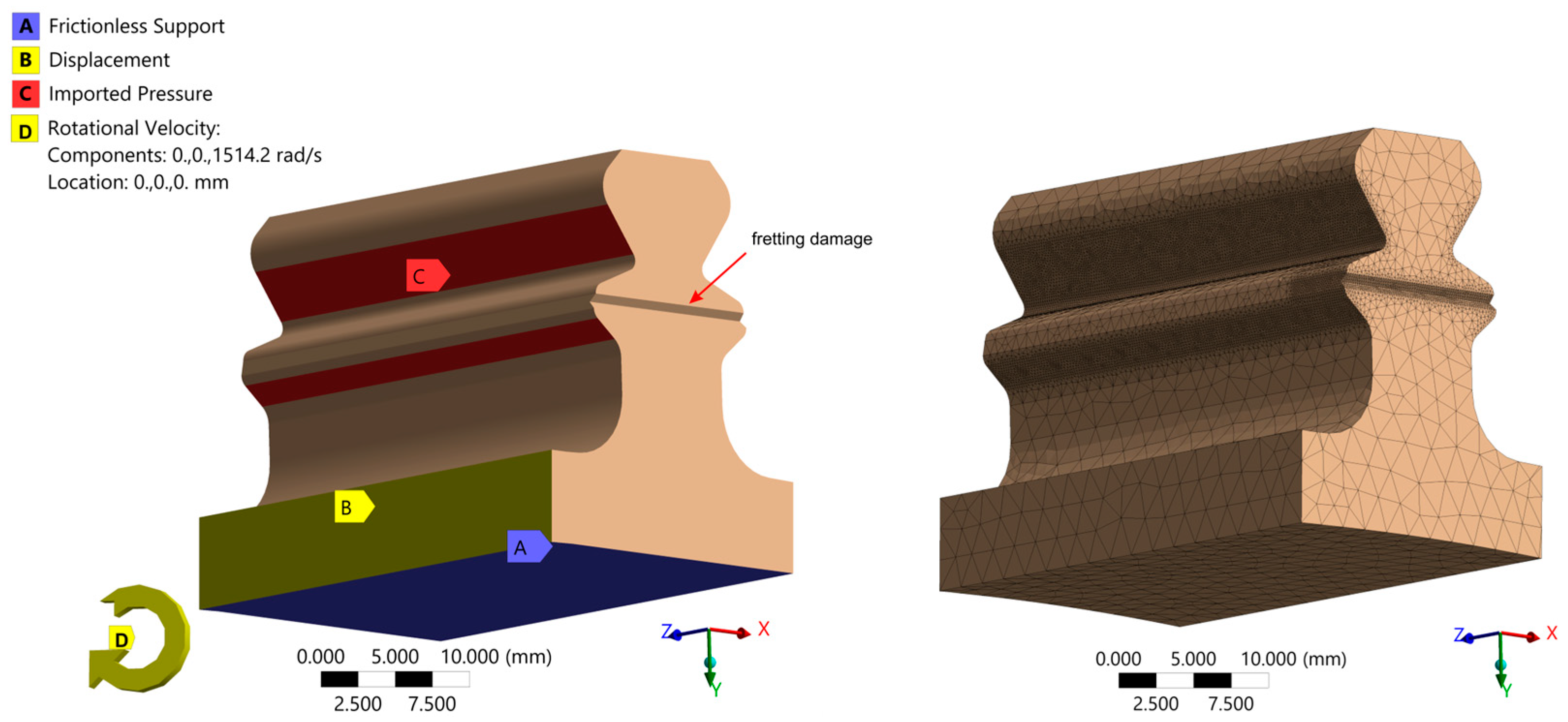
The FE analysis (FEA) began by evaluating contact loading on the disk tooth. For that purpose, the FEA of the HPT rotor disk blade–slot assembly was carried out. The assembly is represented by a two-blade sector configuration, based on the Laser Scan and Electronic Support Measures (ESM) data, and the finite element model was defined accordingly (Figure 2). The patch-conforming mesh method, which utilizes tetrahedral elements, was used to discretize geometry. The mesh was created with a higher 3D 10-node solid element SOLID 187, with three degrees of freedom per node: translations in the nodal X, Y, and Z directions. This element exhibits quadratic displacement behavior and supports plasticity, hyper-elasticity, creep, stress stiffening, large deflection, and large strain capabilities [13]. After conducting a mesh independence study, the mesh with 206,856 elements (302,412 nodes) was selected for FEA.
The mechanical and thermal properties of Inconel 718 used in numerical analyses are given in Table 1.
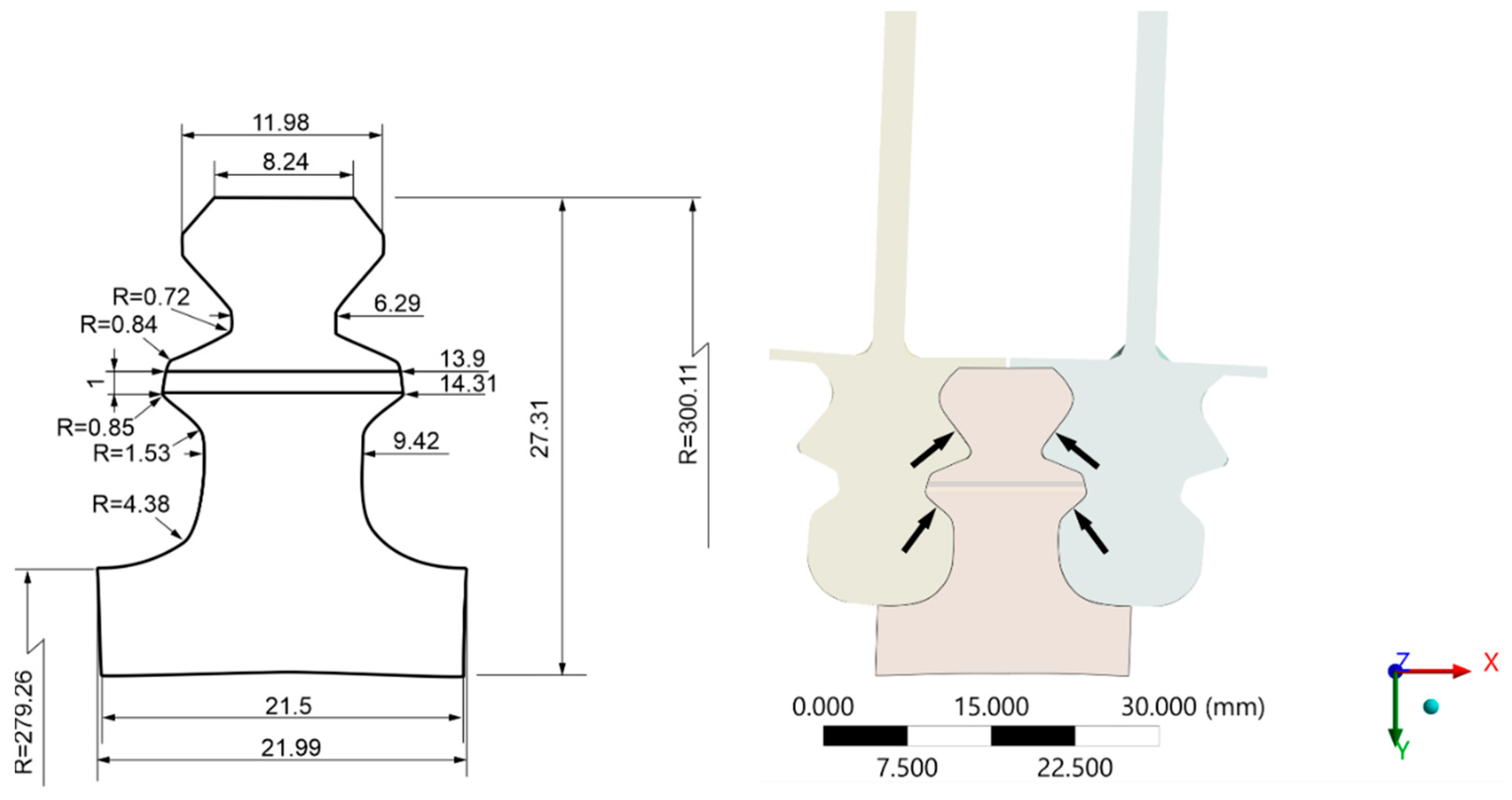
As already mentioned, loads are generated mainly due to centripetal forces acting on the blade–disk attachment, with additional thermal loading during the operation. Special attention was paid to model surfaces in contact during operation (Figure 3). These contact surfaces represent possible fretting crack initiation locations [1,3,6,7,8,12]. Contact modeling is based on the Coulomb friction model [27], introducing the limit frictional stress ( τ l i m ). If there is no motion between two contacting surfaces, the equivalent shear stress is less than a limit frictional stress. This state is known as sticking. The model defines an equivalent shear stress at which sliding on the surface begins as a fraction of the contact pressure.
Once the shear stress exceeds the limit value, the two surfaces will slide relative to each other. The limit frictional stress is defined as
τ = P μ + b ,   τ τ l i m
where τ l i m is the limit frictional stress, μ is the coefficient of friction (COF), P is contact normal pressure, and b is contact cohesion, which is a real constant used for the friction (default b   =   0 ), with units of stress. It provides sliding resistance, even with zero normal pressure. The equivalent shear stress is defined as
τ = τ   e q u i v a l e n t   s t r e s s   f o r   2 D   c o n t a c t τ 1 2 + τ 2 2   e q u i v a l e n t   s t r e s s   f o r   3 D   c o n t a c t
where that τ 1 and τ 2 are considered in the tangential contact plane between the surfaces in contact.
The sticking/sliding calculations determine the transition point from sticking to sliding or vice versa. Since real bodies in contact do not penetrate each other, the program must establish a relationship between the two surfaces to prevent them from passing through each other in the analysis. This is done using the Augmented Lagrange contact formulation, which enforces contact penalty-based compatibility at the contact interface. It is an iterative process to find the Lagrange multipliers (i.e., contact traction). The contact pressure is defined by
P = 0   i f   u n > 0 K n u n + λ i + 1   i f   u n 0
where K n is contact normal stiffness and u n is the contact gap size. Here, the Lagrange multiplier λ is an internally calculated term that augments the penalty-based force calculation. The purpose of the augmentation is to reduce sensitivity to contact stiffness. It is computed locally (for each element) and iteratively:
λ i + 1 = λ i + K n u n   i f   u n > ε λ i   i f   u n < ε
where ε is compatibility tolerance, i.e., a penetration tolerance factor with a default value of 0.1, while λ i is the Lagrange multiplier component at iteration i.
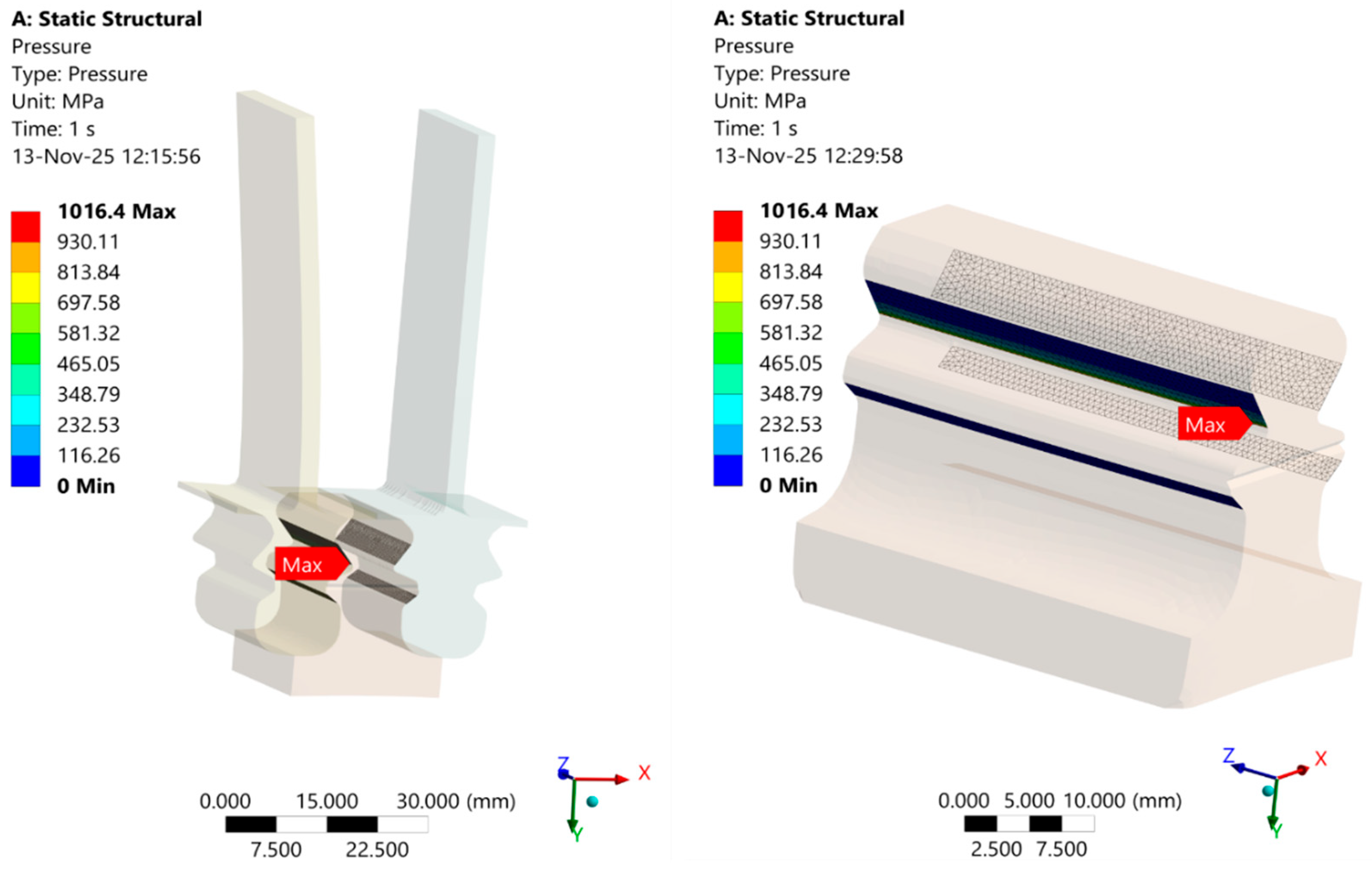
Apart from defining contact surfaces and selecting a contact formulation, the program required the input of COF, which in this case was set to 0.5935, extrapolated for the temperature of 550 °C, based on the data that can be found in [9]. The FEA revealed contact pressures on possible fretting fatigue locations. The maximum contact pressure was 1016.4 MPa at the position that, as can be seen in Figure 4, corresponds to the positions of fretting fatigue cracks observed in practice and presented in the literature [1,3,6,7,8,12].
Then, a series of crack propagation analyses was carried out based on linear elastic fracture mechanics (LEFM) assumptions. These analyses focused on the rotor tooth, shown in Figure 5, and they contained a complete analysis sequence: preprocessing (3D modeling, specification of material properties including Paris’ coefficients for Inconel 718 [36], generation of finite element mesh, application of loads and boundary conditions, the definition of parameters for crack propagation), solving, and postprocessing.
Initial fretting damage was modeled in the form of a wedge that was 0.5 mm deep and 1 mm wide, as shown in Figure 5. The boundary and loading conditions (gravity, centripetal forces due to rotational velocity, and thermal loading) applied on the HPT rotor disk blade–slot assembly were applied on the rotor tooth too, with additionally applied contact pressure as an imported load. The mesh generation settings were the same as in the previous analysis. SMART was used for crack propagation simulation, which supports mixed-mode crack propagation for modes I and II. It has to be noted that since the observed fretting damage occurred in the unexpected location, and that, according to the MRO, the cause of fretting damage was eliminated, the analyzed crack initiation and propagation were treated as plain fatigue rather than fretting fatigue phenomena.

4. Crack Models Used in FEA and Obtained Results

One of the crucial questions was how to model observed damage caused by unexpected fretting. In ANSYS, different approaches to crack modeling are available, as well as several crack shapes: pre-meshed crack, arbitrary crack (AC), semi-elliptical crack, elliptical crack (EC), corner crack (CC), edge crack, through-crack, ring crack, and cylindrical crack. The crack initiation feature (CIF), where the software automatically inserts the crack in the FE model, is also available as the newest option in ANSYS [27]. Here, the pre-meshed crack and the crack initiation feature are used to model the crack, based on the existing fretting path. The SMART settings were the same for all analyzed crack shapes except for the crack increment size in the case of a pre-meshed crack. In all cases, the Paris crack propagation law was used.

4.1. The Pre-Meshed Crack

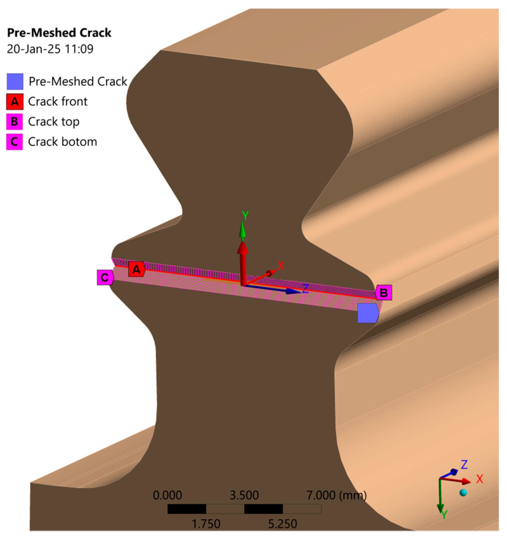
The pre-meshed crack (PMC) implies that the crack is physically included in the geometry model and is meshed along with the geometry. From that mesh, a corresponding group of nodes is selected to represent the crack front (these nodes have to be in a single plane) and top and bottom faces. Here, the crack front was created from the wedge edge nodes, and the top and bottom faces from the upper and lower wedge surfaces, as shown in Figure 6. This crack is defined within its local coordinate system, which determines the position and orientation of the crack, with the y-axis representing the crack surface’s normal, and the x-axis defining the direction of crack propagation. One should notice that the term crack extension will also be used in the following text to define the extent of crack propagation.
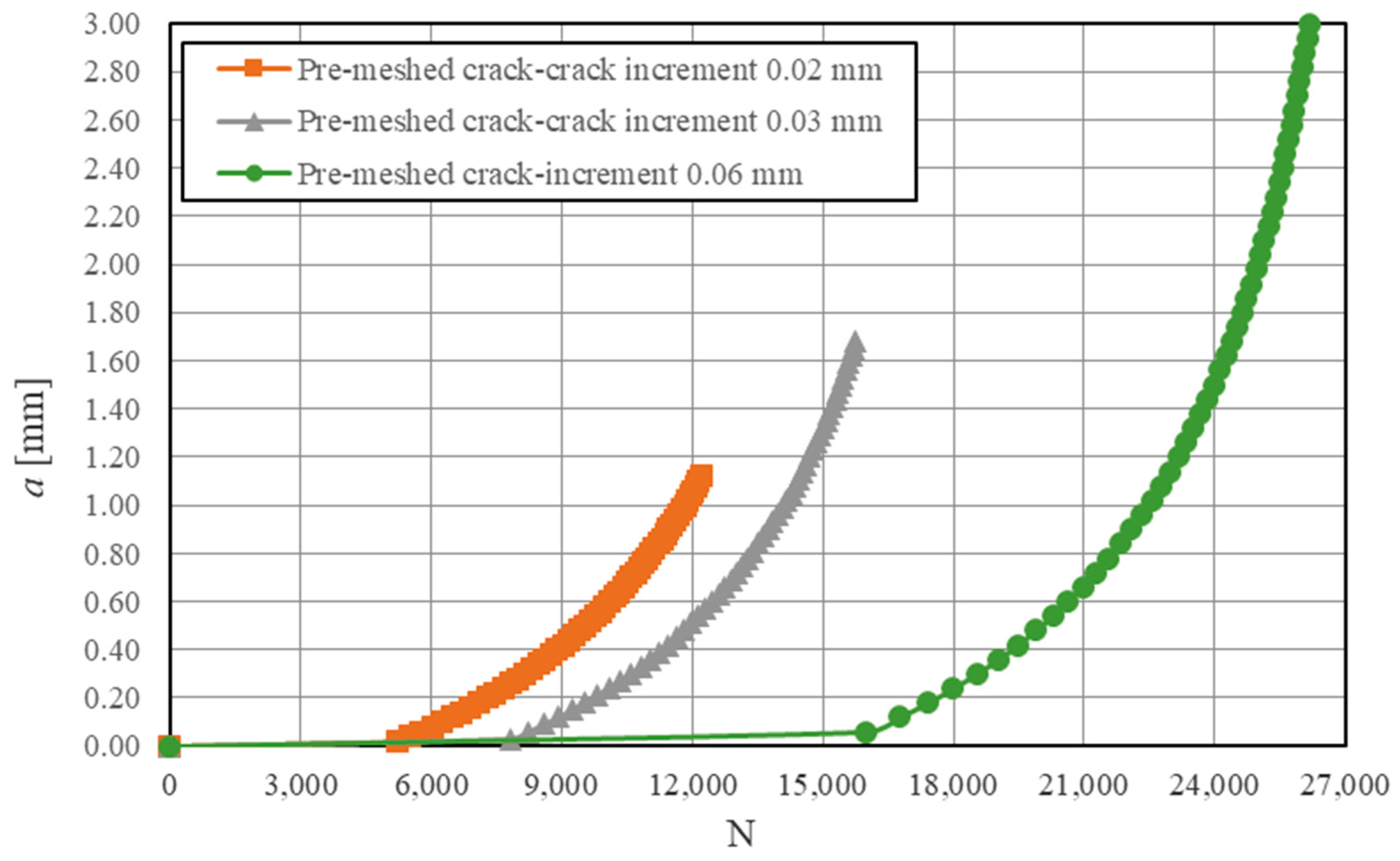
When the simulation is conducted with multiple sub-steps, as required for the crack propagation simulations, it is important to specify the crack extension increments for every sub-step. In the simulations carried out, three different crack increment sizes were used: 0.02 mm, 0.03 mm, and 0.06 mm. The size of the crack increment is related to the finite element size in the zone of the pre-meshed crack, which in this case was 0.25 mm. In the ANSYS software, the recommended crack increment is at least 20% of the finite element size; otherwise, the accuracy of the solution can be affected, and unstable crack propagation might appear. This was confirmed here, since it was discovered that the number of cycles (remaining fatigue life) was very sensitive to this parameter, as can be seen in Figure 7. The combination of the average element size of 0.25 mm and crack increment of 0.06 mm provided the most stable crack propagation, with the crack reaching the maximum depth.
One should notice that denser meshes, with smaller element sizes (and hence smaller crack increments), did not allow crack propagation at all, or—at best—the crack propagated in only a few sub-steps and then calculations stopped since the appropriate mesh could not be generated.
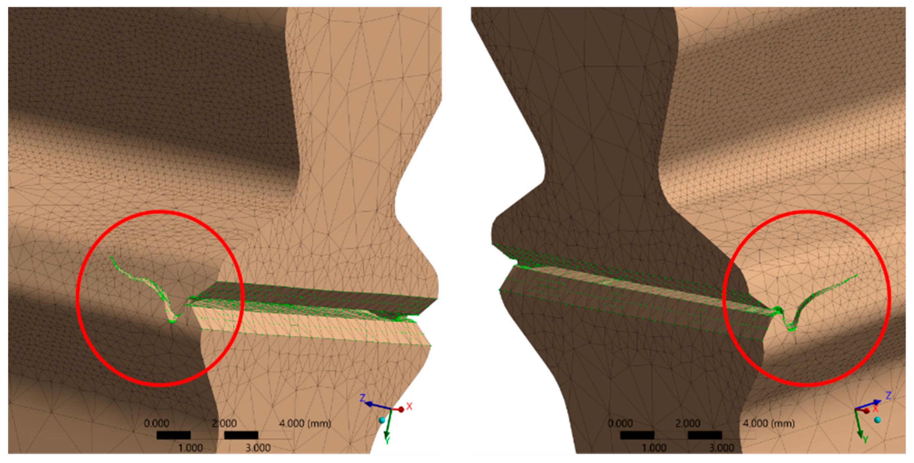
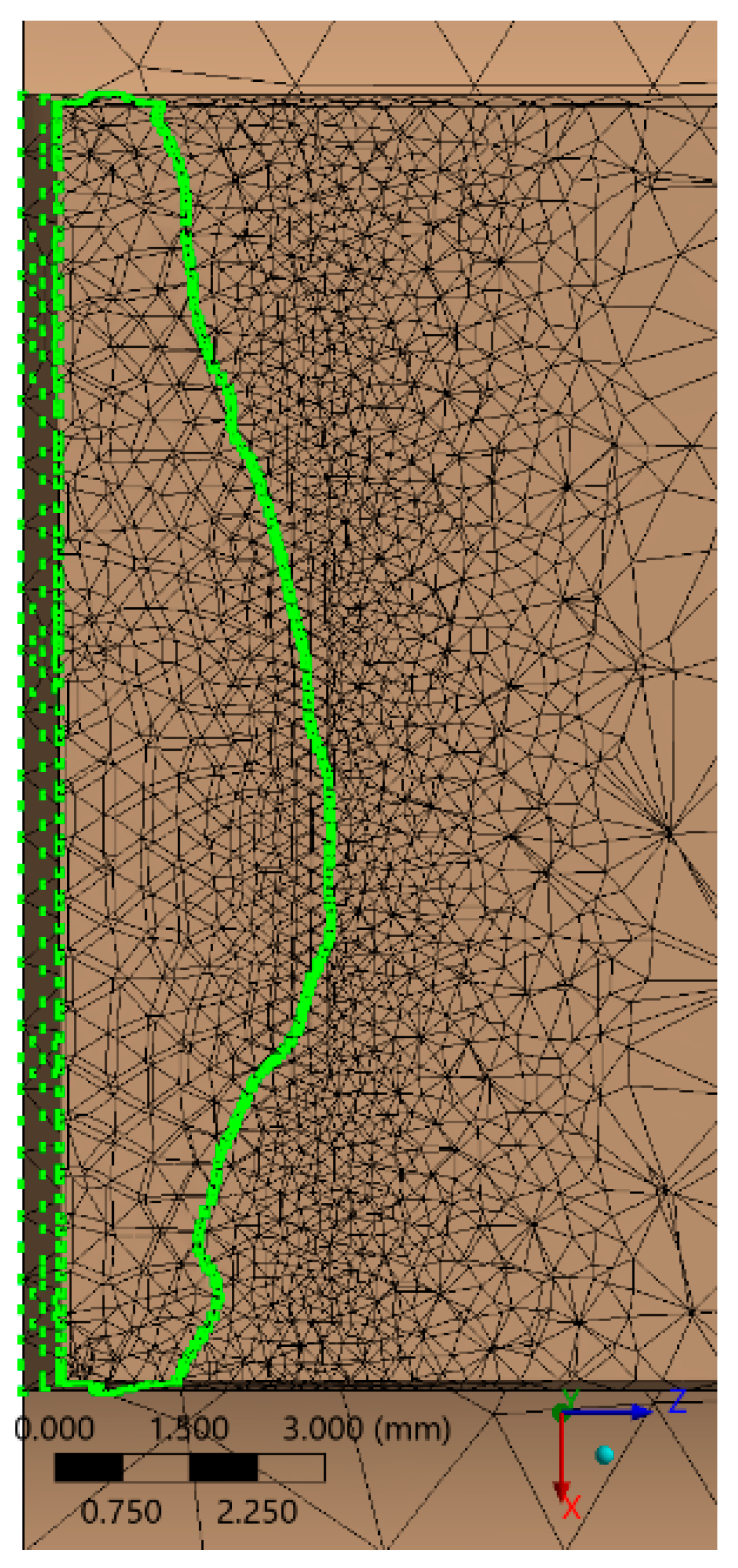
The crack path obtained with an increment size of 0.06 mm is shown in Figure 8, while the maximum depth achieved is shown in Figure 9.
After initial twisting, the crack propagated nearly in a plane through the whole width of the tooth, with a left inclination a bit upwards, corresponding to the direction of the applied rotational velocity. The crack reached a maximum of 3 mm in 50 steps after 26,169 cycles.
The maximum SIF on the crack front was 667.43   M P a m m . Structural integrity of the part analyzed was not affected since it was designed to last 20,000 cycles. After 20,000 cycles, the crack extension is only about 0.5 mm, and the graph in Figure 7 shows that the analyzed crack is still far from unstable propagation.

4.2. Crack Initiation

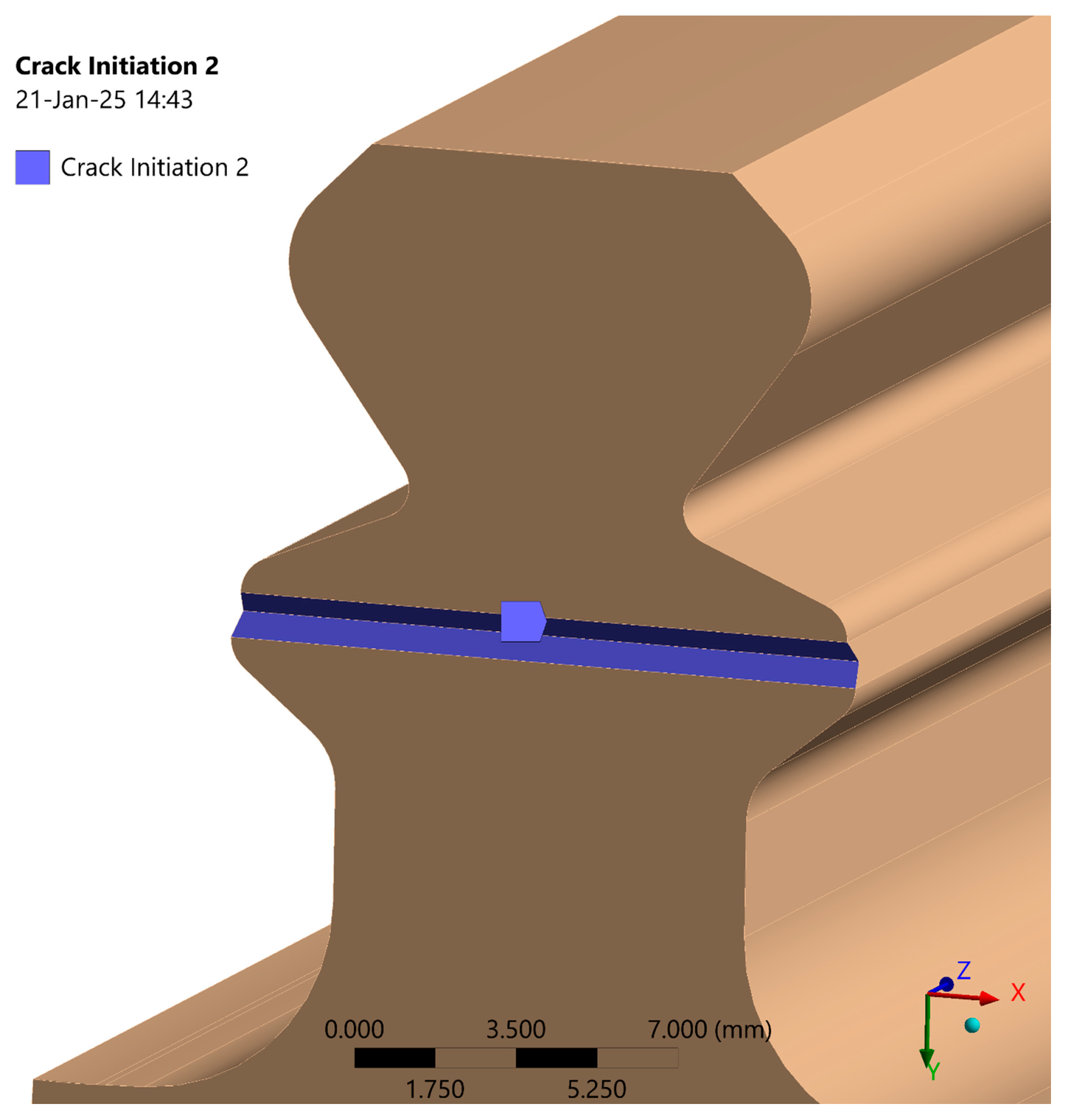
Crack initiation usually occurs at the surface of a component during cyclic fatigue loading in the presence of a stress concentration, like a surface defect [37]. This makes the crack initiation feature (CIF) a logical choice for fatigue crack simulation in the presence of fretting damage. This feature automatically inserts an elliptical crack in a location where a certain criterion is satisfied. The dimensions of the elliptical crack are automatically determined by averaging the element sizes in the vicinity of the chosen location, which also determines the crack orientation, shown in Figure 10.
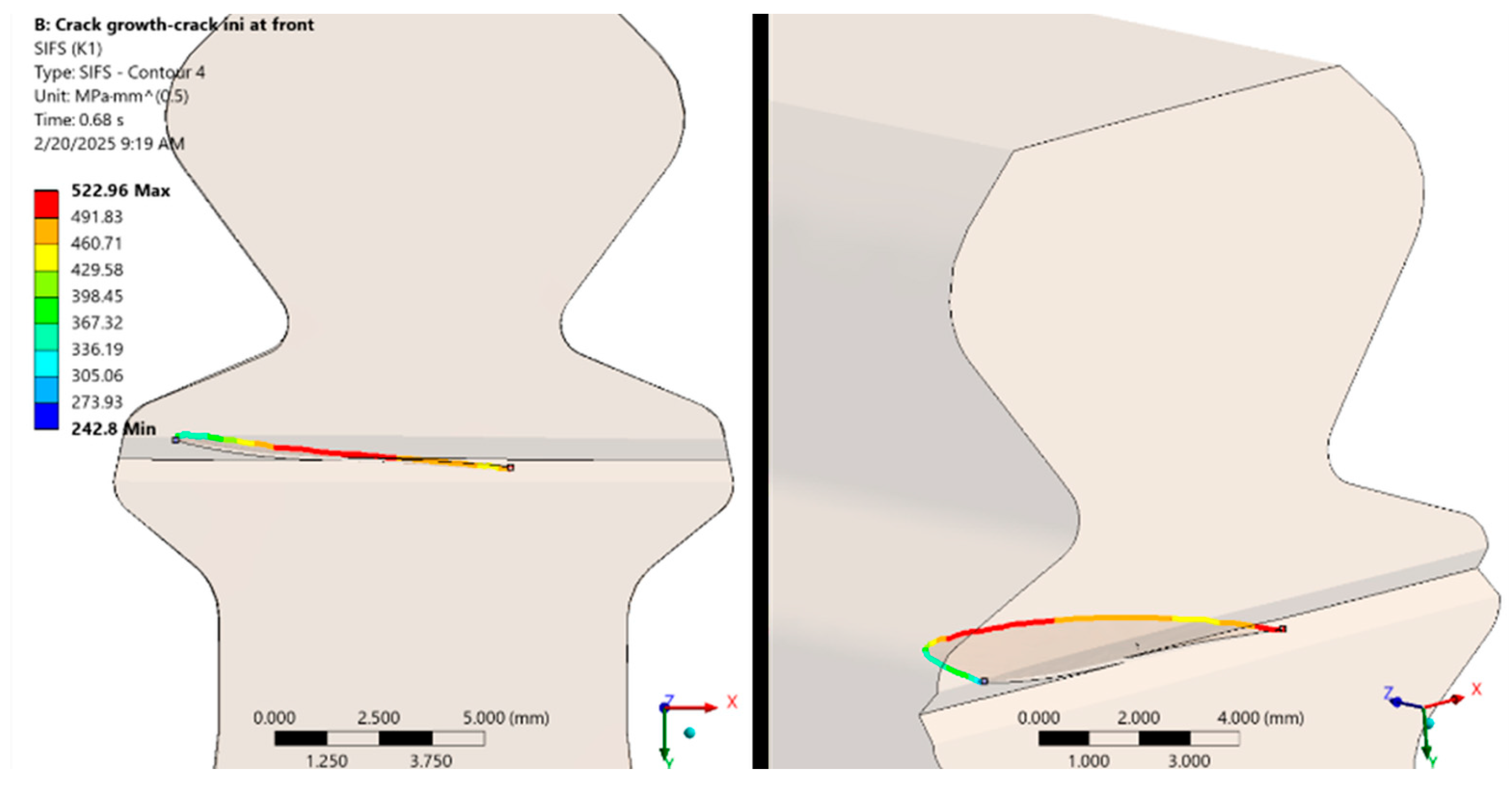
The criterion in ANSYS for crack initiation is the maximum principal stress (MPS), a user-defined parameter. Cracking will not be initiated until the predefined critical MPS value is reached. This is usually the value of the yield strength, which is 1034 MPa for Inconel 718 [38]. However, after applying the load, the MPS of 1034 MPa was not reached in the selected region, meaning that there would be no crack initiation and propagation. For the crack to be initiated in the observed region, the critical MPS value had to be lowered to 845 MPa. This value was chosen based on the stress values calculated for that region. In that case, the crack extended to 3.63 mm in 101 sub-steps. The number of cycles obtained at this extension was N = 10,104 . The maximum SIF for the achieved crack size was 522.96   M P a m m , shown in Figure 11. The propagation was nearly in a plane, with a similar inclination as in the previous two cases.
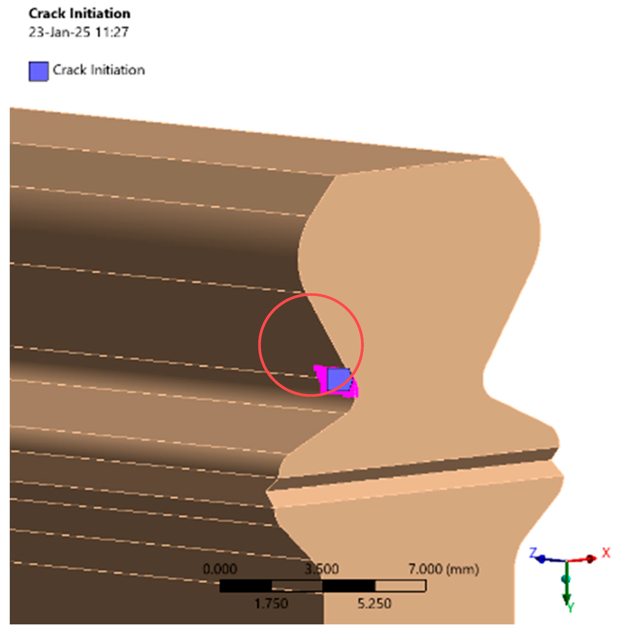
A high value of the imported contact loads at the position of fatigue crack initiation found in the literature raised the question of crack initiation in these areas. It seems that the crack is highly likely to occur in the area shown in Figure 11 and not in the area where the fretting damage was observed in the workshop. So, further analysis was carried out, where the crack initiation was assumed in the region with the largest contact loads, as shown in Figure 12. According to [39], such cracks typically propagate normally to the contact surface.
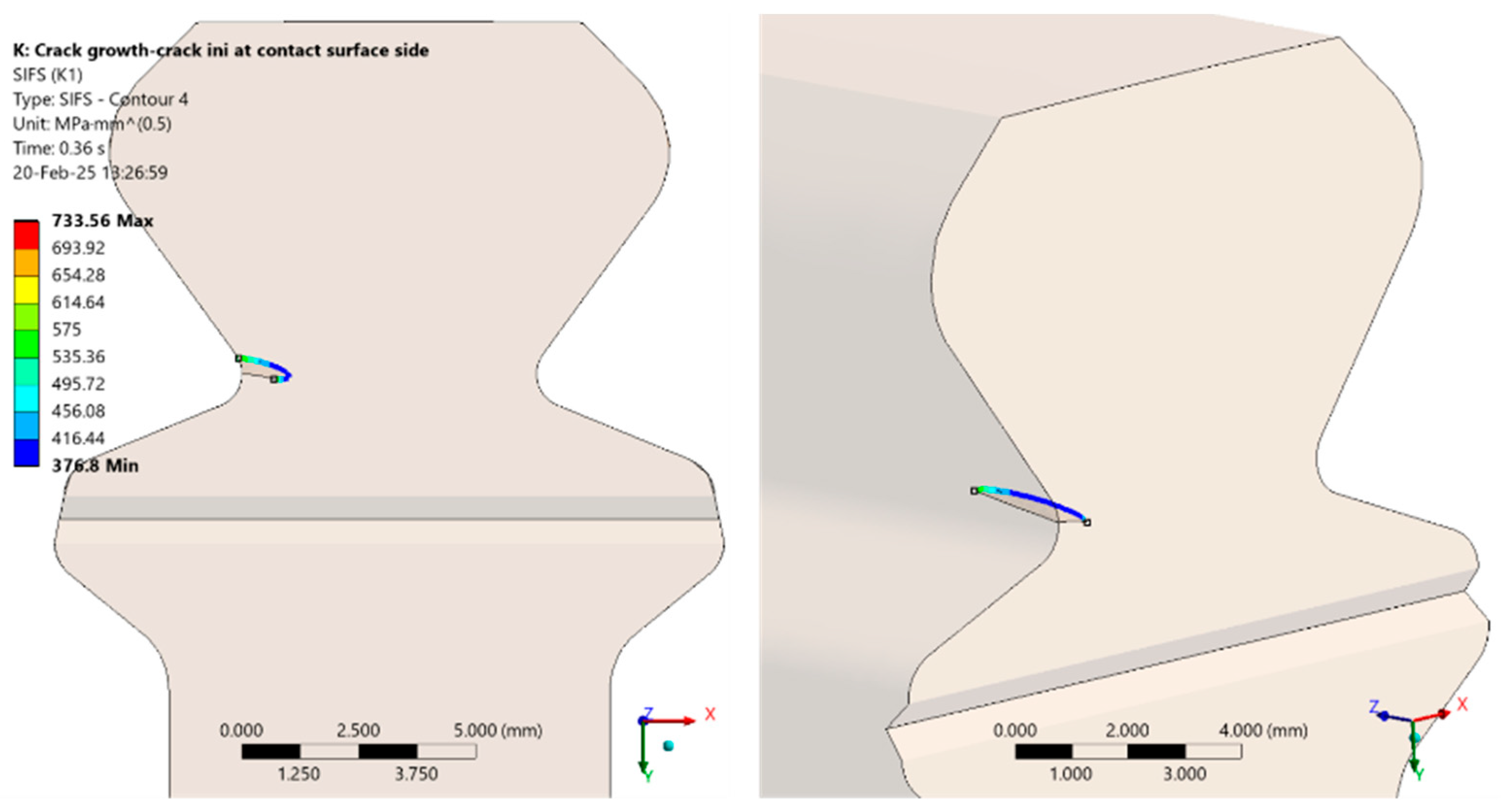
The FEA indicated that MPS = 1056 MPa in the region shown in Figure 12, which was higher than the critical value 1034 MPa. So, the crack is very likely to appear here under the applied load, even when the virgin material properties are used. In this case, the crack initiated in the observed region and extended to 0.93 mm in 75 sub-steps. The corresponding number of cycles was 899. The maximum SIF for the achieved crack extension was 733.56   M P a m m , shown in Figure 13. It is important to emphasize that this crack was propagating in the tooth geometry with the inserted fretting path (in the form of a wedge), indicating that it is more likely for the crack to appear in the contact area rather than in the existing fretting path.
The next analysis was carried out with the same crack initiation region, but without the fretting damage, to investigate its influence on crack initiation and propagation.
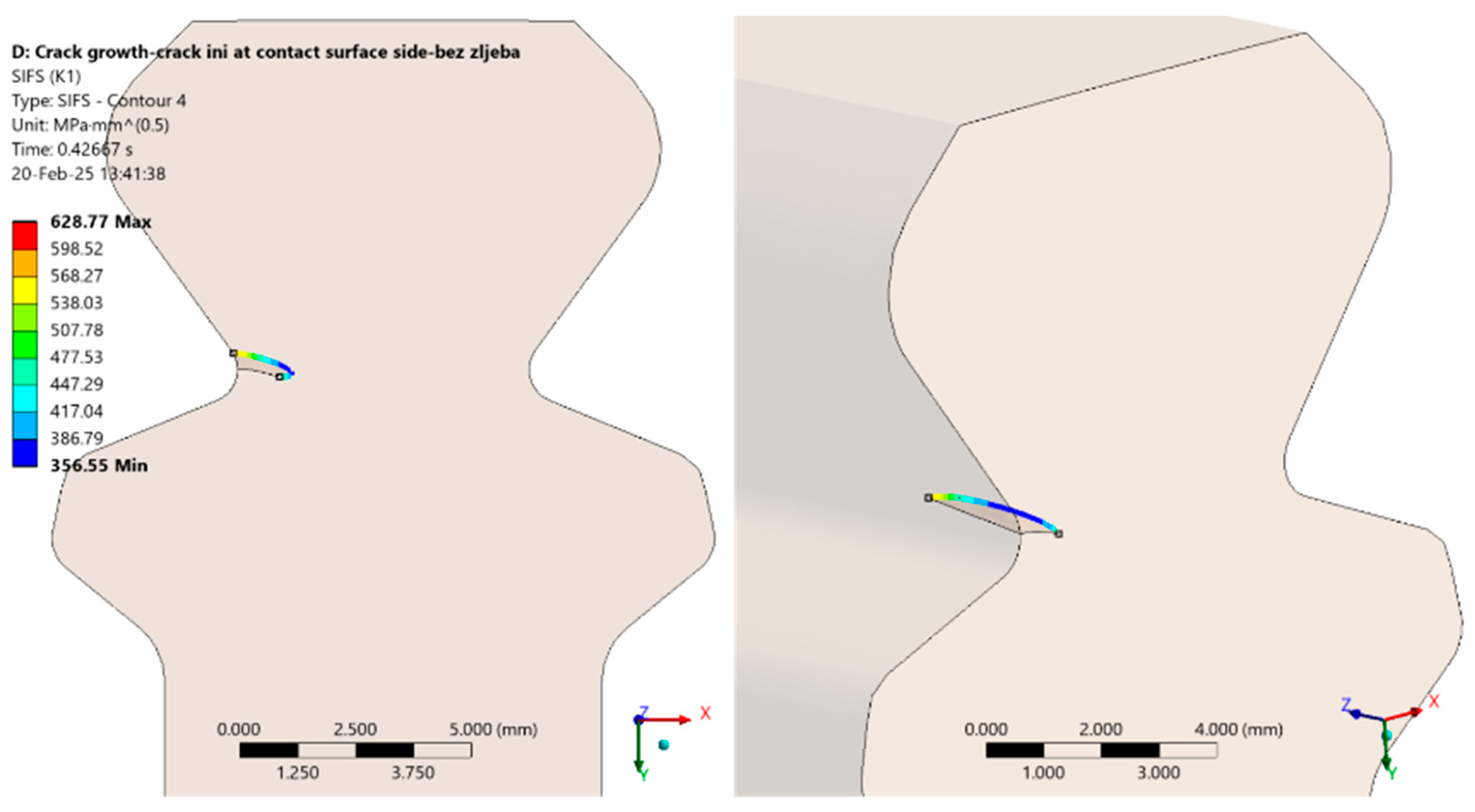
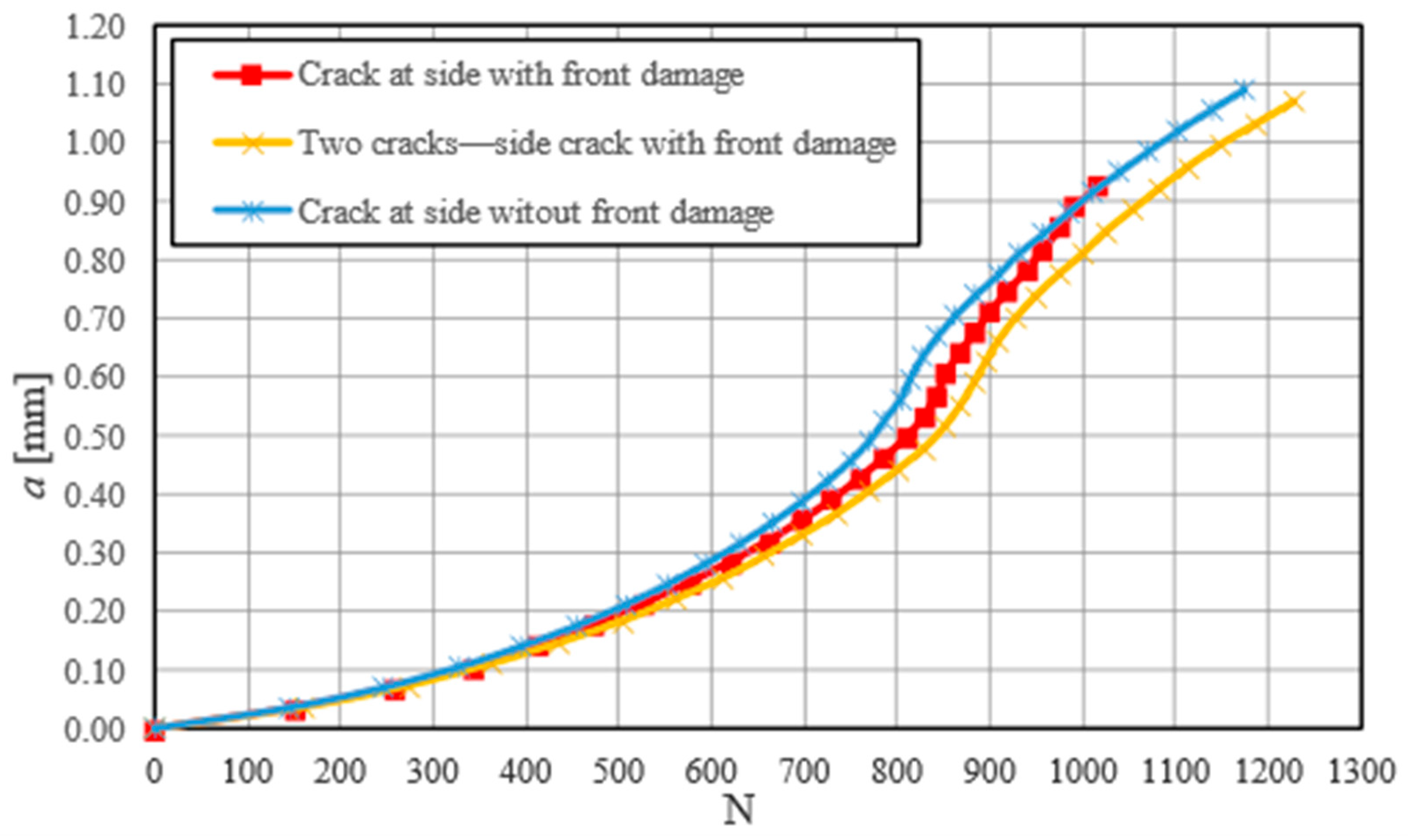
This analysis showed that the MPS in the crack initiation region (1071 MPa) was almost the same as the value obtained before. The newly formed crack extended to 1.092 mm in 32 sub-steps. The number of cycles at this crack extension was N = 1174 . The maximum SIF for the achieved crack size was 628.77   M P a m m , as shown in Figure 14. Obviously, the fretting path has no influence on the crack propagation from the region with the highest MPS.
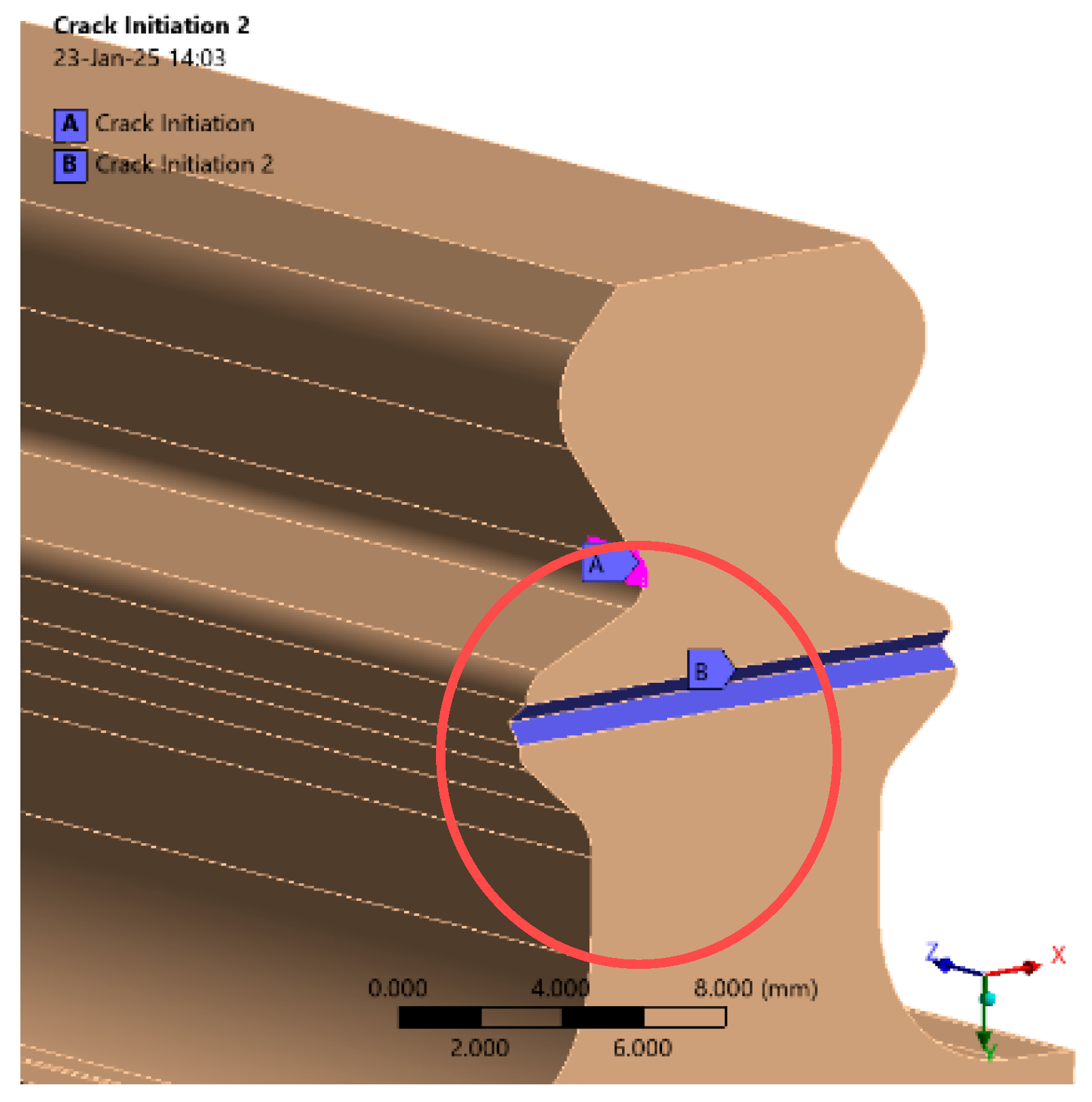
The final analysis conducted included two crack initiation regions: the region where the fretting path (in the form of a wedge) exists and the contact region with the highest contact pressure. This is shown in Figure 15.
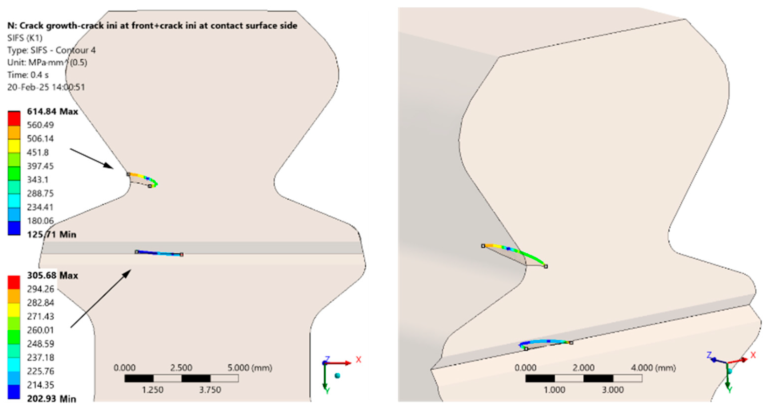
In this case, the crack from the contact region extended to 1.068 mm while the front crack extended to 0.706 mm in 30 sub-steps, with the number of loading cycles being 1228. The maximum SIF for the first crack was 614.84   M P a m m , while for the second, the maximum value was 305.68   M P a m m , as shown in Figure 16.

5. Discussion

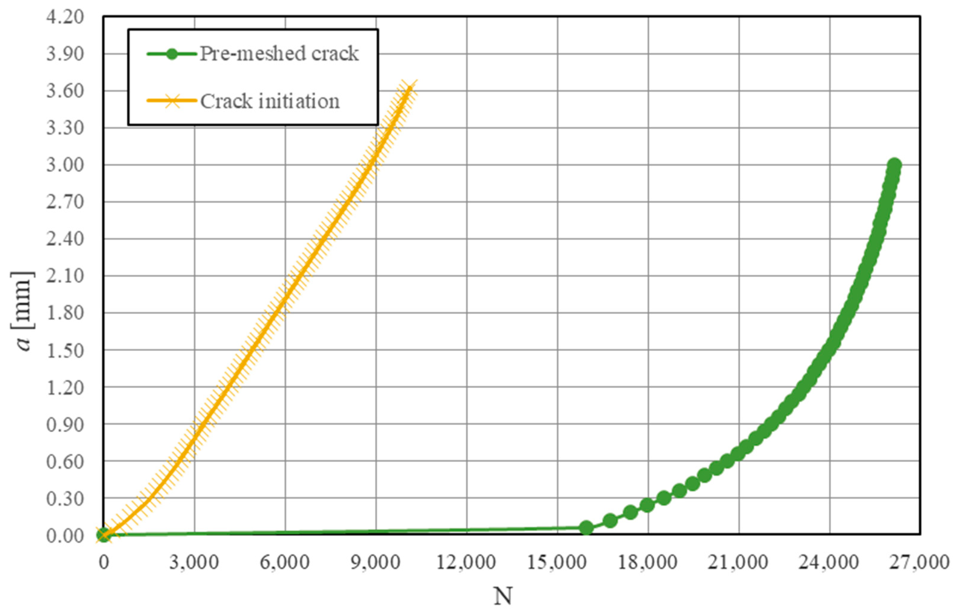
It is well known that overall fatigue life represents the sum of crack initiation and crack propagation life. Since there is no universal criterion that delineates these two phases, it is common engineering practice that the crack initiation life represents the number of cycles needed for a microscopically observable crack to be developed [13]. Here, the fretting damage was considered as that observable crack, so the crack propagation lives were estimated and compared. All previously presented results are summarized in the graphs shown in Figure 17 and Figure 18.
Figure 17 shows large differences between the calculated cycles for two analyzed crack models. For the pre-meshed crack model, the fretting damage was completely modeled as a long and narrow wedge (compared to the size of the rotor tooth), while in the case of crack initiation, the damage was inserted as a small elliptical crack (CIF option). This affected the mesh density in the crack zone, making the mesh significantly different for the mentioned crack models, though all mesh settings were the same. In contrast, the estimated number of cycles when cracks are automatically initiated in the zone with the MPS is not significantly different, as shown in Figure 18.
On the other hand, the pre-meshed crack model can be very accurate for crack propagation predictions since it approximates the fretting damage precisely. However, the particular geometry of the fretting damage makes crack modeling difficult since it goes through the entire width of the rotor tooth with very low depth. This greatly complicates the mesh generation for every newly defined crack front, and the choice of the crack increment value strongly influences the result. Nonetheless, Figure 17 and Figure 18 show that the calculated number of cycles for the pre-meshed crack is much higher than that calculated for cracks initiated in the region with the MPS. In the latter case, the crack extension of 0.3 mm is reached after 660 or fewer loading cycles, while for the pre-meshed crack, the same crack extension is reached after 1500 cycles or more.
Finally, from a practical point of view with respect to the aim of this research, one should notice that the pre-meshed crack modeling predicts significantly longer remaining life than the CIF modeling. Anyhow, as one can see from Figure 17, the number of cycles is satisfying in any case, since more than 10,000 are needed for a crack extension of 3.6 mm. Another important point is that the fretting damage is actually not the critical area, since the MPS is higher in the contact pressure area due to loading and geometry. In other words, the remaining life of the whole component is not affected by the fretting damage.

6. Conclusions

In this paper, a numerical approach was used to investigate the remaining life of a damaged aircraft engine component made of Inconel 718, based on the data provided from the MRO workshop. Keeping in mind that this component is not repairable, and its replacement might be time-consuming and/or too expensive, it was essential to evaluate how to prevent failure if this component were to be used with the damage that was observed in an unexpected position.
Based on the presented results, the following conclusions can be drawn:
  • The remaining life of the damaged aircraft engine component is not affected by the fretting damage since the highest value of MPS is not in the damage area.
  • Crack modeling using pre-meshed and CIF options predicts significantly different remaining lives, indicating the need for further and more detailed numerical simulation, using other options provided by ANSYS.
  • Experimental verification of numerical results is also needed to find out which crack modeling option is the most realistic.

Author Contributions

Conceptualization, A.G.; methodology, A.G.; software, A.G.; validation, N.V.; formal analysis, G.K. and N.V.; investigation, H.A.; resources, N.V.; data curation, M.B. and H.A.; writing—original draft preparation, G.K.; writing—review and editing, M.B.; supervision, A.G. All authors have read and agreed to the published version of the manuscript.

Funding

This research did not receive any specific grant from funding agencies in the public, commercial, or not-for-profit sectors.

Data Availability Statement

The original contributions presented in the study are included in the article; further inquiries can be directed to the corresponding author.

Conflicts of Interest

The authors declare no conflicts of interest.

References

  1. Suresh, S. Fatigue of Materials, 2nd ed.; Cambridge University Press: Cambridge, UK, 1998; p. 469. [Google Scholar]
  2. Mokhles, M.; Liu, G.; Shishavan, B.H.; Dandekar, T.R.; Barouni, A.; Birosca, S. New insights on the deformation mechanism of fretting fatigue in Ti-6Al-4V. Acta Mater. 2025, 291, 120998. [Google Scholar] [CrossRef]
  3. Hattori, T. Fretting Wear, Fretting Fatigue and Damping of Structures Design Engineering Handbook Learned from Failure Cases, Solid Mechanics and Its Applications; Springer Nature Switzerland AG: Cham, Switzerland, 2024; Volume 276. [Google Scholar] [CrossRef]
  4. Szolwinski, M.P.; Farris, T.N. Mechanics of fretting fatigue crack formation. Wear 1996, 198, 93–107. [Google Scholar] [CrossRef]
  5. Nicholas, T. Critical issues in high cycle fatigue. Int. J. Fatigue 1999, 21, S221–S231. [Google Scholar] [CrossRef]
  6. Bharatish, A.; Srihari, P.V.; Panchal, A.; Narasimhamurthy, H.N. Analysis of Fir Tree Root of Aero-engine Disk Assembly for Simultaneous Optimization of Fretting Characteristics. J. Inst. Eng. India Ser. 2019, 100, 859–868. [Google Scholar] [CrossRef]
  7. Enright, M.P.; Chan, K.S.; Moody, J.P.; Golden, P.J.; Chandra, R.; Pentz, A.C. Probabilistic Fretting Fatigue Assessment of Aircraft Engine Disks. ASME. J. Eng. Gas Turbines Power 2010, 132, 072502. [Google Scholar] [CrossRef]
  8. Mangardich, D.; Abrari, F.; Fawaz, Z. A fracture mechanics based approach for the fretting fatigue of aircraft engine fan dovetail attachments. Int. J. Fatigue 2019, 129, 105213. [Google Scholar] [CrossRef]
  9. Xu, Z.; Lu, Z.; Zhang, J.; Li, D.; Liu, J.; Lin, C. The Friction and Wear Behaviours of Inconel 718 Superalloys at Elevated Temperature. Front. Mater. 2021, 8, 794701. [Google Scholar] [CrossRef]
  10. Sun, D.; Huo, J.; Chen, H.; Dong, Z.; Ren, R. Experimental study of fretting fatigue in dovetail assembly considering temperature effect based on damage mechanics method. Eng. Fail. Anal. 2021, 131, 105812. [Google Scholar] [CrossRef]
  11. Zhou, J.; Yang, B.; Li, S.; Huo, J. Fretting Fatigue Life Prediction of Dovetail Structure Based on Plastic Effect and Sensitivity Analysis of Influencing Factors. Materials 2023, 16, 3521. [Google Scholar] [CrossRef] [PubMed]
  12. Lindley, T.C.; Nix, K.J. Case studies in power engineering plant. In Fatigue Crack Initiation and Damage Counters; Societe de Metallurgie: Paris, France, 1991. [Google Scholar]
  13. Wang, Z.G.; Wang, Z.; Sun, K.; Chen, S.; Zheng, Y.; Fang, X.; Cai, Z. Fretting fatigue damage and crack propagation of shot-peening dovetail joints assisted with the U-Net model. Int. J. Fatigue 2025, 199, 109074. [Google Scholar] [CrossRef]
  14. Guo, K.; Yuan, H. Nonlocal fretting fatigue assessment for dovetail joints. Int. J. Fatigue 2024, 185, 108337. [Google Scholar] [CrossRef]
  15. Shen, Z.; Huang, Z.; Wang, J.; Zheng, L.; Qian, H.; Zhu, Q. Investigation of fretting fatigue performance for IN718 dovetail joint in very high cycle regime. Int. J. Fatigue 2025, 195, 108874. [Google Scholar] [CrossRef]
  16. Balać, M.; Grbović, A.; Petrović, A. Numerical predictions of crack propagation in a pressure vessel with welded nozzles. Struct. Integr. Life 2015, 15, 55–61. [Google Scholar]
  17. Rege, K.; Lemu, H.G. A review of fatigue crack propagation modelling techniques using FEM and XFEM. Mater. Sci. Eng. 2017, 276, 012027. [Google Scholar] [CrossRef]
  18. Sedmak, A.; Sedmak, S.; Čolić, K. Structural integrity and life of hip implants: Review of case studies. Struct. Integr. Life 2025, 25, 509–520. [Google Scholar] [CrossRef]
  19. Sedmak, A. Computational fracture mechanics—An overview from early efforts to recent achievements. Fatigue Fract. Eng. Mater. Struct. 2018, 41, 2438–2474. [Google Scholar] [CrossRef]
  20. Sedmak, A. Fatigue crack propagation simulation by extended finite element method: A review of case studies. Fatigue Fract. Eng. Mater. Struct. 2024, 47, 1819–1855. [Google Scholar] [CrossRef]
  21. Petrašinović, D.; Rašuo, B.; Petrašinović, N. Extended finite element method (XFEM) applied to aircraft duralumin spar fatigue life estimation. Teh. Vjesn. 2012, 19, 557–562. [Google Scholar]
  22. Grbovic, A.; Sedmak, A.; Kastratovic, G.; Petrasinovic, D.; Vidanovic, N.; Sghayer, A. Effect of laser beam welded reinforcement on integral skin panel fatigue life. Eng. Fail. Anal. 2019, 101, 383–393. [Google Scholar] [CrossRef]
  23. Solob, A.; Grbovic, A.; Božić, Ž.; Sedmak, S. XFEM based analysis of fatigue crack propagation in damaged wing-fuselage attachment lug. Eng. Fail. Anal. 2020, 112, 104516. [Google Scholar] [CrossRef]
  24. Kumar, M.; Pandey, V.B.; Singh, I.V.; Mishra, B.K.; Ahmad, S.; Rao, A.V.; Kumar, V. A Numerical Study of Creep Crack Propagation in an Aero-engine Turbine Disk using XFEM. Procedia Struct. Integr. 2019, 14, 839–848. [Google Scholar] [CrossRef]
  25. Alshoaibi, A.M.; Fageehi, Y.A. Advances in Finite Element Modeling of Fatigue Crack Propagation. Appl. Sci. 2024, 14, 9297. [Google Scholar] [CrossRef]
  26. Greco, F.; Leonetti, L.; Lonetti, P.; Pascuzzo, A. Fatigue crack propagation simulation using the moving mesh technique. Fatigue Fract. Eng. Mater. Struct. 2023, 46, 4606–4627. [Google Scholar] [CrossRef]
  27. ANSYS. ANSYS Workbench, Release 25; ANSYS, Inc.: Canonsburg, PA, USA, 2024.
  28. Aleksić, B.; Grbović, A.; Milović, L.; Hemer, A.; Aleksić, V. Numerical simulation of fatigue crack propagation: A case study of defected steam pipeline. Eng. Fail. Anal. 2019, 106, 104165. [Google Scholar] [CrossRef]
  29. Arandjelovic, M.; Djordjevic, B.; Sedmak, S.; Radu, D.; Petrovic, A.; Dikic, S.; Sedmak, A. Failure analysis of welded joint with multiple defects by extended Finite Element Method and Engineering Critical Analysis. Eng. Fail. Anal. 2024, 160, 108176. [Google Scholar] [CrossRef]
  30. Đukić, D.; Grbović, A.; Kastratović, G.; Vidanović, N.; Sedmak, A. Stress intensity factors numerical calculations for two penny shaped cracks in the elastic solid. Eng. Fail. Anal. 2020, 112, 104507. [Google Scholar] [CrossRef]
  31. Alshoaibi, A.M. Numerical Modeling of Crack Propagation under Mixed-Mode Loading. Appl. Sci. 2021, 11, 2975. [Google Scholar] [CrossRef]
  32. Raičević, N.; Grbović, A.; Kastratović, G.; Vidanović, N.; Sedmak, A. Fatigue life prediction of topologically optimized torque link adjusted for additive manufacturing. Int. J. Fatigue 2023, 176, 107907. [Google Scholar] [CrossRef]
  33. Gobeljić, V.; Grbović, A.; Sedmak, A.; Sedmak, S.; Djukanovic, G.; Bogojević, A.; Vučetić, I. Use of five-parameter optimization of attachment lug geometry to improve its fatigue life. Facta Univ. Ser. Mech. Eng. 2024, 1–14. [Google Scholar] [CrossRef]
  34. Raičević, N.; Grbović, A.; Kastratović, G.; Vidanović, N.; Sedmak, A. Residual life estimation of damaged structures exposed to high pressures and temperatures. Proc. Struct. Integr. 2023, 48, 342–347. [Google Scholar] [CrossRef]
  35. Grbović, A.; Kastratović, G.; Vidanović, N.; Sedmak, A.; Popović, V.; Sedmak, S.; Božić, Ž. Fatigue remaining life prediction of high-pressure turbine casing with unacceptable defect. Eng. Fail. Anal. 2025, 167, 108930. [Google Scholar] [CrossRef]
  36. Gustafsson, D.; Moverare, J.; Johansson, S.; Hörnqvist, M.; Simonsson, K.; Sjöström, S.; Sharifimajda, B. Fatigue crack propagation behavior of Inconel 718 with high temperature hold times. Procedia Eng. 2020, 2, 1095–1104. [Google Scholar] [CrossRef]
  37. Zerbst, U.; Madia, M.; Klinger, C.; Bettge, D.; Murakami, Y. Defects as a root cause of fatigue failure of metallic components. I: Basic aspects. Eng. Fail. Anal. 2019, 97, 777–792. [Google Scholar] [CrossRef]
  38. Farahmand, B. Appendix A NASGRO 3.0 Material constants. In Fracture Mechanics of Metals, Composites, Welds, and Bolted Joints; Springer: New York, NY, USA, 2001; pp. 384–401. [Google Scholar] [CrossRef]
  39. Hills, D. Mechanics of fretting fatigue. Wear 1994, 175, 107–113. [Google Scholar] [CrossRef]
Figure 1. Fretting damage on blade slot elements (units) of HPT rotor disk.
Metals 16 00564 g001
Figure 2. Boundary, loading conditions, and finite element model of HPT rotor disk blade–slot assembly.
Metals 16 00564 g002
Figure 3. Dimensions of the tooth in mm and contact areas between blades and slots (indicated by arrows).
Metals 16 00564 g003
Figure 4. Contact pressure on the rotor tooth.
Metals 16 00564 g004
Figure 5. Finite element model and boundary conditions for rotor tooth.
Metals 16 00564 g005
Figure 6. The pre-meshed crack definition.
Metals 16 00564 g006
Figure 7. Crack extension vs. number of cycles for three different crack increment values.
Metals 16 00564 g007
Figure 8. Crack propagation in the case of the pre-meshed crack.
Metals 16 00564 g008
Figure 9. The pre-meshed crack: the maximum crack extension of 3 mm is shown in green.
Metals 16 00564 g009
Figure 10. Definition of the area for crack initiation.
Metals 16 00564 g010
Figure 11. Crack path after the crack initiation.
Metals 16 00564 g011
Figure 12. Contact region where the crack initiation is expected.
Metals 16 00564 g012
Figure 13. The crack path in the region with the highest MPS.
Metals 16 00564 g013
Figure 14. The crack path when the front fretting damage is not present.
Metals 16 00564 g014
Figure 15. Regions for simultaneous initiation of two cracks.
Metals 16 00564 g015
Figure 16. Crack paths of two simultaneously initiated cracks.
Metals 16 00564 g016
Figure 17. Crack length vs. number of cycles for two different crack models: pre-meshed and CIF.
Metals 16 00564 g017
Figure 18. Crack extension vs. number of cycles for cracks initiated in the region with the highest MPS.
Metals 16 00564 g018
Table 1. Mechanical and thermal properties of Inconel 718.
Temperature (°C)Young’s Modulus (MPa)Poisson’s RatioBulk
Modulus
(MPa)
Shear Modulus (MPa)Coefficient of Thermal Expansion (C−1)
22208,0000.29165,079.3780,620.161.22 × 10−5
93205,0000.29162,698.4179,457.361.28 × 10−5
204202,0000.29160,317.4678,294.571.35 × 10−5
316194,0000.29153,968.2575,193.801.39 × 10−5
427186,0000.29147,619.0572,093.021.42 × 10−5
538179,0000.29142,063.4969,379.841.44 × 10−5
649172,0000.29136,507.9466,666.671.51 × 10−5
Yield Strength (MPa)1034
COF at 550 °C0.5935
Paris coefficientsC1.7959 × 10−11
m2.766
Disclaimer/Publisher’s Note: The statements, opinions and data contained in all publications are solely those of the individual author(s) and contributor(s) and not of MDPI and/or the editor(s). MDPI and/or the editor(s) disclaim responsibility for any injury to people or property resulting from any ideas, methods, instructions or products referred to in the content.