Article

Fatigue Life Assessment of Railway Rails with Lubrication Holes: Experimental Validation and Finite Element Modelling

1
LADICIM (Laboratory of Science and Engineering of Materials), University of Cantabria, 39005 Santander, Spain
2
Research Group EgiCAD, Departamento de Ingeniería Geográfica y Técnicas de Expresión Gráfica, Universidad de Cantabria, E.T.S. de Ingenieros de Caminos, Canales y Puertos, 39005 Santander, Spain
3
Metro de Madrid, Servicio Superestructura de Vía, 28029 Madrid, Spain
*
Author to whom correspondence should be addressed.
Metals 2025, 15(9), 992; https://doi.org/10.3390/met15090992
Submission received: 3 July 2025 / Revised: 30 July 2025 / Accepted: 20 August 2025 / Published: 8 September 2025
(This article belongs to the Special Issue Recent Insights into Mechanical Properties of Metallic Alloys)

Abstract

This study investigates the fatigue behavior of railway rails with lubrication holes through a finite element modeling approach validated against full-scale laboratory tests. Fatigue tests were conducted on rail coupons subjected to three-point bending with the rail positioned upside-down, replicating the most critical loading configuration. Two finite element models were developed using ANSYS 2024 R2: a reduced model reproducing the laboratory setup, and a more comprehensive model representing a real rail track segment with multiple spans. The first model was calibrated against experimental S–N curve data to ensure consistency with the mechanical behavior observed in tests. The second model was used to evaluate the effect of wheel position, hole diameter, and hole location on the fatigue life of the rail. Simulation results highlight the influence of geometric and load parameters on crack initiation near the hole, providing valuable insights for optimizing hole design and placement in operational conditions.

1. Introduction

Rail transport remains a cornerstone of sustainable urban mobility, offering high capacity, energy efficiency, and low emissions compared to other modes of transportation. Within this context, metro systems play a fundamental role in densely populated cities, where service continuity and infrastructure durability are essential. The mechanical demands on metro rails are particularly severe due to high-frequency loading, tight curve radii, and intense wheel–rail contact, all of which contribute to accelerated wear and fatigue phenomena [1,2]. To mitigate friction and extend rail life in such environments, lubrication systems are commonly implemented. One solution involves drilling small-diameter holes in the rail head to inject lubricant directly into the running surface [3]. While effective in reducing noise and wear [2], these holes introduce local discontinuities that may act as stress concentrators [4], raising concerns regarding their influence on the fatigue performance of the rail.
Fatigue crack initiation and propagation are key degradation mechanisms in rails subjected to cyclic loading. These phenomena are particularly aggravated in curved metro tracks, where lubrication conditions and dynamic forces are more severe, leading to increased risk of surface and subsurface cracking [1,5]. The presence of drilled features, such as bolt or lubrication holes, further complicates this scenario by introducing stress concentrations that accelerate crack nucleation [6,7]. Factors such as material microstructure, wheel–rail contact stress, residual welding stress, and environmental conditions have been shown to significantly influence crack growth behavior and fatigue life [8,9,10]. For example, U71Mn rails exhibit lower crack growth rates compared to U75V, making them more suitable for high-cycle fatigue environments such as high-speed or urban railways [9]. At the same time, modern maintenance strategies like grinding and ultrasonic impact treatment (UIT) seek to control crack growth and extend service life [10,11].
Numerical approaches, particularly finite element modeling (FEM), have become essential tools for simulating fatigue behavior in rail infrastructure [12,13,14,15]. These methods allow engineers to reproduce complex loading conditions and capture local stress distributions around discontinuities. When combined with fatigue life prediction models such as the stress–life (S–N) or fracture mechanics-based Paris law, FEM enables the estimation of fatigue performance under a wide range of service conditions [10,16,17]. In particular, multi-scale or coupled models incorporating residual stresses (e.g., from welding or machining processes) have proven effective in replicating real-world failure modes in rail components. Additionally, the adoption of peridynamic models is expanding, offering advantages in simulating crack initiation and propagation without the limitations of classical continuum mechanics [7].
This paper aims to evaluate the fatigue performance of metro rails equipped with lubrication holes, combining laboratory testing with finite element simulations. First, a reduced model of a drilled rail segment is experimentally tested under cyclic bending loads to obtain a reference S–N curve. The model is then replicated in FEM to validate its predictive capabilities. Subsequently, a full-track FEM model is developed, carefully calibrated using the validated parameters from the reduced setup. A parametric study is conducted to assess the influence of hole diameter and position relative to supports and wheel contact locations. For each configuration, the worst-case fatigue life is computed by simulating a moving wheel load. Finally, S–N curves are constructed for each structural detail, enabling direct comparison of fatigue performance across different drilling configurations. The findings provide practical insights for optimizing lubrication hole design in metro rails, balancing maintenance needs with structural safety.

2. Materials and Methods

This section outlines the methodology followed to evaluate the fatigue behavior of railway rails with lubrication holes through both experimental testing and finite element simulations. First, the experimental campaign is described, including the geometry and configuration of the fatigue tests conducted on full-scale rail coupons. These tests served as a basis for the calibration of the numerical model. Next, two finite element models developed in ANSYS are presented: a reduced model that replicates the laboratory setup, and a more comprehensive model representing a realistic track segment composed of multiple spans. The reduced model is used to calibrate the numerical framework against experimental S–N data, while the full-track model enables a parametric analysis to assess the influence of wheel position, hole diameter, and hole location on the fatigue life of the rail system.

2.1. Experimental Setup

2.1.1. Tested Rails

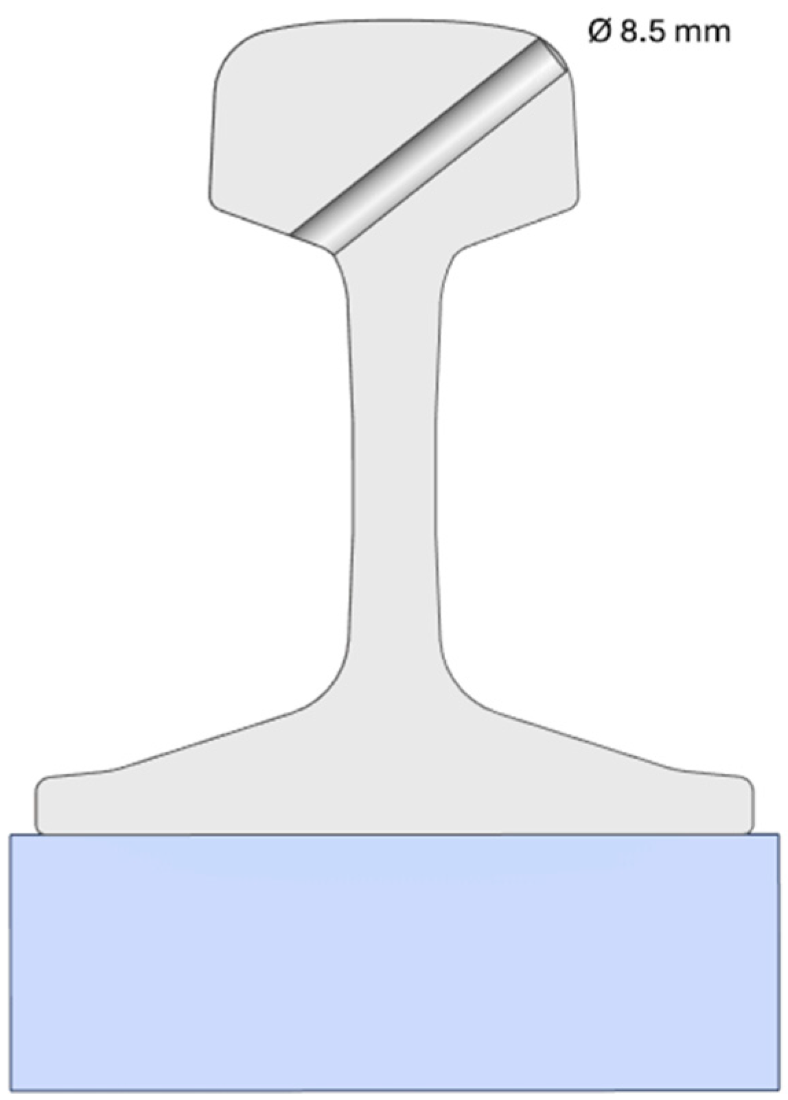
The experimental program was conducted on full-scale rail coupons extracted from standard UIC 54 (54E1) rail profiles manufactured in grade R260 steel. Each coupon had a total length of 800 mm and contained a single lubrication hole drilled in the center of the rail head. The diameter of the hole was 8.5 mm, consistent with those commonly used in operational rail networks, see Figure 1 and Figure 2. All rails were unused and free from visible defects or corrosion prior to testing.
The specimens were tested in an inverted position (i.e., head down), under three-point bending conditions. This configuration was selected based on preliminary tests, which confirmed that tensile stresses at the hole location are more critical when the rail head is in the tension zone. The drilled hole was positioned at the midspan of the coupon, aligned with the load application point, thus representing the most unfavorable fatigue condition.

2.1.2. Fatigue Tests

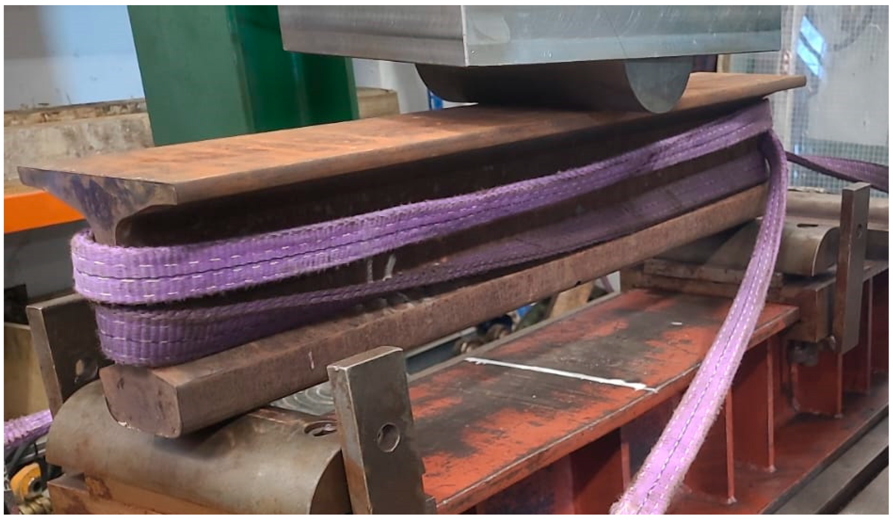
Fatigue tests were performed under load-controlled conditions using a servo-hydraulic testing machine with a maximum capacity of 1000 kN. A three-point bending configuration was adopted with a span of 700 mm between supports. The load was applied vertically at midspan, coinciding with the location of the lubrication hole. Prior to testing, the rail head and support areas were machined to ensure proper seating and avoid unwanted stress concentrations, see Figure 3.
A monotonic fatigue protocol was applied in which each specimen was subjected to a constant-amplitude loading cycle with a fixed maximum force. The stress ratio was set to R = 0.1, ensuring that the outer fiber of the rail head—located in the tension zone due to the inverted setup—remained under tensile stress throughout the entire cycle. This configuration was intentionally selected to represent a highly damaging loading condition for the drilled rail, allowing consistent comparison of fatigue strength across specimens. The frequency of cycling was set to 5 Hz. Each test consisted of two phases: an initial phase of 105 cycles to simulate early fatigue damage, followed by continued cycling at the same load level until failure or until a limit of 3 × 10⁶ cycles was reached.
The number of cycles to failure was recorded for each specimen, and the results were used to construct the experimental S–N curve. After failure, the fracture surfaces were visually inspected and documented. In selected cases, scanning electron microscopy (SEM) was used to qualitatively identify the location and nature of crack initiation near the hole edge.

2.2. Finite Element Modeling

To complement the experimental results and gain further insight into the fatigue behavior of drilled rails, two finite element models were developed using ANSYS Workbench. The first model, referred to as Model 1, replicates the laboratory testing configuration and was used for numerical calibration based on the experimental S–N curve. The second, Model 2, represents a more realistic track segment composed of multiple spans and includes a moving wheel load to simulate operational conditions. Both models were developed with attention to geometric fidelity, mesh refinement in critical areas, and realistic boundary conditions. Fatigue analysis was carried out using the stress–life (S–N) approach, with a focus on the hole edge, which acts as the primary crack initiation site. This modeling strategy allows both validation against laboratory results and exploration of design variables that cannot be easily tested experimentally.

2.2.1. Model 1—Reduced Geometry

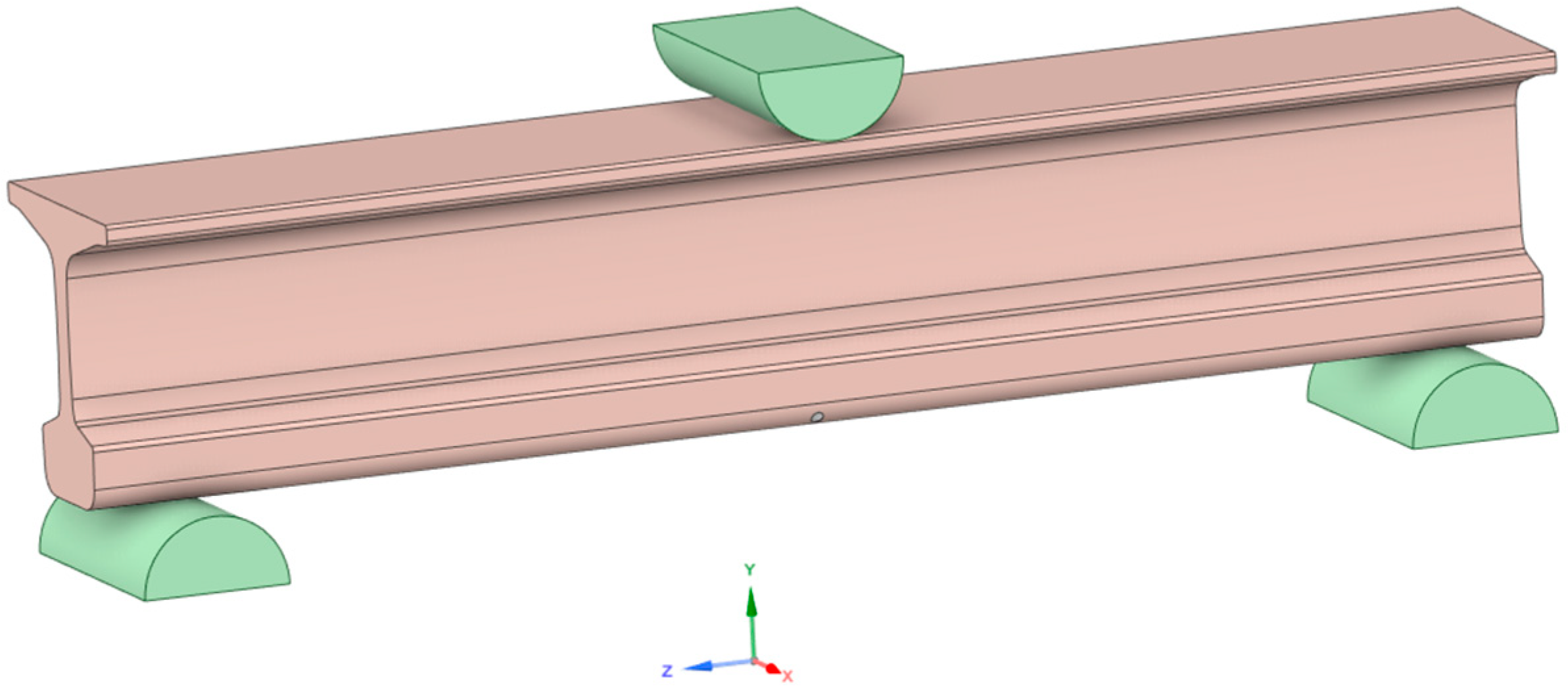
A reduced finite element model was developed to replicate the experimental three-point bending configuration described in Section 2.1.2. The geometry was constructed based on the actual dimensions of the tested rail coupons (UIC 54 profile, 800 mm in length) and included a central lubrication hole of 8.5 mm diameter located in the rail head, see Figure 4. The supports and loading head were also modeled to represent the boundary conditions and contact areas used in the physical tests.
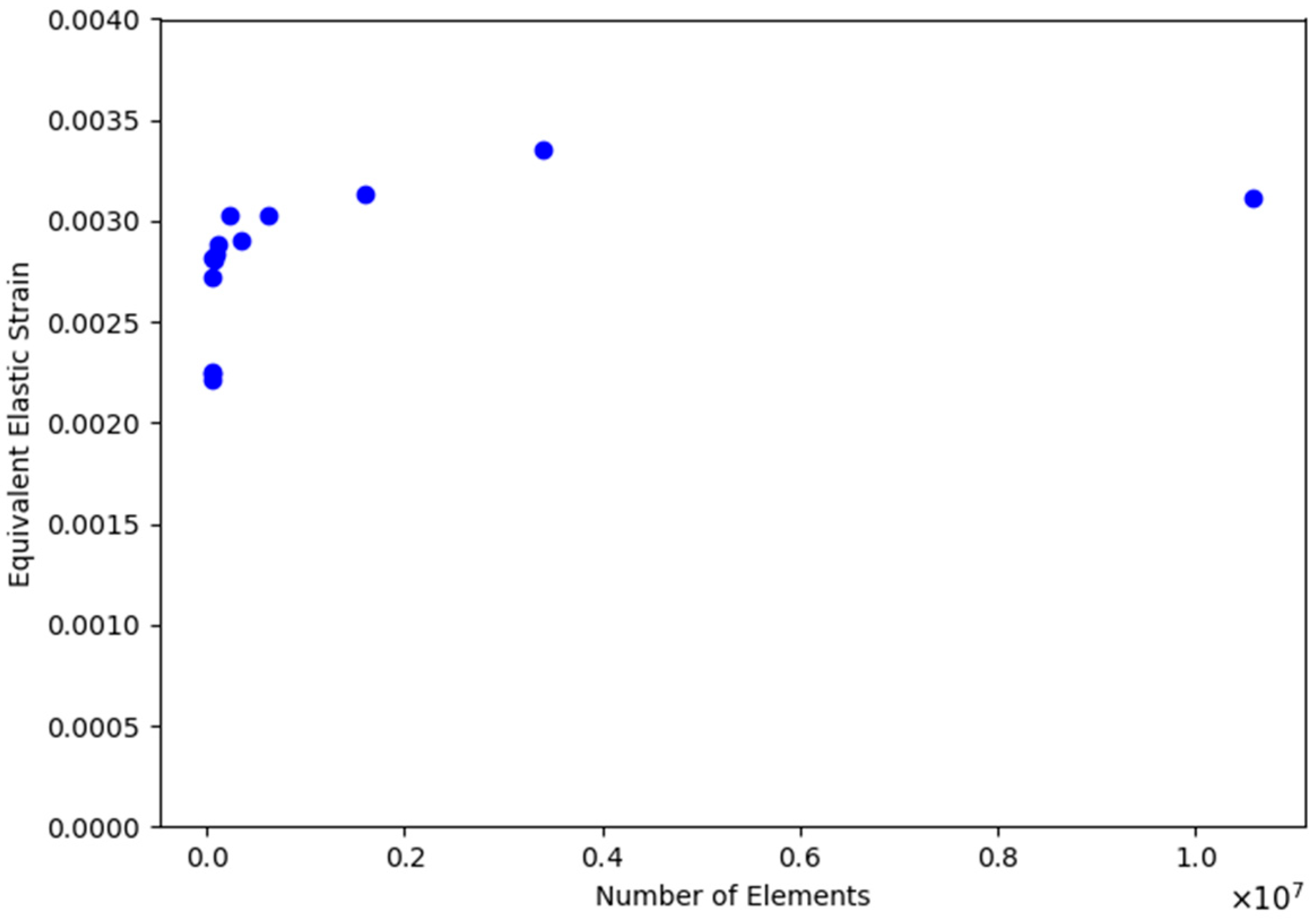
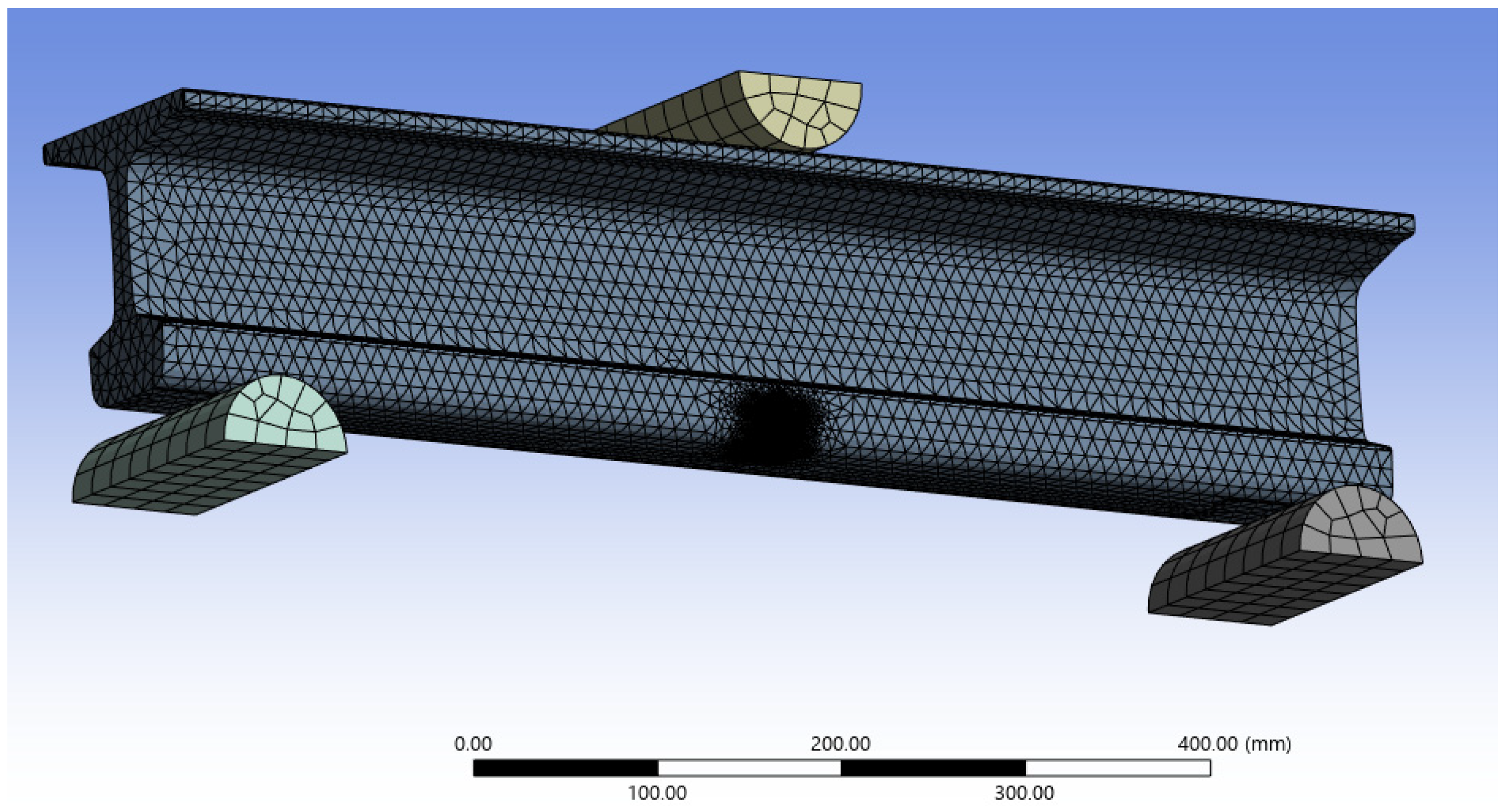
A finite element mesh composed of tetrahedral elements was employed, as this type of element offers improved geometric fidelity and higher accuracy in the estimation of stress and strain fields, particularly in regions with pronounced geometric gradients. To support the numerical model, a mesh convergence analysis was conducted, as illustrated in Figure 5. The analysis evaluates the variation of stress at the hole location across multiple mesh densities, confirming that the solution stabilizes with mesh refinement. The final mesh configuration, consisting of approximately 1,600,000 elements, was selected as it provides an optimal compromise between computational efficiency and the accuracy of the results.
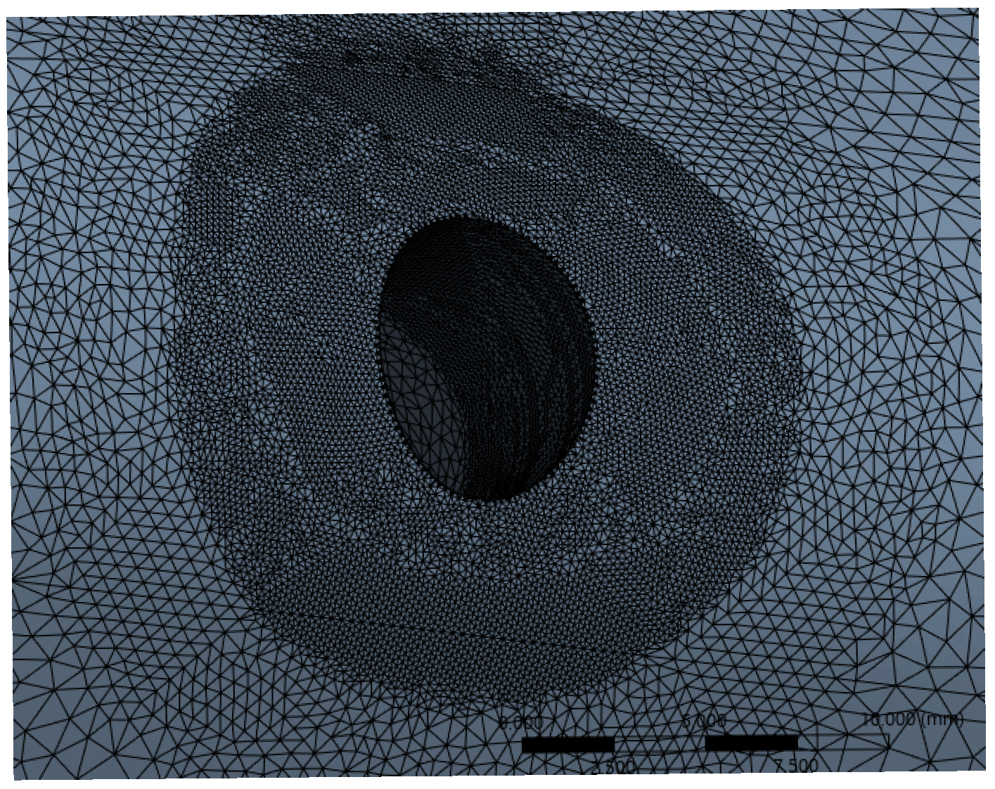
The model was meshed with a local refinement applied in the vicinity of the hole to capture the high stress gradients that govern fatigue initiation, see Figure 6 and Figure 7. The remainder of the domain was discretized with a coarser but regular mesh to optimize computational efficiency. All elements were assumed to behave in the linear elastic regime. The material properties assigned to the rail steel were as follows: Young’s modulus E = 210 GPa, Poisson’s ratio ν = 0.3, yield strength σy = 597 MPa, and ultimate tensile strength σu = 961 MPa. The S–N curve used for the fatigue analysis is presented in Table 1.
A load-controlled static analysis was first carried out to verify that the stress field reproduced the expected bending behavior under the applied force levels. Subsequently, fatigue analysis was performed using the ANSYS fatigue module based on the stress–life (S–N) approach. A stress ratio of R = 0.1 was applied, and the Goodman correction was used to account for mean stress effects. The fatigue strength coefficient kf was calibrated iteratively by fitting the numerical predictions to the experimental S–N data. The fatigue life was evaluated at nodes located on the internal surface of the hole, where experimental fracture typically initiated.

2.2.2. Model 2—Full Track Section

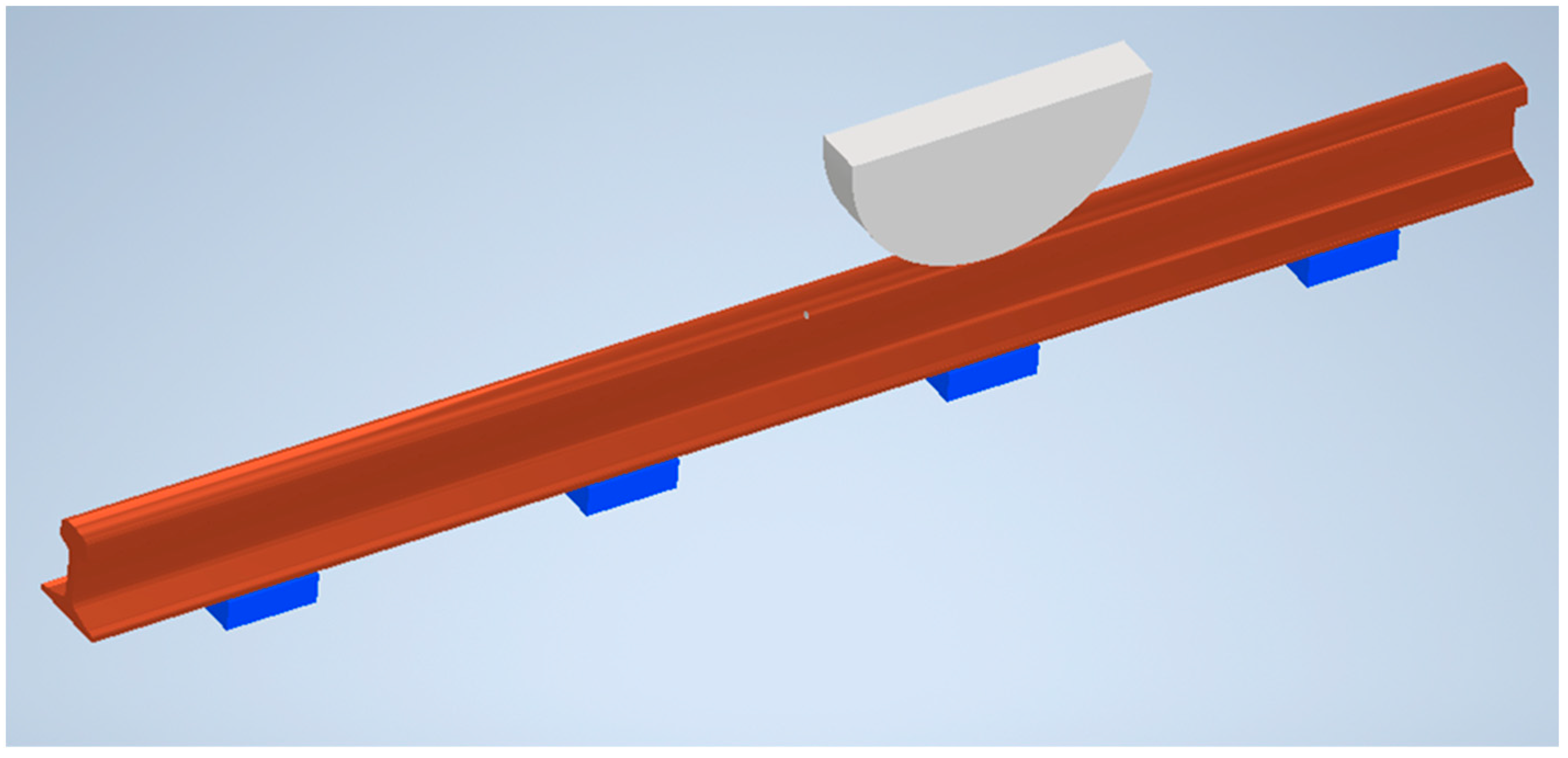
A second finite element model was developed to simulate a more realistic rail track segment under operational conditions. This model consists of a rail section spanning three full bays and two half bays, representing a continuous track system with periodic support conditions, see Figure 8. The total length of the model was selected to ensure that local effects from wheel loading and boundary conditions would not influence the region of interest. The rail profile corresponds to UIC 54 (grade R260), and the supports were modeled as rigid blocks spaced at 600 mm intervals, consistent with typical in-service configurations. This spacing reflects the standard distance between sleepers (ties) in metro track systems.
A single lubrication hole was introduced in the rail head, and its position was varied parametrically along the span in three different locations: (i) at midspan, (ii) at one-quarter span, and (iii) directly above a support. Similarly, three different hole diameters were considered: 5 mm, 8.5 mm (reference value), and 12 mm. To evaluate the impact of wheel position, a vertical point load representing a railway wheel was applied at multiple locations along the rail. The wheel diameter was assumed to be 500 mm, and the contact was modeled as a vertical force distributed over a 20 mm length to approximate the contact patch.
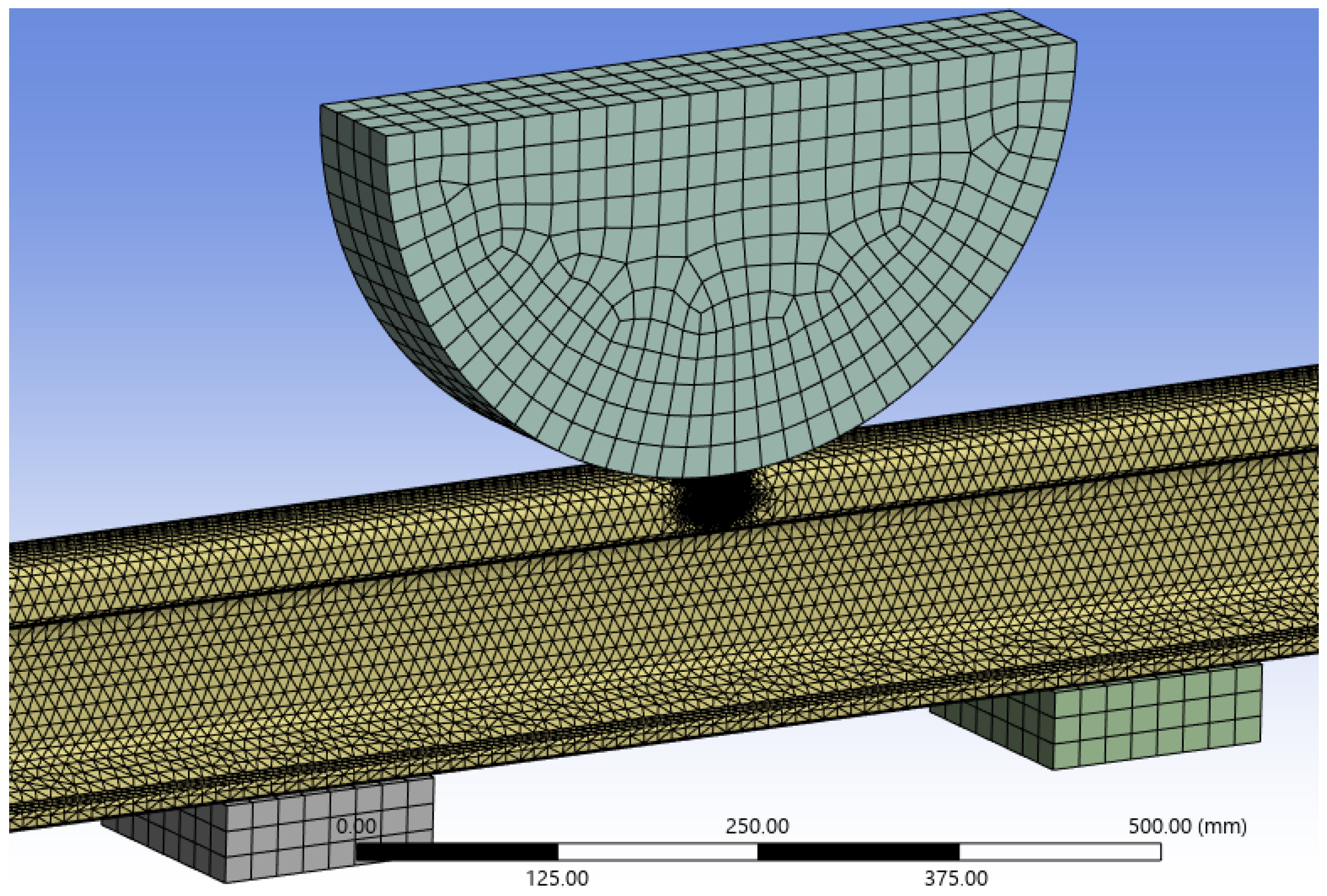
The model was discretized using tetrahedral elements, with local mesh refinement applied around the hole and beneath the moving load to accurately capture the stress gradients relevant to fatigue initiation, see Figure 9. A linear elastic material model was used, and the same material properties as those defined in Section 2.2.1 were assigned to the rail steel. For each configuration, a static structural analysis was first performed to compute the stress distribution under the applied load. Fatigue analysis was then carried out using the stress–life (S–N) approach, applying a stress ratio R = 0.1 and incorporating the Goodman correction to account for mean stress effects. The fatigue life was evaluated at nodes located on the internal surface of the hole, and the minimum number of cycles to failure across all loading positions was extracted for each configuration.
Special care was taken to ensure full consistency between the full-track model and the previously calibrated reduced model. Both models share the same material definition, fatigue parameters, and meshing strategy, including refinement in high-stress regions. Moreover, the fatigue assessment procedures were identical in both cases, ensuring that the fatigue life predictions from the full-track simulations could be directly compared with the experimentally validated results from the reduced setup.
The objective of this numerical phase was twofold: first, to assess whether the current configuration of the lubrication hole lies on the safe side regarding fatigue performance under service conditions; and second, to define a set of design guidelines regarding the optimal hole diameter and its position relative to the track supports. To this end, each structural detail—defined as a specific combination of hole diameter and hole location—was independently analyzed.
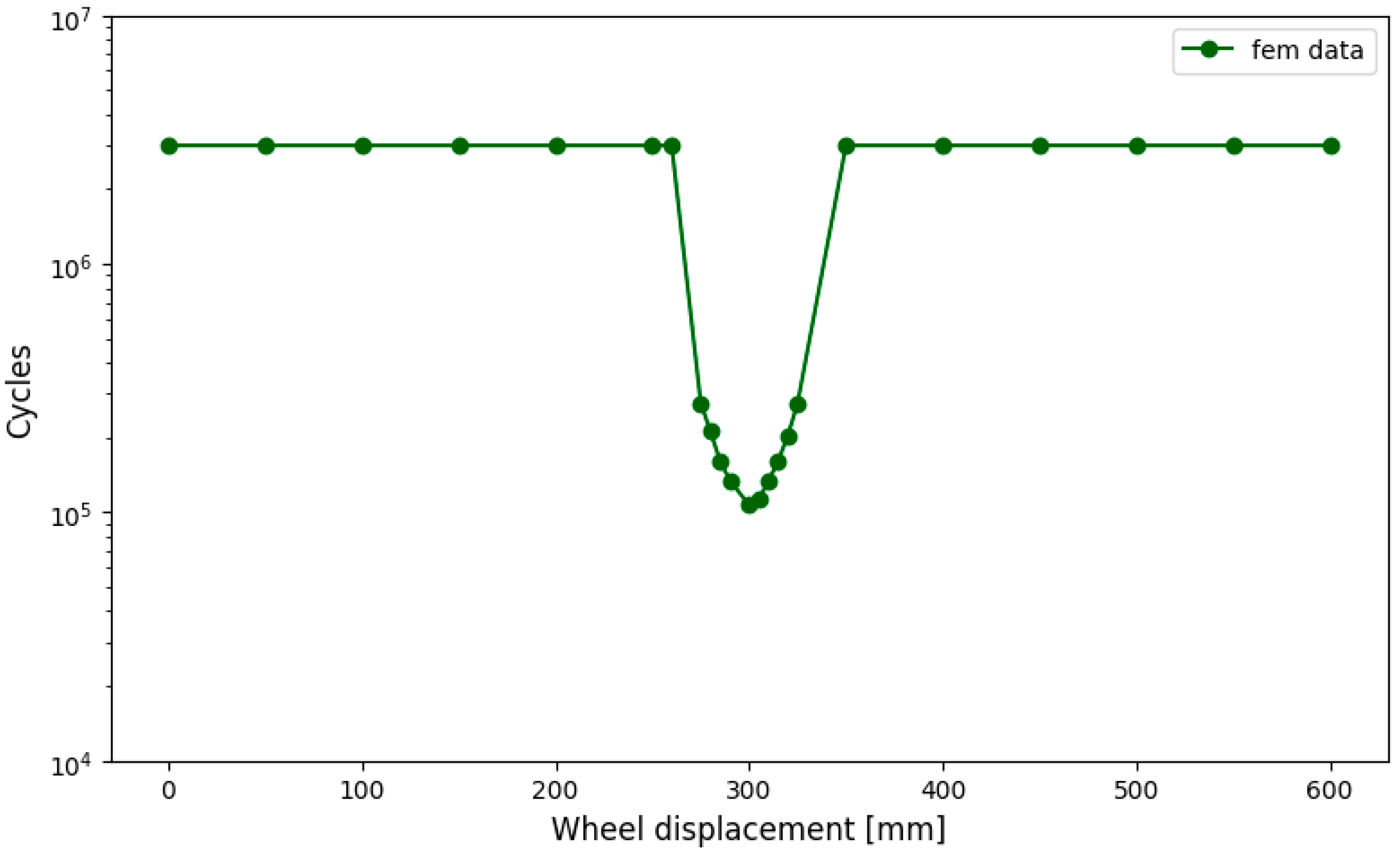
For each configuration, a moving wheel load was simulated along the full length of the rail. This allowed the identification of the most critical loading position, as it is not known a priori where the applied load will lead to the lowest fatigue life [16]. The minimum number of cycles to failure obtained during this sweep was used to define the most unfavorable fatigue condition for each case, see Figure 10.
In order to account for the influence of wheel passage along the rail, a quasi-static load sweep was performed in the full-track model. The wheel load was incrementally displaced along the rail axis, and for each position, the stress field at the lubrication hole was evaluated. This procedure enabled the identification of the most critical wheel location—i.e., the position that generates the lowest fatigue life—thus capturing the effect of variable bending conditions due to wheel movement without requiring a transient dynamic simulation.
Using these worst-case values, an S–N curve was generated for each structural configuration by repeating the simulation under various load magnitudes. This enabled a comparative analysis of fatigue performance between different design alternatives. The influence of both hole diameter and hole location was assessed by comparing the resulting S–N curves. An example of the fatigue life evolution along the rail, as a function of wheel position, is presented in Figure 10 which illustrates how the critical loading point shifts depending on the geometry and loading scenario.

3. Results

This section presents the results obtained from both the experimental tests and the numerical simulations described above. First, the fatigue life predictions from the reduced finite element model (Model 1) are compared against the experimental S–N data to validate the numerical approach. Once validated, the full-track model (Model 2) is used to carry out a parametric study, assessing the influence of wheel position, hole diameter, and hole location on the fatigue life of the rail. The results are analyzed in terms of the number of cycles to failure at the hole surface, which has been identified as the most critical zone for crack initiation.

3.1. Experimental Results

The fatigue life of the rail under inverted loading conditions was experimentally characterized by subjecting multiple specimens to constant-amplitude loading until failure. The number of cycles to failure recorded for each load level is summarized in Table 2. These data were used to construct the experimental S–N curve, which serves as a reference for the subsequent numerical calibration.
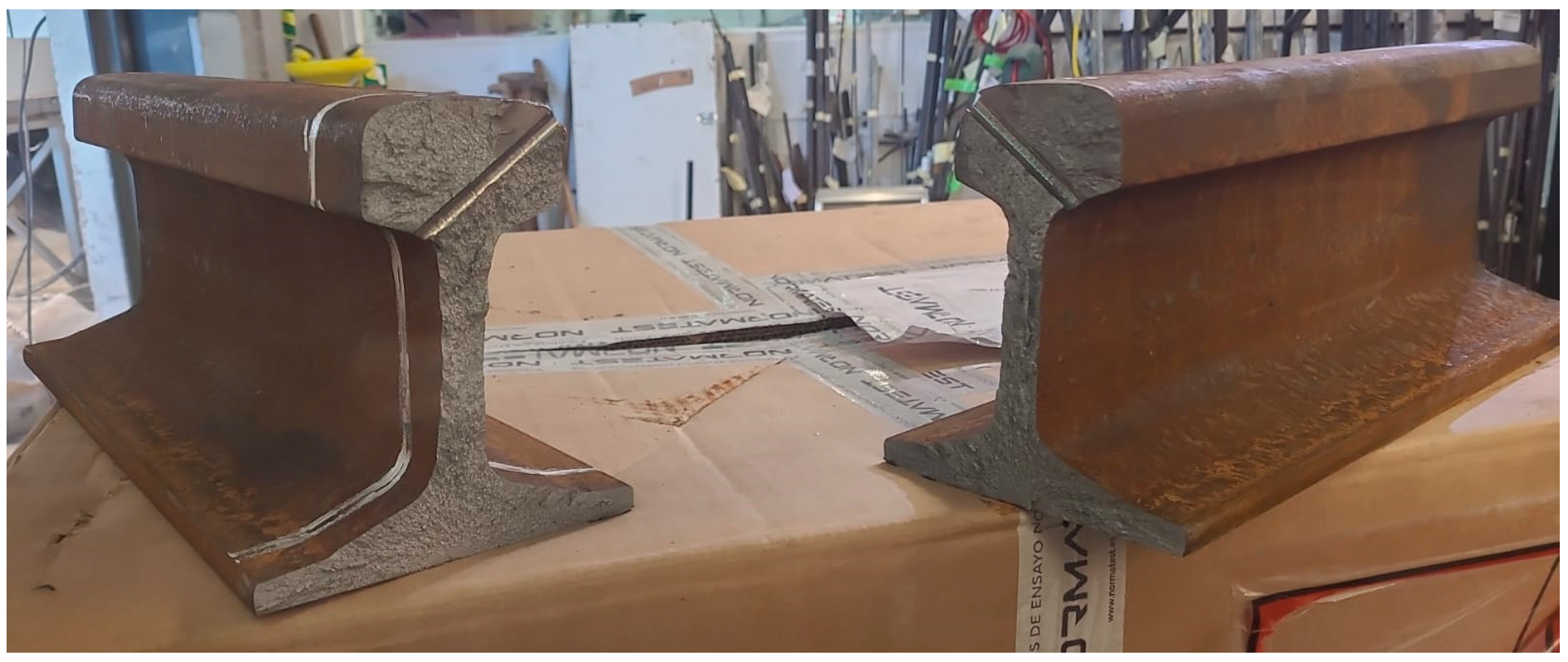
After failure, the fracture surfaces of the specimens were examined to verify the location and nature of crack initiation. As expected, all cracks initiated at the inner surface of the lubrication hole and propagated across the rail head. Figure 11 shows a representative appearance of a failed specimen after testing. In addition, a detailed view of one fracture surface is provided in Figure 12, highlighting the region affected by fatigue crack growth. The characteristic surface texture and propagation front confirm that fatigue was the dominant failure mechanism in this zone.

3.2. Experimental vs. Numerical S–N Comparison (Model 1)

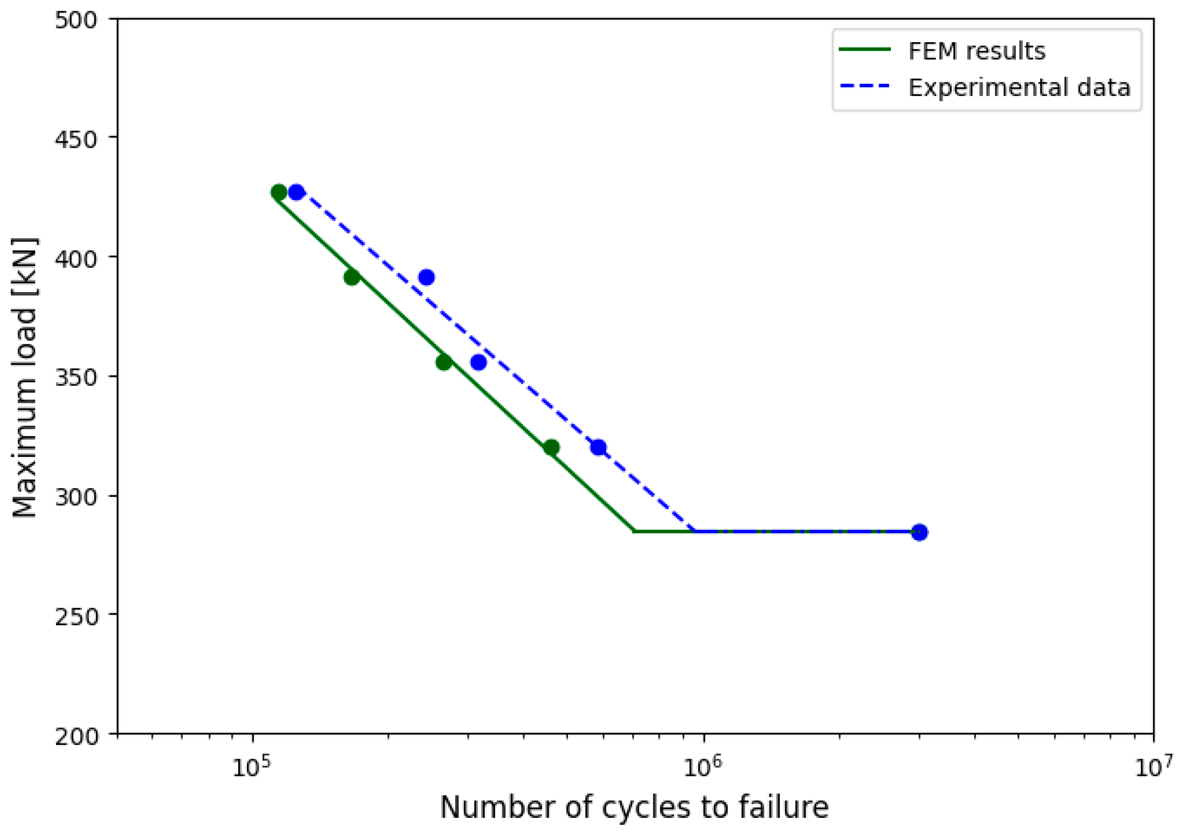
The comparison between the experimental and numerical fatigue life results is presented in Figure 13, where the number of cycles to failure obtained from laboratory tests is plotted alongside the predictions from the reduced finite element model described in Section 2.2.1. The numerical results were obtained using the same loading conditions and S–N curve definition as in the experimental campaign, with fatigue life evaluated at the inner surface of the lubrication hole.
A good agreement can be observed between the experimental data and the numerical predictions across the entire range of applied stress amplitudes. This correlation confirms the adequacy of the modeling assumptions and validates the use of the reduced model for fatigue life estimation under the tested conditions.
Based on these results, the finite element framework is considered sufficiently accurate and robust. Therefore, the same modeling parameters, including material properties, meshing strategy, and fatigue criteria, were transferred to the full-track model in order to extract further insights on the influence of geometric and loading variables in more realistic configurations.

3.3. Parametric Study (Model 2)

The results obtained from the full-track finite element model are presented in this section, focusing on the influence of key geometric variables on rail fatigue performance. The parametric study has been structured in two distinct parts.
The first part evaluates the effect of the hole diameter on fatigue life, keeping the hole location fixed at rail support, ¼ rail span, or rail midspan, and analyzing the resulting fatigue response for diameters of 5 mm, 8.5 mm, and 12 mm.
The second part investigates the influence of the hole position along the rail span. In this case, the diameter was kept constant at the values of 5, 8.5, or 12 mm, and the hole was placed in three different positions: midspan, one-quarter span, and directly above a support.
For each configuration, the wheel load was moved incrementally along the rail to identify the most critical loading position leading to minimum fatigue life. The corresponding worst-case fatigue life was then used to construct S–N curves for each structural detail, enabling a direct comparison between alternatives.

3.3.1. Influence of Hole Diameter

As previously described, a total of nine configurations were evaluated in the parametric study, resulting from the combination of three hole diameters (5 mm, 8.5 mm, and 12 mm) and three hole locations (midspan, quarter-span, and above a support). This subsection focuses on the influence of hole diameter, analyzing the fatigue life results for each diameter while keeping the hole position fixed.
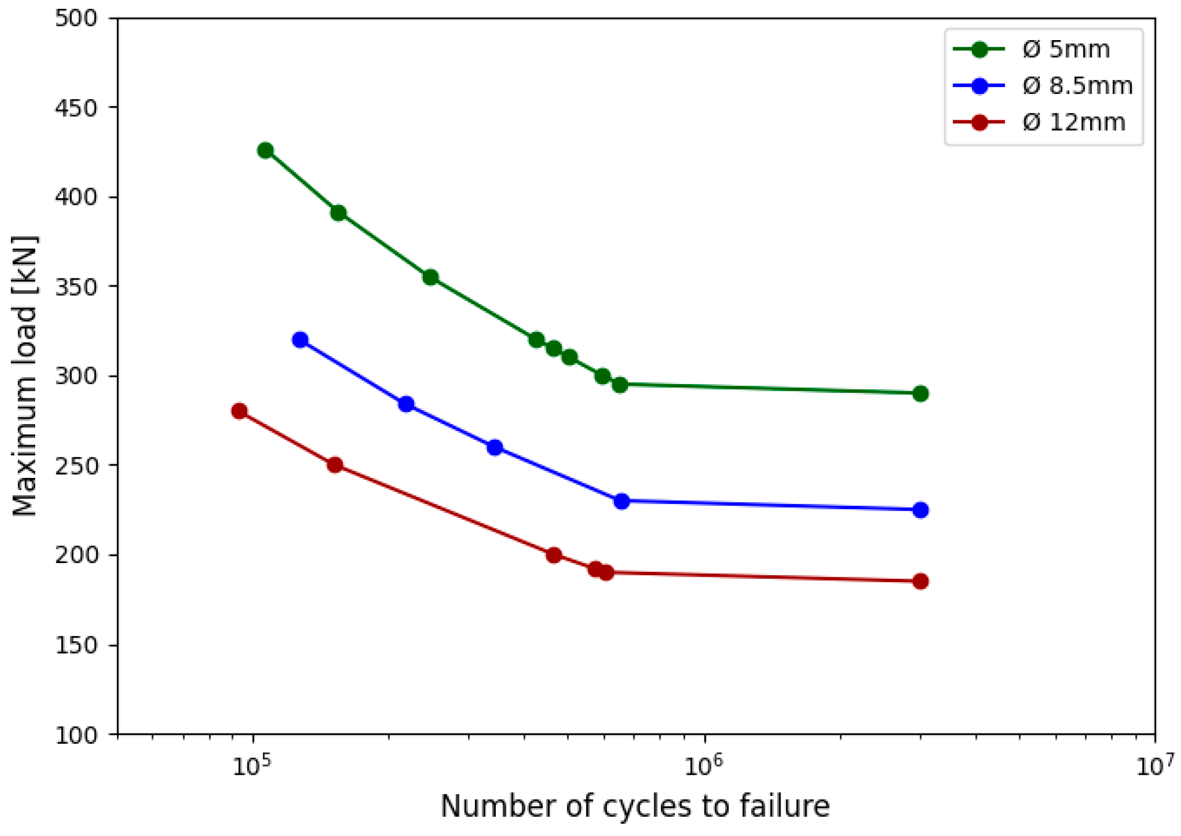
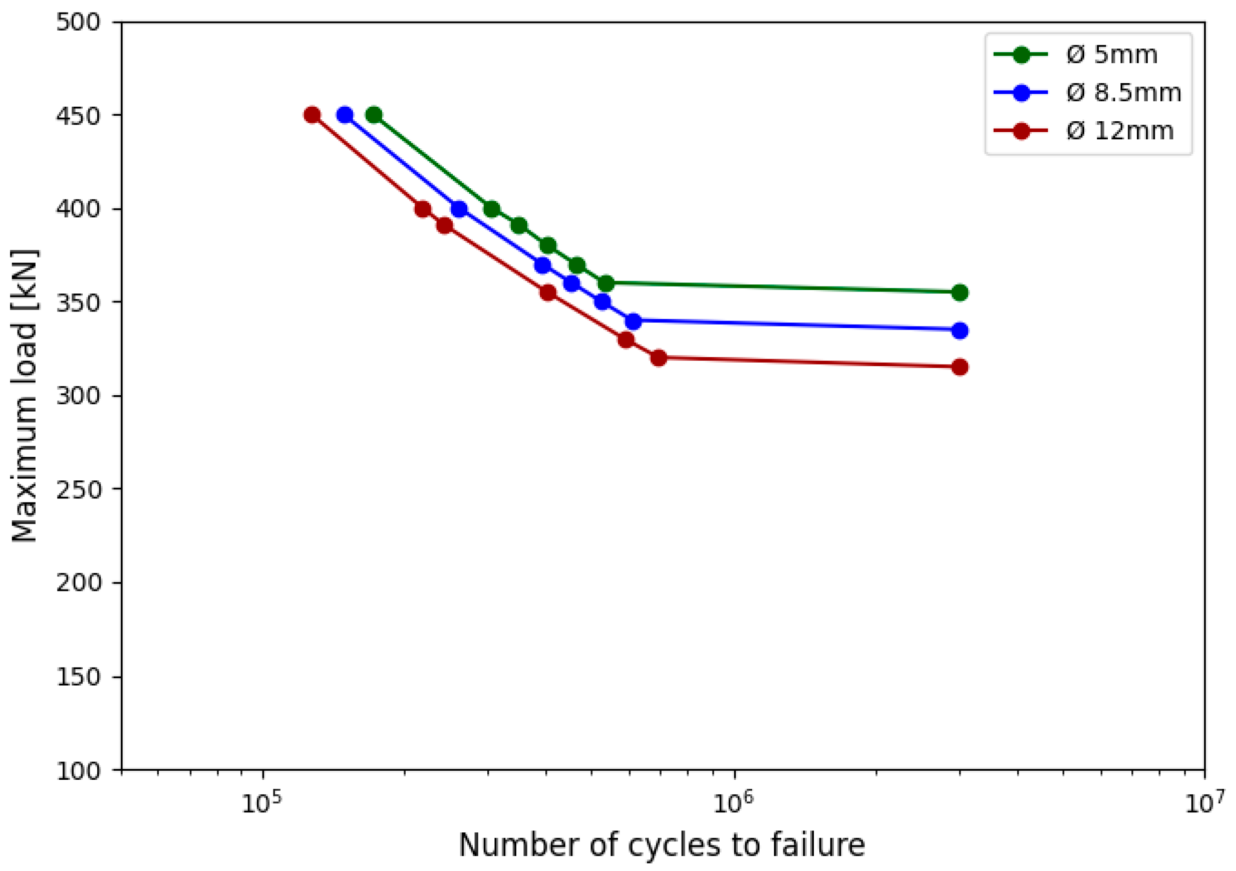
To facilitate interpretation, the results are presented in the form of three separate S–N diagrams, shown in Figure 14, Figure 15 and Figure 16, corresponding to each of the three hole locations. In each figure, the S–N curves obtained from the full-track model are plotted for the three different diameters. This allows a direct comparison of the fatigue behavior associated with hole size under otherwise identical loading and boundary conditions.
These results provide insight into how increasing or reducing the hole diameter affects the fatigue life of the rail and how this effect varies depending on the relative location of the hole within the span.
The results shown in Figure 14, Figure 15 and Figure 16 indicate a consistent trend across all hole locations: As the hole diameter increases, the fatigue life of the rail decreases. For a given load level, the number of cycles to failure is systematically lower for larger diameters. This behavior is observed regardless of the hole position along the span, highlighting the strong influence of geometric discontinuities on fatigue performance. The difference in fatigue life between the 5 mm and 12 mm holes becomes more pronounced at higher stress amplitudes.

3.3.2. Influence of the Hole Position

In this second part of the parametric study, the influence of the hole location on fatigue life is evaluated. To isolate the effect of this variable, the hole diameter was fixed, while the hole position was varied between three characteristic locations along the rail span: midspan, one-quarter span, and directly above a support.
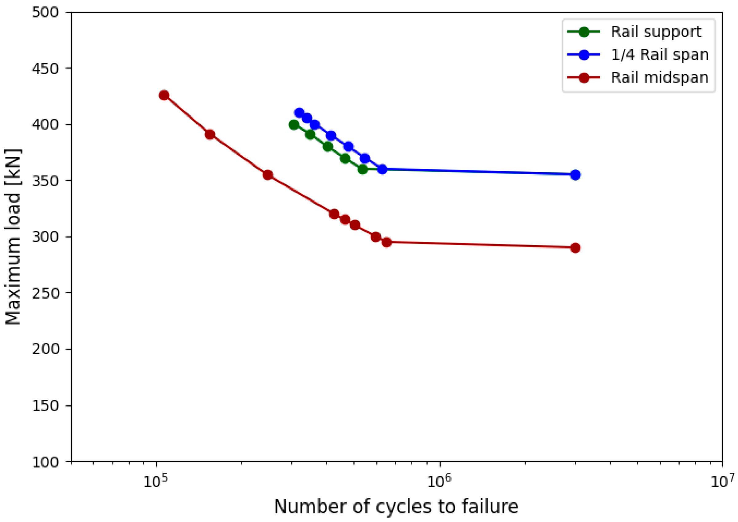
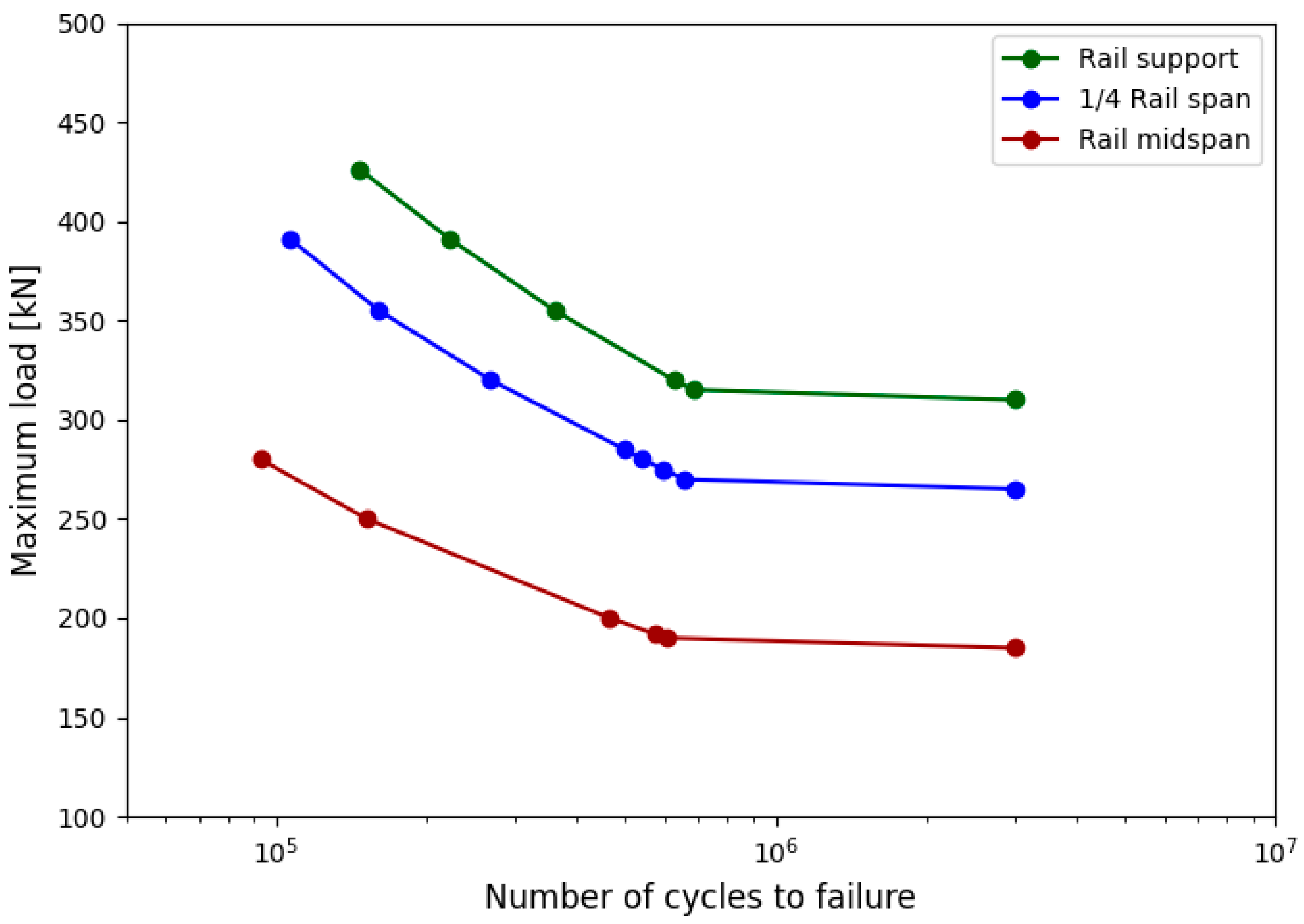
The results are presented in the form of a single comparative S–N diagram, shown in Figure 17, Figure 18 and Figure 19, which includes the fatigue life predictions obtained for the three hole positions under identical loading conditions. As in the previous analysis, for each configuration the wheel load was moved along the rail to identify the most critical position, and the corresponding fatigue life was used to generate the curve.
This comparison enables the assessment of how the relative position of the hole with respect to the support layout affects the stress distribution and fatigue performance, providing valuable input for optimal hole placement in track design.
As shown in Figure 17, Figure 18 and Figure 19, the hole location has a significant impact on the fatigue life of the rail. Among the three configurations analyzed, the midspan position consistently resulted in the lowest number of cycles to failure across the entire range of applied loads. The fatigue performance improved when the hole was placed at one-quarter of the span, and even more so when located directly above a support. These results confirm that the central region of the span is the most critical location for fatigue initiation due to the higher bending moments experienced under typical loading conditions.

4. Discussion

The comparison between experimental results and numerical predictions obtained with the reduced finite element model showed a very strong correlation, confirming the adequacy of the modeling approach. The model successfully reproduced the fatigue life observed in the laboratory across the full range of stress amplitudes, validating the use of the selected material properties, fatigue parameters, and meshing strategy. This validation step provides confidence in the extension of the modeling framework to the full-track simulations.
The parametric study highlighted the strong influence of the hole diameter on the fatigue performance of the rail. Increasing the diameter led to a clear and systematic reduction in the number of cycles to failure, regardless of the hole location. This effect is directly related to the stress concentration generated around the edge of the hole, which becomes more severe as the hole size increases. These results support the need to limit hole diameter where possible, especially in regions of high bending stress.
The location of the hole along the rail span also proved to be a critical factor. Among all configurations tested, placing the hole at the midspan of the beam consistently resulted in the shortest fatigue life, due to the higher bending moments developed under vertical loading. Placing the hole closer to the support region significantly increased the fatigue life, as the local stress field was less severe. This suggests that the relative position of the hole with respect to track supports should be carefully considered in design and maintenance practices.
To enhance the practical applicability of the results, a guideline matrix has been developed and is presented in Table 3. This table summarizes the relationship between the hole diameter and its position within the structure, and the resulting stress concentration levels observed in the simulations.
Importantly, the simulations also demonstrated that, under realistic service loads inferred from in-track measurements, the fatigue life of the current configuration lies well on the safe side. For the standard 8.5 mm diameter hole located at midspan, the predicted fatigue life under typical axle loads exceeded several million cycles. This indicates that the system, as currently designed and used, offers a high safety margin against fatigue failure, even under conservative assumptions such as worst-case wheel positioning.
Additionally, the full-track simulation strategy—where the wheel load was swept along the rail to identify the most critical location—proved to be a valuable tool. It allowed the detection of unfavorable loading conditions that are not evident in simplified test setups and facilitated the construction of fatigue curves representative of worst-case scenarios. This methodology could be extended to assess other types of rail discontinuities, such as drilled sensor ports or localized defects, under more complex loading patterns (e.g., variable amplitude or dynamic effects).

5. Conclusions

This study evaluated the fatigue behavior of railway rails containing lubrication holes through a combined experimental and numerical approach. The main conclusions are as follows:
-
The finite element model developed to reproduce the inverted three-point bending test configuration showed excellent agreement with the experimental S–N curve, validating the numerical methodology for fatigue life prediction in drilled rails.
-
The diameter of the lubrication hole was identified as a key parameter influencing fatigue performance. Larger holes produced significantly lower fatigue life due to increased stress concentration at the hole edge.
-
The position of the hole relative to the track supports also had a notable effect. The midspan location proved to be the most critical, corresponding to the region of maximum bending moment, while holes placed near supports resulted in higher fatigue life.
-
The full-track finite element model, calibrated with experimental data, enabled the identification of the worst-case loading condition for each structural configuration by sweeping the wheel load along the rail. This approach proved effective for constructing conservative S–N curves representing each design scenario.
-
Under realistic service loads, the current design—with an 8.5 mm hole located at midspan—was shown to lie on the safe side, with fatigue lives well above critical thresholds. This provides confidence in the continued use of the existing configuration under current operating conditions.
-
The numerical methodology developed in this study can serve as a reliable predictive tool for assessing the impact of geometric modifications in drilled rails and can be extended to evaluate other discontinuities or loading conditions in future work.

Author Contributions

Conceptualization, R.M., D.P., H.V., J.A.C., I.C. and S.D.; methodology, J.S.-A., P.S.R., D.F., I.C. and B.A.; software, J.S.-A., P.S.R., D.F. and B.A.; validation, R.M., D.P., H.V. and S.D.; formal analysis, J.S.-A., P.S.R., D.F., J.A.C., I.C. and S.D.; investigation, J.S.-A., P.S.R., D.F., J.A.C., I.C., S.D. and B.A.; resources, R.M., D.P. and H.V.; data curation, J.S.-A., P.S.R., D.F. and B.A.; writing—original draft preparation, J.S.-A. and P.S.R.; writing—review and editing, J.S.-A., P.S.R., D.F., J.A.C. and S.D.; project administration, R.M., D.P., H.V., J.A.C., I.C., S.D. and B.A.; funding acquisition, R.M., D.P., H.V., J.A.C., I.C. and S.D. All authors have read and agreed to the published version of the manuscript.

Funding

This research was funded by Metro de Madrid through the Collaboration Agreement for Knowledge Transfer between Metro de Madrid and the Leonardo Torres Quevedo Foundation of the University of Cantabria for the implementation of the R&D project “Study on the Effect of Lubrication Holes in the Rail Head”.

Data Availability Statement

The original contributions presented in this study are included in the article. Further inquiries can be directed to the corresponding author.

Acknowledgments

The authors would like to thank Eurocontrol for providing the coordination and support necessary to conduct this research work.

Conflicts of Interest

Author Raul Moreno, David Peribañez and Hugo Vegas were employed by the company Metro de Madrid, Servicio Superestructura de Vía. The remaining authors declare that the research was conducted in the absence of any commercial or financial relationships that could be construed as a potential conflict of interest.

References

  1. Wang, S.; Wen, B.; Ren, D.; Ding, Y.; Wen, Z.; Dong, D.; Tao, G. Analysis of the causes of severe side wear of the high rail on metro curves by numerical simulation and field investigation. Proc. Inst. Mech. Eng. F J. Rail Rapid Transit. 2024, 238, 381–393. [Google Scholar] [CrossRef]
  2. Li, S.; Li, J.; Wu, B.; Shi, L.; Zhang, S.; Ding, H.; Wang, W.; Liu, Q. Influence of Lubricating Materials on Wheel-Rail Wear and Rolling Contact Fatigue. Mocaxue Xuebao/Tribol. 2022, 42, 935–944. [Google Scholar] [CrossRef]
  3. Milanese, M.; Iacobazzi, F.; Stark, M.; de Risi, A. Development of common rail lube oil injector for large two-stroke marine diesel engines. Int. J. Engine Res. 2022, 23, 1131–1143. [Google Scholar] [CrossRef]
  4. Shu, K.; Zani, N.; Ghidini, L.; Petrogalli, C.; Yu, L.L.; Mazzù, A.; Ding, H.H.; Wang, W.J. Wear and damage behaviors of wheel-rail with different material matchings under various sand deposition densities of rail top in desert environments. Wear 2025, 560–561, 205622. [Google Scholar] [CrossRef]
  5. Fang, X.-Y.; Zhang, H.-N.; Ma, D.-W.; Wu, Z.-J.; Huang, W. Influence of welding residual stress on subsurface fatigue crack propagation of rail. Eng. Fract. Mech. 2022, 271, 108642. [Google Scholar] [CrossRef]
  6. Ringsberg, J.W.; Josefson, B.L. Assessment of uncertainties in life prediction of fatigue crack propagation in welded rails. In Proceedings of the 12th International Conference on Fracture 2009, ICF-12, Ottawa, ON, Canada, 12–17 July 2009; pp. 5837–5846. Available online: https://www.scopus.com/inward/record.uri?eid=2-s2.0-84869811698&partnerID=40&md5=8b1b6660215bb5c9d8e2dc9f26d40741 (accessed on 6 July 2025).
  7. Ma, X.; Wang, Y.; Wang, X.; Yin, W.; Liu, L.; Xu, J. Investigation on fatigue crack propagation behaviour of U71Mn and U75V rails using peridynamics. Eng. Fract. Mech. 2023, 281, 109097. [Google Scholar] [CrossRef]
  8. Boyacioglu, P.; Bevan, A. Rail surface damage management through monitoring and modelling. Int. J. Rail Transp. 2025, 13, 231–247. [Google Scholar] [CrossRef]
  9. Maximov, J.T.; Duncheva, G.V.; Amudjev, I.M.; Anchev, A.P.; Ganev, N. A new approach for pre-stressing of rail-end-bolt holes. Proc. Inst. Mech. Eng. C J. Mech. Eng. Sci. 2017, 231, 2275–2283. [Google Scholar] [CrossRef]
  10. Nejad, R.M.; Shariati, M.; Farhangdoost, K. Prediction of fatigue crack propagation and fractography of rail steel. Theor. Appl. Fract. Mech. 2019, 101, 320–331. [Google Scholar] [CrossRef]
  11. Hassani-Gangaraj, S.M.; Carboni, M.; Guagliano, M. Finite element approach toward an advanced understanding of deep rolling induced residual stresses, and an application to railway axles. Mater. Des. 2015, 83, 689–703. [Google Scholar] [CrossRef]
  12. Eden, H.C.; Garnham, J.E.; Davis, C.L. Influential microstructural changes on rolling contact fatigue crack initiation in pearlitic rail steels. Mater. Sci. Technol. 2005, 21, 623–629. [Google Scholar] [CrossRef]
  13. Pucillo, G.P.; Carrabs, A.; Cuomo, S.; Elliott, A.; Meo, M. Cold expansion of rail-end-bolt holes: Finite element predictions and experimental validation by DIC and strain gauges. Int. J. Fatigue 2021, 149, 106275. [Google Scholar] [CrossRef]
  14. Xu, X.; Xie, L.; Zhou, S.; An, J.; Huang, Y.; Li, D. Fatigue Crack Propagation Behavior and Life Prediction of Welded Joints of SMA490BW Steel for Bogies. Processes 2023, 11, 1984. [Google Scholar] [CrossRef]
  15. Ferreño, D.; Casado, J.A.; Carrascal, I.A.; Diego, S.; Ruiz, E.; Saiz, M.; Sainz-Aja, J.A.; Cimentada, A.I. Experimental and finite element fatigue assessment of the spring clip of the SKL-1 railway fastening system. Eng. Struct. 2019, 188, 553–563. [Google Scholar] [CrossRef]
  16. Duncheva, G.V.; Maximov, J.T. A new approach to enhancement of fatigue life of rail-end-bolt holes. Eng. Fail. Anal. 2013, 29, 167–179. [Google Scholar] [CrossRef]
  17. Alshoaibi, A.M. Numerical Modeling of Crack Growth under Mixed-Mode Loading. Appl. Sci. 2021, 11, 2975. [Google Scholar] [CrossRef]
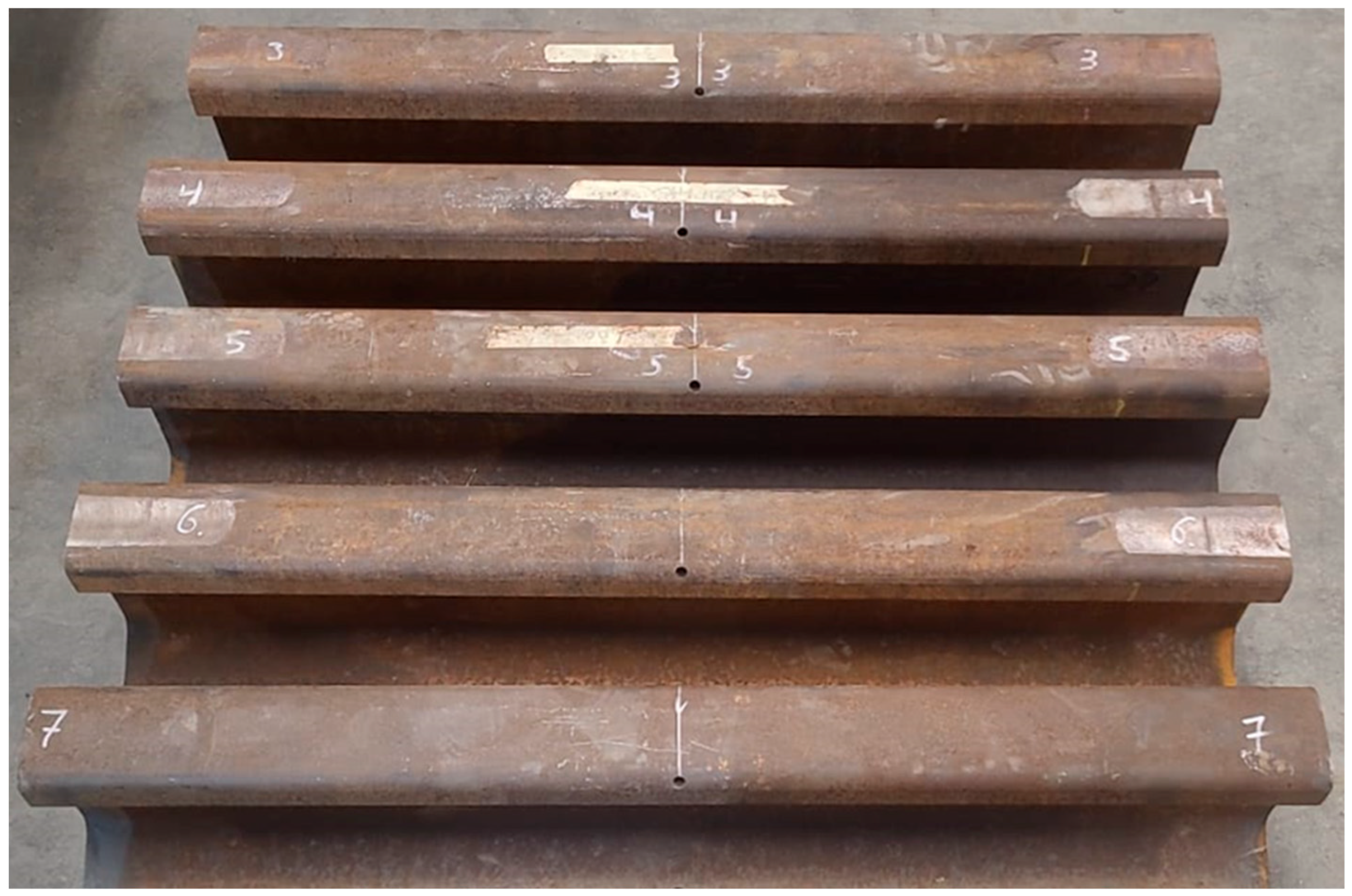
Figure 1. Set of full-scale rail specimens prepared for fatigue testing. All specimens feature a central lubrication hole drilled in the rail head, which serves as the fatigue initiation site under inverted bending conditions.
Metals 15 00992 g001
Figure 2. Cross-section of the rail showing the location and inclination of the lubrication hole. The hole, with a diameter of 8.5 mm, is drilled diagonally through the rail head to reach the wheel–rail contact interface.
Metals 15 00992 g002
Figure 3. Experimental setup used for the inverted three-point bending fatigue tests on full-scale rail specimens. The drilled rail is supported at both ends and subjected to cyclic loading at midspan to replicate service-like bending conditions.
Metals 15 00992 g003
Figure 4. Reduced model geometry.
Metals 15 00992 g004
Figure 5. Mesh convergence analysis based on the von Mises stress evaluated at the hole location for different mesh densities.
Metals 15 00992 g005
Figure 6. Reduced model mesh.
Metals 15 00992 g006
Figure 7. Reduced model mesh detail.
Metals 15 00992 g007
Figure 8. Continuous rail model.
Metals 15 00992 g008
Figure 9. Reduced full model mesh.
Metals 15 00992 g009
Figure 10. Example of fatigue life variation along the rail as a function of wheel position for a given hole diameter and location. The minimum corresponds to the most critical loading configuration used to construct the S–N curve.
Metals 15 00992 g010
Figure 11. Representative appearance of a rail specimen after fatigue failure under inverted three-point bending.
Metals 15 00992 g011
Figure 12. Detail of a fracture surface showing the region of fatigue crack growth originating at the edge of the lubrication hole. The propagation front and surface features confirm the presence of fatigue damage.
Metals 15 00992 g012
Figure 13. Comparison between experimental and numerical S–N curves for the inverted rail fatigue tests.
Metals 15 00992 g013
Figure 14. S–N curves obtained for different hole diameters (5 mm, 8.5 mm, and 12 mm) with the hole located at midspan.
Metals 15 00992 g014
Figure 15. S–N curves obtained for different hole diameters (5 mm, 8.5 mm, and 12 mm) with the hole located at ¼ rail span.
Metals 15 00992 g015
Figure 16. S–N curves obtained for different hole diameters (5 mm, 8.5 mm, and 12 mm) with the hole located at rail support.
Metals 15 00992 g016
Figure 17. S–N curves obtained for different hole positions (rv) with the hole diameter of 5 mm.
Metals 15 00992 g017
Figure 18. S–N curves obtained for different hole positions (rail support, ¼ rail span, and rail midspan) with the hole diameter of 8.5 mm.
Metals 15 00992 g018
Figure 19. S–N curves obtained for different hole positions (rail support, ¼ rail span, and rail midspan) with the hole diameter of 12 mm.
Metals 15 00992 g019
Table 1. Rail steel S–N curve.
Number of Cycles to Failure [N]Stress [MPa]
80,000500
160,000390
280,000330
600,000270
700,000260
3,000,000 (run-out)260
Table 2. Number of cycles to failure recorded for each applied load level under inverted three-point bending fatigue tests.
Lab TestMax. Stress [MPa]Stress Amplitude [MPa]Number of Cycles
CAR-3258232125.450
CAR-4235212244.000
CAR-5214193316.412
CAR-6193174586.313
CAR-7171154>3.000.000
Table 3. Guideline matrix correlating hole diameter and position with stress concentration level (high, moderate, low).
Rail Support¼ Rail SupportRail Midspan
Ø 12 mmLowModerateHigh
Ø 8.5 mmLowLowModerate
Ø 5 mmLowLowLow
Disclaimer/Publisher’s Note: The statements, opinions and data contained in all publications are solely those of the individual author(s) and contributor(s) and not of MDPI and/or the editor(s). MDPI and/or the editor(s) disclaim responsibility for any injury to people or property resulting from any ideas, methods, instructions or products referred to in the content.