Abstract
As the transport of gaseous hydrogen and its use as a low carbon-footprint energy vector become increasingly likely scenarios, both the scientific literature and technical standards addressing the compatibility of pipeline steels with high-pressure hydrogen environments are rapidly expanding. This work presents a detailed review of the most relevant hydrogen embrittlement testing methodologies proposed in standards and the academic literature. The focus is placed on testing approaches that support design-oriented assessments, rather than simple alloy qualification for hydrogen service. Particular attention is given to tensile tests (conducted on smooth and notched specimens), as well as to J-integral and fatigue tests performed following the fracture mechanics’ approach. The influences of hydrogen partial pressure and deformation rate are critically examined, as these parameters are essential for ensuring meaningful comparisons across different studies.
1. Introduction
In the decarbonization process, which is currently leading the energy system toward a drastic reduction in anthropogenic CO2 emissions, hydrogen plays an important role as energy carrier, especially for applications where electricity cannot be used. In a first technological transition phase, the possibility of introducing hydrogen into already existing natural gas (NG) transportation and distribution networks in small percentages is currently a study subject. When hydrogen production and demand scale up, the construction of networks dedicated exclusively to this fuel is also envisaged. Nevertheless, when equal pressure and temperature are considered, the same volume of gaseous hydrogen provides less than one-third of the energy provided by natural gas (from thermodynamic considerations). Therefore, with all operating parameters being equal the energy efficiency of a gas transportation network should suffer a 68–70% reduction in efficiency when compared to natural gas.
There are two ways to fill this gap: increasing the flow speed and/or increasing the transport pressure; obviously, this second option is not available in a possible conversion of existing gas networks to hydrogen, as the hoop stresses that develop on the pipeline walls are directly proportional to the gas pressure, and the natural gas transport pipelines are already working close to the safety limits permitted by regulation.
Among the problems that must be addressed in this transition to gaseous hydrogen as energy vector, there is the evaluation of the hydrogen compatibility of metallic materials used for storage, transportation, and distribution of gaseous mixtures containing hydrogen in any percentage; in fact, it is well known that the atomic hydrogen produced by the dissociation of the H2 molecule on the metal surface, given its very small size and electronic structure, is capable of penetrating the metal, diffusing into it, interacting with the microstructure of the material, and causing its embrittlement [1,2,3,4,5,6].
Nevertheless, the handling of high-pressure gaseous hydrogen is nothing new for the chemical and petrochemical industry, already with a commendable experience in making and operating pure hydrogen vessels and pipelines. As a matter of fact, the worldwide hydrogen production for chemical purposes is currently in the order of magnitude of 1 × 10¹² m3 every year (94 Mt/year) [7], with no specific problems arising. However, when the ASME B31.12 [8] Standard was published in 2009, Hayden highlighted in its publications [9,10] two very important details: on the one hand, all the steels used in this industry are low grades, typically SA-106 Gr. B, API 5L X42 and X52, thus with a Specified Minimum Yield Strength (SMYS) ≤ 52 ksi (360 MPa), while on the other hand the applied stresses are low, up to 30–50% of the SMYS.
However, due to the lower efficiency of hydrogen as energy vector as mentioned before, there is the need to employ higher steel grades and higher utilization factors as well to balance these limitations. Yet, hydrogen is well-known for its tendency to embrittle metallic alloys once it diffuses into the metal lattice. This phenomenon, referred to as hydrogen embrittlement (HE), was first documented by Johnson in 1875 [11]. Johnson observed that steel wires exposed to acidic environments experienced a significant reduction in both the required amount of bends to failure and the strain at failure. Remarkably, the mechanical properties of the wires were fully restored after several hours of exposure to an inert environment at room temperature. Although hydrogen was correctly identified as the cause of this behavior, the underlying mechanisms of embrittlement remained unknown and unformulated at the time.
Over the past century, hydrogen embrittlement has been the subject of extensive research, with nearly 40,000 publications dedicated to this topic [12]. This body of work highlights both the complexity and the engineering significance of hydrogen–metal interactions.
Today, it is common knowledge that gaseous hydrogen embrittles carbon and low-alloy steels, which are the backbone of the NG transport and distribution network, not developing specific failure phenomena such as for “sour” environments, but rather facilitating other fracture mechanisms such as fatigue or fracture under static loading in presence of a pre-existing defect. Nevertheless, as the specific literature body is thriving and the standardization bodies are trying to catch-up, assessing the suitability of various materials for pipelines or pressure vessels intended for hydrogen service is still a complex task. This complexity arises primarily from the lack of a universally accepted standard test for evaluating hydrogen compatibility.
Existing international standards provide different testing methodologies, which can sometimes yield contradictory results. Additionally, the scientific literature presents a variety of test methods, each emphasizing different aspects of hydrogen-related embrittlement phenomena. Even within a single type of test, numerous parameters can influence the results. The test environment, for instance, may consist of pure hydrogen gas at varying pressures [13,14], mixtures of hydrogen and natural gas in different proportions [15,16], or an aqueous hydrogenating medium of varying composition combined with the application of cathodic current [17,18,19]. Specimens may be pre-charged with hydrogen, either through exposure to a pressurized gaseous environment [20,21] or via electrochemical methods [22,23]. Furthermore, test parameters, particularly the strain rate, can vary significantly across a wide range, further complicating the direct comparisons of results. It is also important to note that gas containment and transport equipment predominantly consist of welded structures. As such, the behavior of welded joints should also be evaluated, taking into account the various welding techniques used in pipeline construction. Welds may be formed without filler metal, such as in electric resistance or high frequency induction welds used for longitudinal joining of small-diameter pipes, or with filler metal, as in submerged arc welds employed for longitudinal or spiral welding of medium- to large-diameter pipes or for pressure vessels. Additionally, pipe-joining welds produced using various manual or automated procedures (e.g., manual metal arc welding, gas metal arc welding, flux-cored arc welding) should also be considered when evaluating material performance in hydrogen service.
Although numerous state-of-the-art reviews are currently available on the topic of hydrogen embrittlement, addressing hydrogen diffusion and trapping in steels [6], embrittlement mechanisms [3], its interaction with microstructural interfaces [24], and the effects of hydrogen charging methods [21], none, to the best of the authors’ knowledge, critically discuss the available standards related to high-pressure hydrogen applications. Such standards are, in fact, often the first step towards achieving reliable and comparable results, even when different materials and testing conditions are employed in the scientific literature.
According to the authors, it is therefore necessary to review what is reported by current standards and the scientific literature on this regard to highlight which tests are commonly adopted to evaluate materials in hydrogen and what criteria are used to discriminate between materials that are suitable for hydrogen contact and those which are not, as well as the effects of the most relevant testing parameters across the board, such as hydrogen pressure and strain rate.
The current review will focus on the mechanical characterization of pipeline steels in high pressure hydrogen environment, beginning from an overview of the standard approach toward the qualification of pipeline steels to hydrogen service, with the aim of providing the reader with knowledge of the most relevant standards that govern the qualification of pipeline steels for high-pressure hydrogen transport. Later, tensile tests, fracture toughness tests and fatigue tests will be analyzed in detail, also discussing their relevance for the study of HE of pipeline steels, as well as the influence of hydrogen pressure and strain rate.
However, before delving into the analysis of the HE testing methodologies, an introduction on pipeline steels, which are the focus of this review, is certainly needed to better understand the subject and the heterogeneity of the current NG transport and distribution network, constantly evolving according to the necessities and available technologies.
2. Pipeline Steels
Given the breadth of the topic, in the following paragraph we will focus our attention on pipeline steels. For these steels, the most authoritative global reference standard is the API Specification 5L, Line Pipe [25]. This standard is further complemented by ISO 3183:2019, Petroleum and natural gas industries—Steel pipe for pipeline transportation systems [26]. Even when analyzing materials produced in the past in this review, references will be primarily made to the API Standard, with its classification of material grades. The development of pipeline steels from the 1940s and 1950s to the present day has seen remarkable advancements in both steel and pipe production technologies. These improvements include enhanced control over composition, resulting in “cleaner” materials with significantly reduced levels of harmful elements (e.g., H, O, S, P, As, Sn) and a corresponding reduction in non-metallic inclusions. Production techniques have evolved from ingot casting to continuous casting, and microstructural control has shifted from ferrite pearlite structures produced via normalization heat treatments to complex bainitic microstructures achieved through controlled rolling or accelerated cooling processes, commonly referred to as “Thermo Mechanical Controlled Process” [27]. Similarly, pipe production technologies have progressed from seamless tubes to electrical resistance or induction welded pipes (electric resistance welding, high-frequency induction welding), and further to submerged arc welded pipes (longitudinally or spiral welded) with increasingly larger diameters and wall thicknesses. These technological advancements have been paralleled by significant improvements in mechanical properties. For instance, the SMYS has increased from 210 MPa (30 ksi, Grade A) to 830 MPa (120 ksi, X120). Likewise, Charpy impact toughness has risen from approximately 20–30 J to over 300 J at room temperature, while the brittle-to-ductile transition temperature has decreased from about 0 °C to values below −50 °C. In terms of the grades of pipeline materials currently in use for high-pressure natural gas transmission in Europe, valuable insights can be drawn from the most recent report by the European Gas Pipeline Incident Data Group (EGIG). This group, which aggregates data from the largest European companies operating in the sector, provides an overview of the materials used, as illustrated in Figure 1 [28]. As of 2022, less than one-third (32%) of the operating pipelines are constructed from steel grades up to X46 (SMYS ≤ 320 MPa), while 65% are made of steel grades ranging from X52 to X70 (SMYS 360–485 MPa). Only a very small fraction, less than 1%, consists of steel grade X80 (SMYS 555 MPa). In contrast, natural gas distribution networks predominantly utilize materials of grade ≤ X52 (SMYS ≤ 360 MPa). These networks typically operate at much lower pressures than transmission pipelines and are generally composed of small- to medium-diameter pipes subjected to very low utilization coefficients (≤30%).
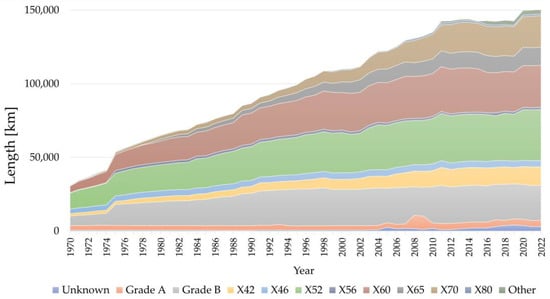
Figure 1.
Total length of pipelines included in the EGIG report by year and material grade. Data from [28].
3. Standards
The most relevant standards and guidelines for the containment and transportation of hydrogen or high-pressure H2/NG mixtures at near-ambient temperatures, developed by various organizations, are as follows:
- ASME VIII Div. 3 “Rules for Construction of Pressure Vessels”, in particular section KD10 “Special Requirements for Vessels in Hydrogen Service” [29].
- ASME B31-12 “Hydrogen Piping and Pipelines” [8].
- ISO 11114 “Gas Cylinders—Compatibility of Cylinder and Valve Materials with Gas Content Part 1 Metallic materials [30], and Part 4 “Test methods for selecting steels resistant to hydrogen embrittlement” [31].
- ANSI/AIAA G-095 “Guide to Safety of Hydrogen and Hydrogen Systems” [32] from the NASA report NASA NSS 1740-16 about the compressed hydrogen employment as fuel in aerospace [33].
- ANSI/CSA CHMC 1-2014 “Test Methods for Evaluating Material Compatibility in Compressed Hydrogen Applications—Metals” [34].
- EIGA IGC Doc 100/03/E “Hydrogen Cylinders and Transport Vessels” [35].
- EIGA IGC Doc 121/14 “Hydrogen Pipeline Systems” [36].
These documents provide guidance on metals compatibility with hydrogen, methods for evaluating such compatibility, judgment criteria, and the interpretation of test results. They specifically address high-pressure operating conditions, under which hydrogen-induced material embrittlement can occur. Regarding compatible materials, the cited standards focus on structural metallic materials used for components such as tanks, pipes, valves, and specialized fittings. When a set of mechanical tests is successfully performed according to a standard it is then considered qualified for hydrogen service according to the specific standard. Conversely, the standards do not consider other metallic materials used as coatings, such as zinc or tin.
The mechanical evaluation approach of HE susceptibility of metal alloys according to ISO 11114-4, ASME VIII Div.3 (+ASME B31-12) and ANSI/CSA CHMC 1 will be analyzed in more detail in this paragraph.
According to these Standards, the HE quantification can be achieved through the evaluation of two kinds of parameters:
- Design parameters to be used when designing a structure that must withstand loads in the presence of pressurized hydrogen, such as pipelines or pressure vessels.
- Qualitative parameters that allow for easier and quicker comparison among different materials to assess their potential suitability for hydrogen service, without providing further information potentially relevant to the component design.
The former includes yield strength (YS), stress intensity factor (KI), and fatigue crack growth rate (da/dN vs. ΔK), while the latter includes elongation at break (El) or reduction in area at fracture (RA) in the tensile test or in general slow strain rate test results, as well as qualitative go/no go disk rupture tests.
3.1. ISO 11114-4
The ISO 11114-4 standard, “Gas Cylinders—Compatibility of Cylinder and Valve Materials with Gas Content—Part 4: Test methods for selecting steels resistant to hydrogen embrittlement” specifically addresses the design of hydrogen service pressure vessels [31], and proposes three equivalent testing methods to assess HE:
- (1)
- Method A: Disk-rupture test.
- (2)
- Method B: Fracture mechanics test, used to determine a threshold value for the stress intensity factor in a gaseous hydrogen environment, KIH.
- (3)
- Method C: Test for determining the resistance of a metallic material to hydrogen assisted fracture.
Method A. The disk-rupture test Figure 2, also standardized in the ASTM F1459 standard [37], measures the rupture pressure of a thin disk of the test metal ruptured in a pure hydrogen atmosphere, comparing it to the pressure obtained under identical conditions using an inert gas, such as helium, as the pressurizing medium. The test is performed on a disk-shaped specimen with a diameter of 58 mm and a thickness of 0.75 mm.
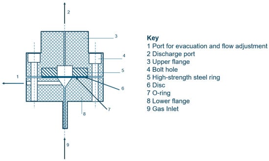
Figure 2.
Schematic representation of the disk rupture test. Adapted from ISO 11114-4 [31].
The test gas is high-purity hydrogen, meeting stringent specifications to ensure reliable results; oxygen and water content in the test gases must always stay below O2 < 1 ppm and H2O < 3 ppm. The low O2 threshold content is required as it can dissociate via electron transfer on the metal surface similarly to hydrogen. However, due to its higher electronegativity, oxygen exhibits a much faster reaction rate. Both hydrogen and oxygen dissociation processes occur simultaneously, competing for the same dissociation sites on the metal surface. Yet, the kinetics and stability of oxygen dissociation make it more efficient, leading to the preferential occupation of dissociation sites on the metal surface. According to Komoda et al. [38] even 0.3 ppm of oxygen is sufficient to observe an inhibitory effect on hydrogen-accelerated fatigue crack growth. This protective effect is independent of gas temperature in the range of −28 °C to 100 °C.
A similar behavior is observed with other gases, such as H2O, CO, CS2, and N2O, which reduce the total number of sites available for hydrogen dissociation and subsequent absorption. Nevertheless, their inhibitory effect is less pronounced compared to oxygen [38,39,40,41,42,43]. This concern is reflected in standards to ensure that the most severe effects are evaluated under equivalent hydrogen pressure conditions during in situ tests.
Several tests at different increase pressure rates need to be performed according to the standard, with the aim of identifying the more severe HE conditions. The results of the tests conducted in hydrogen are then individually compared with the rupture pressure in helium environment, obtained from the interpolation line at the specific pressure ramp rate, using the ratio PrHe/PrH2, where PrHe is the rupture pressure in He and PrH2 the rupture pressure in H2. The maximum value of this ratio obtained from the hydrogen tests provides the material’s susceptibility index to hydrogen. If the ratio is less than or equal to 2, the material is considered suitable for hydrogen service. Nevertheless, the disk rupture test is hardly considerable as mechanical test viable to evaluate HE susceptibility of a steel, but rather an escamotage to decide if it is fit or not for hydrogen service. The reasons are several:
- The sample dimension is 0.75 mm, not representative of the thickness of the real manufactured products.
- The test is performed on a smooth sample and plasticization takes place over the whole sample surface; no engineering parameter is obtained through this test.
- The threshold value 2 for the PrHe/PrH2 ratio is empirical and hold no theoretical background.
Method B is based on fracture mechanics and involves the use of fatigue pre-cracked compact tension (CT) specimens (Figure 3) in accordance with ISO 7539-1 [44] and ISO 7539-6 [45]. Both pre-cracking and testing are conducted in an autoclave at a hydrogen pressure at least equal to the intended operating pressure and at ambient temperature.
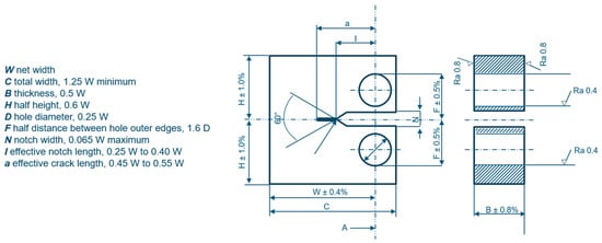
Figure 3.
CT specimen for KIH evaluation through J-integral tests. Adapted from ISO 11114-4 [31].
The required gas purity is the same as in Method A. According to the ISO 11114-4 the CT sample thickness needs to be at least 85% of the actual component thickness. The testing procedure involves applying a stepwise increasing load to the test specimen, with steps of 1 MPa√m starting from an initial value determined according to the standard. The KIH value at which the crack begins to propagate is recorded. The material is considered acceptable if KIH is equal to or greater than the threshold specified in the standard, calculated as 60/950 × UTS MPa√m. The KIH is an engineering parameter of the material and can be used in the design of pressure vessels to calculate the tolerable defect size, differently from the disk rupture test.
The testing conditions and the sample dimension are then highly representative of the real working conditions when a defect in the material is stressed in the presence of hydrogen. Nevertheless, experimental challenges are significant, as the test requires load-control using an electrohydraulic or electromechanical testing machine with an instrumented specimen placed inside an autoclave. This setup introduces complications, including the need to implement airtight passing holes for electrical instrumentation and low-friction feedthroughs for the tension bars.
Testing Method C according to ISO 11114-4 is also based on FM and involves fatigue pre-cracked CT specimens, but under constant deformation. According to the standard, the preloading needs to achieve an applied KI = 1.5 × 60/950 × UTS MPa√m. After the strain application, the samples need to be placed in autoclave for at least 1000 h (42 days) for BCC alloys and 5000 h (209 days) for alloys with face centered cubic structure. At the end of the test, the alloy is considered suitable for hydrogen service if
- The average crack propagation does not surpass 0.25 mm.
- The average crack propagation surpasses 0.25 mm, but the final measured KI is at least equal to 60/950 × UTS MPa√m.
Method C is straightforward to apply, it does not involve the experimental challenges of Method B, and it does not require complex instrumentation. However, the lack of instrumentation means that any information can only be obtained at the conclusion of the test. The test duration is at least 42 days for ferritic or tempered martensitic steels and can extend up to 209 days for austenitic steels, making the testing procedure extremely time-consuming. Furthermore, differently from Method B, it does not provide a specific KI value with engineering relevance for the design process if the crack does not propagate more than 0.25 mm.
3.2. ASME VIII Div 3 (+ASME B31-12)
According to ASME VIII Div. 3 standard, Rules for Construction of Pressure Vessels, in Article KD10, Special Requirements for Vessels in Hydrogen Service [29], materials used for pressure vessels in hydrogen service must be characterized in terms of toughness, KIH, and fatigue resistance, da/dN−ΔK, using fracture mechanics methodologies as detailed in the standard.
Notably, unlike ISO 11114-4, ASME VIII Div.3 recognizes that a pressure vessel is generally a welded structure. Therefore, the values of the relevant parameters must be determined for each material, each specific welding procedure specification, and for the three microstructures of a welded joint: base metal (BM), weld metal (WM), and heat-affected zone (HAZ). The determination of KIH must be performed according to ASTM E1681 [46], and the sample can be subjected to either constant load or constant displacement at an applied KI value established by the user based on a preliminary evaluation using fracture mechanics principles. The tests are conducted in an autoclave, and the hydrogen must meet the following purity requirements: O2 ≤ 1 ppm, CO2 ≤ 1 ppm, CO ≤ 1 ppm, and H2O ≤ 3 ppm. The test durations are also equivalent to the ISO Standard Method C [31]. At the end of the test, the eventual crack propagation is measured and depending on the result there are three possible outcomes:
- The crack does not propagate more than 0.25 mm average, and the test has been conducted at constant load; then KIH = applied KI.
- The crack does not propagate more than 0.25 mm average, and the test has been conducted at constant displacement; then, KIH = ½ applied KI.
- The crack does propagate more than 0.25 mm average; the KIH is measured according to ASTM E1681 [46] par.9.21 and 9.22.
In either case, a KIH value, useful for design purposes is obtained. Furthermore, according to ASME VIII Div 3, the fatigue crack propagation rate da/dN−ΔK also needs to be measured on the material to be used in the same environment of the constant load/strain tests, with a maximum load frequency of 0.1 Hz. The 0.1 Hz threshold is required to allow for hydrogen diffusion and accumulation ahead of the crack tip during the test, to evaluate the maximum HE conditions. Nevertheless, to measure the maximum HE conditions in austenitic steels with face centered cubic structure, the test frequency should be considerably lower, given the low hydrogen diffusion coefficient (hydrogen diffusion coefficient in austenitic steels ∿ 1 × 10⁻¹⁴ m2/s).
Clearly, the two approaches of the ISO and the ASME standard to the HE problem are different: the ISO standard defines a set of equivalent tests that are intended to certify the suitability of the material to hydrogen service without further intent to obtain engineering parameters useful for the product’s design. Nevertheless, if a KIH value is acquired through certification methods B and C proposed by the ISO, it can be used for further design optimization. On the other hand, the ASME focuses on the acquisition of the engineering parameters, to be used during the design process. Furthermore, the ASME standard covers the welding issue, which the ISO does not.
ASME B31-12 [8] does not contain its own criteria but refers to Article KD10 of ASME VIII. It does, however, provide some relevant numerical values: it requires a minimum KIH value of 50 ksi√in (55 MPa√m), while for fatigue it provides a fatigue crack growth rate equation with related parameters that can be applied to any pipeline steel.
3.3. ANSI/CSA CHMC 1
The ANSI/CSA CHMC 1 Standard, Test Methods for Evaluating Material Compatibility in Compressed Hydrogen Applications—Metals [34], outlines various testing methodologies for a broader assessment of the suitability of metallic materials in hydrogen environments. According to the standard, the tests should be conducted in high-purity hydrogen, with the following purity requirements, O2 ≤ 1 ppm, CO2 + CO ≤ 2 ppm, H2O ≤ 3.5 ppm, and N2 ≤ 2 ppm, similarly to the ISO 11114-4 requirements. The test pressure must at least match the maximum allowable working pressure of the component, while the temperature should correspond to the temperature of maximum hydrogen embrittlement. The standard also specifies how to determine the temperature of maximum hydrogen embrittlement.
Chapter 5 of the standard defines the applicable test methodologies, which include the following:
- (1)
- Slow Strain Rate Tensile Test: Conducted on smooth or notched specimens. The strain rate is specified as 10−5 s−1 for smooth specimens and 10−6 s−1 as nominal strain rate measured over a 25.4 mm gauge length across the notch for notched specimens.
- (2)
- Measurement of the Threshold Value for Hydrogen-Assisted Fracture: Conducted under linear elastic fracture mechanics (KIH) or elastic–plastic fracture mechanics (JIH) conditions in a hydrogen environment.
- (3)
- Fatigue Crack Growth Rate Test (da/dN vs. ΔK): Performed at a frequency of 1 Hz, with a load ratio R = 0.1.
- (4)
- Fatigue Life Testing (S-N Curve): Conducted under load-controlled conditions, or under strain-controlled conditions. The load ratio is R = 0.1, and the testing frequency is set at 1 Hz for low-cycle fatigue (number of cycles to failure < 105) or 20 Hz for high-cycle fatigue (number of cycles to failure > 105), followed by statistical analysis of the resulting data.
The material qualification process is described in Chapter 6 of the standard. The diagram presented in Figure 4 outlines the qualification pathway for a material, aiming to minimize the number of tests required to achieve this goal. As the first step, the metal needs to be tested according to the above-described point 1, notched tensile specimens for every metal for exception of Al alloys and austenitic stainless steels, where unnotched tensile specimens can also be employed.
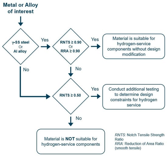
Figure 4.
Qualification process of metals for hydrogen service according to ANSI/CSA CHMC 1. Adapted from ANSI/CSA CHMC 1 [34].
For notched specimens the selection criterion is based on the value of the ratio of the notched tensile strength (RNTS), defined as the ratio between the average fracture loads in hydrogen (NTSH) and in an inert environment (NTSR):
For smooth specimens, the reduction area ratio (RRA) criterion is used instead, defined as the ratio of the reduction area in hydrogen (RAH) and in an inert environment (RAR):
where is the reduction area, A is the final cross section area, and A0 is the initial cross-section area.
For aluminum alloys or austenitic stainless steels, the material is considered suitable for hydrogen service without further design modifications if either RNTS or RRA ≥ 0.90. For all the other materials, as well as for aluminum alloys or austenitic stainless steels that do not meet the above thresholds, the material is deemed unsuitable for hydrogen service unless RNTS ≥ 0.50. If the limit of RNTS ≥ 0.50 is satisfied, the alloy needs to be tested according to points 2, 3, or 4 to obtain engineering parameters for the design of the components, similarly to ASME VIII Div 3 [29].
The ANSI/CSA standard, differently from the ASME, does not cover the welds topic, but contemplates the study of the fatigue behavior of the material in hydrogen environment both through fracture mechanics da/dN vs. ΔK and traditional S-N curves, as well as the JIH parameter for toughness evaluation, allowing for the proper assessment of modern high-yield materials. Also, according to ANSI/CSA CHMC 1, every parameter employed during the component design phase needs to be evaluated also in hydrogen environment (YS, UTS, KIc, JIc, S-N, and da/dN vs. ΔK).
4. Tensile, Fracture Toughness, and Fatigue Tests
While the current standards propose the HE testing methodologies previously outlined, the scientific literature is much more heterogeneous, including environmental conditions, testing parameters and setups well beyond the ones covered by the standards. The current review will narrow its focus on results acquired through tensile tests, fracture toughness tests, and fatigue tests performed in gaseous hydrogen environments.
4.1. Tensile Tests
The tensile test is certainly one of the most widely adopted tests for the evaluation of HE susceptibility of metallic alloys and can be carried out on both smooth and notched specimens with different notch radius.
4.2. Smooth Specimens
In tensile tests performed on smooth specimens, an almost unanimously accepted consideration is that hydrogen has no significant effect on the parameters related to strength: YS and ultimate tensile strength (UTS). Nevertheless, it does have a clear effect on ductility related parameters, El and RA, particularly on the latter. El and RA, however, are not quantitative parameters used in design but can still provide valuable information on the effects of hydrogen on the material.
An example of the experimental result obtained in a tensile test with a smooth specimen is given in Figure 5 [47]. As shown, the stress–strain curves from hydrogen-exposed tests deviate from the reference curve in air only after the maximum load is reached, at the onset of necking, where stress localization occurs and fracture initiation and propagation begin. This behavior is consistent with the role of hydrogen in reducing the cohesive energy of metals, as proposed by several established theories. Among the most widely recognized are the hydrogen-enhanced decohesion, hydrogen-enhanced localized plasticity, and adsorption-induced dislocation emission mechanisms, which have been thoroughly examined by Lynch in his comprehensive review of hydrogen embrittlement phenomena and mechanisms [3].
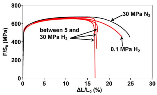
Figure 5.
Tensile curves on smooth API 5L X80 steel specimen in hydrogen atmosphere at different pressures [47] (Reprinted with permission from Ref. [47]. 2025, Elsevier).
The values of the tensile properties acquired by San Marchi and Somerday, Duncan et al., Hejazi et al., and Nanninga et al. [13,48,49,50,51] on various pipeline steels and other carbon steels for pressure vessels tested in gaseous hydrogen pressures ranging between 5.5 and 10 MPa are summarized in Figure 6. As it appears from Figure 6, the YS hydrogen embrittlement index ranges between −9% and +10% are not statistically significant, similarly to the UTS hydrogen embrittlement index, ranging between −3% and +6% with mean value equal to 1.3%. The embrittlement index XEI in percentage for a specified parameter X is defined as
where
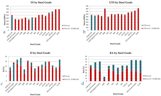
Figure 6.
YS (a), UTS (b), El (c), and RA (d) in inert and high-pressure hydrogen environments, various pipeline steel grades, ordered by increasing nominal yield strength. Smooth tensile specimens. Data from [13,48,49,50,51].
- ▪
- parameter acquired in inert environment;
- ▪
- parameter acquired in hydrogen environment.
In contrast, the ductility related parameters, El and RA, undergo a marked degradation, as highlighted in Figure 6c,d. RA is the most sensitive parameter to gaseous hydrogen, with a marked decrease ranging from 14% to 61%, with average value of 40%, while El reduction is still consistent, but less marked, with a maximum reduction of 37% and an average value of 18%. Furthermore, in a couple instances, no El reduction was recorded in presence of hydrogen, while for the case of A516 steel, the material showed higher elongation in hydrogen rather than in air (Figure 6c).
Coherent results were obtained across all the steel grades tested by the authors, ranging from an A106 Gr B to more performing X70 and X100 pipeline steels, without clear correlation between steel grades and susceptibility to hydrogen.
Similarly, Boukortt et al. [52] state that there is no significant correlation in the change in yield strength and ultimate tensile strength for any grade of material in presence of hydrogen (Figure 7), while claiming that elongation decreases along with the increase in YS, although the latter statement seems rather forced based on the data shown in Figure 8, where the trend line is drawn rather arbitrarily with a low correlation coefficient.
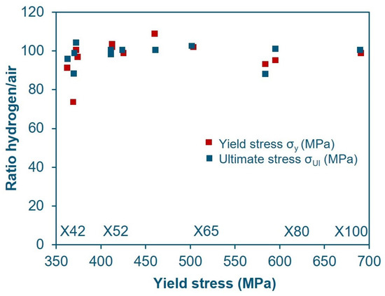
Figure 7.
YS in-H2/YS in-air ratio and UTS in-H2/UTS in-air ratio for various pipeline steels as a function of material yield strength in air [52] (Adapted with permission from Ref. [52]. 2025, Elsevier).
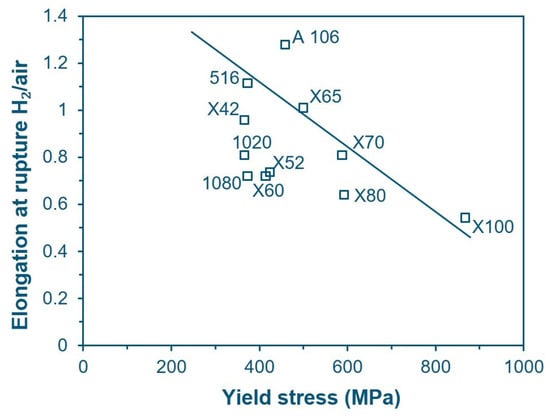
Figure 8.
El in-H2/El in-air ratio for various pipeline steels as a function of yield strength in air [52] (Adapted with permission from Ref. [52]. 2025, Elsevier).
Nanninga et al. [13,50] also state that susceptibility to HE increases with material grade, as through their study on X52, X65, and X100, they obtained an El in-H2/El in-air ratio of 0.78, 0.72, and 0.50, respectively, clearly highlighting a trend. Nevertheless, Stalheim et al. [53], testing four materials (X60 Sour Service, X70 and two X80), concluded that the material grade has no specific effect on embrittlement, while the microstructure is more relevant: the best behavior was recorded with an equiaxial ferrite microstructure mixed with 10% acicular ferrite, while the worst one was observed for ferritic/pearlitic microstructures.
4.2.1. Effect of Hydrogen Partial Pressure
One of the test’s most significant parameters that influences the outcome of the tensile tests is the hydrogen partial pressure. This parameter is related to the hydrogen concentration inside the material when in equilibrium with the surrounding gaseous environment, under conditions representative of long-term service exposure. In fact, the concentration of hydrogen in a metal in equilibrium with an atmosphere of hydrogen gas is given by Sieverts’ law:
where CH is the concentration of hydrogen in a metal when equilibrium conditions of the whole system have been reached and thus when the concentration within the material is uniform throughout the thickness. Under non-equilibrium conditions, CH is the concentration of hydrogen absorbed in a few atomic layers immediately below the physical surface of the metal. fH2 is the fugacity of hydrogen in the gaseous atmosphere, and K depends on temperature according to the following relationship:
K0 is a constant and is the heat of solution and depend on the metal, R is the universal gas constant, and T the absolute temperature [54].
The hydrogen fugacity, is defined as
where b is a constant equal to 1.584 × 10⁻⁵ m3mol−1 [55].
In a gas mixture containing hydrogen and other components, such as a hydrogen/natural gas blend, the hydrogen partial pressure (pH2) is defined as the product of its molar fraction in the mixture and the absolute pressure. Strictly speaking, the hydrogen fugacity should be considered instead of the partial pressure; however, for pressures up to approximately 10 MPa, the two values are nearly equivalent [56].
As already discussed, strength-related parameters are mostly unaffected by hydrogen presence in smooth specimens’ tensile tests, independent of the hydrogen pressure in the range of values involved in the gas transport and storage [47]. Nevertheless, ductility rapidly decreases with the increase of pH2, until it reaches a plateau in the cases presented for pH2 values above 5–10 MPa. A collection of values of ductility loss (El reduction) in presence of variable pressure for several pipeline steel alloys is shown in Figure 9 [15,47,49,51,57].
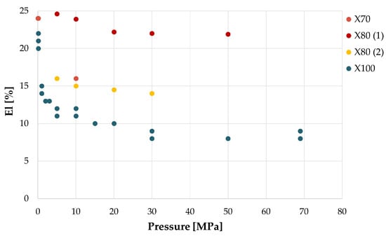
Figure 9.
El as function of hydrogen pressure for four pipeline steels. From the data of [15,47,49,51,57].
Meng et al. [15] performed tensile tests on X80 steel specimens in mixtures of natural gas and hydrogen at total pressure of 12 MPa, at different hydrogen percentages, confirming that YS and UTS are essentially unaffected, while El and RA, on the other hand, undergo an increasing reduction with hydrogen pressure, up to 17.5% and 15.9%, respectively, at pH2 = 2.4 MPa, while from pH2 = 2.4 MPa to pH2 = 6 MPa, both parameters decrease only marginally, respectively, to 18.6% and 16.8%.
Moro et al. [47] obtain a similar trend of ductility as a function of hydrogen pressure in tensile tests on smooth X80 steel specimens. Nevertheless, the two ductility parameters, El and RA, do not always display consistent behaviors with each other, e.g., Nguyen et al. [57] tested an X70 steel in air, in helium at 10 MPa, in NG + 1% H2 mixture at 10 MPa total pressure, and in the same mixture after 720 h of specimen conditioning to the test environment. While RA is the same in air, in helium, and in the presence of the NG + 1% H2 mixture, it decreases by 51% in pure hydrogen. El decreases by 9% in helium, by 2.5–4% in the presence of the NG + 1% H2 mixture, and by 33% in pure hydrogen. Apparently then, under these experimental conditions, considering only the parameter El, one could conclude that helium has greater embrittling effects than 0.1 MPa of hydrogen. Bertini et al. [58] on an X52 steel obtained reductions similar to Meng’s for El and RA, not greater than 15 % on an X52-grade steel pre-charged with hydrogen at 5, 10, and 15 MPa.
4.2.2. Effect of the Strain Rate
The influence of strain rate on hydrogen embrittlement can be understood by considering the role of hydrogen diffusion in relation to the material’s microstructure. Once absorbed into the metal lattice, hydrogen atoms interact with microstructural heterogeneities such as vacancies, dislocations, grain boundaries, inclusions, precipitates, voids, and secondary phases, which act as reversible or irreversible trapping sites. The density and nature of these traps, together with the crystal structure of the metal phases (BCC for most pipeline alloys), determine the effective hydrogen diffusion coefficient (DH), which controls hydrogen mobility, and therefore its ability to accumulate at critical locations, such as the crack tip and regions under isostatic stresses. API 5L [25] and API 5CT [59] specifications cover a wide range of steel grades, from low-strength carbon–manganese steels (e.g., Grade A, B, X42, X52, H40, J55) with coarse-grained ferritic–pearlitic microstructures to high-strength micro- and low-alloyed steels (e.g., X80, X100, T95, P110, Q125) with ferritic–bainitic or bainitic–martensitic microstructures. The former, often produced through annealing to relieve thermal stresses, provoking grain growth, have relatively few trapping sites and thus higher DH values, typically in the range of 1 × 10⁻¹¹ to 5 × 10⁻¹⁰ m2/s. The latter, produced through grain refinement and precipitation strengthening, presents a much higher density of traps (grain boundaries, dislocations, and precipitates), which lead in consequence to significantly lower DH values [60,61,62,63]. The severity of hydrogen embrittlement is strongly influenced by the time available for hydrogen to diffuse into and redistribute within the plastic zone ahead of the crack tip. Lower strain rates provide hydrogen with more time to migrate to these critical regions, increasing embrittlement susceptibility. However, once the strain rate falls below a threshold determined by DH, hydrogen redistribution can keep pace with crack tip advancement, and further reductions in strain rate no longer affect crack growth.
Tensile tests in the presence of hydrogen are usually conducted according to ASTM G129 “Standard Practice for Slow Strain Rate Testing to Evaluate the Susceptibility of Metallic Materials to Environmentally Assisted Cracking” [64], originally developed for the study of Stress Corrosion Cracking phenomena, but it is well suited to study hydrogen embrittlement conditions where the phenomenon is controlled by the penetration and diffusion rate of hydrogen atoms into the metal, which are inherently slow processes. Therefore, in an extremely slow test, the solid-state diffusion phenomena are able to keep the pace and influence the dislocation generation and movement responsible for the plasticization of the materials and ultimately the fracture processes.
As can be seen from the study of Moro et al. [47] (Figure 10), the fracture elongation of the material decreases as the strain rate decreases over a wide range from 5.5 × 10⁻¹ to 5.5 × 10⁻⁷ s−1 but the most significant effects occur from velocities lower than about 10−4 s−1, while the RA is about constant in the 5 × 10⁻³ s−1 to 5.5 × 10⁻⁷ s−1 velocity range with a decrease of 63–68% compared to the test in an inert environment (nitrogen).
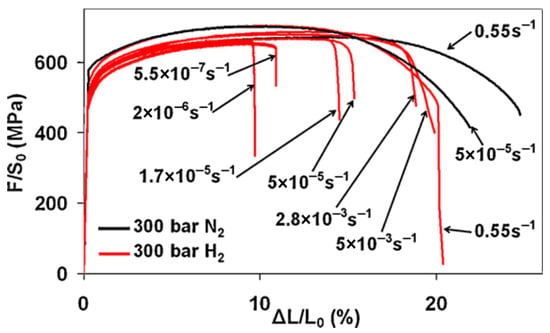
Figure 10.
Tensile curves on X80 steel at different deformation rates [47] (Reprinted with permission from Ref. [47]. 2025, Elsevier).
4.3. Notched Specimens
Tensile tests performed on notched specimens on the other hand yield substantially different results, as the fracture mechanism is influenced by the stress intensity ahead of the notch. Differently from the tensile tests on smooth specimens previously described, the notched tensile strength (NTS) is affected by hydrogen.
Song et al. [65] subjected X70 steel notched specimens with very severe notching, i.e., notch bottom radius 0.083 mm, to tensile tests in helium and in pure hydrogen at 10 MPa applying different moving crosshead speeds (Figure 11). The hydrogen embrittling effect reaches a maximum for a moving crosshead speed of 1 × 10⁻³–5 × 10⁻⁴ mm/s, the NTSloss parameter being defined as
where
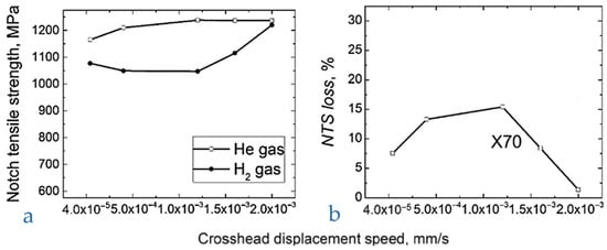
Figure 11.
Tensile tests on notched specimens at different speeds of crosshead, X70 steel. (a) NTS, (b) NTS loss. Adapted from [65] (Adapted with permission from Ref. [65]. 2025, Elsevier).
- -
- NTSHe is the NTS measured in He environment.
- -
- NTSH is the NTS measured in hydrogen environment.
The measured NTSloss ranged between 13–15%. The ANSI/CSA CHMC 1 standard [34] requires a value of RNTS of at least 90% to successfully qualify a metal for hydrogen service, being
Therefore, in the most critical range, RNTS is worth about 85–87%, lower than the minimum acceptable value for the mentioned standard; therefore, in the tested conditions, the X70 should be considered unacceptable for hydrogen service.
Nguyen et al. [57,66,67] conducted tests on X70 steel, studying both the base material and the weld metal of a welded joint, using notched specimens with a notch tip radius of 0.083 mm. However, the applied strain rate of 2·× 10−2 mm/s did not comply with the requirements of the previously mentioned ANSI/CSA standard. Testing was performed in a pure hydrogen atmosphere at 10 MPa, yielding RNTS values of 0.97 relative to air and 0.92 relative to helium. These results highlight the critical influence of test parameter selection on the measured outcomes.
The tests of these authors, while criticizable for the aspects already mentioned, highlight another relevant parameter for the outcome of tests on notched specimens, namely, the geometry of the notch, and more precisely, the radius of the notch tip; using radii of 0.083, 1.5, and 6 mm, they obtain the results displayed in Figure 11, where the stress concentration factor Kt is a parameter inversely related to the notch radius, r, equal to 1.26, 1.82, and 5.59 for r equal to 6, 1.5, and 0.083 mm, respectively.
The effect of Kt on the final RRA measurement is significant, with values decreasing to approximately 40–50% in the case of severe notching as shown in Figure 12. In contrast, due to the reasons previously discussed, the reduction in NTS remains modest, consistently below 5%, except for the weld metal, where it reaches 8–9% only under conditions of the most severe notching. Moreover, the NTSloss does not exhibit a significant dependence on the notch radius.
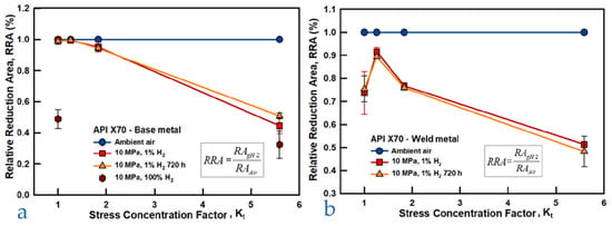
Figure 12.
RA comparison of different specimen types under three environmental conditions for (a) base metal and (b) weld metal [66] (Reprinted with permission from Ref. [66]. 2025, Elsevier).
4.4. Fracture Toughness Tests
Before reviewing the information available in the literature about fracture toughness of pipeline steels measured according to fracture mechanics methods, it is appropriate to make some considerations about this type of testing, which can be performed on different specimen geometries and different modes.
Fracture toughness is a highly relevant parameter for assessing the embrittling effect of hydrogen, as it reflects a macroscopic material behavior strongly influenced by the reduction in cohesive strength and by possible modifications in fracture morphology induced by hydrogen, intrinsic consequences of hydrogen embrittlement mechanisms [3]. Evaluating fracture toughness in a hydrogen environment therefore provides valuable insight of the embrittlement severity under specific conditions, while also indirectly providing information on the influence of hydrogen on fracture behavior, similarly to fracture toughness testing used to characterize the temperature-dependent ductile–brittle transition in metals. Furthermore, fracture mechanics tests are able to take into account the influence of the presence of cracks, not present in the previously described tests.
The most comprehensive and reliable test standard for evaluating a critical value of K or J is ASTM E1820 [68], which requires specimens of geometry defined by the standard to be stressed in increasing tensile or bending stress until crack propagation occurs; from the load–displacement curve measured on the load axis, test data are obtained to be entered into the formulas for computing the critical value of the parameter being measured. If the test is conducted by keeping the specimen in a hydrogen environment at the desired pressure and temperature, a critical value of KIH or JIH specific to the material under test under the environmental test conditions will be obtained.
The KIH and JIH parameters are critical not only for the design of newly constructed pipelines intended for hydrogen transport, but also for assessing the feasibility of hydrogen blending in existing infrastructure. Pipeline design always incorporates a damage tolerance approach, and the ASME B31.12 [8] standard currently specifies a minimum KIc value of 55 MPa√m, recognizing that defects are inevitably present in such large-scale structures and represent the weakest link in the system. This requirement becomes even more significant when repurposing existing pipelines for H2/NG blends, since a reduced KIH in a hydrogen-rich environment must be compensated by a downgrade in allowable service conditions to maintain the safety margins originally designed for natural gas transport.
The ASME B31.12 standard allows for the use of test methods described in ASTM E1681 [46], which is specifically designed for evaluating stress corrosion cracking. These methods enable the determination of a critical toughness value through either constant load or constant displacement testing.
In constant load tests, multiple specimens are subjected to increasing load within a predefined range, maintained constant throughout the duration of exposure in an environment simulating service conditions. If a crack begins to propagate, the applied stress intensity factor increases progressively until the specimen fails. The lowest initial KI value at which crack propagation does not occur is taken as the critical stress intensity factor for hydrogen-assisted cracking, denoted as KIH.
In constant displacement tests, by contrast, the specimen is initially loaded to a deformation level corresponding to an applied KI value exceeding the expected KIH. Provided the testing procedures are correctly followed, the crack begins to propagate, causing a gradual reduction in the applied KI. Crack arrest occurs when the applied stress intensity factor equals the critical value, i.e., when the applied KI = KIH.
The first testing methodology mentioned here, i.e., the one based on ASTM E1820, is the most complex and expensive, requires the use of a sophisticated testing machine and instrumentation [68], but provides the most reliable results. In contrast, constant deformation tests, which are the easiest to implement, are the least reliable.
Another important point to keep in mind is the exact definition of the test parameter being considered; in fact, the value of K or J can be calculated at different points of the experimental test curve, obtaining critical parameters with different meanings; in particular, K can be calculated by the linear elastic criteria as KQ, as given in Annex A5 of ASTM E1820, or it can be derived from JIc by the following formula:
where
- -
- JIc is the critical value of J that also includes the plastic strain energy and the energy required for the initial tearing of the specimen from the fatigue crack.
- -
- E is Young’s modulus.
- -
- ν is Poisson’s modulus.
KJIc is thus an elastoplastic parameter that includes a contribution due to the energy absorbed by the material during the test up to a predefined crack propagation value or up to maximum load. Note also that there is a square root relationship between K and J so the calculated values of parameter reduction in the presence of hydrogen relative to air may differ significantly.
Finally, it should be pointed out again that ASME Standard B31.12 designates 50 ksi√in or 55 MPa√m as the minimum acceptable limit value of KIH for steels adoptable in hydrogen transport pipelines without, however, indicating on what basis this value was adopted. By placing E and ν in Equation (9) equal to 210 GPa and 0.3, respectively, the acceptability limit of toughness according to ASME B31.12 measured with the J-integral parameter takes the value JIc = 13.1 N/mm. However, the ASME B31.12 is currently under revision by the committee, and a newly released version could possibly feature different acceptability limits.
The document DVGW Project SyWeSt H2—Investigation of Steel Materials for Gas Pipelines and Plants for Assessment of their Suitability with Hydrogen—Final Report Jan. 2023 [69] deserves special consideration when discussing about fracture toughness tests in hydrogen. In anticipation of the energy scenario described above, the DVGW (Deutsche Verein des Gas und Wasserfaches) conducted an extensive investigation on a consistent number of materials currently used in Germany and Europe for the transport of natural gas and measured the critical KI value and the fatigue crack growth rate in hydrogen at 10 MPa at room temperature for each of them. The suitability to hydrogen service was judged according to the criteria of the ASME B31.12 [8] standard mentioned above.
The critical KI value was obtained by means of J-integral tests according to ASTM E1820 on CT specimens and from the measured JIc value, a KJIc value was calculated using Equation (9).
Twenty-six pipeline materials were considered (plus five valve materials) covering production years from 1930 to 2022, with nominal YS ranging between 207 MPa to 550 MPa and actual YS ranging between 294 MPa to 584 MPa. The studied steels have highly variable microstructures, covering the evolutionary history of pipeline steels, which was briefly mentioned earlier.
For each steel, the BM was always tested, and sometimes the longitudinal or spiral weld of the pipe production or the circumferential field joint weld. For the welds, mainly the WM was tested and only in few cases also the HAZ. The results of KJIc tests on BM are shown in Figure 13. The test scheme is presented in Table 1.
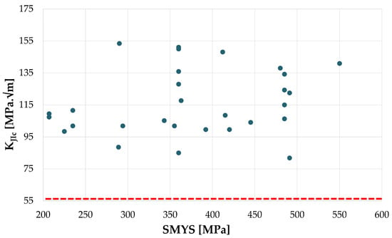
Figure 13.
Pipeline steels BM, KJIc vs. SMYS. Dashed red line equivalent to 55 MPa√m. From the data of Project SyWeSt H2 [69].

Table 1.
Outline of the tested materials and conditions. Adapted from Project SyWeSt H2 [69].
All KJIc values in hydrogen at 10 MPa measured on BM are above 80 MPa√m according to the study, while no specific correlation is observed with the minimum guaranteed YS or the actual YS, nor with the year of production. Nevertheless, the reference value of KJIc in inert environment was not measured for most of the materials; therefore, no considerations can be made on the embrittlement index from the data acquired in the study.
Furthermore, in the same study [69], two materials—two St35 steels from different years of production, 1930 and 1937, and an L485 (X70) steel from 2017—were tested both in air and at different hydrogen partial pressures. The two materials, despite being extremely different in terms of microstructure and mechanical properties, gave very congruent results, as displayed in Figure 14a. The presence of hydrogen even at low partial pressure, 0.02 MPa, causes a significant reduction in the KJIc parameter, which decreases more modestly up to about 2 MPa, but at this point the phenomenon seems to saturate, and an increase in partial pressure up to 10 MPa has negligible effect.
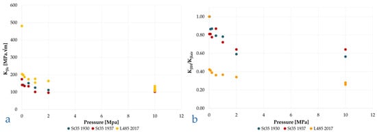
Figure 14.
(a) St35 and L485 steels, KJIc vs. hydrogen partial pressure. (b) St35 and L485 steels, KJIH/KJIair vs. hydrogen partial pressure. From the data of [69].
In terms of absolute values, the difference between the two materials in the presence of hydrogen is modest, whereas in relative terms, the change in KI compared to the test in air is far more significant for material L485, equivalent to API 5L X70 (Figure 14b).
Similar results and trends were obtained by other authors [48,69,70,71,72,73] and are collected in a Figure 15a,b to properly appreciate their coherency among each other.
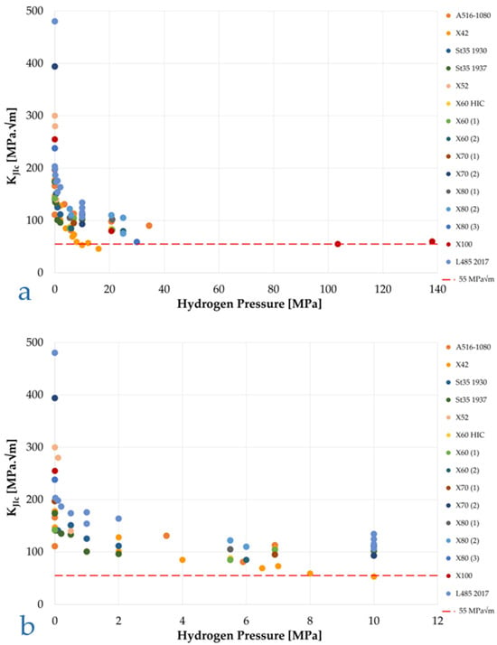
Figure 15.
Collection of KJIc acquired by several authors through in situ high-pressure hydrogen fracture toughness tests. Various pipeline steel grades: (a) 0–140 MPa pressure range; (b) zoom on 0–12 MPa range. From the data of [48,69,70,71,72,73].
San Marchi and Somerday [48], summarizing the results obtained by various authors on vessel and pipeline steels, found out that the value of KIH is markedly pressure-dependent, as previously observed for other mechanical parameters, yet for the materials and hydrogen pressure conditions it is always higher than the minimum limit required by ASME B31-12, with the only exception of an API 5L X42 steel at pressures above 10 MPa. Higher-grade steels have higher KIH values, although no precise correlation can be identified between the steel grade and its toughness in hydrogen.
In a successive study, San Marchi et al. [70] report the results of KJIc tests in hydrogen at different partial pressures for different API 5L pipe steels from grade X52 to grade X80. According to the conducted tests, the authors conclude that “Fracture resistance in gaseous hydrogen nominally scales with strength properties”. The use of the term “nominally” makes the sentence ambiguous; comparing the KJIc obtained by San Marchi et al. with those obtained by DVGW, we must conclude that these data are within the scatter band of this kind of test and confirm the non-dependence of KJH on yield strength. Furthermore, the measured KJIc are perfectly aligned with the DVGW results [69], as well as with the ones summarized in Figure 15a. Furthermore, the KJIc reduction trend as function of hydrogen pressure displays a clear analogy with the one already highlighted for elongation in Figure 9. The authors conclude that the hydrogen embrittlement effect already occurs from very low values of hydrogen concentration.
Briottet et al. [74] on an X80 steel observed a KJIc variation from 220 MPa√m to 58.8 MPa√m at 30 MPa of hydrogen pressure, with a reduction of 73.3%. These authors also performed autoclave tests with constant-strain wedge-opening-load (WOL) specimens loaded at K values between 39 MPa√m and 111 MPa√m without detecting any crack advancement after 1000 h of hydrogen exposure at the same pressure.
In contrast, Keller et al. [73] in tests on X100 steel WOL specimens at different hydrogen pressures obtained the results in Figure 16. These results confirm what was said in the introduction to this chapter about the poor reliability of constant displacement tests for measuring hydrogen gas embrittlement.
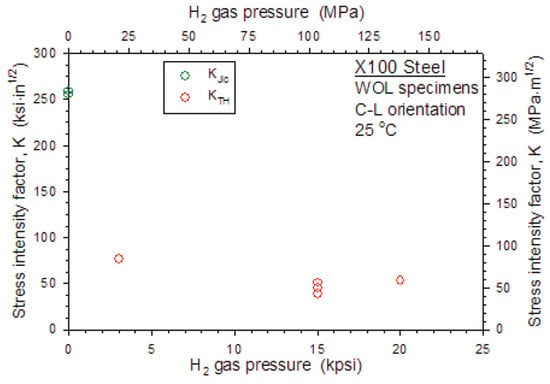
Figure 16.
Critical K vs. hydrogen pressure on X100. WOL specimens. Reprint from [73].
As mentioned above regarding tensile tests, even in toughness tests according to ASTM E1820, the speed at which the test is performed has a relevant effect on the result.
Alvarez et al. [20] performed J-integral tests on two structural steels: a ferritic–pearlitic S355 steel with nominal YS = 390 MPa, and a martensitic tempered H8 steel with YS = 790 MPa, pre-charged with hydrogen (19.5 MPa, 450 °C, 21 h), on single-edge notch bending, at three different moving crosshead translation speeds, 10−1, 10−2, and 10−3 mm/min, as shown in Figure 17. The results prove that for both materials, as the crosshead speed decreases from 10−1 mm/min to 10−3 mm/min, the measured KIH decreases. This effect appears to be limited for the lower yield strength S355 steel, displaying a ferritic–pearlitic microstructure and a hydrogen diffusion coefficient DH = 13 × 10−10 m2/s at room temperature, as a crosshead speed of 10−1 mm/min already gives a significant KIH reduction of 36% with respect to the test performed without hydrogen, which further decreases only slightly along with the test speed (43% KIH reduction with a crosshead speed of 10−3 mm/min). Nevertheless, the KIH reduction is strongly influenced by strain rate in the higher yield H8 steel, with a tempered martensitic microstructure and a DH = 0.85 13 × 10−10 m2/s at room temperature, initially decreasing by 24% at 10−1 mm/min, up to a consistent 87% reduction at 10−3 mm/min.
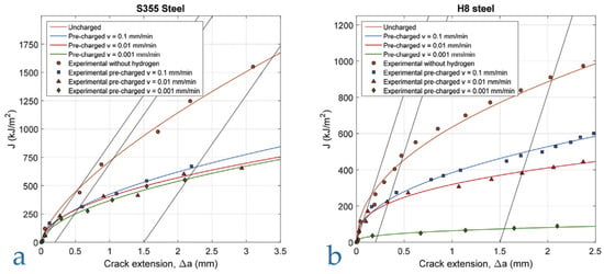
Figure 17.
Fracture toughness vs. crack extension of hydrogen pre-charged samples at various strain rates (v): (a) S355 steel; (b) H8 steel [20] (Reprinted with permission from Ref. [20]. 2025, Elsevier).
Alvarez et al. suggests that the effect of strain rate is strongly dependent on the hydrogen diffusion coefficient (DH) of the material under investigation. A sufficiently low strain rate promotes hydrogen accumulation ahead of the crack tip, thereby amplifying the embrittlement effect under given environmental conditions. Consequently, a threshold strain rate can be identified, below which further strain rate reductions no longer influence the test outcome, as hydrogen redistribution within the lattice can keep pace with the movement of the crack tip and the associated plastic zone.
Comparable results were obtained by Nykyforchyn et al. [75] in J-integral tests on hydrogen-pre-charged API X52 steel SENB specimens, tested at displacement rates of 0.5, 0.05, and 0.005 mm/min. The observed trend was consistent with that reported by Alvarez et al. for S355 steel, showing a modest yet systematic increase in embrittlement with decreasing strain rate.
4.5. Fracture Mechanics Fatigue Tests
It is universally accepted that a pressurized hydrogen gas environment reduces the fatigue life of pipeline steels and accelerates the crack growth rate relative to air under the same mechanical stress conditions. The ASME B31.12 [8] and ASME VIII Div. 3 [29] provide for the calculation of the tolerability of a defect in a pipeline or pressure vessel by including the possibility of fatigue growth of an initial defect. This growth must be calculated using fracture mechanics methods starting from the spectrum of load variation expected in service. Various institutions have therefore conducted fatigue tests on pipeline steels, publishing the results, which constitute a large body of shared data on which to construct reference fatigue curves, “master curves”, to be introduced into the above standards.
In an inert environment, when the crack propagation is controlled exclusively by the variation in mechanical load, the fatigue growth law in carbon or low-alloy steels often takes the form da/dN = A(ΔK) in a relatively wide range of values of ΔK; this relationship is known as Paris’ law. In the presence of hydrogen or corrosive environments, the function da/dN-ΔK takes a more articulated course, which can be schematized in one of the three possible types in Figure 18 [76]; region 2 of the fatigue curve in an inert environment is the one that can be described by Paris’ law.
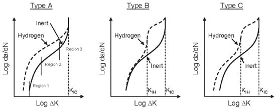
Figure 18.
Different types of possible curves of HA-FCG (Hydrogen-Assisted Fatigue Crack Growth). Reprint from [76].
The analysis of the literature data is complex, since this phenomenon is affected by various parameters, the most important of which are the material and its microstructure, particularly in welded joints in which the base material, the weld metal, and the heat-affected zone behave differently; the partial pressure of hydrogen; the ratio R = Kmin/Kmax per cycle; and the frequency. In all cases, the test temperature is the ambient temperature.
A first reference from which to start in this analysis is Amaro et al. [77], who summarize and elaborate on a considerable number of results obtained at NIST [14,78,79,80,81,82] on X52, X70, and X100 steels from different years of production (“new”, “vintage”), tested in a hydrogen atmosphere at different partial pressures and at room temperature, Figure 19.
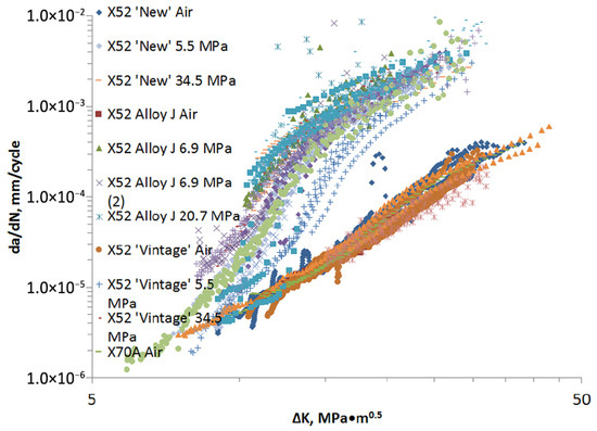
Figure 19.
HA-FCG data collected at NIST on X52, X70, and X100 steels with a SMYS between 358 MPa and 689 MPa at hydrogen pressures between 1.7 MPa and 34.5 MPa. All data generated at a frequency of 1 Hz and R = 0.5 [77] (Reprinted with permission from Ref. [77]. 2025, ASME).
The first observation is that the fatigue curves in air for all materials considered in this study follow Paris’ law in the range 10–40 MPa√m and are contained in a single, rather narrow band. In hydrogen, on the other hand, the curves da/dN-ΔK can be divided into three regions as shown in Figure 20.
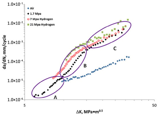
Figure 20.
Typical HA-FCG results of API X100 steel delineated into three regions: A, B, and C. All data generated at a frequency of 1 Hz and R = 0.5 [77] (Reprinted with permission from Ref. [77]. 2025, ASME).
There is a first region (A) in the low range of ΔK (ΔK < 8 MPa√m) where the material behaves as in air; a second (B), for 8 MPa√m < ΔK < 15 MPa√m, of very rapid growth in the fatigue rate; and a third (C), for ΔK > 15 MPa√m, of still linear trend with a lower slope, close to that in air, but with velocities almost two orders of magnitude greater than this (between 30 and 100 in this case). The transition points between the different regions depend on the material and the partial pressure of hydrogen. In regions B and C, an increase in the partial pressure of hydrogen corresponds to an increase in the rate of fatigue crack growth, but this effect is limited.
Starting from these data, researchers of the National Institute of Standards and Technology propose a mathematical model based on a superposition of effects principle. Subsequently, at the request of the ASME B31.12 committee, the equation was simplified for easier engineering applicability and thus assumed the final form currently found in ASME B31.12, Equation (10), and Table 2.

Table 2.
Fatigue crack growth rate da/dN-ΔK and related parameters according ASME B31.12 [8] (Reprinted with permission from Ref. [8]. 2025, American Society of Mechanical Engineers (ASME)).
4.5.1. Effect of Hydrogen Partial Pressure
In the fatigue crack growth rate tests carried out at National Institute of Standards and Technology, the frequency, f = 1 Hz, and the R-ratio were kept constant (R = 0.5), while the hydrogen partial pressure was varied, which, however, showed a modest effect on this type of steel as mentioned above. Somerday et al. [83] present fatigue data on an X60 steel at f = 1 Hz and R = 0.1 at hydrogen pressures between 5.5 and 103 MPa and state: “Fatigue crack growth in gaseous hydrogen does not depend on pressure for high ΔK.” A similar result is given by Meng et al. [15] in NG/H2 mixtures with content of the latter gas between 5 and 50 percent.
On the contrary, Nanninga et al. [76] report data from Holbrook et al. on an X42 steel tested in fatigue at 0.1 Hz and R = 0.25, at ΔK = 22 MPa√m, showing a hydrogen pressure dependence with a power law with exponent 0.36.
Xu [84] shows instead that, for f = 1 Hz, R = 0,1, and ΔK = 22 MPa√m, the effect of hydrogen reaches saturation already for pressures of 5–10 MPa in three materials very different in terms of yield strength and microstructure, and according to the study, it should also be noted that, with ΔK being equal, the fatigue crack growth rate (FCGR) decreases as the material grade increases.
Slifka et al. [82] report fatigue data on the four pipeline steels (X52 and X70), and for all materials and all tested frequencies, the rate of hydrogen fatigue propagation increases with the partial pressure of the gas.
Chen et al. [85] develop a mathematical model for predicting hydrogen fatigue data by also considering a dependency of FCGR on hydrogen partial pressure and verify it on the same data presented by Slifka et al. [82] for X52 “Vintage” steel, concluding that “The model was able to correctly capture the dependency of HA-FCGR on hydrogen pressure with reasonable accuracy.”
As can be seen from the results presented, there is no consensus on the effect of hydrogen pressure on FCGR and this is probably also due to the combined effect of the different test parameters and particularly of PH2, f, and R.
4.5.2. Effect of the Frequency
Suresh and Ritchie [78] schematize the effect of frequency and R-ratio on the FCGR curve in the way shown in Figure 21.
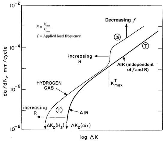
Figure 21.
Schematic diagram of the effect of f and R on FCGR in hydrogen: (IG) intergranular fracture; (T) transgranular fracture. Reprint from [78].
Concerning the effect of frequency in Xu [84] and Nibur and Somerday [86], we also find some general considerations derived from the examination of the results of other authors. First of all, it is generally accepted that the FCGR increases as the frequency decreases; however, this effect is relevant up to a value of f about equal to 0.1–1 Hz for values of ΔK up to about 20 MPa√m [86]. On the contrary, Walter and Chandler [87], on a low-grade carbon-manganese steel, SA-105 Grade II, detect a constant increase in FCGR with power law up to f = 3.3 × 10⁻⁴ Hz.
The data reported by Dadfarnia et al. [88] on an X70 steel in a frequency range of 1 to 10−2 Hz confirms the above about the low influence of frequency for values below 1 Hz. The results of Slifka et al. [82] also show that there is no longer test frequency dependence for values below 1 Hz.
4.5.3. Effect of R
The parameter R in the diagram of Figure 21 shifts the threshold values of the onset of fatigue phenomena, ΔK0, and of the transition from region A to region B, KTmax. The experimental data supporting this theory are very few and seem to indicate that the effect only manifests itself at values of R greater than 0.5 [48].
The parameter R is not taken into account in the ASME engineering formula for calculating the growth of a hydrogen fatigue crack and its effect is implicitly considered when assuming the upper bound of the experimental data.
On the other hand, San Marchi et al. [89] developed a two-segment straight-line model that considers the R-factor for ferritic steels for high-pressure vessels and also applied it in [70] to API 5L pipeline steels. The two proposed equations are
Equation (11) applies for the lower values of ΔK and includes a factor that depends on the hydrogen fugacity, f, raise to the power ½, while Equation (12) applies in the range of higher values of ΔK, where fatigue no longer depends on hydrogen pressure.
5. Discussion and Concluding Remarks
The experimental evidence collected from the reviewed literature and standards highlights that the susceptibility of pipeline steels to hydrogen embrittlement HE is best understood taking into account for both mechanical and environmental factors. Across the presented testing methodologies, hydrogen primarily degrades ductility and fracture-toughness related properties, while strength parameters remain largely unaffected within the pressure ranges relevant to hydrogen transport applications. This behavior reflects the fact that hydrogen mostly affects crack initiation and propagation mechanisms rather than bulk elastic–plastic properties.
5.1. Trends in Hydrogen Pressure Effects
Tensile (RA, El) and fracture (KIH, KJIc) mechanics already consistently show steep degradation with hydrogen pressures as low as 0.02–0.1 MPa, usually followed by a plateau for pressures above ~5–10 MPa. This rapid onset and following plateau behavior suggests that, beyond a threshold fugacity, hydrogen lattice and trapping sites ahead of the crack tip or more generally in the plastic deformation region become saturated, and further pressure increases do not significantly alter crack tip fracture morphology or decohesion kinetics. Furthermore, the analogies in degradation profiles for RA and KIH, which can be clearly seen comparing Figure 9 and Figure 15, point to a common underlying embrittlement mechanism for tensile and fracture J-integral tests. Therefore, according to the authors, both tensile and J-integral testing methodologies appear to provide relevant information for the quantification of hydrogen embrittlement. Nevertheless, despite being more complex and expansive with respect to their tensile counterpart, J-integral tests provide a KIH value in a specific hydrogen environment, an extremely relevant parameter for a proper pipeline design [8].
By contrast, the influence of hydrogen pressure on FCGR is far less consistent. Some studies report a clear positive correlation [82,84], others find negligible dependence [15,83], and in several instances, pressure effects appear to be significant only in intermediate ΔK regimes (Region B of Figure 20). This scatter may be explained by differences in R-ratio, frequency, and microstructure, underscoring the need for standardizing these parameters when comparing fatigue data.
5.2. Strain Rate and Frequency as Rate-Controlling Parameters
Strain rate in monotonic loading and frequency in cyclic loading act as kinetic controls on hydrogen redistribution. For tensile and fracture toughness tests, susceptibility increases markedly when strain rate falls below ~10−4 s−1, with smooth-specimen elongation and RA reaching a minimum, and KIH dropping toward alloy-specific lower bounds. This trend aligns with diffusion-controlled HE behavior, where lower rates allow sufficient time for hydrogen to redistribute and accumulate at crack tips and plasticization regions. The sensitivity to strain rate is more pronounced in higher-strength, finer-microstructure steels due to their lower DH. On the other hand, the effect of strain rate appears to saturate already when higher strain rates are applied, coherently with the higher DH associated to coarse grained microstructures.
In fatigue, a similar threshold emerges: lowering the loading frequency below ~1 Hz (and in some cases down to ~0.1 Hz) increases FCGR until saturation. The effect is most evident in low or intermediate ΔK regimes, where crack tip hydrogen transport can keep pace with cyclic loading, amplifying the embrittlement process.
5.3. Influence of Steel Grade
Literature results indicate that yield strength alone is a poor predictor of HE susceptibility, as highlighted by Figure 6, Figure 8 and Figure 13. Over larger statistic samples, a trend may be observed, yet no generalization of the concept can be lightly made. For example, some X70 and X100 grades display similar RA and KIH losses despite large strength differences. Furthermore, the overall variety of testing setups and specifically tailored solutions that researchers may employ to solve issues related to in situ high-pressure hydrogen testing further complicates the possibility of a univocal interpretation.
Microstructural features, rather than only yield strength, may be more indicated to predict more reliably expected susceptibility to hydrogen [53].
5.4. Standards and Research
A key contrast emerges between the “go/no-go” philosophy of ISO 11114-4 and the design-oriented focus of ASME VIII Div. 3, B31.12, and ANSI/CSA CHMC 1. Literature data show that most pipeline steels exceed the ASME’s KIH threshold (55 MPa√m) even at pressures up to 30 MPa, yet significant ductility and toughness losses occur below this limit, as the original KJIc of pipeline steels is often well above 200 MPa√m (Figure 15). This raises the question of whether the current threshold-based acceptance criteria sufficiently capture the functional performance degradation relevant to service life, particularly under fatigue loading where standardization is weakest.
The lack of unified consideration for parameters such as notch geometry (tensile), R-ratio (fatigue), and realistic weld microstructures in ISO protocols also limits the predictive capability of standard tests for actual service conditions.
5.5. Implications and Knowledge Gaps
From an engineering standpoint, the observed convergence of plateau pressures (~5–10 MPa) and critical strain/frequency thresholds across test types could guide the design of accelerated yet representative HE qualification protocols. However, major uncertainties remain:
- The mechanistic origin of scatter in FCGR–pressure correlations, particularly the relation between R-ratio and ΔK.
- Quantitative correlation between laboratory-measured degradation indices (RAloss, KIH reduction) and in-service defect tolerance.
- Standardized approaches for including weldments and heat-affected zones in HE qualification, as ASME requires but ISO omits.
- Harmonization of strain rate/frequency regimes to capture diffusion-controlled embrittlement without unrealistic test durations.
Author Contributions
Conceptualization, L.P. and G.R.; methodology, L.P. and G.R.; formal analysis, L.P., G.R., A.C. and F.B.; investigation L.P., G.R. and A.C.; resources G.R., L.P. and F.B.; data curation, A.C. and L.P.; writing—original draft preparation, G.R. and L.P.; writing—review and editing, F.B., M.O. and A.C.; visualization, A.C. and L.P.; supervision, F.B. and M.O.; project administration, F.B. and M.O.; funding acquisition, F.B. and M.O. All authors have read and agreed to the published version of the manuscript.
Funding
The present activity was funded by the Hydrogen Joint Research Partnership (https://www.fondazionepolitecnico.it/progetti/hydrogen-jrp/, accessed on 1 July 2025), promoted by Politecnico di Milano and Fondazione Politecnico di Milano.
Data Availability Statement
All the data presented in this review are acquired from the scientific literature reported in the References Section.
Acknowledgments
The authors would like to thank Politecnico di Milano and Fondazione Politecnico di Milano for the support provided during the research.
Conflicts of Interest
The authors declare no conflicts of interest.
Abbreviations
| Acronym | Full Form |
| API | American Petroleum Institute |
| ASME | American Society of Mechanical Engineers |
| ASTM | American Society for Testing and Materials |
| BM | Base Metal |
| CT | Compact Tension |
| DH | Hydrogen Diffusion Coefficient |
| EGIG | European Gas Pipeline Incident data Group |
| El | Elongation at break |
| EIGA | European Industrial Gases Association |
| FCGR | Fatigue Crack Growth Rate |
| HA-FCG | Hydrogen-Assisted Fatigue Crack Growth |
| HE | Hydrogen Embrittlement |
| JIC | J-integral-based critical fracture toughness |
| JIH | J-integral-based critical fracture toughness in a hydrogen environment |
| KI | Stress Intensity Factor |
| KIC | Critical Stress Intensity Factor |
| KIH | Critical stress intensity factor in a hydrogen environment |
| KJIc | KIC calculated from JIC |
| Kt | Stress Concentration Factor |
| NG | Natural Gas |
| NTS | Notched Tensile Strength |
| NTSH | Notched Tensile Strength in Hydrogen |
| NTSR | Notched Tensile Strength in Reference/Inert Environment |
| NTSloss | Loss in Notched Tensile Strength due to Hydrogen |
| pH2 | Partial Pressure of Hydrogen |
| PrH2 | Disk rupture pressure in H2 |
| PrHe | Disk rupture pressure in He |
| RA | Reduction in Area at Fracture |
| RAR | Reduction in Area in Reference/Inert Environment |
| RAH | Reduction in Area in Hydrogen Environment |
| RNTS | Ratio of NTSH to NTSR |
| RRA | Reduction in Area Ratio |
| R | Load ratio in fatigue testing |
| SMYS | Specified Minimum Yield Strength |
| UTS | Ultimate Tensile Strength |
| WM | Weld Metal |
| WOL | Wedge-Opening Load |
| YS | Yield Strength |
References
- Crolet, J.L. Analysis of the various processes downstream cathodic hydrogen charging, I: Diffusion, laboratory permeation and measurement of hydrogen content and diffusion coefficient. Mater. Tech. 2016, 104, 205. [Google Scholar] [CrossRef]
- Pisarev, A.A. Hydrogen adsorption on the surface of metals. In Gaseous Hydrogen Embrittlement of Materials in Energy Technologies; Elsevier: Amsterdam, The Netherlands, 2012; pp. 3–26. [Google Scholar] [CrossRef]
- Lynch, S.P. Hydrogen embrittlement (HE) phenomena and mechanisms. Stress Corros. Crack. Theory Pract. 2011, 30, 90–130. [Google Scholar] [CrossRef]
- Gangloff, R.P. Hydrogen-assisted Cracking. Compr. Struct. Integr. Nine Vol. Set 2003, 1–9, 31–101. [Google Scholar] [CrossRef]
- Sergeev, N.N.; Sergeev, A.N.; Kutepov, S.N.; Kolmakov, A.G.; Gvozdev, A.E. Mechanism of the Hydrogen Cracking of Metals and Alloys, Part II (Review). Inorg. Mater. Appl. Res. 2019, 10, 32–41. [Google Scholar] [CrossRef]
- Chen, Y.-S.; Huang, C.; Liu, P.-Y.; Yen, H.-W.; Niu, R.; Burr, P.; Moore, K.L.; Martínez-Pañeda, E.; Atrens, A.; Cairney, J.M. Hydrogen trapping and embrittlement in metals—A review. Int. J. Hydrogen Energy 2025, 136, 789–821. [Google Scholar] [CrossRef]
- Parliament, E. Directive (EU) 2018/2001 of the European Parliament and of the Council of 11 December 2018 on the promotion of the use of energy from renewable sources (recast). Off. J. Eur. Union 2018, 2018, 82–209. [Google Scholar]
- ASME B31.12-2023; Hydrogen Piping and Pipelines. The American Society of Mechanical Engineers: New York, NY, USA, 2023.
- Hayden, L.; Douglas, S. Hydrogen piping and pipeline code design rules and their interaction with pipeline material concerns, issues and research. In Proceedings of the ASME 2009 Pressure Vessels and Piping Division Conference, Prague, Czech Republic, 26–30 July 2009; pp. 1–7. [Google Scholar]
- Duprez, L.; Leunis, E.; Güng, Ö.E.; Claessens, S. Hydrogen embrittlement of high strength, low alloy (HSLA) steels and their welds. In Gaseous Hydrogen Embrittlement of Materials in Energy Technologies; Woodhead Publishing: Sawston, UK, 2012. [Google Scholar] [CrossRef]
- Johnson, W. On some remarkable Changes produced in Iron and Steel by the action of Hydrogen and Acids. R. Soc. 1875, 11, 168–179. [Google Scholar] [CrossRef]
- Bhadeshia, H.K.D.H. Prevention of hydrogen embrittlement in steels. ISIJ Int. 2016, 56, 24–36. [Google Scholar] [CrossRef]
- Nanninga, N.; Levy, Y.; Drexler, E.; Condon, R.; Stevenson, A.; Slifka, A. Tensile Behavior of Pipeline Steels in High Pressure Gaseous Hydrogen Environments. pp. 1–33. Available online: https://tsapps.nist.gov/publication/get_pdf.cfm?pub_id=907912 (accessed on 24 August 2025).
- Amaro, R.L.; Drexler, E.S.; Slifka, A.J. Fatigue crack growth modeling of pipeline steels in high pressure gaseous hydrogen. Int. J. Fatigue 2014, 62, 249–257. [Google Scholar] [CrossRef]
- Meng, B.; Gu, C.; Zhang, L.; Zhou, C.; Li, X.; Zhao, Y.; Zheng, J.; Chen, X.; Han, Y. Hydrogen effects on X80 pipeline steel in high-pressure natural gas/hydrogen mixtures. Int. J. Hydrogen Energy 2017, 42, 7404–7412. [Google Scholar] [CrossRef]
- Valentini, R.; Bacchi, L.; Biagini, F.; Mastroianni, M. Application of laboratory and on field techniques to determine the risk of hydrogen embrittlement in gaseous hydrogen and relative mixtures transport and storage. Matériaux Tech. 2023, 111, 202. [Google Scholar] [CrossRef]
- Venezuela, J.; Gray, E.; Liu, Q.; Zhou, Q.; Tapia-Bastidas, C.; Zhang, M.; Atrens, A. Equivalent hydrogen fugacity during electrochemical charging of some martensitic advanced high-strength steels. Corros. Sci. 2017, 127, 45–58. [Google Scholar] [CrossRef]
- Koren, E.; Hagen, C.M.H.; Wang, D.; Lu, X.; Johnsen, R.; Yamabe, J. Experimental comparison of gaseous and electrochemical hydrogen charging in X65 pipeline steel using the permeation technique. Corros. Sci. 2023, 215, 111025. [Google Scholar] [CrossRef]
- Rahimi, S.; Verbeken, K.; Depover, T.; Proverbio, E. Hydrogen embrittlement of pipeline steels under gaseous and electrochemical charging: A comparative review on tensile properties. Eng. Fail. Anal. 2025, 167, 108956. [Google Scholar] [CrossRef]
- Álvarez, G.; Peral, L.B.; Rodríguez, C.; García, T.E.; Belzunce, F.J. Hydrogen embrittlement of structural steels: Effect of the displacement rate on the fracture toughness of high-pressure hydrogen pre-charged samples. Int. J. Hydrogen Energy 2019, 44, 15634–15643. [Google Scholar] [CrossRef]
- Nguyen, T.T.; Park, J.; Nahm, S.H.; Tak, N.; Baek, U.B. Ductility and fatigue properties of low nickel content type 316L austenitic stainless steel after gaseous thermal pre-charging with hydrogen. Int. J. Hydrogen Energy 2019, 44, 28031–28043. [Google Scholar] [CrossRef]
- Colombo, C.; Fumagalli, G.; Bolzoni, F.; Gobbi, G.; Vergani, L. Fatigue behavior of hydrogen pre-charged low alloy Cr-Mo steel. Int. J. Fatigue 2015, 83, 2–9. [Google Scholar] [CrossRef]
- Paterlini, L.; Vergani, L.; Ormellese, M.; Curia, A.; Re, G.; Bolzoni, F. Hydrogen Embrittlement of a T95 Low-Alloy Steel Charged by Electrochemical Method. Materials 2025, 18, 1047. [Google Scholar] [CrossRef]
- Li, X.; Zhang, J.; Cui, Y.; Djukic, M.B.; Feng, H.; Wang, Y. Review of the hydrogen embrittlement and interactions between hydrogen and microstructural interfaces in metallic alloys: Grain boundary, twin boundary, and nano-precipitate. Int. J. Hydrogen Energy 2024, 72, 74–109. [Google Scholar] [CrossRef]
- API 5L-2018; Specification for Line Pipe. American Petroleum Institute: New York, NY, USA, 2018.
- ISO 3183; Petroleum and Natural Gas Industries—Steel Pipe for Pipeline Transportation Systems. International Organization for Standardization: Geneva, Switzerland, 2019.
- Stalheim, D.; Barnes, K.; McCutcheon, D. Alloy Designs for High Strength Oil and Gas Transmission Linepipe Steels. In International Symposium Microalloyed Steels for the Oil and Gas Industry; TMS: Pittsburgh, PA, USA, 2007; pp. 73–108. [Google Scholar]
- European Gas Pipeline Incident Data Group. 12th Report of EGIG, GAS PIPELINE INCIDENTS. 2023. Available online: https://www.EGIG.eu (accessed on 23 August 2025).
- ASME VIII Div. 3; Rules for Construction of Pressure Vessels, Article KD10 “Special Requirements for Vessels in Hydrogen Service”. The American Society of Mechanical Engineers: New York, NY, USA, 2023.
- ISO 11114-2023; Gas Cylinders—Compatibility of Cylinder and Valve Materials with Gas Content—Part 1 Metallic Materials. International Organization for Standardization: Geneva, Switzerland, 2023.
- ISO 11114-2017; Gas Cylinders—Compatibility of Cylinder and Valve Materials with Gas Content—Part 4 “Test Methods for Selecting Steels Resistant to Hydrogen Embrittlement”. International Organization for Standardization: Geneva, Switzerland, 2017.
- ANSI/AIAA G-095A; Guide to “Safety of Hydrogen and Hydrogen Systems”. American National Standard Institute: Washington, DC, USA, 2017.
- NASA NSS 1740-16; Safety Standard for Hydrogen and Hydrogen Systems. National Aeronautics and Space Administration: Washington, DC, USA, 1997.
- ANSI/CSA CHMC 1; Test Methods for Evaluating Material Compatibility in Compressed Hydrogen Applications—Metals. American National Standards Institute: Washington, DC, USA, 2014.
- EIGA IGC Doc 100/03/E; Hydrogen Cylinders and Transport Vessels. European Industrial Gases Association: Brussels, Belgium, 2003.
- EIGA IGC Doc 121/14; Hydrogen Pipeline Systems. European Industrial Gases Association: Brussels, Belgium, 2014. Available online: https://www.eiga.eu (accessed on 19 August 2025).
- ASTM F1459-06; Test Method for Determination of the Susceptibility of Metallic Materials to Hydrogen Gas Embrittlement (HGE). American Society for Testing and Materials, ASTM International: West Conshohocken, PA, USA, 2006. [CrossRef]
- Komoda, R.; Kubota, M.; Staykov, A.; Ginet, P.; Barbier, F.; Furtado, J. Inhibitory effect of oxygen on hydrogen-induced fracture of A333 pipe steel. Fatigue Fract. Eng. Mater. Struct. 2019, 42, 1387–1401. [Google Scholar] [CrossRef]
- Michler, T.; Boitsov, I.E.; Malkov, I.L.; Yukhimchuk, A.A.; Naumann, J. Assessing the effect of low oxygen concentrations in gaseous hydrogen embrittlement of DIN 1.4301 and 1.1200 steels at high gas pressures. Corros. Sci. 2012, 65, 169–177. [Google Scholar] [CrossRef]
- Zhang, R.; Yuan, C.; Liu, C.; Wang, C.; Xu, X.; Zhang, J.; Li, Y. Effects of natural gas impurities on hydrogen embrittlement susceptibility and hydrogen permeation of X52 pipeline steel. Eng. Fail. Anal. 2024, 159, 108111. [Google Scholar] [CrossRef]
- Louthan, M.R.; Swanson, R.E. Material Defects, Gas Purity and Hydrogen Embrittlement. Int. J. Hydrogen Energy 1985, 10, 551–554. [Google Scholar] [CrossRef]
- Deimel, P.; Leonhard, H.; Sattler, E. Characterization of the Influence of High-Pressure Hydrogen Gas on the Ductility of the Steel 15 MnNi 6 3. Int. J. Hydroqen Energy 1993, 18, 313–318. [Google Scholar] [CrossRef]
- Zhou, C.; Zhou, H.; Zhang, L. The Impact of Impurity Gases on the Hydrogen Embrittlement Behavior of Pipeline Steel in High-Pressure H2 Environments. Materials 2024, 17, 2157. [Google Scholar] [CrossRef] [PubMed]
- ISO 7539-1; Corrosion of Metals and Alloys—Stress Corrosion Testing—Parti 1: General Guidance on Testing Procedures. International Organization for Standardization: Geneva, Switzerland, 2012.
- ISO 7539-6; Corrosion of Metals and Alloys—Stress Corrosion Testing—Part 6: Preparation and Use of Precracked Specimens for Tests Under Constant Load or Constant Displacement. International Organization for Standardization: Geneva, Switzerland, 2018. Available online: https://standards.iteh.ai/catalog/standards/sist/81596795-66e4-438a-9c03- (accessed on 19 August 2025).
- ASTM E1681-03; Standard Test Method for Determining Threshold Stress Intensity Factor for Environment-Assisted Cracking of Metallic Material. American Society for Testing and Materials: West Conshohocken, PA, USA, 2020. [CrossRef]
- Moro, I.; Briottet, L.; Lemoine, P.; Andrieu, E.; Blanc, C.; Odemer, G. Hydrogen embrittlement susceptibility of a high strength steel X80. Mater. Sci. Eng. A 2010, 527, 7252–7260. [Google Scholar] [CrossRef]
- Marchi, C.S.; Somerday, B.P. Technical Reference for Hydrogen Compatibility of Materials; Sandia National Laboratories (SNL): Albuquerque, NM, USA, 2012. [Google Scholar]
- Hejazi, D.; Calka, A.; Dunne, D.; Pereloma, E. Materials Science and Technology Effect of gaseous hydrogen charging on the tensile properties of standard and medium Mn X70 pipeline steels Effect of gaseous hydrogen charging on the tensile properties of standard and medium Mn X70 pipeline steels. Mater. Sci. Technol. 2016, 32, 675–683. [Google Scholar] [CrossRef]
- Nanninga, N.E.; Levy, Y.S.; Drexler, E.S.; Condon, R.T.; Stevenson, A.E.; Slifka, A.J. Comparison of hydrogen embrittlement in three pipeline steels in high pressure gaseous hydrogen environments. Corros. Sci. 2012, 59, 1–9. [Google Scholar] [CrossRef]
- Duncan, A.; Lam, P.S.; Adams, T. Tensile testing of carbon steel in high pressure hydrogen. Am. Soc. Mech. Eng. Press. Vessel. Pip. Div. (Publ.) PVP 2008, 6, 519–525. [Google Scholar] [CrossRef]
- Boukortt, H.; Amara, M.; Meliani, M.H.; Bouledroua, O.; Muthanna, B.; Suleiman, R.; Sorour, A.; Pluvinage, G. Hydrogen embrittlement effect on the structural integrity of API 5L X52 steel pipeline. Int. J. Hydrogen Energy 2018, 43, 19615–19624. [Google Scholar] [CrossRef]
- Stalheim, D.; Bogges, T.; Marchi, C.S.; Somerday, B.; Boggess, T.; Jansto, S. Microstructure and Mechanical Property Performance of Commercial Grade Api. In Proceedings of the 8th International Pipeline Conference, Calgary, AB, Canada, 27 September–1 October 2010; pp. 1–9. [Google Scholar]
- Trautmann, A.; Mori, G.; Oberndorfer, M.; Bauer, S.; Holzer, C.; Dittmann, C. Hydrogen uptake and embrittlement of carbon steels in various environments. Materials 2020, 13, 3604. [Google Scholar] [CrossRef]
- Li, Q.; Ghadiani, H.; Jalilvand, V.; Alam, T.; Farhat, Z.; Islam, M.A. Hydrogen Impact: A Review on Diffusibility, Embrittlement Mechanisms, and Characterization. Materials 2024, 17, 965. [Google Scholar] [CrossRef]
- Venezuela, J.; Tapia-Bastidas, C.; Zhou, Q.; Depover, T.; Verbeken, K.; Gray, E.; Liu, Q.; Liu, Q.; Zhang, M.; Atrens, A. Determination of the equivalent hydrogen fugacity during electrochemical charging of 3.5NiCrMoV steel. Corros. Sci. 2018, 132, 90–106. [Google Scholar] [CrossRef]
- Nguyen, T.T.; Park, J.; Kim, W.S.; Nahm, S.H.; Beak, U.B. Effect of low partial hydrogen in a mixture with methane on the mechanical properties of X70 pipeline steel. Int. J. Hydrogen Energy 2020, 45, 2368–2381. [Google Scholar] [CrossRef]
- Bertini, L.; De Sanctis, M.; Lovicu, G.; Santus, C.; Valentini, R. Metodologia per lo studio dell’infragilimento da idrogeno in lamiere sottili di acciai duttili. In Proceedings of the I Congresso Nazionale del Coordinamento della Meccanica Italiana, Palermo, PA, Italy, 20–22 June 2010; pp. 1–10. [Google Scholar]
- API Spec 5CT; Specification for Casing and Tubing. American Petroleum Institute: Singapore, 2019.
- Chen, J.; Wu, J. Hydrogen Diffusion Through Copper-Plated AISI 4140 STEELS. Corros. Sci. 1992, 33, 657–666. [Google Scholar] [CrossRef]
- Souza, R.C.; Pereira, L.R.; Starling, L.M.; Pereira, J.N.; Simões, T.A.; Gomes, J.A.C.P.; Bueno, A.H.S. Effect of Microstructure on Hydrogen Diffusion in Weld and API X52 Pipeline Steel Base Metals under Cathodic Protection. Int. J. Corros. 2017, 2017, 1–14. [Google Scholar] [CrossRef]
- Mohtadi-Bonab, M.A.; Masoumi, M. Different aspects of hydrogen diffusion behavior in pipeline steel. J. Mater. Res. Technol. 2023, 24, 4762–4783. [Google Scholar] [CrossRef]
- Parvathavarthini, N.; Saroja, S.; Dayal, R.K.; Khatak, H.S. Studies on hydrogen permeability of 2.25% Cr-1% Mo ferritic steel: Correlation with microstructure. J. Nucl. Mater. 2001, 288, 187–196. [Google Scholar] [CrossRef]
- ASTM G129–21; Practice for Slow Strain Rate Testing to Evaluate the Susceptibility of Metallic Materials to Environmentally Assisted Cracking. American Society for Testing and Materials, ASTM International: West Conshohocken, PA, USA, 2021. [CrossRef]
- Song, E.J.; Baek, S.W.; Nahm, S.H.; Baek, U.B. Notched-tensile properties under high-pressure gaseous hydrogen: Comparison of pipeline steel X70 and austenitic stainless type 304L, 316L steels. Int. J. Hydrogen Energy 2017, 42, 8075–8082. [Google Scholar] [CrossRef]
- Nguyen, T.T.; Heo, H.M.; Park, J.; Nahm, S.H.; Beak, U.B. Stress concentration affecting hydrogen-assisted crack in API X70 pipeline base and weld steel under hydrogen/natural gas mixture. Eng. Fail. Anal. 2021, 122, 105242. [Google Scholar] [CrossRef]
- Nguyen, T.T.; Tak, N.; Park, J.; Nahm, S.H.; Beak, U.B. Hydrogen embrittlement susceptibility of X70 pipeline steel weld under a low partial hydrogen environment. Int. J. Hydrogen Energy 2020, 45, 23739–23753. [Google Scholar] [CrossRef]
- ASTM E1820-20; Test Method for Measurement of Fracture Toughness. American Society for Testing and Materials: West Conshohocken, PA, USA, 2020.
- Steiner, M.; Marewski, U.; Silcher, H. DVGW Project SyWeSt H2—Investigation of Steel Materials for Gas Pipelines and Plants for Assessment of their Sustainability with Hydrogen; DeutscherVerein des Gas und Wasserfaches: Bonn, Germany, 2023. [Google Scholar]
- Marchi, C.S.; Shrestha, R.; Ronevich, J. Hydrogen compatibility of structural materials in natural gas networks. In Proceedings of the International Conference on Hydrogen Safety, Edinburgh, Scotland, 21–24 September 2021. [Google Scholar] [CrossRef]
- Briottet, L.; Batisse, R.; Dinechin, G.; Langlois, P.; Thiers, L. Recommendations on X80 steel for the design of hydrogen gas transmission pipelines. Int. J. Hydrogen Energy 2012, 37, 9423–9430. [Google Scholar] [CrossRef]
- Martin, M.; Connolly, M.; Buck, Z.; Bradley, P.; Lauria, D. Evaluating a natural gas pipeline steel for blended hydrogen service. J. Nat. Gas Sci. Eng. 2022, 101, 104529. [Google Scholar] [CrossRef]
- Keller, J.; Somerday, B.; Marchi, C.S. Annual Progress Report “Enabling Hydrogen Embrittlement Modeling of Structural Steels”. Sandia National Laboratories: Livermore, CA, USA, 2008; pp. 412–414. Available online: https://www.hydrogen.energy.gov/docs/hydrogenprogramlibraries/pdfs/progress08/iii_11_keller.pdf?sfvrsn=eac30fe9_1 (accessed on 23 August 2025).
- Briottet, L.; Moro, I.; Lemoine, P. Quantifying the hydrogen embrittlement of pipeline steels for safety considerations. Int. J. Hydrogen Energy 2012, 37, 17616–17623. [Google Scholar] [CrossRef]
- Nykyforchyn, H.; Tsyrulnyk, O.; Venhryniuk, O.; Zvirko, O. Techniques for investigation of hydrogen influence on fracture toughness and embrittlement of pipeline steels. Procedia Struct. Integr. 2024, 59, 125–130. [Google Scholar] [CrossRef]
- Nanninga, N.; Slifka, A.; Levy, Y.; White, C. A review of fatigue crack growth for pipeline steels exposed to hydrogen. J. Res. Natl. Inst. Stand. Technol. 2010, 115, 437–452. [Google Scholar] [CrossRef]
- Amaro, R.L.; White, R.M.; Looney, C.P.; Drexler, E.S.; Slifka, A.J. Development of a Model for Hydrogen-Assisted Fatigue Crack Growth of Pipeline Steel1. J. Press. Vessel. Technol. 2018, 140, 021403. [Google Scholar] [CrossRef]
- Suresh, S.; Ritchie, R.O. Mechanistic dissimilarities between environmentally-influenced fatigue-crack propagation at near-threshold and higher growth rates in lower-strength steels. Met. Sci. 1982, 16, 529–538. [Google Scholar] [CrossRef]
- Amaro, R.L.; Rustagi, N.; Drexler, E.S.; Slifka, A.J. Sensitivity Analysis of Fatigue Crack Growth Model for API Steels in Gaseous Hydrogen. J. Res. Natl. Inst. Stand. Technol. 2014, 119, 6–14. [Google Scholar] [CrossRef]
- Amaro, R.L.; Rustagi, N.; Findley, K.O.; Drexler, E.S.; Slifka, A.J. Modeling the fatigue crack growth of X100 pipeline steel in gaseous hydrogen. Int. J. Fatigue 2014, 59, 262–271. [Google Scholar] [CrossRef]
- Slifka, A.J.; Drexler, E.S.; Nanninga, N.E.; Levy, Y.S.; McColskey, J.D.; Amaro, R.L.; Stevenson, A.E. Fatigue crack growth of two pipeline steels in a pressurized hydrogen environment. Corros. Sci. 2014, 78, 313–321. [Google Scholar] [CrossRef]
- Slifka, A.J.; Drexler, E.S.; Amaro, R.L.; Hayden, L.E.; Stalheim, D.G.; Lauria, D.S.; Hrabe, N.W. Fatigue Measurement of Pipeline Steels for the Application of Transporting Gaseous Hydrogen. J. Press. Vessel. Technol. 2018, 140, 011407. [Google Scholar] [CrossRef]
- Marchi, C.S.; Somerday, B.P.; Nibur, K.A.; Stalheim, D.G.; Boggess, T.; Jansto, S. Fracture and Fatigue of Commercial Grade API Pipeline Steels in Gaseous Hydrogen. In Proceedings of the ASME 2010 Pressure Vessels and Piping Conference: Volume 6, Parts A and B, ASMEDC, Bellevue, WA, USA, 18–22 July 2010; pp. 939–948. [Google Scholar] [CrossRef]
- Xu, K. Hydrogen embrittlement of carbon steels and their welds. In Gaseous Hydrogen Embrittlement of Materials in Energy Technologies; Elsevier: Amsterdam, The Netherlands, 2012; pp. 526–561. [Google Scholar] [CrossRef]
- Chen, Y.; Wang, Y.Y. Performance Evaluation of High-Strength Steel Pipelines for High-Pressure Gaseous Hydrogen Transport; United States. Office of Pipeline Safety: Washington, DC, USA, 2013. [Google Scholar]
- Nibur, K.A.; Somerday, B.P. Fracture and fatigue test methods in hydrogen gas. In Gaseous Hydrogen Embrittlement of Materials in Energy Technologies; Elsevier: Amsterdam, The Netherlands, 2012; pp. 195–236. [Google Scholar] [CrossRef]
- Walter, R.J.; Chandler, W.T. Crack Growth in Asme SA-105S Grade II Steel in Hydrogen at Ambient Temperature. Rockwell International Corp.: Cenoga Park, CA, USA, 1975. Available online: https://ntrs.nasa.gov/api/citations/19750011340/downloads/19750011340.pdf (accessed on 24 August 2025).
- Dadfarnia, M.; Sofronis, P.; Brouwer, J.; Sosa, S. Assessment of resistance to fatigue crack growth of natural gas line pipe steels carrying gas mixed with hydrogen. Int. J. Hydrogen Energy 2019, 44, 10808–10822. [Google Scholar] [CrossRef]
- Marchi, C.S.; Ronevich, J.; Bortot, P.; Wada, Y.; Felbaum, J.; Rana, M. Technical Basis for Master Curve for Fatigue Crack Growth of Ferritic Steels in High-Pressure Gaseous Hydrogen in ASME Section VIII-3 Code. In Volume 1: Codes and Standards, Proceedings of the ASME 2019 Pressure Vessels & Piping Conference, San Antonio, TX, USA, 14–19 July 2019; American Society of Mechanical Engineers: New York, NY, USA, 2019. [Google Scholar] [CrossRef]
Disclaimer/Publisher’s Note: The statements, opinions and data contained in all publications are solely those of the individual author(s) and contributor(s) and not of MDPI and/or the editor(s). MDPI and/or the editor(s) disclaim responsibility for any injury to people or property resulting from any ideas, methods, instructions or products referred to in the content. |
© 2025 by the authors. Licensee MDPI, Basel, Switzerland. This article is an open access article distributed under the terms and conditions of the Creative Commons Attribution (CC BY) license (https://creativecommons.org/licenses/by/4.0/).