Abstract
The paper aims to investigate the failure modes induced by the Rockwell indentation test on Diamond-Like Carbon (DLC)-based and AlCrN coatings deposited on rolled and additively manufactured Ti6Al4V substrates with different surface finishes and subjected to two distinct post-process heat treatments, and the possible correlations with scratch tests. At the magnification required to capture the entire Rockwell imprint, the adhesion class of the investigated DLC-based and AlCrN coatings could be incorrectly classified as HF1. However, higher-magnification observations revealed numerous radial cracks and non-uniformly distributed small delamination areas, changing the adhesion class to HF3. Additionally, roughness values higher than 1 μm hid the presence of radial cracks, which aligned parallel to the deep dales and high peaks of the roughness profile, as investigated by SEM. Likewise, in the scratch test, the rough surface also made the smallest cracks, formed at the critical load LC1, undetectable. The critical loads for spallation of the coating in the scratch test (LC2, LC3) did not show significant correlation with the number of radial cracks formed during Rockwell indentations. Consequently, a quick Rockwell indentation cannot predict the scratch test results. Finally, both DLC-based and the AlCrN coatings exhibited good adhesion to Ti6Al4V substrates, regardless of the microstructure and surface finish of the titanium substrates. SEM-FIB observations revealed that the cracks formed during Rockwell indentation and scratch tests were deflected longitudinally within the underlying layers of the DLC-based coating and in the bottom part of the AlCrN coating, where the N concentration was higher.
1. Introduction
The Ti6Al4V alloy is the most studied and widely used lightweight titanium alloy due to its high specific strength, corrosion resistance, and biocompatibility. Consequently, it finds extensive use in various industrial applications such as prostheses, implants, and components for high-performance engines in motor race and aerospace vehicles [1,2]. Generally, Ti6Al4V components are produced through conventional manufacturing (CM) processes, including forging, casting and rolling, and through subsequent post-processes conferring the final shape. In contrast, Powder-based Additive Manufacturing processes, such as Laser Powder Bed Fusion (LPBF), enable the direct production of near-net-shape metallic components from a CAD model by adding metal powders layer by layer [3]. The most significant advantage of LPBF is its capability to produce complex-shaped components with high yield and ultimate tensile strength faster than the CM processes. However, the presence of unprocessed powder particles in contact with the external surface of the manufactured component can result in a rough surface finish [3,4,5].
Furthermore, the Ti6Al4V alloy is also characterized by limited wear resistance, which can be improved through the deposition of hard coatings [6,7]. In this scenario, to achieve a successful hard coating for various industrial applications, the adhesion strength to the substrate is the most important aspect to evaluate. There are several qualitative and quantitative characterization methods, including indentation and scratch tests, to guarantee the reproducibility of the deposition process [8]. Both methods determine the adhesion by applying a force to a thin and hard coating, though in somewhat different ways. A linearly increasing, static normal load is applied during an indentation test; on the contrary, the scratch test, by moving the sample with respect to the indenter, applies a combination of a continuously increasing normal load and a tangential friction force.
More specifically, the Rockwell indentation test, according to the VDI (Verein Deutscher Ingenieure) 3198 standard [9], is a well-established, cost-effective, and quick mechanical method to investigate the adhesion and brittleness of a hard coating on a substrate. A conical diamond indenter is impressed into the coating surface, and the failures caused by the extreme shear stresses induced at the coating/substrate interface and by the bending stresses within the coating must be compared to a failure chart with six adhesion classes (HF1-HF6). Several studies [10,11,12,13,14,15,16,17,18,19,20,21,22,23] have investigated the adhesion of hard coating using the Rockwell VDI indentation test, but in-depth investigations of the damaged coating post-indentation are scarce. According to the chart of adhesion classes, Rockwell imprints must be entirely contained in an optical micrograph image. Due to the low magnification and scarce resolution of conventional optical microscopes, the coated specimen may be better analyzed if the Rockwell imprint edge is observed at higher magnification with appropriate light contrast. The high magnification can reveal cracks and delamination areas overlooked at lower magnification, potentially altering the adhesion class. However, the quality control method for assessing the coating/substrate adhesion becomes more accurate and effective when using a scanning electron microscope. Within this framework, in addition to the mere SEM observations of the coating damages, Wieciński et al. [16] conducted FIB-SEM observations to investigate the failure mechanisms of Cr/CrN multilayer coating deposited on a cast Ti6Al4V alloy during nanoindentation. Similarly, Azizpour et al. [24] investigated the failure mechanisms of a CrN/TiN multilayer coating deposited on a Custom 450 steel. Kleinbichler et al. also used FIB-SEM to study the spallation between a multilayered thin film and a silicon substrate after spherical indentation [25].
The scratch test has been investigated in somewhat more detail, and several studies have appeared where the failure modes were described. FIB-SEM observations were conducted by Bird et al. [15] in the failure mechanisms in a Diamond-Like Carbon (DLC)-coated silicon wafer during a scratch test. More in general, ever since the pioneering work by Bull [26,27,28], the scratch failure modes have been studied in detail, coupling experimental and numerical methods as exemplified by the systematic work by Holmberg et al. [29,30,31]. The recent review by Randall [32] thus concluded that the scratch adhesion test is a rather mature method that can be applied both in laboratory and production settings.
However, few authors investigated the comparability between the results of the Rockwell indentation and the scratch adhesion test. Among the few extant works, Oss Giacomelli et al. [33] compared the Rockwell indentation and the scratch tests to evaluate the adhesion of a DLC-based film on nitrided steel substrates with two different roughness values, finding a reasonable correlation between the delamination area induced by the indentation test and the critical load for the first adhesive failure in the scratch test. However, the scope of this work is very limited, and its conclusions are hardly generalizable. Likewise, Konuru et al. [34] compared the two methods to measure the hardness of magnetron-sputtered films of W and W-Ta deposited on a steel substrate at two different process temperatures and with or without a Cu interlayer. Again, they found a similarity in the rankings of adhesion strength by the two methods, but the findings are hardly generalizable.
Therefore, this paper aims to evaluate the comparability between the results of scratch and Rockwell indentation tests applied to two types of thin-film coatings deposited on Ti6Al4V substrates with a range of different surface conditions. In addition, this paper also evaluates in detail the damage (i.e., cracks and delaminations) produced by the Rockwell indentation test, which, as explained above, has been studied in less detail than the scratch adhesion test.
2. Materials and Methods
2.1. Choice of Coating/Substrate Combinations
DLC-based and AlCrN coatings were chosen in this work because they are representative of two of types of protective films most frequently encountered in the industrial practice. The AlCrN is a monolayer, crystalline film; the DLC-based coating is a multilayer system ending with a completely amorphous top layer. The coatings were deposited on various Ti6Al4V substrates (Figure 1).
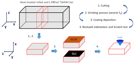
Figure 1.
Schematic representation of the experimental procedure where the Ti6Al4V bars are depicted: (1) in the as-manufactured shape (the z-axis represents the build direction in the LPBF process), (2) after cutting of the 15 × 13 × 5 mm coupons, (3) after deposition of the AlCrN or the DLC-based coating, and (4) during testing.
The surface conditions of all substrates were varied by acting on three parameters:
- The substrate fabrication method: LPBF and conventional rolling. This influences the microstructure of the material and, therefore, its mechanical properties [35,36] and the mechanical support provided to a thin coating. This ultimately affects the practical adhesion [37] of the coating. In fact, it has long been known that increasing the hardness of the substrate increases the critical load values measured by scratch testing [38]. Therefore, additively manufactured Ti6Al4V substrates were fabricated by the LPBF process in a SLM®280 machine (SLM Solution, Lübeck, Schleswig-Holstein, Germany) with the processing conditions described in [39]. The starting feedstock was a gas-atomized Ti6Al4V powder with 90% of the particles in the equivalent diameter range of 20–63 µm, as depicted in Figure 2. Its chemical composition is listed in Table 1.
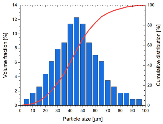 Figure 2. Volume fraction and cumulative distribution of the particle size of gas-atomized Ti6Al4V powders.
 - The substrate heat-treatment condition: after the LPBF fabrication, one set of bars was annealed at 740 °C × 130 min (i.e., below the β-transus) while another was solution at 1050 °C × 60 min (i.e., above the β-transus). The rolled bars were heat treated at 600 °C × 120 min as a stress-relieving heat treatment. In combination with the initial fabrication method, the heat treatment concurs to determining the final microstructure and, therefore, the mechanical properties of the substrate [35,40], extending the range of representative conditions probed in the adhesion tests.
- The surface finishing of the substrate, controlled by mechanical grinding with sandpapers of different grits. In fact, the substrate roughness is known to affect the adhesion of thin-film coatings [41,42]. The early reports indicate a tendency toward lower scratch adhesion and increased data scatter when the substrate roughness increases beyond Ra~0.05 µm [43,44], although sometimes the dependence between the roughness and scratch adhesion is more complex and non-linear [45]. Thus, all the rolled and LPBF substrates were cut in samples of 13 mm length, 15 mm in width, 5 mm in thickness after the heat treatment (Figure 1), and a wide spectrum of roughness was induced on their surfaces (before the deposition of the coatings) by grinding with SiC abrasive papers of different grit size. The surface roughness was measured on a surface area of 9.2 mm2 using a non-contact 3D profilometer (Taylor Hobson, Leicester, UK) equipped with the Mountains® platform software (Digital Surf, Besançon, France). The arithmetic mean height Sa (surface roughness) ranged between 0.11 and 1.6 μm. Each value was obtained through manual grinding operations by using SiC abrasive papers from P80 to P2400, and each surface was controlled by the non-contact 3D profilometer. The P80 and P180 were used to obtain rough substrates, while P1200 and P2400 were used to achieve low Sa values on bare substrate (smooth surfaces).
The experimental procedures described in this paper build on the results obtained in our previous work [46], where we focused on the tribological behaviour of these coatings as a function of the heat-treatment condition of the Ti6Al4V substrate, and represent a step forward in the analysis of the coating/substrate adhesion.

Table 1.
Nominal chemical composition (wt.%) of the gas-atomized Ti6Al4V powder as supplied by the manufacturer (Tekna®, Arendal, Norway).
Table 1.
Nominal chemical composition (wt.%) of the gas-atomized Ti6Al4V powder as supplied by the manufacturer (Tekna®, Arendal, Norway).
| Elements | Ti | Al | V | C | Fe | O | N | H |
|---|---|---|---|---|---|---|---|---|
| wt.% | Bal. | 6.5 | 4.1 | 0.01 | 0.2 | 0.1 | 0.01 | 0.001 |
Cross-sectional observations of the bar microstructure (surfaces on the yz-plane as shown in Figure 1) were performed by light microscopy (OM: DMi8, Leica, Wetzlar, Germany). The surfaces were mechanically ground (from P80 to P4000), polished with diamond pastes (from 3 to 0.25 μm grain size), and chemically etched with Keller’s reagent.
The hardness of bare substrates was measured by a Rockwell hardness tester (Zwick/Roell, Ulm, Germany) using a load of 150 kgf and a diamond cone indenter.
2.2. Coating Deposition Conditions
The deposition conditions of coatings were the same conditions as in our previous work [46]: (i) an AlCrN coating, and (ii) a DLC-based coating. The AlCrN film was deposited using a High-Power Impulse Magnetron Sputtering (HiPIMS) system (CemeCon CC800 HiPIMS) (CemeCon AG, Würselen, Germany) equipped with 4 sources and an Al70-Cr30 target within a vacuum chamber (10−5 mbar) heated at 470 °C. Following heating step with setpoint at 470 °C, and prior to coating phase, the substrates had been etched with an MF Argon plasma at low pressure. During coating, each cathode runs at 7500 W in argon and nitrogen atmosphere, with ratio of 2:1, and Bias voltage of −150 V. The DLC-based coating was deposited using a combined PVD and PE-CVD system (Hauzer HTC-1200) comprising 4 magnetron sputtering (MS) sources (2 × Cr + 2 × WC targets) and a pulsed bias power supply (60 kHz) for the plasma generation. The coating was deposited within a vacuum chamber (10−5 mbar) heated at 180 °C. Argon plasma etching was used to clean the substrate, followed by the sequential deposition of a metallic Cr adhesion layer and a W-C:H support layer by MS-PVD and a DLC top layer by PE-CVD, according to the conditions previously laid out in [46]. Cr runs at 5 kW, while WC at 6 kW, each. Cr deposition is conducted in pure Ar plasma while W-C:H is with Ar+C2H2. For a-C:H layer, only C2H2 is used as process gas, voltage controlled at −700 V. Table 2 summarizes the nomenclatures of coated substrates on which Rockwell VDI and scratch tests were carried out. The labels “7_” and “10_” indicate the substrates annealed at 740 °C and solutioned at 1050 °C, respectively, while “R_” represents the rolled substrates.
Table 2.
List of samples and their designation.
2.3. Characterization of the Coated Systems
A Rockwell indentation test, defined by the VDI 3198 standard, was used to establish the coating/substrate adhesion, as discussed in the Introduction section. As shown in Figure 1, a conical diamond was loaded onto the coated surfaces (yz-plane, Figure 1) using the ZHR Rockwell machine (Zwick/Roell, Ulm, Germany) with a load of 150 kgf. The damages to the coating were evaluated by (i) comparing the imprints observed through optical microscopy (OM) with the failure chart displayed in Figure 3 and (ii) performing a statistical analysis of both the radial cracks extending out of the Rockwell indentation boundary and the areas where the coating was detached. For each investigated condition, the coating damages were evaluated on two different Rockwell indentations. Figure 3 shows the adhesion classes grouped into acceptable (HF1–HF4) and unacceptable failure (HF5 and HF6) based on the number of cracks and detached (or delaminated) areas. The HF1 and HF2 classes are differentiated by the density of microcracks present at the edge of the Rockwell indentation. For the adhesion class HF3, some small areas of delamination must be present along the Rockwell indentation boundary. If these areas are present all around the indentation, the adhesion class is HF4. Lastly, HF5 and HF6 adhesion classes present extensive detached areas around the Rockwell imprint, forming a continuous area in HF6. This statistical analysis was performed due to (i) the uncertainty in the damage classification (from HF1 to HF6, Figure 3) caused by the magnification necessary to contain the entire imprint (resulting in low resolution, especially for the rougher substrates), and (ii) the lack of relevant literature.
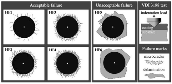
Figure 3.
Failure chart illustrating coating damages observed during the Rockwell indentation test (Reprinted from reference [12]).
Regarding the statistical analysis, the cracks along the boundary of the Rockwell indentation (Figure 4) were counted and then normalized by the length of the indentation. The number of cracks per unit length was considered, accounting for the variation in the Rockwell imprint due to the substrate hardness. The imprint diameter increases as substrate hardness decreases. Similarly, the percentage of detached areas (or delamination areas) was evaluated by considering the area ratio:
where the is the sum of the delamination areas within the circular crown (represented by the yellow dotted circumference in Figure 4), and the is the area of the circular crown. The radius of this circular crown was set to be 15% higher than the Rockwell indentation radius to accommodate the varying hardness values of the various Ti6Al4V substrates. The choice of 15% ensured that the largest detached area fell within the circular crown. Figure 4 is a representative image showing the damages (cracks and detached areas) considered in the present study and the RRC for each investigated condition (Table 2).
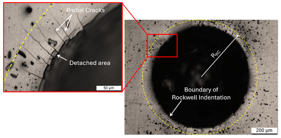
Figure 4.
Rockwell indentation on 10_AlCrN sample reveals the count of radial cracks per unit length along the Rockwell imprint boundary, as well as the detached areas observed within the same imprint. The yellow dotted circumference outlines the radial crown used to assess the percentage of the delamination (detached) areas, whit RRC representing the radius of the radial crown.
The Rockwell imprints and the coating cross-sections were examined using focused ion beam scanning electron microscopy (FIB-SEM: Auriga Compact FIB-SEM, Zeiss, Oberkochen, Germany) equipped with the Ultim® Extreme detector (Oxford Instruments, Abingdon, UK). Each sample was tilted by 54° to ensure that the surface was perpendicular to the FIB beam. FIB-SEM micrographs were captured with the sample tilted at 36° relative to the electron beam axis. Each investigated area was milled by 20 keV Ga+ ions with a current of 5 nA, achieving a milling depth of 10 μm. Chemical characterization of both the coating cross-sections and the detached areas was carried out using EDX analysis. Additionally, Auger Electron Spectroscopy was employed to assess the distribution of the Al, Cr, and N elements within the AlCrN thin film. The incident electron beam was emitted from a W filament operated at 3.1 A current and was accelerated to an energy of 3 keV at a beam current of 700 nA. Depth profiling was obtained by sputtering with an Ar+ ion beam operated at 5 keV energy and 30 nA ion beam current, covering an area of 0.5 × 0.5 mm2, resulting in a sputtering rate of approximately 5 nm/min.
Another adhesion test was the scratch test. It was performed with a Micro-Combi Tester apparatus (Anton Paar Tritec, Corcelles, Switzerland) operating with a conical diamond indenter with a 120° opening angle and a 200 µm-radius rounded tip. Three scratch tracks were performed on one sample for each coating type and each substrate condition, with a scratch length of 6 mm, a scratch speed of 6 mm/min and a load range from 0.02 N to 30 N. The critical loads were identified by visual inspection of the scratch tracks with an optical microscope at a magnification of 200×. Instrumental recordings of acoustic emission and tangential force, as well as the profiles of the total and residual penetration depths of the tracks, obtained by performing pre- and post-scans of the sample with the same scratch tip at a fixed load of 0.02 N, assisted in the analysis of the tracks. The critical loads were defined as the onset points for crack formation (LC1), chipping of the coating (LC2), and continuous spallation across the track width (LC3), according to the ISO 20502 standard [47]. In addition, a further critical load was defined at the point where the substrate is continuously exposed along the track (LDelam).
3. Results and Discussion
3.1. Structure and Microstructure of the Substrates and Thin Films
Figure 5 displays the microstructures of the LPBF-manufactured Ti6Al4V bars (Figure 5a,b), annealed at 740 °C × 130′ (Figure 5a) and solutioned at 1050 °C × 60′ (Figure 5b), and the microstructure of the rolled Ti6Al4V bar (Figure 5c), subjected to stabilization heat treatment at 600 °C × 120′ (Figure 5c). The microstructure of annealed bare Ti6Al4V substrates (Figure 5a) showed columnar β-grains (indicated by white dotted lines) aligned parallel to the build direction (from the bottom to the top region of the component) due to their epitaxial growth during the melt pool solidification [48]. The high cooling rates (104–106 K/s, [3]) typical of the molten pool solidification induce an unintentional β → α′-martensite transformation, where the brittle and needle-like α′-martensite laths are arranged in a hierarchical structure, forming a crosshead pattern within the columnar β-grains [3,49,50]. The annealing treatment at 740 °C × 130′ partially decomposed the as-built α′-martensite (Figure 5a) into the α + β laths because the alloying elements diffused from the supersaturated α′-martensite. The diffusion of V (β-stabilizer) from the α′-martensite lattice formed the β-phase along the boundaries of the α-laths, whilst Al (α-stabilizer) promoted the α′ → α transformation [40]. When the heat treatment temperature exceeded the β-transus, the columnar β-grains recrystallized into equiaxed grains (Figure 5b), with αGB-phase (GB: Grain Boundary) delineating their boundaries. The cooling in argon gas from the β-region resulted in a β → α + β transformation, creating a Widmanstätten structure of α + β colonies that nucleated on αGB boundaries and grew into the equiaxed β-grain.
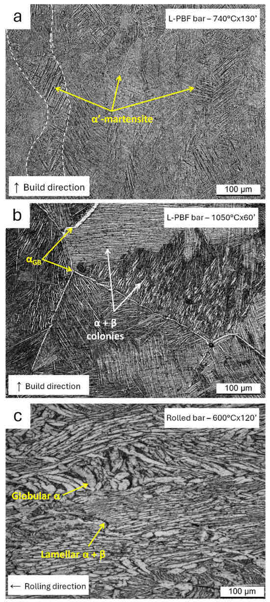
Figure 5.
OM micrographs of the microstructures of the LPBF-manufactured (a,b) and rolled (c) Ti6Al4V bars heat-treated at: (a) 740 °C × 130′, (b) 1050 °C × 60′, (c) 600 °C × 120′.
Consistent with the results presented in [35], the LPBF Ti6Al4V substrates heat-treated below and above the β-transus temperature showed similar hardness values (40 ± 2 HRC and 39 ± 1 HRC) despite the different microstructural characteristics (Figure 5a,b). A detailed discussion related to this aspect was reported in [39]. The microstructure of the rolled substrates was elongated along the rolling direction and was characterized by a mixture of α + β colonies and α-globular phases (Figure 5c), as also reported in [51,52]. This microstructure can be regarded as representative of the as-rolled condition because the post-process heat treatment at 600 °C × 120′ reduced the internal stress without altering the microstructure, as is well documented in the literature [53,54]. Rockwell measurements indicated an average hardness of 40 ± 3 HRC.
After grinding with SiC papers, all types of bare substrates exhibited a surface roughness, quantified through the arithmetic mean height Sa, that varied from a maximum of (1.6 ± 0.2) μm (i.e., the rougher surface in Figure 6a) to a minimum of (0.11 ± 0.05) μm (i.e., the smoother surface in Figure 6b), as previously mentioned in Section 2. The smoother bare substrates obviously showed lower roughness amplitude, including root mean square height (Sq) and maximum height (Sz). The surface roughness values remained practically unchanged (within error range) after depositing the DLC-based and the AlCrN coatings (see Table 3).
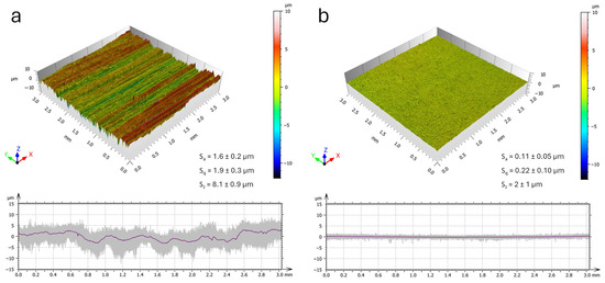
Figure 6.
Three-dimensional surface morphology of the roughest (a) and smoothest (b) substrates. The purple lines indicate the average of the 2D profiles (grey lines) extracted from the 3D maps.
Table 3.
Surface roughness values (μm) of both the smoothest and roughest substrates before and after the coating deposition.
Figure 7 depicts the FIB cross-sections of both the AlCrN (Figure 7a) and DLC-based (Figure 7b) thin films, highlighting the influence of smooth (Figure 7a) and rough (Figure 7b) substrates. As extensively investigated by the authors in [46], both coatings followed the profile of the substrate surface, confirming the substantial absence of change in the roughness values after deposition, as shown in Table 3. Specifically, on the rougher surfaces, defects could be only observed in the first layers of the multi-layered architecture (white arrows in Figure 7b). As evidenced by the EDX linescans (Figure 6b), the region between the substrate and the DLC top layer is formed by a multi-layered architecture comprising Cr-based, WC-based, and WC-C layers [46]. It is remarked that, because of the 36–tilt of the sample in the FIB-SEM during the acquisition of the EDS linescans, and because of the finite size of the X-ray generation region, a faint signal of W and Cr was detected in Figure 6b also in the DLC top layer, but this should be regarded just as a measurement artefact.
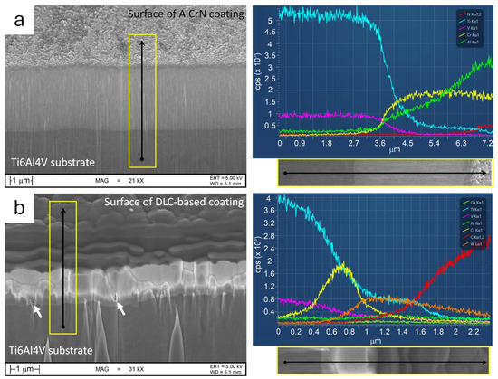
Figure 7.
SEM micrographs showing the FIB cross-sections of the AlCrN film deposited on a smooth substrate (a) and the DLC-based coating deposited on a rough substrate (b) with corresponding EDS linescans acquired along the lines indicated by the black arrows. The with arrows indicate the defects present in the first layer of the coating.
The intermediate layers (Cr-based, WC-based, and WC-C) facilitated a smooth transition between the substrate and the DLC top layer in terms of chemical composition and mechanical properties. The overall thickness of DLC-based coating is approximately 2.1 ± 0.1 µm, where the top DLC coating is 1.1 ± 0.1 µm thick. In contrast, the AlCrN film, which was 2.8 ± 0.2 µm thick, was directly deposited on the Ti6Al4V substrate. The EDS spectrum (Figure 7a) indicated no significant elemental segregation along the cross-section of the AlCrN coating. The increased signal from the N and Al elements at the top region of the coating was an effect conferred by the sample’s inclination with respect to the FIB beam.
Additionally, Figure 7 presents the surface morphologies of the coatings. The AlCrN coating exhibited several angular facets that corresponded to the extremities of the fine columnar grains, as also supported by the investigations in [46,55]. Conversely, the DLC-based coating showed a cluster morphology typical of this type of coating [56].
3.2. Analysis of the Coating/Substrate Adhesion: Rockwell Indentation Test
Figure 8 shows the Rockwell imprints performed on smooth 7_DLC (Figure 8a) and rough 10_AlCrN (Figure 8b) substrates, as representative cases of all investigated conditions (Table 2). Due to the high load applied during Rockwell measurements (150 kgf) and the low thickness of both hard coatings (Figure 7), the HRC values remained unchanged compared to the bare substrates. However, each indentation exhibited a variable diameter, depending on the substrate resistance: the indentation diameter increased as the substrate hardness decreased. Consequently, it was necessary to account for the variation in the RRC radius with the Rockwell indentation radius (Equation (1)).
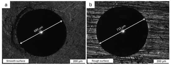
Figure 8.
OM micrographs of the Rockwell imprints acquired on smooth 7_DLC (a) and rough 10_AlCrN (b) substrates.
Both Rockwell indentations were observed with an OM, first for comparison with the failure chart (Figure 3) and then to determine the adhesion class. When comparing the 7_DLC and 10_AlCrN substrates to the failure chart, the coating/substrate adhesion could be misclassified as HF1, since both coatings appeared undamaged. In this context, it can be concluded that the magnification required to acquire the entire imprint in the OM micrograph prevented an accurate damage assessment, as previously discussed in the Introduction and further supported by the following results.
Figure 9a,b illustrate how the number of cracks per unit length, identified through the OM, varied with the surface finish of both the LPBF-manufactured (Figure 9a) and rolled (Figure 9b) substrates. When the surface roughness increased from the smoothest to the roughest sample, the number of cracks per unit length initially rose due to the higher contact pressure induced by the Rockwell indenter. In fact, the contact pressure was considerably higher on a rougher than on a smoother surface [57,58]. However, when the surface roughness (Sa) exceeded approximately 1.0 μm (see Figure 6a), the number of cracks decreased due to the presence of deep dales aligned radially with respect to the Rockwell indentation boundary (Figure 9c,d). Indeed, Figure 9c,d show that only radial cracks which were not parallel to the dales were observable and, therefore, countable during the statistical analysis. Thus, the decrease in the number of cracks on very rough surfaces was likely an artefact due to the very limited depth of field of an OM, which made it hard to detect cracks propagating along the deepest dales.
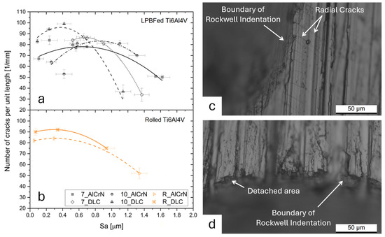
Figure 9.
(a,b) Number of cracks per unit length versus the surface roughness of both the LPBF-manufactured (a) and rolled Ti6Al4V (b) samples. 7_ and 10_ indicate the Ti6Al4V substrates heat treated at 740 °C and 1050 °C, respectively. R_ represents the rolled substrates heat treated at 600 °C. (c,d) OM micrographs showing the edge of a Rockwell indentation carried out on the roughest Ti6Al4V substrate (Sa = 1.6 ± 0.2 μm) coated with the AlCrN film.
These statements were confirmed by comparing OM (Figure 10a,b) and SEM (Figure 10c,d) micrographs of the same regions of a Rockwell indentation. The higher depth of field of a SEM, in fact, revealed radial cracks within the dales (compare the areas marked by red rectangles in Figure 10a,c) which were not detectable by OM. In fact, the red rectangle marks a deep dale (Figure 10a) where no cracks were detected by OM even when the focal plane was adjusted on the bottom region of the same dale (Figure 10b). The magnified SEM (Figure 10d) view of Figure 10a shows that an undetected crack was also present on the peaks (Figure 10d) of the surface roughness profiles. The same conclusions can be drawn for the dale indicated by the yellow arrow in Figure 10a,c,d.
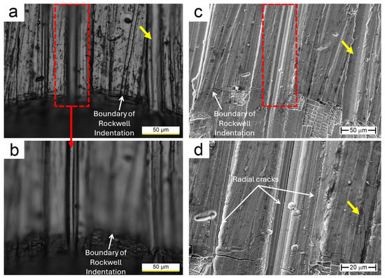
Figure 10.
Optical (a,b) and SEM (c,d) micrographs depicting the same region of the Rockwell indentation performed on the rougher substrate coated with AlCrN thin film. Optical micrographs (a,b) show two different focal planes to reveal the bottom zone of the dale. SEM micrographs were acquired at 1 kx (c) and 2.5 kx (d) magnification. The yellow arrows indicate the dale containing the cracks unrevealed through the optical microscope.
Additionally, the presence of deep dales and tall peaks influenced and/or governed the crack propagation, as observable in Figure 11. Dales and peaks radially aligned with the Rockwell indentation accommodated the cracks and facilitated their propagation (Figure 11a,c), likely acting as points of stress concentration. When the dales were not aligned along the radial direction, the cracks propagated across different peaks and dales, sometimes deflecting their path (yellow arrows in Figure 11b–d). Additionally, the rougher surfaces promoted the initiation of new cracks (red arrows in Figure 11b–d) due to their ability to concentrate stresses [59]. Considering the new radial cracks revealed by SEM observations (Figure 10 and Figure 11), the number of radial cracks per unit length on the rougher samples (Sa > 1 μm in Figure 9) increased by approximately of 25 ± 5%, when compared with the values measured by optical microscopy. However, this increment did not significantly alter the trend discussed above or the coating/substrate adhesion results. Within this framework, however, the VDI 3198 standard appears to have further limitations in evaluating coating/substrate adhesion when the substrates have rough surfaces.
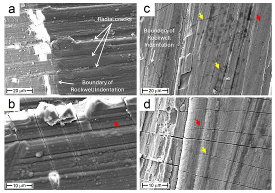
Figure 11.
SEM micrographs of DLC-based (a,b) and AlCrN (c,d) coatings deposited on the rougher substrates, acquired at 2.5 kx (a), 2 kx (c), and 5 kx (b,d) magnifications. The yellow and red arrows point to cracks that propagated across different peaks and that originated from the rough surface, respectively.
Regarding the LPBF-manufactured substrates, the different heat treatment conditions did not significantly influence the adhesion of the AlCrN and DLC-based coatings, as also supported by the investigations performed in [46]. Similarly, both types of coatings showed comparably good adhesion to the LPBF-manufactured and the rolled Ti6Al4V substrates, as evidenced by the similar numbers of cracks found at similar roughness levels (compare Figure 9a and Figure 9b) [60]. These findings were supported by the length of the radial cracks, which varied from the minimum of 55 ± 20 μm to the maximum of 75 ± 30 μm regardless of the analyzed coating/substrate combination [61,62]. Therefore, it can be concluded that the microstructural differences between the substrates (LPBF-manufactured and rolled, with different heat-treatment conditions, Figure 5) did not significantly affect their plastic deformation behaviour.
Focusing on the detached areas distributed along the Rockwell indentation in all coating/substrate combinations, Figure 12 demonstrates an exponential increase in their percentage with the number of cracks starting from approximately 60 cracks/mm. Below this crack density, the percentage of detached area seemed to be fixed at approximately 0.6% even considering the increase in the number of cracks (25 ± 5%) discussed in Figure 11. Nevertheless, both the AlCrN and the DLC-based films were characterized by an acceptable failure, comparable to the HF3 adhesion class even on the roughest substrates (refer to Figure 3). In fact, all coating/substrate conditions showed small-sized delamination areas unevenly distributed along the Rockwell indentation boundary, which were undetectable at lower magnifications (see Figure 8).
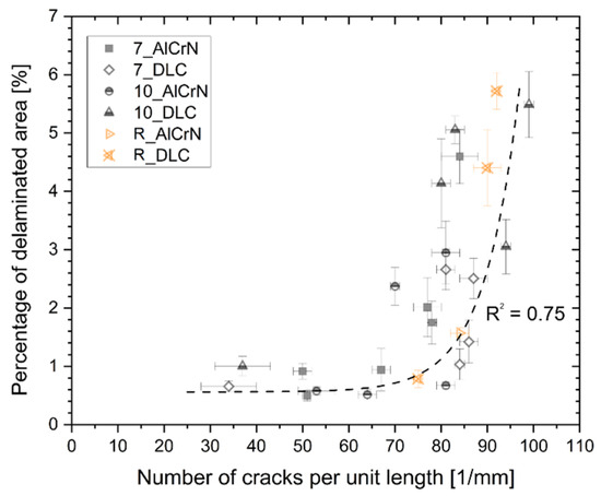
Figure 12.
Number of cracks per unit length versus the percentage of the detached area for AlCrN and DLC-based coatings deposited on both the LPBF-manufactured (7_ and 10_) and Rolled (R_) substrates. 7_ and 10_ denote the LPBF-manufactured Ti6Al4V substrates heat treated at 740 °C and 1050 °C, respectively, while R_ represents the cast substrates heat treated at 600 °C.
Figure 13 shows a representative SEM micrograph of the damaged AlCrN coating where the white dotted lines outline the circumferential crack along the edge of the Rockwell indentation, and yellow arrows indicate a circumferential crack inside the indented area. Several radial cracks also propagated outwards, consistent with the images of Figure 9. As supported by Thomsen et al. [63], the formation of radial cracks indicates a strong bonding between the substrate and the coating. In fact, under the driving force of the radial cracking pattern, i.e., the circumferential stress induced in the purely elastic coating by the piling up of the elastic-plastic substrate immediately outside the indented area, crack propagation occurred within the coating rather than along the coating/substrate interface. FIB cross-sections presented in our previous work [46] supported these observations: no crack was indeed found at the coating/substrate interface in both the AlCrN and the DLC-based coatings. Specifically, in the AlCrN coating the radial cracks propagated down from the surface along the boundaries of the columnar grains, then deflected parallel to the substrate before reaching the interface. EDS maps (Figure 13) further support this interpretation, as Cr and N elements were detected within the detached area. However, the signal of Ti and V also emerged because the residual coating thickness was low enough for the electron beam to excite the emission of characteristic X-rays from the underlying substrate.
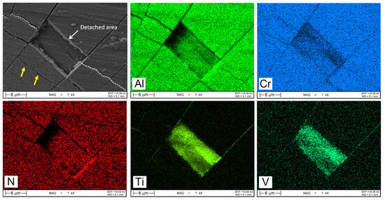
Figure 13.
SEM micrographs of AlCrN coating after the Rockwell indentation test and EDS maps of the same region. The yellow arrows indicate circumferential cracks inside the indented area, while white dotted lines retrace the circumferential crack along the indentation edge.
The AES (Auger Electron Spectroscopy) spectrum in Figure 14 suggested that the crack deflection was associated with, and likely caused by, a higher concentration of N in the bottom region of the coating, i.e., near the coating/substrate interface. The improved strength conferred by the higher atomic concentration of N increased the resistance to plastic deformation [64]. Moreover, Figure 13 shows that delamination areas were contained between two adjacent and consecutive radial cracks. This observation supported the trends discussed in Figure 12, as a higher number of cracks per unit length reduced the distance between two adjacent radial cracks and, consequently, facilitated the detachment of portions of coatings.
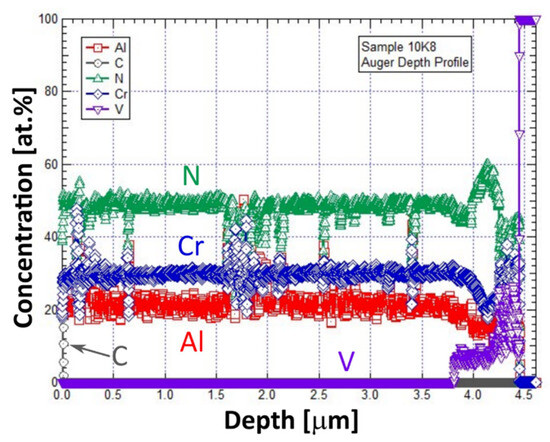
Figure 14.
Depth profiling of the AlCrN coating’s composition by Auger Electron Spectroscopy.
Figure 15 shows the FIB cross-section of the DLC-based coating, highlighting how the multi-layered architecture influenced the secondary crack propagation. In detail, cracks tended to propagate within the WC-C layer rather than at its interface with the DLC top layer or at the coating/substrate interface. As discussed in our previous work [46], all detached areas always presented a residual thin layer adherent to the substrate. In fact, EDS spectra confirmed the presence of W and Cr in the delaminated areas of the DLC-based coating. For this reason and considering that each delamination area did not really expose the underlying substrate, each coating analyzed in this study could be classified under the HF2 adhesion class rather than in the HF3 one as reported by the VDI 3198 standard.
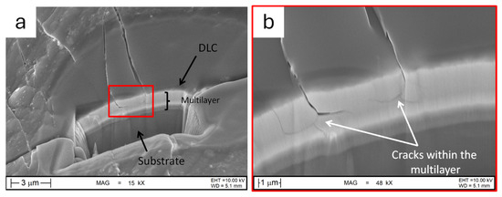
Figure 15.
SEM micrographs of the detached area of the DLC-based (a) and the AlCrN (b) coatings.
3.3. Analysis of Scratch Test Results
Confirming the preliminary findings that we had previously reported in [46], the scratch tests produced three types of critical loads, irrespective of the roughness of the substrate: chipping along the track sides, damage across the entire width of the track, and complete delamination (Figure 16a–d). Their onset was, respectively, associated with the critical loads LC2, LC3 (following the classification in the ISO 20502 standard), and LDelam. Magnified views (Figure 16(a1,a2,d1)) show that, for both the DLC-based and the AlCrN coatings, the track-side chipping associated with the LC2 load and the damage across the track associated with the LC3 load were a consequence of compressive buckling. This is a well-known phenomenon for thin, hard films on ductile substrates. As described by Bull and Berasetegui [28], compressive buckling occurs when a ductile substrate bends ahead of the indenter under the applied stress, causing compressive failure in the thin film. This is manifested through the formation of curved transverse cracks and the delamination of fragments between consecutive cracks, as it was indeed found in Figure 16(a1,a2,d1). When the cracking and delamination damage became particularly extensive, the fractured coating was subsequently crushed when the indenter moved over it, and eventually, the coating was entirely removed, leading to the identification of the delamination load (Figure 16(a2,d1)). Further, on the smoothest samples, it was possible to identify the critical load for the formation of the first cracks along the track sides (LC1 according to ISO 20502). However, these could not be identified on rough substrates because the smallest cracks occurring at low loads were not discernible, as also revealed by the Rockwell indentations (VDI test).
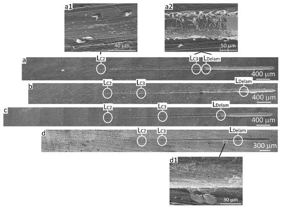
Figure 16.
SEM overviews (montage of images) of the scratch tracks of coatings on L-PBF substrates heat treated at 740 °C for 130 min: DLC-based films on substrates with Sa = 0.90 µm (a), 0.66 µm (b), and 0.52 µm (c), and AlCrN film on a substrate with Sa = 0.56 µm (d), with details of the failures (a1,a2,d1) at the marked locations.
As shown in Figure 17, the smallest cracks on rough samples are difficult to detect even by SEM imaging (see circle), and even when viewing them at a location situated well beyond the LC1. In fact, the contrast of the tiny cracks is overshadowed by the morphological contrast due to roughness. Therefore, not even SEM imaging would allow an accurate identification of the crack onset point. Moreover, systematic SEM inspection for the identification of critical loads would be impractical for any actual usage of the scratch adhesion test. Thus, all subsequent analyses focused only on the values of LC2, LC3 and LDelam.
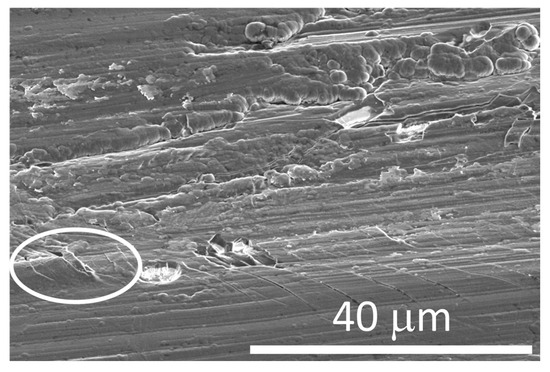
Figure 17.
SEM micrograph of microcracks (see circle) along the side of a scratch track on the DLC-based film deposited on a substrate with Sa = 0.90 µm, around the LC2 location.
The chipping events occurring after the LC2 critical load in the DLC-based film involved the outermost DLC and WC/C layers (Figure 18a–c), as for the VDI tests In the AlCrN film, most of the coating thickness spalled off through intercolumnar cracks propagating across the coating, but the crack then deflected into the coating above the substrate, which was not immediately exposed (Figure 18d). Indeed, the brittle coating (with some cracks) is still visible at the bottom of the spalled area in Figure 18d.
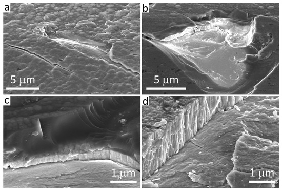
Figure 18.
SEM micrographs showing details of side chippings along the scratch tracks of coatings on L-PBF substrates heat treated at 740 °C for 130 min: DLC films on substrates with Sa = 0.52 µm (a), 0.66 µm (b), and 0.90 µm (c), and AlCrN film on a substrate with Sa = 0.56 µm (d).
When complete delamination occurred, on the other hand, the entire coating was removed, and the substrate was uncovered (Figure 19: the arrows indicate the uncovered substrate at the LDelam critical load).
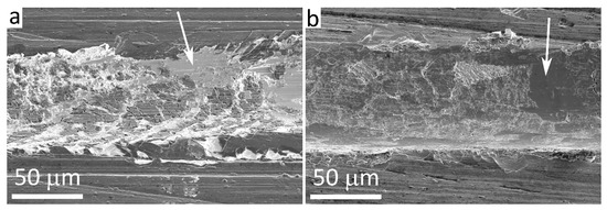
Figure 19.
SEM micrographs showing details of the delamination onset in the scratch tracks on the DLC (a) and the AlCrN (b) coating on L-PBF substrates heat treated at 740 °C for 130 min, with Sa = 0.66 µm (a) and Sa = 0.56 µm (b). The arrows indicate areas of uncovered Ti-6Al-4V substrate.
The critical load values for the two types of coatings were similar on all substrate types, i.e., rolled and LPBF Ti6Al4V heat-treated above and below the β-transus (Figure 20a–c for the DLC-based films and Figure 20d–f for the AlCrN films). As already observed for the Rockwell indentations, the type of substrate was irrelevant for the cracking behaviour in the scratch test, probably because the LPBF and rolled Ti6Al4V samples showed the same hardness values (Figure 5).
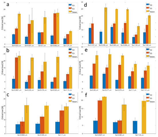
Figure 20.
Summary of the critical loads LC2, LC3, and LDelam as a function of the arithmetic mean roughness Sa of the substrate–DLC-based films on LPBF substrates heat-treated at 740 °C/130 min (a) and 1050 °C/60 min (b), and on rolled substrates (c); AlCrN films on LPBF substrates heat-treated at 740 °C/130 min (d) and 1050 °C/60 min (e), and on rolled substrates (f). In a few cases (panels (f) and (b)), AlCrN films did not exhibit identifiable LC3 events before delamination; in one case (panel (b)) there was no delamination of the AlCrN film before the end of the scratch test.
Looking more specifically at the relation between critical loads and roughness, the LC2 and LC3 values did not exhibit any statistically significant trend as a function of the arithmetic mean height of the substrate profile (Figure 20b,c). Indeed, the p-values for the null hypothesis that the slope of the critical load vs. Sa trends is not different from zero, calculated by performing a linear regression to the data with Matlab (R2024a), were well above the 0.05 level that is usually assumed as a reasonable (though arbitrary) threshold for statistical significance.
Conversely, there was a weak but discernible trend of decreasing delamination load (LDelam) with increasing roughness (Figure 20a). This could be inferred also from the bar charts in Figure 19, where in most panels, the average LDelam value tended to decrease with increasing substrate roughness, although in a few cases (panels a and f), it was more difficult to identify a distinct trend. The adjusted regression coefficient of the linear fit to the LDelam vs. Sa plot was consistently low ( = 0.249), confirming that the data was highly scattered and the confidence on the regression parameters was limited. Nonetheless, the existence of a negative slope seemed statistically significant (p ≈ 0.006). This would therefore match with the usual assumption that an increase in roughness worsens the practical adhesion of thin-film coatings by causing larger stress concentrations. However, the high scatter of the data, which could be contributed by the intrinsically heterogeneous nature of the roughest surfaces as well as by the microstructural features of LPBF materials in terms of typical defects (gas pores, lack-of-fusion [65], made this correlation more difficult to perceive, and only with the delamination load. The defects can indeed act as weak spots buried below the coatings, which might have caused failure to start a bit earlier or later in different specimens or different areas of a given specimen. As a future development, it could be interesting to check how this relation would play out with different substrate materials. Ti and its alloys indeed have a peculiar behaviour, related both to their hardness, and to the few available slip systems of the hexagonal lattice (predominant α-phase), which restricts both their plastic deformability and the ability to work harden. This might limit the consequences of inducing ever-higher contact pressures with rougher surfaces. More ductile substrates with more pronounced hardening abilities could therefore be explored in the future.
The consequence of the above analysis is also that, despite the noted limitations, the scratch test was a bit more sensitive than the VDI test in detecting an effect of surface roughness on adhesion strength. In the VDI test, in fact, all samples belonged to the same adhesion class, and although there was a monotonic correlation between the number of radial cracks per unit length and the extent of delaminated area, this trend was not associated with a monotonic increase in roughness. Probably, the scratch test could discriminate more effectively the effect of roughness because it induced the complete removal of the coating, which never happened in the VDI test. As discussed previously in Section 3.2, the delaminations identified by optical microscopy around the Rockwell indentation marks, when viewed by SEM, turned out to be chippings confined within the coating. Therefore, they were comparable to the LC2 and LC3 events of the scratch test rather than to the eventual coating delamination.
Within this framework, no significant correlations (Figure 21a,b) were found between the number of radial cracks per unit length and the critical loads related to the scratch tests likely due to the different sensitivity of the critical loads (Figure 20) and the number of cracks (Figure 9) to the substrate roughness.
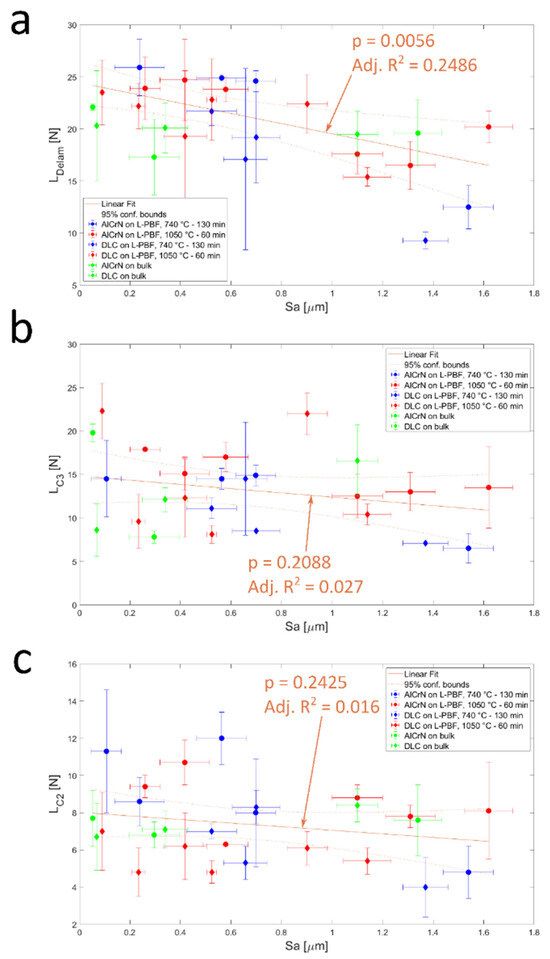
Figure 21.
Critical loads LDelam (a), LC3 (b), and LC2 (c) measured by scratch testing as a function of the arithmetic mean height (Sa) of each sample, with the corresponding linear regressions, the 95% confidence bounds, the adjusted R2 values, and the p-values associated with the regression slope.
On the contrary, Figure 22c,d exhibits a possible correlation between the percentage of delaminated area, obtained from Rockwell VDI test, and the critical load of delamination (LDelam.). The exponential fits reveal that the fraction of coating detached from the Ti6Al4V substrates in the VDI test increased with the critical load of delamination. On the other hand, the R2 of around 0.28 confirms that the results were scattered and the confidence on the exponential fit was limited.
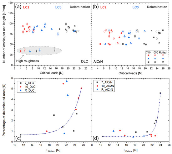
Figure 22.
(a,b) Number of cracks per unit length in the VDI test vs. the critical load in the scratch test for DLC-based (a) and AlCrN (b) coatings. (c,d) Percentage of delaminated area in the VDI test vs. the LDelam load in the scratch test.
4. Conclusions
In this work, we evaluated a new approach to the Rockwell indentation method to test the adhesion of thin-film coatings based on the VDI standard and a statistical analysis of the coating damages, and we studied its correlation with the scratch test results. Indentation and scratch tests were performed on LPBF and rolled Ti6Al4V samples in various heat treatment conditions and with different surface finishes, using both a DLC-based and an AlCrN coating.
From the results, the following conclusions can be drawn:
- The films showed good adhesion regardless of the roughness and the microstructure of the LPBF and rolled Ti6Al4V substrates. Where delamination areas were formed, a portion of both the DLC-based and the AlCrN coatings remained well adherent to the substrates. The extension of these delaminated areas displayed a monotonic correlation with the number of radial cracks per unit length, regardless of the surface finishes.
- Optical microscope observations at low magnification, as dictated by VDI 3198 standard, suggested a better adhesion class than was truly obtained when investigating the sample surfaces in more detail.
- Values of surface roughness (Sa) higher than 1 μm limited the applicability of VDI3198 standard in detecting the coating damages. Deep dales and high peaks aligned with the radial direction of the Rockwell indentation hid the presence of radial cracks and, therefore, led to an underestimation of the actual damage. Additionally, in the scratch test a high surface roughness made the smallest cracks associated with the critical load LC1 not discernible.
- Although the films were similarly damaged through cracks and delaminations during both the scratch test and the Rockwell indentation, the scratch test was a bit more sensitive in detecting the effect of surface roughness on adhesion strength. It was indeed capable of probing the complete removal of the coating, and a weak negative correlation emerged between the delamination load and the arithmetic mean roughness amplitude of the substrate surface. Additionally, there is a weak positive correlation between the percentage of delaminated area in the VDI test and the critical load of delamination in the scratch test. Nevertheless, when trying to correlate directly the percentage of delaminated area in the VDI test to the substrate surface roughness, we could not find a significant correlation, probably because of the large scatter of the data.
Author Contributions
Conceptualization: E.G., G.B. and E.C.; data curation: M.F.B., E.G. and G.B.; formal analysis: M.F.B., E.G. and G.B.; funding acquisition: E.G. and E.C.; investigation: M.F.B., E.G. and G.B.; project administration: E.G., G.B. and E.C.; resources: G.B., E.C. and P.C.; supervision: E.C., G.B. and E.C.; validation: E.G., G.B., M.F.B. and E.C.; visualization: M.F.B., E.G. and G.B.; writing—original draft: M.F.B., E.G. and G.B.; writing—review and editing: M.F.B., E.G., G.B., E.C. and P.C. All authors have read and agreed to the published version of the manuscript.
Funding
The project was granted by the University of Parma through the action Bando di Ateneo 2023 per la ricerca, co-founded by the National Recovery and Resilience Plan (NRRP), Mission 4, Component 2, Investment 1.5.—Call for tender No. 3277 of 30 December 2021 of the Italian Ministry of University and Research founded by European Union–NextGenerationEU.
Data Availability Statement
The original contributions presented in this study are included in the article.
Acknowledgments
Many thanks to Antonio Ballestrazzi (Department of Physics, Informatics and Mathematics, University of Modena and Reggio Emilia, Italy) for performing the Auger depth profiling analysis.
Conflicts of Interest
Paolo Colombi was employed by Lafer S.p.A. The remaining authors declare that the research was conducted in the absence of any commercial or financial relationships that could be construed as a potential conflict of interest.
Abbreviations
The following abbreviations are used in this manuscript:
| AES | Auger electron spectroscopy |
| CAD | Computer-aided design |
| CM | Conventional manufacturing |
| DLC | Diamond-like carbon |
| EDS | Energy-dispersive spectroscopy |
| FIB-SEM | Focused ion beam scanning electron microscopy |
| GB | Grain boundaries |
| HiPIMS | High-power impulse magnetron sputtering |
| LPBF | Laser powder bed fusion |
| PE-CVD | Plasma-enhanced chemical vapour deposition |
| PVD | Physical vapour deposition |
| MS | Magnetron sputtering |
| VDI | Verein Deutscher Ingenieure |
References
- Haydar, H.J.; Al-Deen, J.; AbidAli, A.K.; Mahmoud, A.A. Improved Performance of Ti6Al4V Alloy in Biomedical Applications—Review. J. Phys. Conf. Ser. 2021, 1973, 012146. [Google Scholar] [CrossRef]
- Donachie, M.J. Titanium: A Technical Guide, 2nd ed.; ASM International Materials Park: Novelty, OH, USA, 2000. [Google Scholar]
- Ghio, E.; Cerri, E. Additive Manufacturing of AlSi10Mg and Ti6Al4V Lightweight Alloys via Laser Powder Bed Fusion: A Review of Heat Treatments Effects. Materials 2022, 15, 2047. [Google Scholar] [CrossRef]
- Ren, X.P.; Li, H.Q.; Guo, H.; Shen, F.L.; Qin, C.X.; Zhao, E.T.; Fang, X.Y. A Comparative Study on Mechanical Properties of Ti–6Al–4V Alloy Processed by Additive Manufacturing vs. Traditional Processing. Mater. Sci. Eng. A 2021, 817, 141384. [Google Scholar] [CrossRef]
- Shunmugavel, M.; Polishetty, A.; Goldberg, M.; Singh, R.; Littlefair, G. A Comparative Study of Mechanical Properties and Machinability of Wrought and Additive Manufactured (Selective Laser Melting) Titanium Alloy—Ti-6Al-4V. Rapid Prototyp. J. 2017, 23, 1051–1056. [Google Scholar] [CrossRef]
- Xin, L.K.; Kamarudin, M.; Nosbi, N.; Yosuf, A.H.M.; Wan Ali, W.F. Enhancing turbine blade durability: Evaluating protective ceramic coatings for Ti6Al4V alloy. Tribol.-Mater. Surf. Interfaces 2024, 18, 256–269. [Google Scholar] [CrossRef]
- Sharma, P.; Mishra, S.K.; Ramkumar, J. Characterization and wear performance of advanced AlTiSiN-based coated cutting tools in dry machining of Ti-6Al-4V alloy. J. Mater. Process. 2025, 150, 485–500. [Google Scholar] [CrossRef]
- Chalker, P.R.; Bull, S.J.; Rickerby, D.S. A Review of the Methods for the Evaluation of Coating-Substrate Adhesion. Mater. Sci. Eng. A 1991, 140, 583–592. [Google Scholar] [CrossRef]
- Verein Deutscher Ingenieure Normen, VDI 3198; VDI-Verlag: Dusseldorf, Germany, 1991.
- Lenz, B.; Hasselbruch, H.; Mehner, A. Automated Evaluation of Rockwell Adhesion Tests for PVD Coatings Using Convolutional Neural Networks. Surf. Coat. Technol. 2020, 385, 125365. [Google Scholar] [CrossRef]
- Ebrahimzadeh, I.; Ashrafizadeh, F.; Sadeghi, B. Scratch and Indentation Adhesion Characteristics of Multilayered PVD Coatings before and after the Heat Treatment Deposited by Duplex Process. Surf. Topogr. 2019, 7, 045014. [Google Scholar] [CrossRef]
- Drobný, P.; Mercier, D.; Koula, V.; Škrobáková, S.I.; Čaplovič, Ľ.; Sahul, M. Evaluation of Adhesion Properties of Hard Coatings by Means of Indentation and Acoustic Emission. Coatings 2021, 11, 919. [Google Scholar] [CrossRef]
- Vidakis, N.; Antoniadis, A.; Bilalis, N. The VDI 3198 Indentation Test Evaluation of a Reliable Qualitative Control for Layered Compounds. J. Mater. Process Technol. 2003, 143–144, 481–485. [Google Scholar] [CrossRef]
- Zamharir, M.J.; Aghajani, H.; Tabrizi, A.T. Evaluation of Adhesion Strength of TiN Layer Applied on 316L Substrate by Electrophoretic Deposition. J. Aust. Ceram. Soc. 2021, 57, 1219–1230. [Google Scholar] [CrossRef]
- Bird, A.; Yang, L.; Wu, G.; Inkson, B.J. Failure Mechanisms of Diamond like Carbon Coatings Characterised by in Situ SEM Scratch Testing. Wear 2023, 530–531, 205034. [Google Scholar] [CrossRef]
- Wieciński, P.; Smolik, J.; Garbacz, H.; Kurzydłowski, K.J. Failure and Deformation Mechanisms during Indentation in Nanostructured Cr/CrN Multilayer Coatings. Surf. Coat. Technol. 2014, 240, 23–31. [Google Scholar] [CrossRef]
- Soleimani, M.; Fattah-alhosseini, A.; Elmkhah, H.; Babaei, K.; Imantalab, O. A Comparison of Tribological and Corrosion Behavior of PVD-Deposited CrN/CrAlN and CrCN/CrAlCN Nanostructured Coatings. Ceram. Int. 2023, 49, 5029–5041. [Google Scholar] [CrossRef]
- Fazlalipour, F.; Naghashnejad, M.; Niki Nushari, M. Evaluation of Adhesion and Erosion/Corrosion Resistance of Nano-Composite and Nano-Multilayer Thin Films in Molten Aluminum Alloy. SN Appl. Sci. 2019, 1, 1308. [Google Scholar] [CrossRef]
- Yang, T.S.; Yao, S.H.; Chang, Y.Y.; Deng, J.H. Contact Behavior of Composite CrTiSiN Coated Dies in Compressing of Mg Alloy Sheets under High Pressure. Materials 2018, 11, 88. [Google Scholar] [CrossRef]
- Konuru, S.L.K.; Umasankar, V.; Sarkar, B.; Sarma, A. Microstructure and Mechanical Properties of Tungsten and Tungsten-Tantalum Thin Film Deposited RAFM Steel. Mater. Res. Innov. 2020, 24, 97–103. [Google Scholar] [CrossRef]
- Škrobáková, I.S.; Gogola, P.; Palcut, M.; Čaplovič, L. Characterization of Hard Coatings Using Acoustic Emission. Materials 2025, 18, 3777. [Google Scholar] [CrossRef]
- Li, X.; Shan, Y.; Xia, F.; Chen, C.; Lu, S.; Hu, X. Preparation of Diamond Films wih Cracked Textures on Stainless Steel Using W/W-N Film as an Interlayer. Coatings 2024, 14, 1494. [Google Scholar] [CrossRef]
- Kuroda, P.A.B.; Narciso de Mattos, F.; Grandini, C.R.; Afonso, C.R.M. Analysis of the ceramic coatings’ recrystallization produced on the surface of Zr-25Ta-25Ti alloy. Next Mater. 2024, 3, 100167. [Google Scholar] [CrossRef]
- Azizpour, A.; Hahn, R.; Klimashin, F.F.; Wojcik, T.; Poursaeidi, E.; Mayrhofer, P.H. Deformation and Cracking Mechanism in CrN/TiN Multilayer Coatings. Coatings 2019, 9, 363. [Google Scholar] [CrossRef]
- Kleinbichler, A.; Pfeifenberger, M.J.; Zechner, J.; Moody, N.R.; Bahr, D.F.; Cordill, M.J. New Insights into Nanoindentation-Based Adhesion Testing. JOM 2017, 69, 2237–2245. [Google Scholar] [CrossRef]
- Bull, S.J. Failure Mode Maps in the Thin Film Scratch Adhesion Test. Tribol. Int. 1997, 30, 491–498. [Google Scholar] [CrossRef]
- Bull, S.J. Failure Modes in Scratch Adhesion Testing. Surf. Coat. Technol. 1991, 50, 25–32. [Google Scholar] [CrossRef]
- Bull, S.J.; Berasetegui, E.G. An Overview of the Potential of Quantitative Coating Adhesion Measurement by Scratch Testing. Tribol. Int. 2006, 39, 99–114. [Google Scholar] [CrossRef]
- Laukkanen, A.; Holmberg, K.; Koskinen, J.; Ronkainen, H.; Wallin, K.; Varjus, S. Tribological Contact Analysis of a Rigid Ball Sliding on a Hard Coated Surface, Part III: Fracture Toughness Calculation and Influence of Residual Stresses. Surf. Coat. Technol. 2006, 200, 3824–3844. [Google Scholar] [CrossRef]
- Holmberg, K.; Laukkanen, A.; Ronkainen, H.; Wallin, K.; Varjus, S.; Koskinen, J. Tribological Contact Analysis of a Rigid Ball Sliding on a Hard Coated Surface: Part II: Material Deformations, Influence of Coating Thickness and Young’s Modulus. Surf. Coat. Technol. 2006, 200, 3810–3823. [Google Scholar] [CrossRef]
- Holmberg, K.; Laukkanen, A.; Ronkainen, H.; Wallin, K.; Varjus, S.; Koskinen, J. Tribological Contact Analysis of a Rigid Ball Sliding on a Hard Coated Surface: Part I: Modelling Stresses and Strains. Surf. Coat. Technol. 2006, 200, 3793–3809. [Google Scholar] [CrossRef]
- Randall, N.X. The Current State-of-the-Art in Scratch Testing of Coated Systems. Surf. Coat. Technol. 2019, 380, 125092. [Google Scholar] [CrossRef]
- Giacomelli, R.O.; de Mattos, J.M.; Soprano, P.B.; Salvaro, D.B.; Binder, C.; Klein, A.N.; de Mello, J.D.B. Assessment of multifunctional coating adhesion: Comparison between indentation and scratch tests. In Proceedings of the 2nd International Brazilian Conference on Tribology, Foz do Iguaçu, Brazil, 3–5 November 2014; Editora Blucher: São Paulo, Brazil; pp. 4059–4068. [Google Scholar]
- Konuru, S.L.K.; Umasankar, V.; Sarma, A. A Comparison of Qualitative and Quantitative Adhesion Analysis for a Composite Thin Film System. Mater. Today Proc. 2021, 46, 1243–1246. [Google Scholar] [CrossRef]
- Cerri, E.; Ghio, E.; Bolelli, G. Effect of Surface Roughness and Industrial Heat Treatments on the Microstructure and Mechanical Properties of Ti6Al4V Alloy Manufactured by Laser Powder Bed Fusion in Different Built Orientations. Mater. Sci. Eng. A 2022, 851, 143635. [Google Scholar] [CrossRef]
- Chandrakar, S.; Gore, P.; Gurao, N.P. Mechanical Behavior of Hot-Rolled and Direct Metal Laser-Sintered Ti6Al4V Alloy in the Presence of Hydrogen. ACS Mater. Au 2025. [Google Scholar] [CrossRef]
- Bull, S.J.; Rickerby, D.S. Characterization of Hard Coatings. In Handbook of Hard Coatings: Deposition Technolgies, Properties and Applications; Bunshah, R.F., Ed.; William Andrew Publishing LLC: Norwich, NY, USA, 2001; pp. 181–228. [Google Scholar]
- Burnett, P.J.; Rickerby, D.S. The relationship between hardness and scratch adhesion. Thin Solid Films 1987, 154, 403–416. [Google Scholar] [CrossRef]
- Cerri, E.; Ghio, E.; Bolelli, G. Ti6Al4V-ELI Alloy Manufactured via Laser Powder-Bed Fusion and Heat-Treated below and above the β-Transus: Effects of Sample Thickness and Sandblasting Post-Process. Appl. Sci. 2022, 12, 5359. [Google Scholar] [CrossRef]
- Jamhari, F.I.; Foudzi, F.M.; Buhairi, M.A.; Sulong, A.B.; Mohd Radzuan, N.A.; Muhamad, N.; Mohamed, I.F.; Jamadon, N.H.; Tan, K.S. Influence of Heat Treatment Parameters on Microstructure and Mechanical Performance of Titanium Alloy in LPBF: A Brief Review. J. Mater. Res. Technol. 2023, 24, 4091–4110. [Google Scholar] [CrossRef]
- Singh, R.K.; Xie, Z.H.; Bendavid, A.; Martin, P.J.; Munroe, P.; Hoffman, M. Effect of Substrate Roughness on the Contact Damage of DLC Coatings. Diam. Relat. Mater. 2008, 17, 975–979. [Google Scholar] [CrossRef]
- Takadoum, J.; Houmid Bennani, H. Influence of Substrate Roughness and Coating Thickness on Adhesion, Friction and Wear of TiN Films. Surf. Coat. Technol. 1997, 96, 272–282. [Google Scholar] [CrossRef]
- Bull, S.J.; Rickerby, D.S. New developments in the modelling of the hardness and scratch adhesion of thin films. Surf. Coat. Technol. 1990, 42, 149–164. [Google Scholar] [CrossRef]
- Subramanian, C.; Strafford, K.N.; Wilks, T.P.; Ward, L.P.; McMillan, W. Influence of substrate roughness on the scratch adhesion of titanium nitride coatings. Surf. Coat. Technol. 1993, 62, 529–535. [Google Scholar] [CrossRef]
- Salerno, E.; Casotti, D.; Paolicelli, G.; Gualtieri, E.; Ballestrazzi, A.; Gazzadi, G.C.; Bolelli, G.; Lusvarghi, L.; Valeri, S.; Rota, A. Friction and Wear of DLC Films Deposited on Additive Manufactured AlSi10Mg: The Role of Surface Finishing. Surf. Coat. Technol. 2023, 463, 129531. [Google Scholar] [CrossRef]
- Ghio, E.; Bolelli, G.; Bertè, A.; Cerri, E. Diamond-Like Carbon (DLC) and AlCrN Films onto Ti-6Al-4V Substrates by Laser-Powder Bed Fusion (L-PBF): Effect of Substrate Heat Treatment and Surface Finish. Surf. Coat. Technol. 2023, 475, 130128. [Google Scholar] [CrossRef]
- ISO20502:2016-11; Advanced Technical Ceramics—Methos of Test for Ceramic Coatings—Part 3: Determination of Adhesion and Other Mechanical Failure Modes by Scratch Test. Technical Representative, Berlin, Germany. iTeh Standard: San Francisco, CA, USA, 2016.
- Kruth, J.-P.; Dadbakhsh, S.; Vrancken, B.; Kempen, K.; Vleugels, J.; Van Humbeeck, J. Additive Manufacturing of Metals via Selective Laser Melting: Process Aspects and Material Developments. In Additive Manufacturing; Srivatsan, T.S., Sudarshan, T.S., Eds.; CRC Press: Boca Raton, FL, USA, 2016; pp. 69–99. [Google Scholar]
- Yang, J.; Yu, H.; Yin, J.; Gao, M.; Wang, Z.; Zeng, X. Formation and Control of Martensite in Ti-6Al-4V Alloy Produced by Selective Laser Melting. Mater. Des. 2016, 108, 308–318. [Google Scholar] [CrossRef]
- Motyka, M. Martensite Formation and Decomposition during Traditional and AM Processing of Two-Phase Titanium Alloys—An Overview. Metals 2021, 11, 481. [Google Scholar] [CrossRef]
- Guan, R.G.; Je, Y.T.; Zhao, Z.Y.; Lee, C.S. Effect of Microstructure on Deformation Behavior of Ti–6Al–4V Alloy during Compressing Process. Mater. Des. 2012, 36, 796–803. [Google Scholar] [CrossRef]
- Vogel, S.C.; Bhattacharyya, D.; Viswanathan, G.B.; Williams, D.J.; Fraser, H.L. Phase Transformation Textures in Ti-6Al-4V Alloy. Mater. Sci. Forum 2005, 495–497, 681–686. [Google Scholar] [CrossRef]
- Carson, C. Heat Treating of Titanium and Titanium Alloys. In Heat Treating of Nonferrous Alloys; ASM International: Materials Park, OH, USA, 2016; pp. 511–534. [Google Scholar]
- Pederson, R.; Gaddam, R.; Antti, M.-L. Microstructure and Mechanical Behavior of Cast Ti-6Al-4V with Addition of Boron. Open Eng. 2012, 2, 347–357. [Google Scholar] [CrossRef]
- Gilewicz, A.; Jedrzejewski, R.; Myslinski, P.; Warcholinski, B. Structure, Morphology, and Mechanical Properties of AlCrN Coatings Deposited by Cathodic Arc Evaporation. J. Mater. Eng. Perform. 2019, 28, 1522–1531. [Google Scholar] [CrossRef]
- Komori, K.; Umehara, N. Effect of Surface Morphology of Diamond-like Carbon Coating on Friction, Wear Behavior and Tribo-Chemical Reactions under Engine-Oil Lubricated Condition. Tribol. Int. 2015, 84, 100–109. [Google Scholar] [CrossRef]
- Jiang, J.; Arnell, R.D. The Effect of Substrate Surface Roughness on the Wear of DLC Coatings. Wear 2000, 239, 1–9. [Google Scholar] [CrossRef]
- Liu, Z.; Meng, F.; Yi, L.-B. Simulation of the Effects of Different Substrates, Temperature, and Substrate Roughness on the Mechanical Properties of Al2O3 Coating as Tritium Penetration Barrier. Nucl. Sci. Tech. 2019, 30, 62. [Google Scholar] [CrossRef]
- Persson, B.N.J. Surface Roughness-Induced Stress Concentration. Tribol. Lett. 2023, 71, 66. [Google Scholar] [CrossRef]
- Jensen, H.M. Indentation Cracking of Brittle Coatings. In Proceedings of the International Conference of Fracture 9, Sydney, Australia, 1–5 April 1997; pp. 2423–2431. [Google Scholar]
- Damerchi, E.; Abdollah-zadeh, A.; Poursalehi, R.; Mehr, M.S. Effects of Functionally Graded TiN Layer and Deposition Temperature on the Structure and Surface Properties of TiCN Coating Deposited on Plasma Nitrided H13 Steel by PACVD Method. J. Alloys Compd. 2019, 772, 612–624. [Google Scholar] [CrossRef]
- Abedi, M.; Abdollah-zadeh, A.; Vicenzo, A.; Bestetti, M.; Movassagh-Alanagh, F.; Damerchi, E. A Comparative Study of the Mechanical and Tribological Properties of PECVD Single Layer and Compositionally Graded TiSiCN Coatings. Ceram. Int. 2019, 45, 21200–21207. [Google Scholar] [CrossRef]
- Thomsen, N.B.; Fischer-Cripps, A.C.; Swain, M.V. Crack Formation Mechanisms during Micro and Macro Indentation of Diamond-like Carbon Coatings on Elastic–Plastic Substrates. Thin Solid. Film. 1998, 332, 180–184. [Google Scholar] [CrossRef]
- Tang, J.-F.; Lin, C.-Y.; Yang, F.-C.; Chang, C.-L. Influence of Nitrogen Content and Bias Voltage on Residual Stress and the Tribological and Mechanical Properties of CrAlN Films. Coatings 2020, 10, 546. [Google Scholar] [CrossRef]
- Cerri, E.; Ghio, E.; Spigarelli, S.; Cabibbo, M.; Bolelli, G. Static and Dynamic Precipitation Phenomena in Laser Powder Bed-Fused Ti6Al4V Alloy. Mater. Sci. Eng. A 2023, 880, 145315. [Google Scholar] [CrossRef]
Disclaimer/Publisher’s Note: The statements, opinions and data contained in all publications are solely those of the individual author(s) and contributor(s) and not of MDPI and/or the editor(s). MDPI and/or the editor(s) disclaim responsibility for any injury to people or property resulting from any ideas, methods, instructions or products referred to in the content. |
© 2025 by the authors. Licensee MDPI, Basel, Switzerland. This article is an open access article distributed under the terms and conditions of the Creative Commons Attribution (CC BY) license (https://creativecommons.org/licenses/by/4.0/).