Article

Effect of Thermomechanical Processing on Porosity Evolution and Mechanical Properties of L-PBF AISI 316L Stainless Steel

by
Patrik Petroušek
1,*,
Róbert Kočiško
1,
Andrea Kasperkevičová
1,
Dávid Csík
2 and
Róbert Džunda
2
1
Institute of Materials, Faculty of Materials, Metallurgy and Recycling, Technical University of Košice, Letná 1/9, 042 00 Košice, Slovakia
2
Institute of Materials Research of SAS, Slovak Academy of Sciences, Watsonova 47, 040 01 Košice, Slovakia
*
Author to whom correspondence should be addressed.
Metals 2025, 15(7), 789; https://doi.org/10.3390/met15070789
Submission received: 6 June 2025 / Revised: 4 July 2025 / Accepted: 10 July 2025 / Published: 12 July 2025
(This article belongs to the Special Issue Metal Forming and Additive Manufacturing)

Abstract

Thermomechanical processing has a significant impact on the porosity and mechanical properties of AISI 316L stainless steel produced by laser powder bed fusion (L-PBF). This work evaluated the effect of three heat treatment conditions: as-built (HT0), annealed at 650 °C for 3 h with air cooling (HT1), and annealed at 1050 °C for 1 h followed by water quenching (HT2), combined with cold and hot rolling at different strain levels. The most pronounced improvement was observed after 20% hot rolling followed by water quenching (HR + WQ), which reduced porosity to 0.05% and yielded the most spherical pores, with a circularity factor ( f c i r c l e ) of 0.90 and an aspect ratio (AsR) of 1.57. At elevated temperatures, the matrix becomes more pliable, which promotes pore closure and helps reduce stress concentrations. On the other hand, applying heat treatment without causing deformation resulted in the pores growing and increasing porosity in the build direction. The fractography supported these findings, showing a transition from brittle to more ductile fracture surfaces. Heat treatment combined with plastic deformation effectively reduced internal defects and improved both structural integrity and strength.

1. Introduction

Additive manufacturing (AM) has established itself as a key technology in the field of metal component manufacturing over the past decade, especially in the aerospace, automotive, energy, and medical industries [1,2,3,4]. Laser powder bed fusion (L-PBF) is a widely used additive manufacturing (AM) method that enables the production of complex shapes with high dimensional accuracy. Compared to conventional techniques, L-PBF offers greater design freedom, more efficient material utilization, and often faster build times [5,6,7]. Despite these benefits, parts made by L-PBF frequently contain internal flaws—such as porosity, lack of fusion, or residual stresses—that can negatively impact mechanical performance [8,9].
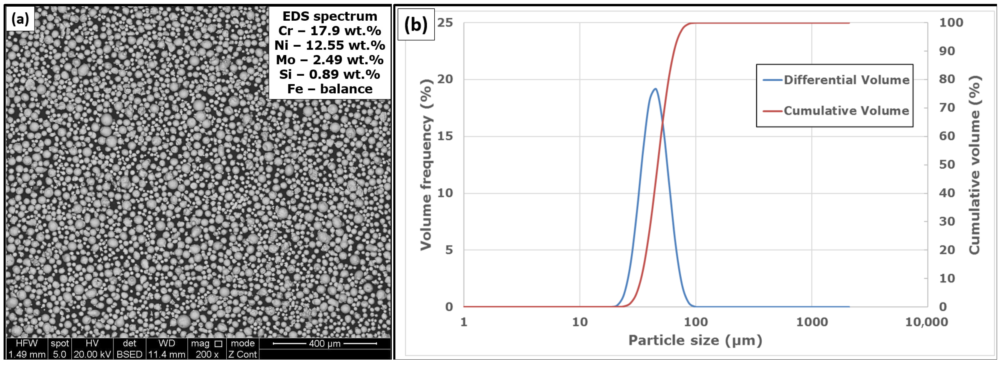
Austenitic stainless steel AISI 316L is a widely used material in AM due to its good machinability, high corrosion resistance, and toughness [10,11]. 316L SS has proven to be a suitable candidate for AM technologies, especially L-PBF, due to its chemical composition and microstructure, which yield a very fine microstructure with a high austenite content. This microstructure is the result of rapid melting and solidification during the process, which leads to a fine grain arrangement but also creates conditions for the formation of undesirable defects, such as porosity [12,13].
Porosity is one of the primary limitations that restrict the applicability of AM materials in demanding conditions. Even slight variations in porosity content, pore shape, or distribution can noticeably reduce tensile strength, ductility, and fatigue life. Experimental studies, therefore, increasingly aim to control these features through post-processing adjustments to improve specific mechanical responses [14,15]. Such processes are mainly thermal and thermomechanical processing, which are applied to the component after it is manufactured by the additive method in the so-called secondary processing [16].
Heat treatment serves to reduce internal stresses, promote chemical homogeneity, and initiate recrystallization. The final microstructure is strongly affected by the selected temperature, holding time, and cooling conditions [17,18]. At lower temperatures, some stress relaxation may occur without substantial changes in grain size, whereas higher temperatures can induce more pronounced recrystallization and grain growth. In all instances, modifications to porosity take place, which can be quantified using image analysis techniques [19,20].
Thermomechanical processing, such as rolling, is an effective tool for densifying materials, reducing pores, and influencing texture. Cold rolling is characterized by a higher degree of strain hardening (increased strength properties) [21,22,23,24]. In comparison, hot rolling allows a higher degree of plastic deformation with a lower risk of fracture (increased plastic properties) [25]. The combination of rolling with prior or subsequent annealing provides variability in modifying the microstructure and properties. The effect depends on many factors, including the processing temperature, the degree of deformation, the initial porosity, and other material properties affected by the L-PBF manufacturing process [26,27,28].
From a research perspective, it is important to understand the relationship between the type of thermomechanical processing, porosity parameters, and the resulting mechanical properties. Mechanical properties such as yield strength (YS), ultimate tensile strength (UTS), ductility (A), and hardness are essential for evaluating the suitability of components for real-world applications. In L-PBF fabricated parts, significant anisotropy of these properties can occur depending on the orientation of the sample relative to the growth direction [29,30]. Therefore, it is important to evaluate different directions: for example, along the Z axis, in the XY plane, and at an angle of 45°.
The mechanical properties of L-PBF processed AISI 316L SS vary significantly depending on the post-processing condition. In the as-built state, typical values include a YS of 480–580 MPa, UTS of 600–700 MPa, and elongation at a break between 25 and 35% [31]. After stress-relieving heat treatment (e.g., 650 °C/3 h), elongation can increase to ~40% with a slight reduction in strength while solution annealing at 1050–1100 °C followed by water quenching can reduce internal stresses, coarsen the microstructure, and increase ductility beyond 45% [17,32,33]. In contrast, cold rolling (up to 20%) can increase YS by 100–150 MPa due to strain hardening but often reduces ductility below 20% [21,34,35]. Hot rolling at 1050 °C allows for a balance of strength and ductility, with porosity levels reduced to <0.1% depending on the deformation level and cooling method [25].
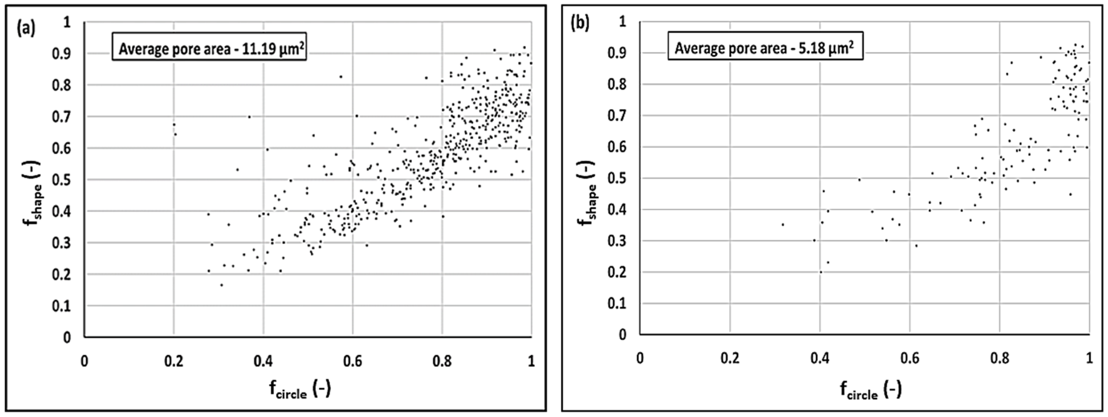
Quantitative porosity analysis involves measuring the volume fractions of pores and their dimensions, shape factors (e.g., circularity factor and shape factor), and aspect ratio [13,14,36,37,38]. These parameters can be extracted from microscopic images using digital image analysis, yielding a comprehensive view of the material’s internal structure. These measurements are crucial because various pore morphologies influence failure mechanisms in distinct ways. For instance, spherical pores are generally less detrimental to crack propagation compared to sharp-edged or elongated (ellipsoidal) pores [14,15,36,39]. Total volume porosity above 0.3–0.5% can represent a critical threshold for a sudden decrease in ductility, especially in applications subjected to cyclic loading [40]. Shape factors, such as the circularity factor, are important for predicting the probability of crack initiation—pores with lower circularity (sharp edges) have a higher fracture potential. The aspect ratio indicates the elongation of the pores and their orientation, which is important in the anisotropic behavior of the material [14].
Although numerous studies have investigated the effects of heat treatment on L-PBF 316L stainless steel [17,18,41,42,43], only a limited number have focused on the influence of plastic deformation, such as rolling [34,44,45], and even fewer have systematically analyzed the combined effects of thermomechanical processing parameters on porosity and mechanical properties [46,47]. Nevertheless, recent publications demonstrate a growing interest in the application of plastic deformation for improving the microstructural and mechanical integrity of L-PBF AISI 316L stainless steel [44,48,49].
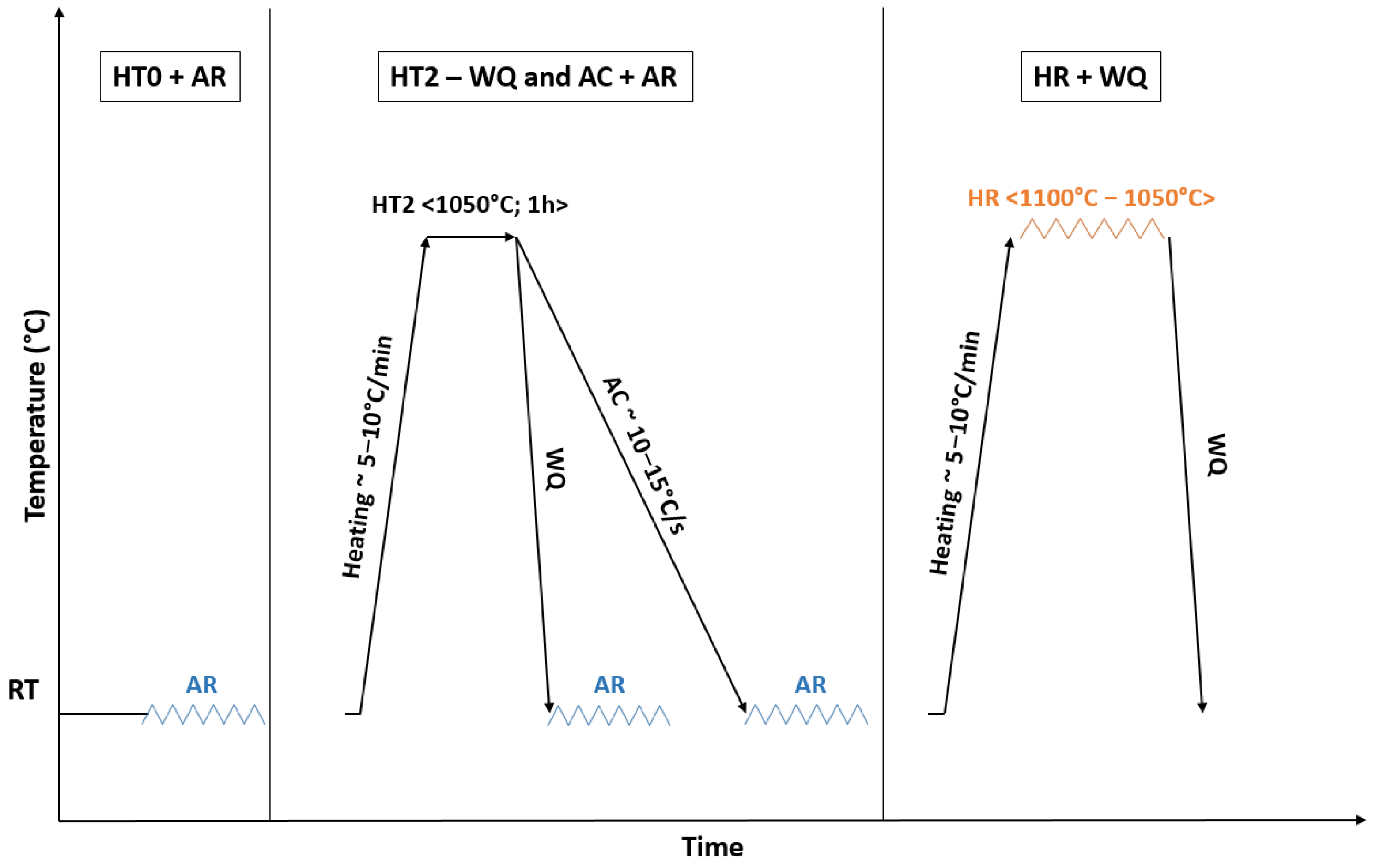
In this paper, we focus on a detailed analysis of the effect of several combinations of thermomechanical processes on the microstructure, porosity, and mechanical properties of AISI 316L stainless steel produced by the L-PBF method. We evaluate the effects of hot rolling at 1050–1100 °C followed by water quenching, as well as the effect of cold rolling applied before and after heat treatment. We pay special attention to the comparison of the conditions after annealing at 650 °C and 1050 °C, as well as the effect of air or water cooling. The aim is to identify the processing conditions that lead to optimal properties while minimizing defects.

2. Materials and Methods

2.1. Experimental Material and L-PBF Manufacturing Technology

The powder material used for manufacturing via the L-PBF process and for subsequent experimental testing was commercially procured as SS 316L-0407 (RENISHAW, Wotton-under-Edge, UK), with chemical composition listed in Table 1.
The particle size distribution and morphology of the supplied powder were analyzed using a Mastersizer 3000 analyzer (Malvern Panalytical Ltd., Malvern, UK) at the Technical University in Ostrava (Czech Republic), Center of 3D Printing–Protolab.
The particle morphology is illustrated in Figure 1a while the corresponding differential and cumulative particle size distributions are shown in Figure 1b. Additionally, a qualitative EDS analysis confirming the chemical composition of the powder is presented in Figure 1a. The dimensional characteristics of the powder are summarized in Table 2. Such characteristics are typical of gas-atomized powders intended for L-PBF, where controlled particle morphology and size distribution contribute to stable flowability, uniform layer deposition, and reproducible melting behavior.
Overall, the powder properties fall within the optimal range for the L-PBF process, ensuring consistent performance and microstructural homogeneity in the as-built condition.
All experimental samples were produced within a single manufacturing cycle to ensure the homogenization of properties across the entire set. Several sets of specimens were fabricated for different subsequent processing steps. One set of samples was prepared for post-processing by rolling to influence the material’s porosity. These samples were built in the vertical Z-orientation.
The specimens were produced using a Renishaw AM400 laser powder bed fusion system (Renishaw plc, Wotton-under-Edge, UK). The process parameters used during additive manufacturing are summarized in Table 3.
Additional sets of specimens were designated for uniaxial tensile testing and were machined to the required final dimensions. The tensile test samples were produced in three different build orientations: vertical (Z), diagonal (45°), and horizontal (XY). Each of these orientations was fabricated in three thermal conditions: in the as-built state without any heat treatment (HT0), after heat treatment at 650 °C for 3 h followed by air cooling (HT1), and after solution annealing at 1050 °C for 1 h followed by water quenching (HT2). The medium-temperature annealing at 650 °C for 3 h was selected based on literature and industrial practice as this condition effectively relieves residual stresses in L-PBF-produced 316L without causing significant grain growth or recrystallization [50,51,52].

2.2. Thermomechanical Processing

The thermomechanical processing routes applied to the different specimen sets are schematically illustrated in Figure 2. Four rolling strategies were implemented. The first set of specimens was ambient-rolled (AR) in the initial state without any prior heat treatment (HT0). The second and third sets were subjected to solution annealing at 1050 °C for 1 h (HT2), followed by either water quenching (WQ) or air cooling (AC, ≈10–15 °C/s), and subsequently AR. The fourth set was hot-rolled (HR). In this case, the material was preheated to 1100 °C to ensure a rolling temperature of 1050 °C. After hot deformation, the specimens were quenched in water (WQ). All rolling procedures were performed on an experimental DUO70 two-high rolling mill equipped with flat cylindrical rolls. The samples had initial dimensions of approximately 58 × 15.1 × 4 mm (length × width × thickness). The applied true plastic strain levels were ε = 10 15 20   % , corresponding to thickness reductions of 0.4 mm, 0.6 mm, and 0.8 mm, respectively. The deformation levels were achieved through one or more passes, depending on the prior processing condition of each specimen (e.g., as-built, solution-annealed), to account for differences in workability and mechanical response. Rolling was performed in a single direction. The applied deformation levels were selected to investigate the minimum degree of strain required to significantly reduce porosity originating from the additive manufacturing process. The maximum deformation level of 20% was chosen based on the observed porosity evolution.

2.3. Mechanical Testing and Microhardness

The static tensile tests were performed on all investigated conditions, including the as-built samples in three build orientations (Z, XY, and 45°), as well as AR and HR states. All tests were carried out at ambient temperature by the EN ISO 6892-1 standard [53] using a TINIUS OLSEN H300KU universal testing machine (Tinius Olsen, Horsham, PA, USA). The applied strain rate for all measurements was 0.00025 s−1. For each condition, a minimum of two tensile specimens were tested. From the tensile tests, the yield strength (YS), ultimate tensile strength (UTS), and elongation to fracture (A5) were evaluated.
Microhardness measurements were conducted using the Vickers method (HV1) on a Struers Duramin-5 hardness tester (Struers A/S, Ballerup, Denmark) by ISO 6507-1 standard [54]. For undeformed conditions, at least 20 indentations were made randomly across the sample surface. In the deformed states, the measurements were performed along three cross-sectional lines, with six indentations per line. The spacing between indentations exceeded 3.5 times the diagonal length of the impression, thus avoiding interference of plastic zones.

2.4. Evaluation of Porosity and Pore Morphology

The porosity and pore morphology were evaluated on metallographic cross-sections using optical microscopy combined with digital image analysis. The specimens were prepared by standard grinding and polishing procedures. Microstructural images were acquired in bright-field mode using a Zeiss Axiovert A1 optical microscope (Carl Zeiss Microscopy GmbH, Jena, Germany) at magnifications of 50× and 100×.
Image analysis was performed using the open-source software ImageJ (Version 1.54g, National Institutes of Health, Bethesda, MD, USA). For each processing condition, multiple fields of view were analyzed to ensure statistical relevance. The total porosity was calculated as the area fraction of dark (non-reflective) regions relative to the total analyzed area. In addition to porosity content, pore morphology was characterized using several shape descriptors. The aspect ratio (AsR) was defined as the ratio of the major to minor axis of an ellipse fitted to each pore. Circularity f c i r c l e was calculated as follows [14,55]:
f c i r c l e = 4 π A P 2  
Here, A is the pore area and P is the perimeter, with values approaching 1 indicating near-circular pores. The shape factor f s h a p e was calculated thus:
f s h a p e = D m i n D m a x  
Here, D m i n and D m a x are the minimum and maximum Feret diameters of the pore, respectively. This parameter describes the elongation of the pores, with values close to 1 indicating equiaxed pores and lower values corresponding to elongated or irregular shapes. These parameters were used to compare the evolution of porosity and pore geometry between different thermomechanical processing states, build orientations (Z, XY, 45°), and heat treatments.

2.5. Microstructure, Fractography and XRD Measure

Metallographic preparation was performed using a standard procedure, which included successive grinding, followed by polishing with diamond suspensions down to a particle size of 1 µm. The samples were subsequently etched with Glyceregia etchant, with the etching time adjusted to the specific state of the material processing to achieve optimal contrast of the microstructures. Microstructure observation was performed using a Zeiss Axiovert A1 optical microscope (Carl Zeiss AG, Oberkochen, Germany). Fractographic analysis was performed on fracture surfaces after tensile tests. A JEOL JSM-7000F scanning electron microscope (JEOL Ltd., Tokyo, Japan) was used to observe the fracture morphology. Energy-dispersive X-ray spectroscopy (EDS) using an Oxford Instruments INCA X-sight model 7557 system (Oxford Instruments, Oxford, UK) was also used to identify and characterize the phases present on the fracture surfaces.
X-ray powder diffraction (XRD) was utilized for phase analysis of the prepared materials. A Philips X’Pert Pro diffractometer (Philips, Amsterdam, The Netherlands) equipped with a Co anode X-ray tube (Kα1 = 1.78897 Å and Kα2 = 1.79285 Å) was employed. Diffractograms were collected over a 10–140° 2θ range at ambient temperature. Each measurement was conducted in Bragg–Brentano (reflection) geometry with a step size of 0.03° and a counting time of 60 s per step.
Rietveld refinement of the XRD data for lattice parameter determination was performed using GSAS-II software (Argonne National Laboratory, Lemont, IL, USA; Version 5636).

3. Results

3.1. Mechanical Properties

In the initial as-built condition (HT0), the material exhibited high strength (YS up to 605 MPa) while maintaining relatively good ductility, especially in the XY orientation (A5 = 38.2%, see Table 4). However, samples oriented in the Z direction consistently showed the lowest elongation (A5 = 21.4%), indicating pronounced anisotropy resulting from the layer-wise nature of the L-PBF process. The HT1 condition led to a partial reduction in strength, particularly in the XY direction, while other orientations showed only minor changes. A slight improvement in ductility was observed in some cases, which could be attributed to stress relief and microstructural recovery. The HT2 condition caused the most significant drop in strength properties but simultaneously led to a substantial increase in ductility in the XY and 45° orientations (A5 = 46.6% and 43.8%, respectively). This improvement suggests effective microstructural homogenization and a reduction of internal defects.
In all tested cases, the samples built in the Z direction showed the lowest elongation. This can be attributed to higher porosity aligned with the build axis, where pores serve as starting points for cracks and reduce the material’s plastic deformability. For this reason, the Z-oriented condition was selected as the baseline for subsequent thermomechanical processing, aiming to suppress the detrimental effect of porosity and enhance ductility in this critical orientation.
Representative stress–strain curves for the as-built, heat-treated, and thermomechanically processed conditions are shown in Figure 3, illustrating the influence of heat treatment and plastic deformation on mechanical properties.
The mechanical properties presented in Table 5 were evaluated exclusively for specimens produced in the vertical (Z) orientation. This direction is known to accumulate the highest concentration of manufacturing defects typical for the L-PBF process, such as lack-of-fusion porosity or weak interlayer bonding, making it the most critical in terms of mechanical performance. For this reason, the Z-orientation was selected for thermomechanical processing to investigate the potential of post-processing (rolling and heat treatment) to reduce the negative impact of such defects and improve both ductility and strength.
In the condition without prior heat treatment (IS–HT0–AR), AR led to a gradual increase in strength and hardness with increasing deformation. At 20% deformation, a yield strength of 550 MPa was achieved, but with a relatively low ductility (A5 = 6.5%).
To improve this condition, solution annealing (HT2) was applied before rolling, followed by two different cooling strategies: air cooling and water quenching. Better results were achieved in the HT2 + WQ–AR condition, where at 20% deformation, the sample reached YS = 584 MPa, UTS = 835 MPa, and A5 = 14.7%. This approach led to the softening of the matrix, allowing internal pores to deform more plastically, thereby reducing the detrimental effect of porosity in this state. The condition after HR, followed by immediate water quenching, exhibited different behavior. Although the strength was lower (YS = 253–370 MPa), the ductility improved significantly (A5 = 29.3–40.6%), especially at lower degrees of deformation. The mechanical properties obtained in this study, particularly for the HR + WQ condition, aligned well with values reported in the literature for L-PBF 316L stainless steel. Typical UTS values for as-built or heat-treated conditions range between 550 and 650 MPa, and for elongation, between 25 and 45% [56,57,58]. Moreover, recent studies focusing on post-processing via plastic deformation have shown that such treatments can further enhance ductility and homogenize the mechanical response [21,44,48]. This indicates that the investigated thermomechanical processing strategies are effective in achieving bulk-like density and consistent mechanical performance.
The HV1 microhardness results presented in Figure 4a correspond to AISI 316L SS samples without plastic deformation, evaluated in different heat treatment conditions and three build orientations (45°, Z, and XY). The data demonstrate that the degree of heat treatment is the dominant factor influencing hardness. The average hardness in the as-built state (HT0) was approximately 229.8 HV1, which decreased to 203.7 HV1 after the HT1 condition and further to 191.4 HV1 after solution annealing. This decrease reflects microstructural recovery, stress relief, and grain growth due to increased thermal exposure. The differences between the build orientations were relatively small. For example, in the HT0 state, the highest hardness in the XY direction (229.8 HV1) differed from the lowest value in the Z direction (222.4 HV1). Similar minor variations were observed in other heat-treated conditions, suggesting that build orientation does not have a significant influence on the microhardness of the material.
The HV1 microhardness results shown in Figure 4b correspond to Z-oriented samples after various thermomechanical processing conditions, including ambient and HR, with plastic deformation levels of 10%, 15%, and 20%. In all conditions, hardness increased with higher deformation, reflecting the typical effect of strain hardening. The highest hardness (309.6 HV1) was obtained in the AR state without prior heat treatment at 20% deformation. Samples that were solution-annealed before rolling (HT2 + AR) showed only a slight reduction in hardness compared to the non-annealed condition, suggesting that although the structure was recrystallized, strain hardening from cold deformation remained the dominant strengthening mechanism. The lowest hardness values were observed in the HR and quenched condition (HR + WQ), where hardness was less sensitive to the degree of deformation and ranged between 185.9 and 205.7 HV1, indicating the influence of recovery processes during high-temperature deformation.

3.2. Porosity and Pore Morphology

Porosity and pore morphology were quantitatively evaluated using binarized optical micrographs obtained from polished cross-sections. Representative images for selected states are shown in Figure 5. The analyzed images were converted to black-and-white (binary) format to distinguish pores (black regions) from the matrix (white background). This conversion was performed to enable accurate image analysis in ImageJ and determine parameters such as total porosity, pore shape (via circularity f c i r c l e ), and elongation (via shape factor f s h a p e ). Figure 5 compares three selected processing conditions in the Z-direction: the (a) as-built condition (HT0) without deformation, (b) solution-annealed condition (HT2) without deformation, and (c) HR state after HT2. In the as-built condition (a), a high volume fraction of small, irregular pores was visible. After solution annealing (b), fewer but larger and more irregular pores remained, indicating partial pore growth and coalescence. In contrast, the HR condition (c) exhibited a significantly reduced number and size of pores, suggesting effective pore closure and densification due to deformation at elevated temperatures.
The quantitative analysis of porosity and pore morphology across different processing states is summarized in Table 6 and Table 7. In the undeformed samples, porosity was observed to increase with the severity of heat treatment. The lowest porosity values were found in the as-built condition (HT0), ranging from 0.2% in the XY orientation to 0.3% in the Z-direction. After heat treatment at 650 °C (HT1), porosity increased moderately across all orientations, with a maximum of 0.59% in the Z-direction. The solution-annealed state at 1050 °C (HT2) exhibited the highest porosity levels, reaching 0.86% in the Z-direction, which was likely associated with pore growth and coalescence during prolonged high-temperature exposure.
Morphological descriptors further substantiated this trend. The circularity ( f c i r c l e ) increased slightly with increasing thermal severity, with values in the Z-direction ranging from 0.76 (HT0) to 0.8 (HT2). The shape factor ( f s h a p e ) and AsR highlighted increasing elongation and irregularity of pores, with a maximum AsR of 2.42 observed for the HT1–Z condition.
In contrast, samples subjected to thermomechanical processing demonstrated a consistent reduction in porosity with increasing deformation. In all rolled conditions, porosity dropped significantly—from initial values of 0.21–0.25% at 10% deformation to as low as 0.05–0.12% at 20%. The lowest porosity was achieved in the HR + WQ state at 20% deformation (0.05%), confirming the efficiency of HR in mitigating residual porosity. This reduction is attributed to the collapse or redistribution of pores under compressive strain, particularly when combined with prior solution annealing.
Morphological parameters were also improved by deformation. Circularity ( f c i r c l e ) increased progressively with strain, reaching 0.90 in the HR + WQ −20% sample, indicating more equiaxed pore geometries. Likewise, f s h a p e rose to 0.72 while the AsR dropped to 1.57, suggesting a transition toward more isotropic and less elongated pores. These changes confirm that thermomechanical treatment not only suppresses porosity but also contributes to the homogenization of pore geometry.
Overall, the results underscore the effectiveness of thermomechanical processing—especially HR combined with prior annealing (HR + WQ)—in reducing porosity and refining pore morphology. This state exhibited the lowest porosity and the most regular, near-spherical pore geometry among all examined conditions, highlighting its suitability for demanding structural applications.
The IS–HT0 condition represents the undeformed as-built state of the material, prior to any thermomechanical processing. In the IS–HT0 condition (Figure 6a), the values exhibited a broad distribution, with f c i r c l e ranging from below 0.3 to nearly 1.0 and f s h a p e spanning from approximately 0.2 to 0.8. This dispersion indicated a high degree of morphological variability, including the presence of numerous irregular and elongated pores. Although a general correlation between f c i r c l e and f s h a p e was noticeable, the scattered values suggested a heterogeneous and anisotropic microstructure, typical of as-built states with unrefined solidification defects. The average pore area reached 11.19 µm2, reflecting a higher pore content and a lack of morphological uniformity.
In contrast, the HR + WQ condition (Figure 6b) revealed a more compact cluster of data points concentrated in the upper right portion of the plot. Most pores exhibited values of f c i r c l e > 0.8 and f s h a p e > 0.6, indicating a predominance of rounded and isotropic pores. The average pore area decreased to 5.18 µm2, demonstrating the effectiveness of combined thermal and mechanical processing in reducing pore size and improving morphological uniformity. The reduced dispersion in this sample confirms the homogenizing effect of hot deformation following solution annealing. These results emphasize the strong correlation between the circularity and shape regularity of pores and clearly show that only thermomechanical treatment can achieve a substantial reduction in the number of pore defects while improving the isotropy and consistency of pore morphology.

3.3. Microstructure

Figure 7 shows the microstructural evolution of AISI 316L stainless steel produced by L-PBF, analyzed in the Z-direction under various heat treatment conditions.
Figure 4a illustrates the as-built (HT0) condition. The typical L-PBF melt pool structure is visible, with overlapping curved melt pool boundaries. Inside the melt pools, a fine cellular and columnar subgrain morphology was developed due to rapid solidification. Spherical gas pores were also present, distributed along melt pool edges. No signs of recovery or recrystallization were evident, and the structure retained its original laser-induced texture. Figure 7b shows the HT1 condition after annealing at 650 °C for 3 h. Melt pool boundaries were still visible but partially fragmented. Localized grain growth and subgrain coalescence were observed, especially along pool boundaries, indicating the onset of thermally activated microstructural transformation. However, large regions still preserved the typical L-PBF morphology. Figure 7c corresponds to the HT2 condition (1050 °C/1 h + WQ), where complete recrystallization occurred. Melt pool morphology was no longer recognizable. The microstructure consisted of equiaxed grains with significant grain size heterogeneity. Occasional annealing twins confirmed high-temperature recrystallization and diffusion. Figure 7d highlights a defective region also found in the HT2 condition. A lack-of-fusion defect was observed, surrounded by unmelted particles and an irregular inclusion. A crack propagated from this region, suggesting that local inhomogeneities in the as-built structure can lead to crack formation during thermal exposure. It remains unclear whether the crack nucleated during heat treatment or was already initiated during L-PBF. Figure 7e shows another melt pool from the HT1 condition. Well-defined cellular and columnar subgrain structures were visible within the pool, consistent with high thermal gradients and directional solidification. The central boundary between adjacent melt tracks may also have contributed to structural weakness if porosity or incomplete fusion was present. These micrographs illustrate the progressive transformation of the L-PBF structure under increasing thermal exposure—from preserved melt pools and subgrains in HT0 through partial transformation in HT1 to complete recrystallization in HT2. Additionally, residual manufacturing defects, such as unmelted particles or lack of fusion, remained critical weak points, which thermal treatments could potentially exacerbate.
The microstructural evolution of L-PBF-produced AISI 316L stainless steel subjected to various rolling conditions is presented in Figure 8. The micrographs illustrate the effect of 20% deformation applied via ambient or HR treatment after different thermal preprocessing (HT0, HT1, HT2).
As shown in Figure 8a, the as-built HT0 sample AR by ε = 20% retained characteristic melt pool boundaries and both columnar and cellular subgrains. While there were slight signs of structural distortion, there was no strong indication of pronounced elongation in the rolling direction (RD). The porosity, however, was notably reduced: fewer pores were observed, many had a more spherical shape, and the occurrence of sharp or crack-like pores was significantly diminished. Figure 8b shows the microstructure of the HT1 condition after 20% AR. Small newly formed grains were visible within the deformed matrix, suggesting the onset of strain-induced recrystallization. However, the recrystallized areas were limited, and the overall microstructure remained dominated by plastic deformation. Figure 8c highlights a pore with an associated microcrack propagating into the matrix. This image exemplifies how remnant porosity can act as a crack initiation site during deformation, particularly in materials that are only partially stress-relieved. This is a known concern in L-PBF materials due to their inherent porosity. As shown in Figure 8d, the fully annealed HT2 sample exhibited clear deformation bands after 20% AR. These bands appeared in various orientations—not exclusively aligned with RD—indicating multi-directional plastic strain accommodation in a homogenized matrix free of L-PBF substructure. Figure 8e presents the HR condition with ε = 20% deformation at 1050–1100 °C followed by water quenching. The microstructure was strongly heterogeneous in grain size, ranging from highly elongated to nearly equiaxed grains. While annealing twins were observed, their number was relatively low. The fragmented grains and irregular grain boundaries indicate that partial dynamic recrystallization occurred during high-temperature straining, resulting in a complex, bimodal structure.
X-ray diffraction (XRD) analysis was performed on samples in the as-built condition without heat treatment (IS) and after 20% AR (E20), both corresponding to the HT0 condition. The diffractograms shown in Figure 9 confirm the presence of a face-centered cubic (fcc) austenitic phase in both conditions. No secondary peaks indicative of deformation-induced martensite were detected, suggesting that the austenitic matrix remained stable even after 20% plastic deformation.
A comparison of the two conditions revealed only minor differences. A slight shift of diffraction peaks toward lower 2θ values was observed, particularly for the (111) reflection. This shift corresponded to an increase in the lattice parameter from 3.6001 Å in the IS state to 3.6004 Å in the deformed E20 sample. Although this change was subtle, it may have qualitatively reflected slight lattice distortions or increased defect density. However, we note that such small differences are near the resolution limits of laboratory XRD, and direct characterization methods such as TEM would be required to confirm and quantify these effects.

3.4. Fractography

The fractographic analysis of fracture surfaces after the tensile testing of undeformed conditions is shown in Figure 10. The results reveal significant differences in fracture mechanisms and defect types depending on the applied heat treatment.
In the as-built condition (HT0), the fracture surface exhibited a predominantly brittle character (Figure 10a), with cleavage facets indicating a mixed-mode fracture mechanism. Numerous small spherical pores were distributed across the surface, likely originating from gas entrapment. These features served as sites for crack initiation. The minimal presence of ductile features (e.g., dimples) was attributed to high residual stresses and porosity typical of the L-PBF process. Figure 10b shows clusters of unmelted powder particles on the fracture surface. These spherical particles indicate insufficient melting during production and point to a localized failure in laser energy transfer. Such features act as stress concentrators and contribute to crack initiation. Figure 10c captures a prominent cleavage facet along with a spherical oxide inclusion (confirmed by EDS analysis in Table 8). A secondary crack emanating from the inclusion suggested that such non-metallic defects can significantly promote crack initiation and propagation, reinforcing the brittle fracture behavior of the HT0 condition.
For the HT1 condition (Figure 10d), the fracture morphology was more complex. Several smaller pores appeared to have coalesced into larger cavities, indicating pore growth during annealing. The overall fracture behavior remained predominantly brittle.
In the case of the HT2 condition, a pronounced lack-of-fusion defect with adjacent unmelted particles was observed at the specimen’s edge, serving as a crack initiation site. EDS analysis confirmed these to be remnants of the original powder rather than inclusions. Despite the high-temperature treatment, the HT2 condition still showed a local occurrence of cleavage facets and unmelted particles. However, the fracture surface revealed smoother transitions and a greater presence of ductile features (e.g., shallow dimples), suggesting that recrystallization contributed to stress relaxation.
Overall, a progression could be observed from sharp, well-defined pores and predominantly brittle fracture in the HT0 condition toward slightly improved fracture ductility, changes in pore morphology, and a noticeable increase in pore surface area after heat treatment. Nevertheless, defects such as unmelted particles and lack-of-fusion regions remained dominant factors influencing fracture behavior across all investigated conditions.
Figure 11 presents SEM micrographs of fracture surfaces of samples subjected to various combinations of plastic deformation and heat treatment. The sample shown in Figure 11a exhibited only minimal ductile fracture features localized in small regions. A dimple-like morphology predominantly characterized the fracture surface while the occurrence of residual pores was significantly reduced compared to the as-built condition. In Figure 11b, deformed spherical powder particles are visible, which were remnants of the manufacturing process in areas with a lack of fusion. Their presence could locally reduce the ductility of the material. Figure 11c demonstrates the effect of plastic deformation through the appearance of pronounced deformation bands that transition into microcracks, indicating stress localization and potential crack initiation sites. In the rolled conditions, small clusters of oxide inclusions were also observed. EDS analysis in Table 8 (Spectrum 6) confirms the presence of oxide-based particles. These inclusions likely originated during the L-PBF process or as contamination from the powder feedstock and may have acted as fracture initiation points.
Hot rolling significantly altered the fracture behavior of the material under tensile loading. The fracture surface exhibited a ductile character, characterized by well-developed dimples. The observed pores were smaller, mostly spherical, and uniformly distributed throughout the matrix. In addition, flow lines typical for hot-deformed material are evident in Figure 11f, indicating substantial plastic deformation and improved microstructural homogeneity.

4. Discussion

Experimental results indicate that heat treatment alone (HT0 to HT2) increased porosity in the Z-axis from 0.30% to 0.86%, likely due to pore growth associated with thermal relaxation and reduced dislocation density. During heat treatment, lattice reconfiguration and diffusion processes occur, which can lead to the coalescence of small pores and their subsequent growth, especially if enclosed gases are present in the material. This phenomenon is particularly pronounced at higher temperatures when atomic diffusion and grain boundary mobility enable the reshaping of pores. At the same time, microcracks or pores that were originally “pressed” into the matrix by residual stresses or deformation may open, which is consistent with the findings in the work [32,36]. On the other hand, as also reported by studies [17,59,60], thermal exposure can also lead to a decrease in porosity due to improved diffusion and sintering processes that contribute to the closure and more rounded shape of pores, especially at longer annealing times and lower initial porosity. The differences in the observed trends can thus be explained by both the type of pores (closed vs. interconnected, gas vs. shrinking) and their size and distribution, as well as by different behaviors at varying temperatures and atmospheres (e.g., vacuum, inert gas, air). In our case, the mechanisms of growth of existing gas pores and relaxation of the internal structure were likely to prevail, leading to a slight increase in their size or volume fraction. It is also important to consider that the apparent rise in porosity can also be influenced by the increased detectability of pores after a change in their morphology—e.g., after rounding or the widening of originally sharply defined defects. A similar trend was also noted by Deng et al. [61], who observed the complete recrystallization of AM 316L SS after annealing at 1065 °C and 1150 °C, which led to grain growth and changes in the microstructure.
The tendency of pores to round at higher temperatures may be a consequence of the activation of diffusion processes and the simultaneous reduction of dislocation density during heat treatment. It should be noted that this observed reduction in dislocation density is interpreted qualitatively, based on microstructural recovery and grain growth. A quantitative assessment (e.g., using EBSD-KAM analysis or TEM) was not performed in this study but could provide additional insight in future work. At elevated temperatures, atomic mobility increases, which allows the surface and volume diffusion of the material towards minimizing the surface energy. Irregular and elongated pores have a higher surface energy than rounded ones. Therefore, they naturally transform into more spherical shapes, which are thermodynamically more favorable. At the same time, internal stresses relax due to the recovery and reduction of dislocation density, which further facilitates the reorganization of the local microstructure and the movement of grain boundaries [14,41,62,63]. The combination of these mechanisms leads to the observed improvements in pore morphological parameters, such as an increase in sphericity (e.g., f c i r c l e from 0.76 to 0.9) and a decrease in elongation (AsR from 2.07 to 1.65).
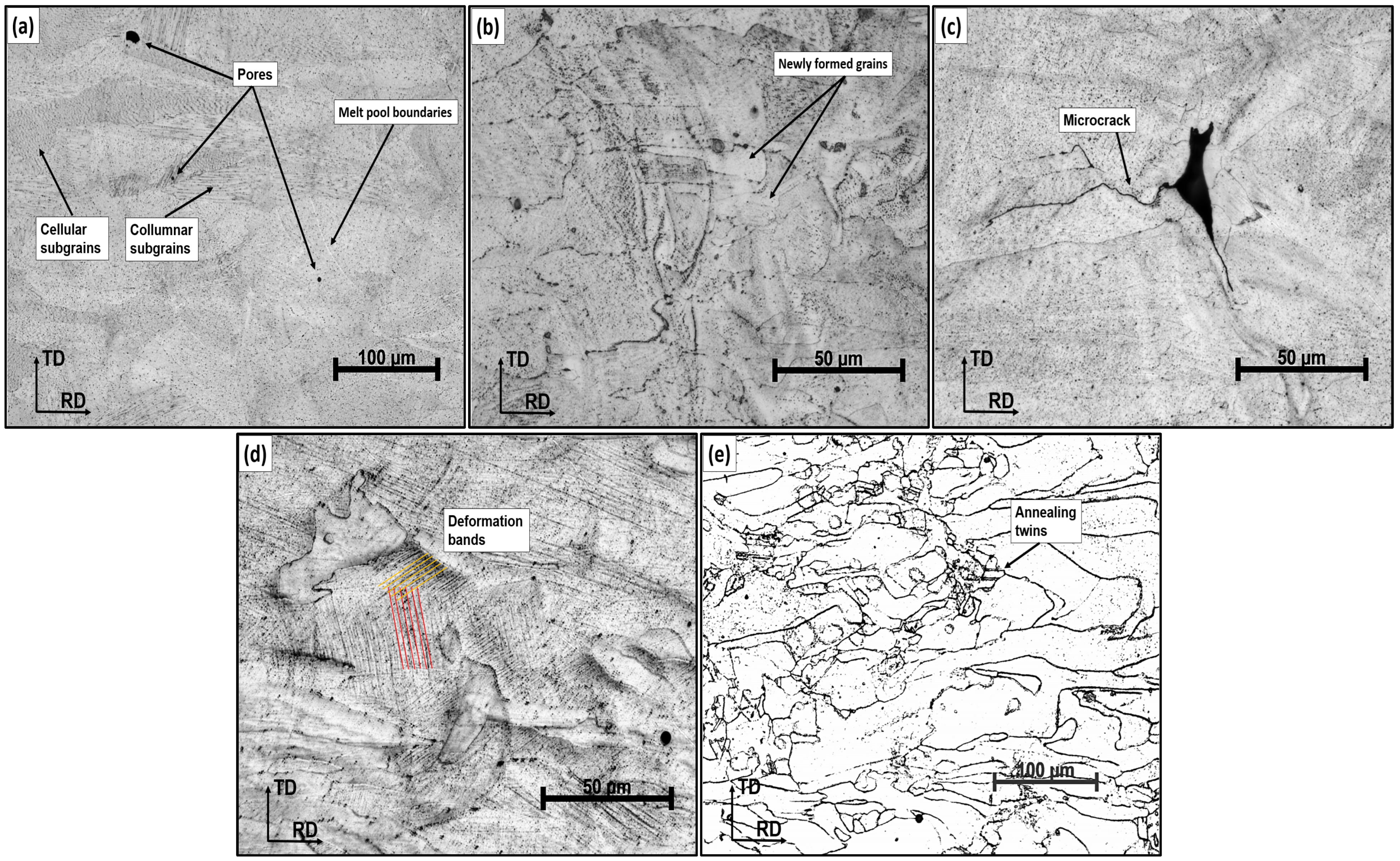
In the case of the material produced by the L-PBF method, the initial state (HT0) is characterized by a fine-grained substructure and a high dislocation density due to the rapid melting and solidification of the layers. After recrystallization annealing at 1050 °C (HT2), the original fine cellular structure dissolves, and grain growth occurs, the rate of which depends on the cooling method. Slow cooling in the air (AC) allows grain growth to continue during cooling, resulting in a coarser and softer microstructure with a low dislocation density. Conversely, rapid cooling in water (WQ) effectively stops grain growth and preserves a finer recrystallized structure in which residual stresses and a higher defect density remain. Therefore, subsequent plastic processing is significantly more effective in this state, leading to enhanced pore compaction and improvements in both strength and ductility.
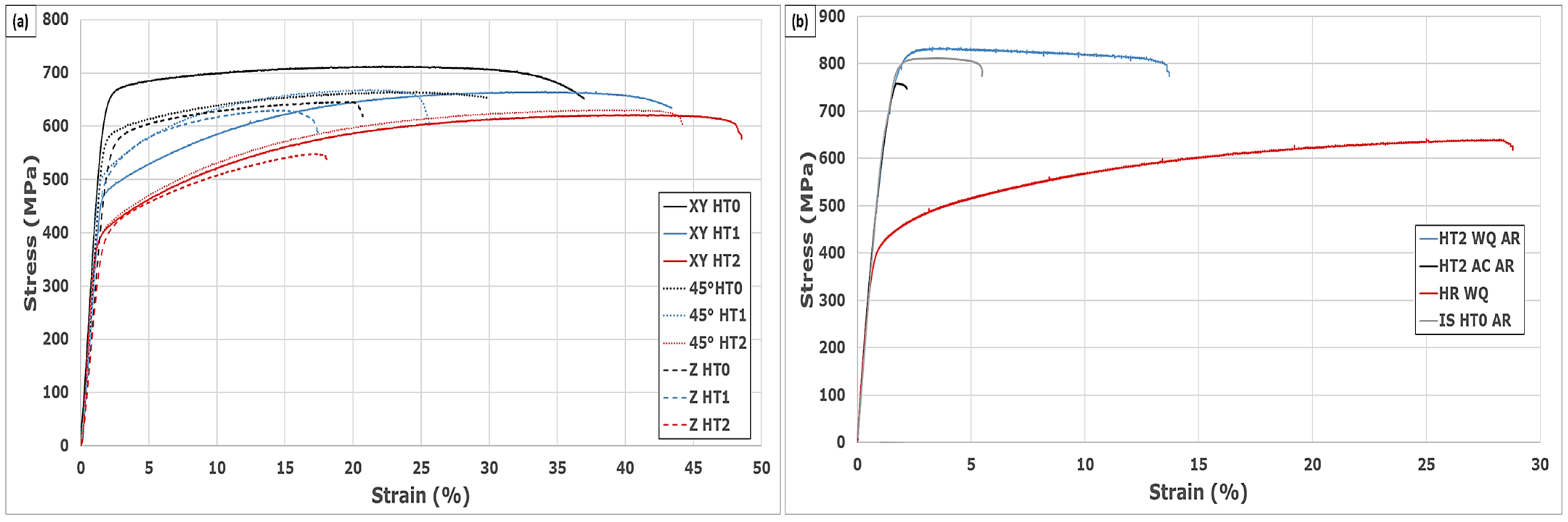
The HT2 + WQ condition brought the most significant changes. After ambient rolling with 20% deformation, the porosity decreased to 0.05%, which was the lowest value among all the conditions examined. At the same time, the sphericity of the pores improved ( f c i r c l e = 0.87), and their elongation decreased (AsR = 1.64), which indicates a favorable change in the morphology of the defects. The combination of recrystallization annealing at 1050 °C and subsequent plastic deformation had a synergistic effect, resulting in minimized porosity, improved pore morphology, and a balanced combination of high strength (UTS ≈ 835 MPa) and moderate ductility (A5 ≈ 14.7%). This result was in accordance with the study by Kan et al. [64], where it was confirmed that a suitably selected deformation leads to a reduction in the number of fracture initiators and the homogenization of the stress field in the microstructure.
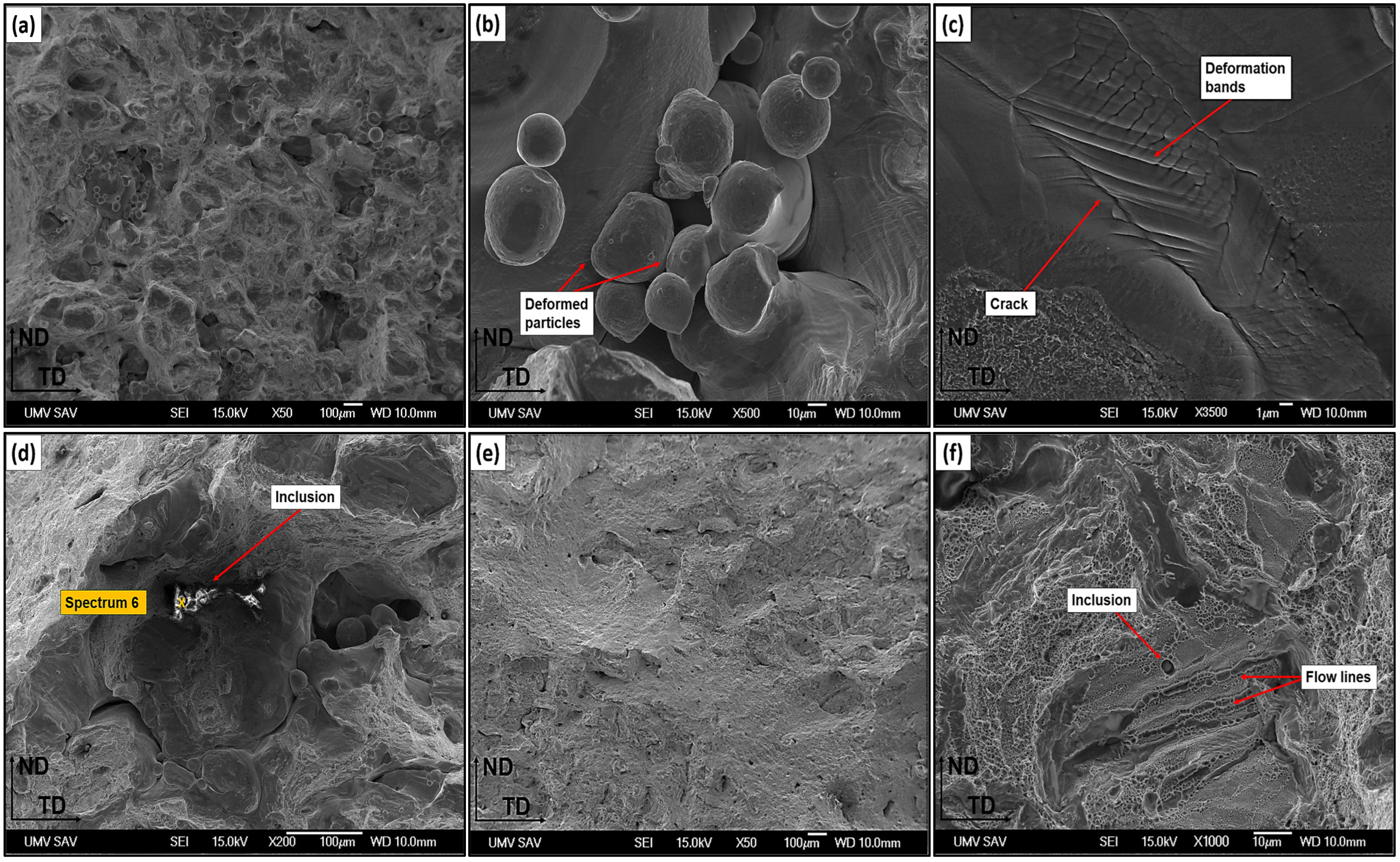
Significant changes were also observed in the HR + WQ condition, where hot deformation was applied, followed by rapid cooling in water. The HR + WQ condition revealed microstructural features indicative of dynamic recovery and partial recrystallization. Optical microscopy revealed evidence of subgrain formation and deformation bands aligned with the rolling direction, characteristic of hot working at elevated temperatures. These features suggest that recovery processes dominated during hot deformation, resulting in the rearrangement and annihilation of dislocations. In some regions, newly formed recrystallized grains were observed, supporting the occurrence of dynamic recrystallization during rolling. This microstructural evolution facilitated pore closure and improved morphological uniformity, as well as contributed to the observed reduction in hardness and enhancement of ductility. Already at 10% deformation, the porosity reduced to 0.20% and at 20% to 0.05% while the value also decreased significantly (from 1.86 to 1.57). This condition also showed the best morphological parameters of the pores ( f c i r c l e up to 0.90). There was a noticeable softening of the matrix due to the influence of high temperature, which facilitated the closure of the pores during rolling. Similar results were also reported in a study from [65], where high-temperature deformation combined with rapid cooling significantly eliminated interporous stress concentrators. These results demonstrate the gradual improvement of pore morphology, especially in terms of increased sphericity and reduced shape irregularity, which correlated with the observed reduction in total porosity. 
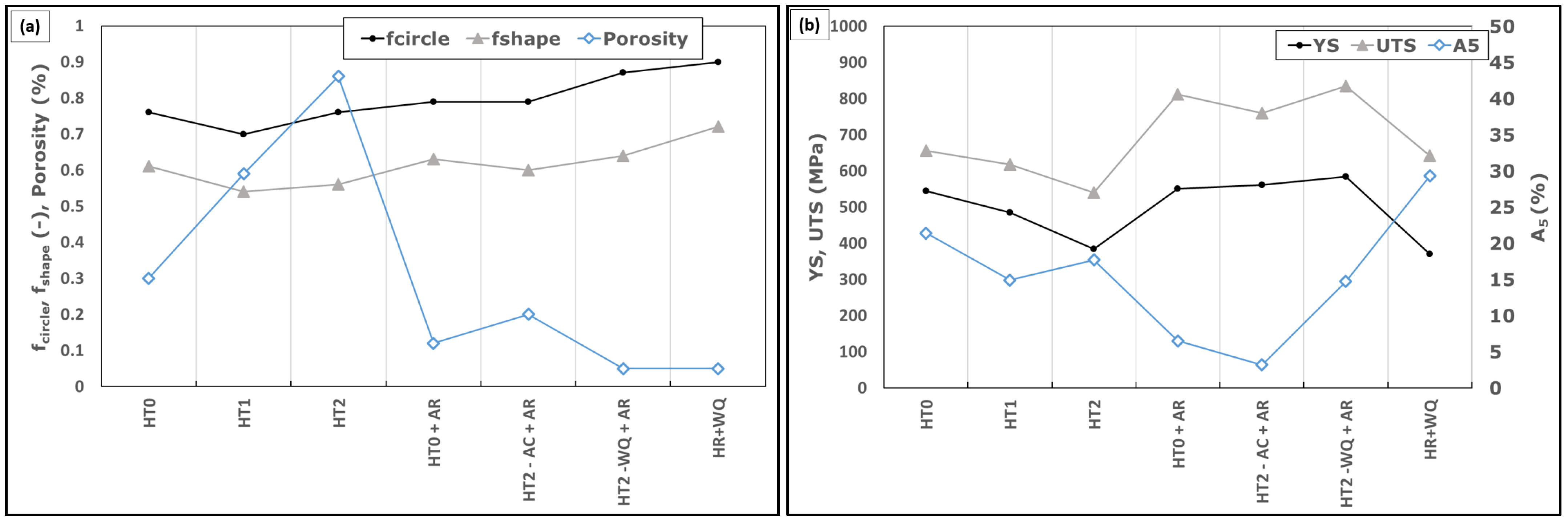
Figure 12a provides a comparison of f c i r c l e , f s h a p e , and porosity across all processing states, highlighting the advantage of combined thermal and mechanical treatment (HT2 − WQ + AR, HR + WQ).
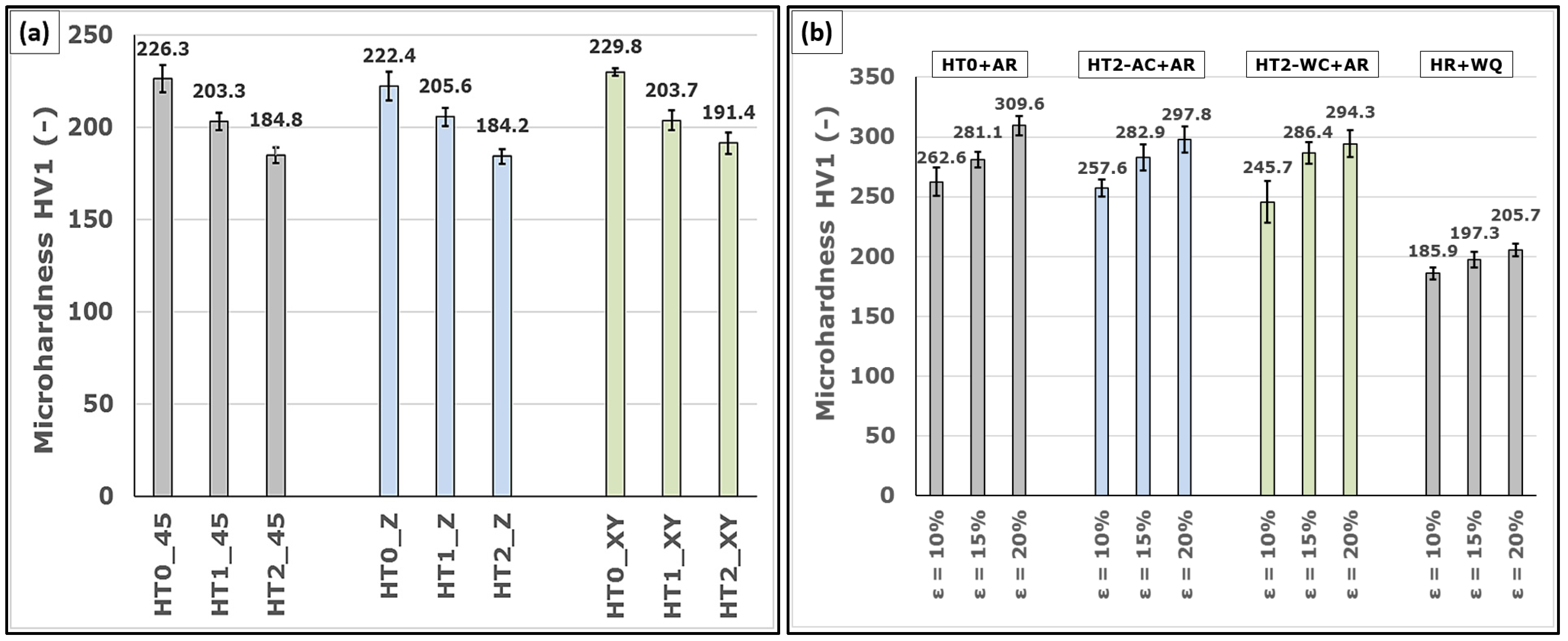
In terms of microhardness, the highest values were observed in the HT0 state (240–250 HV1), while subsequent treatments, especially HT2 and HR + WQ, led to a decrease to below 200 HV1. This decrease was a likely consequence of recrystallization and a reduction in dislocation density. However, in combination with rolling (HT2 + WQ), a particular strength of the matrix was restored due to strain hardening. Overall, it can be stated that heat treatment itself (especially HT2) leads to pore growth, but at the same time, it improves pores’ morphological properties. Subsequent rolling, especially in combination with HT2 + WQ or HR + WQ, can significantly reduce porosity, improve pore morphology, and bring a comprehensive improvement in mechanical properties. This is reflected in the mechanical properties shown in Figure 12b, where YS, UTS, and elongation (A5) are compared. The HT2 − WQ + AR and HR + WQ states achieved the best balance of strength and ductility, confirming the effectiveness of thermomechanical processing. These approaches represent an effective way to eliminate the negative impact of L-PBF porosity on the properties of final products by including secondary processing.
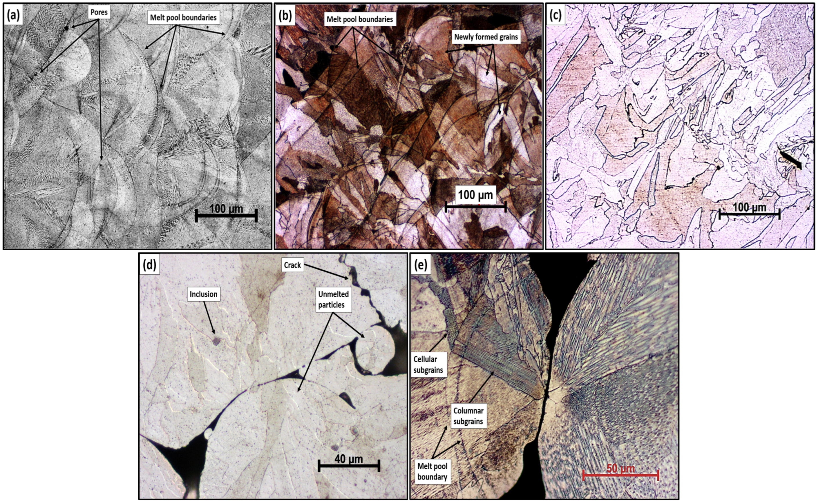
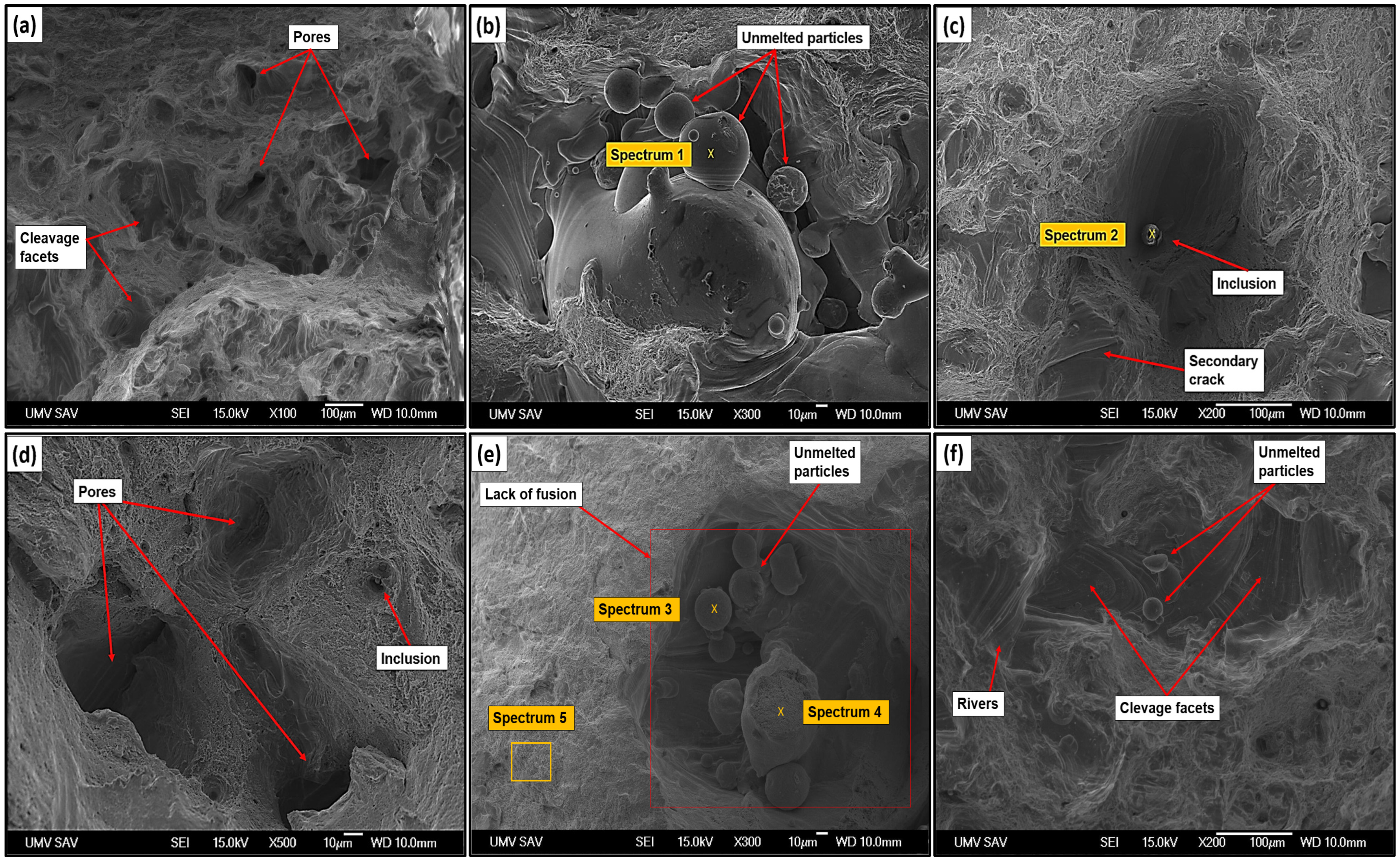
Fractographic analysis showed significant differences in fracture mechanisms between the conditions. In the HT0 condition, brittle fracture through cleavage facets dominated, accompanied by the presence of numerous pores and unfused particles. The HT1 condition showed an increase in cavities, but the fracture remained brittle. It was not until the HT2 condition that signs of ductile fracture (dimples) appeared, which was an indicator of relaxation and structural transformation. Similarly, authors Liebsch et al. [66] report that the onset of dimple fracture can only be expected when annealing above 1000 °C.
The lack of fusion defects was also observed after high-temperature annealing, specifically in the HT2 state (Figure 10e). These regions arose as a result of insufficient fusion between adjacent traces or layers during the L-PBF process, leading to sharp interlayer interfaces without metallurgical bonding. EDS analyses (spectrum 5) confirmed that these locations contained remnants of the original powder, not oxide inclusions, which emphasizes that this was a manufacturing issue related to printing parameters (e.g., low laser energy or inappropriate hatch distance). These defects had a high AsR and sharp edges, which made them effective stress concentrators and, therefore, often become initiation sites for cracks, as confirmed by fractographic analysis. In terms of pore morphology, it can be seen that samples with the occurrence of lack-of-fusion defects (e.g., HT0 and HT2) showed the highest aspect ratio (AsR > 2.2), which correlated with an increased susceptibility to brittle fracture. Although the overall porosity increased after HT2, the sphericity of the pores improved, and the presence of large, sharply defined defects remained crucial for the initiation of fracture. A similar influence of these defects was also confirmed by Popovich et al. [67], who showed that lack-of-fusion pores dominate in determining ductility. In contrast, gas pores have a more negligible effect on premature failure. In addition, oxide inclusions were also observed in some areas (Figure 8c), indicating powder contamination or oxygen absorption during printing. These non-metallic phases acted as initiation points for secondary cracks. EDS analysis (spectrum 2) revealed elevated levels of O, Si, and Cr, suggesting the co-presence of silica and spinel-type oxides, such as MnCr2O4. These hard, brittle particles contribute to the local disruption of plastic deformation and promote intercrystalline fracture. Thus, fractography reveals that the combination of highly porous regions, lack-of-fusion defects, and inclusions constitutes a set of critical sites responsible for crack initiation and ductility loss.

5. Conclusions

Based on the conducted experiments, it was possible to identify key factors affecting the porosity, pore morphology, and mechanical properties of AISI 316L steel produced by the L-PBF method. The combination of heat treatment and plastic deformation proved to be an effective tool for optimizing the microstructure and eliminating defects typical of additive manufacturing. The following points summarize the main contributions and findings of this study:
  • Heat treatment without subsequent deformation (HT0–HT2) caused the growth of existing pores and an increase in porosity in the Z direction from 0.30% (HT0) to 0.86% (HT2). At the same time, there was a slight improvement in the morphological parameters— f c i r c l e increased from 0.76 to 0.80 and f s h a p e from 0.61 to 0.66. On the contrary, there was a slight deterioration in the AsR parameter from 2.07 to 2.24.
  • The HT2 + AC condition after 20% rolling showed only a slight reduction in porosity (to 0.20%) and limited improvement in mechanical properties. In contrast, the HT2 + WQ condition after rolling achieved a more significant decrease in the number of defects (porosity 0.05%) and better pore morphology ( f c i r c l e = 0.87; AsR = 1.65), probably due to the preservation of a finer microstructure after rapid cooling.
  • The combination of HT2 annealing with rapid cooling (WQ) and subsequent rolling (20%) led to the lowest recorded porosity (0.05%), improved pore morphology ( f c i r c l e = 0.87; AsR = 1.65), and, at the same time, a significant increase in strength (YS ≈ 584 MPa, UTS ≈ 835 MPa) while maintaining relatively good ductility (A5 ≈ 14.7%).
  • Hot rolling (HR + WQ) enabled effective pore closure due to matrix plasticization at high temperatures. At 20% strain, porosity decreased to 0.05%, and pore sphericity reached a maximum ( f c i r c l e = 0.90 and AsR = 1.57), thereby minimizing stress concentrators.
  • Fractographic analysis confirmed the change in the fracture mechanism—from brittle fracture in the HT0 condition to gradually ductile fracture after HT2 and combined processing. Lack-of-fusion defects and oxide inclusions played a significant role in fracture initiation, the presence of which correlated with higher AsR and reduced toughness.

Author Contributions

Conceptualization. P.P.; methodology, P.P., R.K., D.C. and R.D.; software, A.K.; validation. P.P., R.K. and A.K.; formal analysis, A.K.; investigation, P.P., R.K., D.C. and R.D.; resources, A.K.; data curation, P.P.; writing—original draft preparation, P.P.; writing—review and editing, P.P., R.K. and A.K.; visualization, P.P.; supervision, P.P.; project administration, P.P.; funding acquisition, P.P. All authors have read and agreed to the published version of the manuscript.

Funding

This research was funded by NextGenerationEU through the Recovery and Resilience Plan for Slovakia under the project No. 09I03-03-V04-00049.

Data Availability Statement

The original contributions presented in this study are included in the article. Further inquiries can be directed to the corresponding author.

Conflicts of Interest

The authors declare no conflicts of interest.

References

  1. Frazier, W.E. Metal Additive Manufacturing: A Review. J. Mater. Eng. Perform. 2014, 23, 1917–1928. [Google Scholar] [CrossRef]
  2. Tebianian, M.; Aghaie, S.; Razavi Jafari, N.S.; Elmi Hosseini, S.R.; Pereira, A.B.; Fernandes, F.A.O.; Farbakhti, M.; Chen, C.; Huo, Y. A Review of the Metal Additive Manufacturing Processes. Materials 2023, 16, 7514. [Google Scholar] [CrossRef] [PubMed]
  3. Armstrong, M.; Mehrabi, H.; Naveed, N. An Overview of Modern Metal Additive Manufacturing Technology. J. Manuf. Process. 2022, 84, 1001–1029. [Google Scholar] [CrossRef]
  4. Vafadar, A.; Guzzomi, F.; Rassau, A.; Hayward, K. Advances in Metal Additive Manufacturing: A Review of Common Processes, Industrial Applications, and Current Challenges. Appl. Sci. 2021, 11, 1213. [Google Scholar] [CrossRef]
  5. Jamhari, F.I.; Foudzi, F.M.; Buhairi, M.A.; Sulong, A.B.; Mohd Radzuan, N.A.; Muhamad, N.; Mohamed, I.F.; Jamadon, N.H.; Tan, K.S. Influence of Heat Treatment Parameters on Microstructure and Mechanical Performance of Titanium Alloy in LPBF: A Brief Review. J. Mater. Res. Technol. 2023, 24, 4091–4110. [Google Scholar] [CrossRef]
  6. Lupi, F.; Pacini, A.; Lanzetta, M. Laser Powder Bed Additive Manufacturing: A Review on the Four Drivers for an Online Control. J. Manuf. Process. 2023, 103, 413–429. [Google Scholar] [CrossRef]
  7. Dejene, N.D.; Lemu, H.G. Current Status and Challenges of Powder Bed Fusion-Based Metal Additive Manufacturing: Literature Review. Metals 2023, 13, 424. [Google Scholar] [CrossRef]
  8. Zhong, Y.; Rännar, L.-E.; Liu, L.; Koptyug, A.; Wikman, S.; Olsen, J.; Cui, D.; Shen, Z. Additive Manufacturing of 316L Stainless Steel by Electron Beam Melting for Nuclear Fusion Applications. J. Nucl. Mater. 2017, 486, 234–245. [Google Scholar] [CrossRef]
  9. Huang, G.; Wei, K.; Deng, J.; Liu, M.; Zeng, X. High-Power Laser Powder Bed Fusion of 316L Stainless Steel: Defects, Microstructure, and Mechanical Properties. J. Manuf. Process. 2022, 83, 235–245. [Google Scholar] [CrossRef]
  10. Sumanariu, C.A.; Amza, C.G.; Baciu, F.; Vasile, M.I.; Nicoara, A.I. Comparative Analysis of Mechanical Properties: Conventional vs. Additive Manufacturing for Stainless Steel 316L. Materials 2024, 17, 4808. [Google Scholar] [CrossRef]
  11. Haghdadi, N.; Laleh, M.; Moyle, M.; Primig, S. Additive Manufacturing of Steels: A Review of Achievements and Challenges. J. Mater. Sci. 2021, 56, 64–107. [Google Scholar] [CrossRef]
  12. Barrionuevo, G.O.; Ramos-Grez, J.A.; Sánchez-Sánchez, X.; Zapata-Hidalgo, D.; Mullo, J.L.; Puma-Araujo, S.D. Influence of the Processing Parameters on the Microstructure and Mechanical Properties of 316L Stainless Steel Fabricated by Laser Powder Bed Fusion. J. Manuf. Mater. Process. 2024, 8, 35. [Google Scholar] [CrossRef]
  13. Yusuf, S.; Chen, Y.; Boardman, R.; Yang, S.; Gao, N. Investigation on Porosity and Microhardness of 316L Stainless Steel Fabricated by Selective Laser Melting. Metals 2017, 7, 64. [Google Scholar] [CrossRef]
  14. Bidulsky, R.; Petrousek, P.; Bidulska, J.; Hudak, R.; Zivcak, J.; Grande, M.A. POROSITY QUANTIFICATION OF ADDITIVE MANUFACTURED Ti6AL4V AND CoCrW ALLOYS PRODUCED BY L-PBF. Arch. Metall. Mater. 2022, 67, 83–89. [Google Scholar] [CrossRef]
  15. Cacace, S.; Pagani, L.; Colosimo, B.M.; Semeraro, Q. The Effect of Energy Density and Porosity Structure on Tensile Properties of 316L Stainless Steel Produced by Laser Powder Bed Fusion. Prog. Addit. Manuf. 2022, 7, 1053–1070. [Google Scholar] [CrossRef]
  16. Arévalo, C.; Ariza, E.; Pérez-Soriano, E.M.; Kitzmantel, M.; Neubauer, E.; Montealegre-Meléndez, I. Effect of Processing Atmosphere and Secondary Operations on the Mechanical Properties of Additive Manufactured AISI 316L Stainless Steel by Plasma Metal Deposition. Metals 2020, 10, 1125. [Google Scholar] [CrossRef]
  17. Tascioglu, E.; Karabulut, Y.; Kaynak, Y. Influence of Heat Treatment Temperature on the Microstructural, Mechanical, and Wear Behavior of 316L Stainless Steel Fabricated by Laser Powder Bed Additive Manufacturing. Int. J. Adv. Manuf. Technol. 2020, 107, 1947–1956. [Google Scholar] [CrossRef]
  18. Petrousek, P.; Kvackaj, T.; Bidulska, J.; Bidulsky, R.; Grande, M.A.; Manfredi, D.; Weiss, K.-P.; Kocisko, R.; Luptak, M.; Pokorny, I. Investigation of the Properties of 316L Stainless Steel after AM and Heat Treatment. Materials 2023, 16, 3935. [Google Scholar] [CrossRef]
  19. Bedmar, J.; García-Rodríguez, S.; Roldán, M.; Torres, B.; Rams, J. Effects of the Heat Treatment on the Microstructure and Corrosion Behavior of 316L Stainless Steel Manufactured by Laser Powder Bed Fusion. Corros. Sci. 2022, 209, 110777. [Google Scholar] [CrossRef]
  20. Hu, Z.; Zhang, R.; Zhu, K.; Li, D.; Jin, Y.; Guo, W.; Liu, X.; Zhang, X.; Zhang, Q. Probing the Pore Structure of the Berea Sandstone by Using X-Ray Micro-CT in Combination with ImageJ Software. Minerals 2023, 13, 360. [Google Scholar] [CrossRef]
  21. Hong, Y.; Yin, G.; Zheng, Y.; Zhang, W.; Wei, Z. Mechanisms of Synergistically Enhanced Strength and Plasticity in 316L Stainless Steel Fabricated by Laser Powder Bed Fusion via Cold Rolling and Annealing Treatments. Mater. Sci. Eng. A 2025, 935, 148364. [Google Scholar] [CrossRef]
  22. Fedoriková, A.; Petroušek, P.; Kvačkaj, T.; Kočiško, R.; Zemko, M. Development of Mechanical Properties of Stainless Steel 316LN-IG after Cryo-Plastic Deformation. Materials 2023, 16, 6473. [Google Scholar] [CrossRef] [PubMed]
  23. Han, W.; Liu, Y.; Wan, F.; Liu, P.; Yi, X.; Zhan, Q.; Morrall, D.; Ohnuki, S. Deformation Behavior of Austenitic Stainless Steel at Deep Cryogenic Temperatures. J. Nucl. Mater. 2018, 504, 29–32. [Google Scholar] [CrossRef]
  24. Zhu, Y.T.; Liao, X.Z.; Wu, X.L. Deformation Twinning in Nanocrystalline Materials. Prog. Mater. Sci. 2012, 57, 1–62. [Google Scholar] [CrossRef]
  25. Liu, Y.; Zheng, Z.; Long, J.; Xu, Z.; Jiao, S.; Qiao, Y.; Zheng, K.; Yin, F. Corrosion Behaviour of Hot-Rolled 316L Stainless Steel-A6 Carbon Steel Composite Steel Plate for Marine Environment. J. Mater. Res. Technol. 2023, 26, 556–570. [Google Scholar] [CrossRef]
  26. Chowdhury, S.; Yadaiah, N.; Prakash, C.; Ramakrishna, S.; Dixit, S.; Gupta, L.R.; Buddhi, D. Laser Powder Bed Fusion: A State-of-the-Art Review of the Technology, Materials, Properties & Defects, and Numerical Modelling. J. Mater. Res. Technol. 2022, 20, 2109–2172. [Google Scholar] [CrossRef]
  27. Kok, Y.; Tan, X.P.; Wang, P.; Nai, M.L.S.; Loh, N.H.; Liu, E.; Tor, S.B. Anisotropy and Heterogeneity of Microstructure and Mechanical Properties in Metal Additive Manufacturing: A Critical Review. Mater. Des. 2018, 139, 565–586. [Google Scholar] [CrossRef]
  28. Günther, J.; Brenne, F.; Droste, M.; Wendler, M.; Volkova, O.; Biermann, H.; Niendorf, T. Design of Novel Materials for Additive Manufacturing—Isotropic Microstructure and High Defect Tolerance. Sci. Rep. 2018, 8, 1298. [Google Scholar] [CrossRef]
  29. Wu, Y.; Yang, L. Modeling and Analysis of Material Anisotropy-Topology Effects of 3D Cellular Structures Fabricated by Powder Bed Fusion Additive Manufacturing. Int. J. Mech. Sci. 2021, 197, 106325. [Google Scholar] [CrossRef]
  30. Huangfu, B.; Liu, Y.; Liu, X.; Wu, X.; Bai, H. Anisotropy of Additively Manufactured Metallic Materials. Materials 2024, 17, 3653. [Google Scholar] [CrossRef]
  31. Miranda, G.; Faria, S.; Bartolomeu, F.; Pinto, E.; Madeira, S.; Mateus, A.; Carreira, P.; Alves, N.; Silva, F.S.; Carvalho, O. Predictive models for physical and mechanical properties of 316L stainless steel produced by selective laser melting. Mater. Sci. Eng. A 2016, 657, 43–56. [Google Scholar] [CrossRef]
  32. Gel’atko, M.; Hatala, M.; Botko, F.; Vandžura, R.; Hajnyš, J.; Šajgalík, M.; Török, J. Stress Relieving Heat Treatment of 316L Stainless Steel Made by Additive Manufacturing Process. Materials 2023, 16, 6461. [Google Scholar] [CrossRef]
  33. Wang, W.-Y.; Godfrey, A.; Liu, W. Effect of Heat Treatment on Microstructural Evolution in Additively Manufactured 316L Stainless Steel. Metals 2023, 13, 1062. [Google Scholar] [CrossRef]
  34. Petrousek, P.; Kvackaj, T.; Kocisko, R.; Bidulska, J.; Luptak, M.; Manfredi, D.; Grande, M.A.; Bidulsky, R. Influence of Cryorolling on Properties of L-Pbf 316l Stainless Steel Tested at 298k and 77k. Acta Metall. Slovaca 2019, 25, 283–290. [Google Scholar] [CrossRef]
  35. Pham, M.S.; Dovgyy, B.; Hooper, P.A. Twinning Induced Plasticity in Austenitic Stainless Steel 316L Made by Additive Manufacturing. Mater. Sci. Eng. A 2017, 704, 102–111. [Google Scholar] [CrossRef]
  36. Ronneberg, T.; Davies, C.M.; Hooper, P.A. Revealing Relationships between Porosity, Microstructure and Mechanical Properties of Laser Powder Bed Fusion 316L Stainless Steel through Heat Treatment. Mater. Des. 2020, 189, 108481. [Google Scholar] [CrossRef]
  37. Sun, C.-N.; Aw, B.L.; Gu, H.; Choi, D.M.T.; Teng, C.; Nai, S.M.L.; Vasanthakumar, A.; Wang, C. Porosity Distribution of 316L Stainless Steel in Laser Powder Bed Fusion Additive Manufacturing Due to Spatial Variation. J. Manuf. Process. 2025, 139, 81–89. [Google Scholar] [CrossRef]
  38. Ball, S.; Ghayoor, M.; Pasebani, S.; Tabei, A. Statistical Analysis of Porosity and Process Parameter Relationships in Metal Additive Manufacturing. Procedia Manuf. 2021, 53, 343–347. [Google Scholar] [CrossRef]
  39. Khairallah, S.A.; Anderson, A.T.; Rubenchik, A.; King, W.E. Laser Powder-Bed Fusion Additive Manufacturing: Physics of Complex Melt Flow and Formation Mechanisms of Pores, Spatter, and Denudation Zones. Acta Mater. 2016, 108, 36–45. [Google Scholar] [CrossRef]
  40. Sola, A.; Nouri, A. Microstructural Porosity in Additive Manufacturing: The Formation and Detection of Pores in Metal Parts Fabricated by Powder Bed Fusion. J. Adv. Manuf. Process. 2019, 1, e10021. [Google Scholar] [CrossRef]
  41. Zhang, B.; Meng, W.J.; Shao, S.; Phan, N.; Shamsaei, N. Effect of Heat Treatments on Pore Morphology and Microstructure of Laser Additive Manufactured Parts. Mater. Des. Process. Commun. 2019, 1, e29. [Google Scholar] [CrossRef]
  42. Gnaase, S.; Niggemeyer, D.; Lehnert, D.; Bödger, C.; Tröster, T. Comparative Study of the Influence of Heat Treatment and Additive Manufacturing Process (LMD & L-PBF) on the Mechanical Properties of Specimens Manufactured from 1.2709. Crystals 2023, 13, 157. [Google Scholar] [CrossRef]
  43. Afkhami, S.; Dabiri, M.; Piili, H.; Björk, T. Effects of Manufacturing Parameters and Mechanical Post-Processing on Stainless Steel 316L Processed by Laser Powder Bed Fusion. Mater. Sci. Eng. A 2021, 802, 140660. [Google Scholar] [CrossRef]
  44. Lemarquis, L.; Giroux, P.F.; Maskrot, H.; Barkia, B.; Hercher, O.; Castany, P. Cold-Rolling Effects on the Microstructure Properties of 316L Stainless Steel Parts Produced by Laser Powder Bed Fusion (LPBF). J. Mater. Res. Technol. 2021, 15, 4725–4736. [Google Scholar] [CrossRef]
  45. Jinlong, L.; Zhiping, Z.; Jin, H. The Effects of Cold Rolling and Building Orientation on Sensitization of Laser Powder Bed Fused 316L Stainless Steel. Mater. Lett. 2024, 357, 135813. [Google Scholar] [CrossRef]
  46. Jinlong, L.; Yupeng, G.; Yuqing, C.; Zaman, L.; Zhiping, Z. Optimization of Mechanical Property of 316L Stainless Steel Obtained by Laser Powder Bed Fusion and Thermomechanical Process. Mater. Sci. Eng. A 2025, 923, 147754. [Google Scholar] [CrossRef]
  47. Gor, M.; Soni, H.; Wankhede, V.; Sahlot, P.; Grzelak, K.; Szachgluchowicz, I.; Kluczyński, J. A Critical Review on Effect of Process Parameters on Mechanical and Microstructural Properties of Powder-Bed Fusion Additive Manufacturing of SS316L. Materials 2021, 14, 6527. [Google Scholar] [CrossRef]
  48. Kunčická, L.; Kocich, R.; Benč, M.; Dvořák, J. Affecting Microstructure and Properties of Additively Manufactured AISI 316L Steel by Rotary Swaging. Materials 2022, 15, 6291. [Google Scholar] [CrossRef]
  49. Kocich, R.; Kunčická, L.; Minárik, P. Crossing the Limits of 316L Steel Fabricated by Powder Bed Fusion by Thermomechanical Post-Processing. Mater. Des. 2025, 253, 113973. [Google Scholar] [CrossRef]
  50. Aziz, U.; McAfee, M.; Manolakis, I.; Timmons, N.; Tormey, D. A Review of Optimization of Additively Manufactured 316/316L Stainless Steel Process Parameters, Post-Processing Strategies, and Defect Mitigation. Materials 2025, 18, 2870. [Google Scholar] [CrossRef]
  51. Santa-aho, S.; Kiviluoma, M.; Jokiaho, T.; Gundgire, T.; Honkanen, M.; Lindgren, M.; Vippola, M. Additive Manufactured 316L Stainless-Steel Samples: Microstructure, Residual Stress and Corrosion Characteristics after Post-Processing. Metals 2021, 11, 182. [Google Scholar] [CrossRef]
  52. Khorasani, M.; Ghasemi, A.H.; Awan, U.S.; Singamneni, S.; Littlefair, G.; Farabi, E.; Leary, M.; Gibson, I.; Veetil, J.K.; Rolfe, B. On the Role of Process Parameters on Meltpool Temperature and Tensile Properties of Stainless Steel 316L Produced by Powder Bed Fusion. J. Mater. Res. Technol. 2021, 12, 2438–2452. [Google Scholar] [CrossRef]
  53. ISO 6892-1 (420310); Metallic Materials—Tensile Testing—Part 1: Method of Test at Room Temperature. International Organization for Standardization: Geneva, Switzerland, 2009.
  54. ISO 6507-1:2023; Metallic Materials—Vickers Hardness Test. International Organization for Standardization: Geneva, Switzerland, 2023.
  55. Rezanezhad, M.; Lajevardi, S.A.; Karimpouli, S. Application of Equivalent Circle and Ellipse for Pore Shape Modeling in Crack Growth Problem: A Numerical Investigation in Microscale. Eng. Fract. Mech. 2021, 253, 107882. [Google Scholar] [CrossRef]
  56. Hitzler, L.; Hirsch, J.; Heine, B.; Merkel, M.; Hall, W.; Öchsner, A. On the Anisotropic Mechanical Properties of Selective Laser-Melted Stainless Steel. Materials 2017, 10, 1136. [Google Scholar] [CrossRef]
  57. Liverani, E.; Toschi, S.; Ceschini, L.; Fortunato, A. Effect of Selective Laser Melting (SLM) Process Parameters on Microstructure and Mechanical Properties of 316L Austenitic Stainless Steel. J. Mater. Process. Technol. 2017, 249, 255–263. [Google Scholar] [CrossRef]
  58. Chen, W.; Yin, G.; Feng, Z.; Liao, X. Effect of Powder Feedstock on Microstructure and Mechanical Properties of the 316L Stainless Steel Fabricated by Selective Laser Melting. Metals 2018, 8, 729. [Google Scholar] [CrossRef]
  59. Yoon, T.S.; Lee, Y.H.; Ahn, S.H.; Lee, J.H.; Lee, C.S. Effects of Sintering Conditions on the Mechanical Properties of Metal Injection Molded 316L Stainless Steel. ISIJ Int. 2003, 43, 119–126. [Google Scholar] [CrossRef]
  60. AL-Mangour, B.; Vo, P.; Mongrain, R.; Irissou, E.; Yue, S. Effect of Heat Treatment on the Microstructure and Mechanical Properties of Stainless Steel 316L Coatings Produced by Cold Spray for Biomedical Applications. J. Therm. Spray Tech. 2014, 23, 641–652. [Google Scholar] [CrossRef]
  61. Deng, Y.; Mao, Z.; Yang, N.; Niu, X.; Lu, X. Collaborative Optimization of Density and Surface Roughness of 316L Stainless Steel in Selective Laser Melting. Materials 2020, 13, 1601. [Google Scholar] [CrossRef]
  62. Pan, K.; Liu, X.; Wu, S.; Gao, S.; Wang, B.; Sun, M.; Li, N. Formation and Evolution Mechanisms of Micropores in Powder Metallurgy Ti Alloys. Mater. Des. 2022, 223, 111202. [Google Scholar] [CrossRef]
  63. Bidulský, R.; Bidulská, J.; Gobber, F.S.; Kvačkaj, T.; Petroušek, P.; Actis-Grande, M.; Weiss, K.-P.; Manfredi, D. Case Study of the Tensile Fracture Investigation of Additive Manufactured Austenitic Stainless Steels Treated at Cryogenic Conditions. Materials 2020, 13, 3328. [Google Scholar] [CrossRef] [PubMed]
  64. Kan, W.H.; Chiu, L.N.S.; Lim, C.V.S.; Zhu, Y.; Tian, Y.; Jiang, D.; Huang, A. A Critical Review on the Effects of Process-Induced Porosity on the Mechanical Properties of Alloys Fabricated by Laser Powder Bed Fusion. J. Mater. Sci. 2022, 57, 9818–9865. [Google Scholar] [CrossRef]
  65. Kim, J.-K.; Kwon, M.-H.; De Cooman, B.C. On the Deformation Twinning Mechanisms in Twinning-Induced Plasticity Steel. Acta Mater. 2017, 141, 444–455. [Google Scholar] [CrossRef]
  66. Liebsch, C.; Li, X.; Lohmar, J.; Hirt, G. Influence of Process Conditions and Pore Morphology on the Closure Rate of Pores in Hot Rolling of Steel. arXiv 2020, arXiv:2005.08019. [Google Scholar]
  67. Popovich, V.A.; Borisov, E.V.; Popovich, A.A.; Sufiiarov, V.S.; Masaylo, D.V.; Alzina, L. Impact of Heat Treatment on Mechanical Behaviour of Inconel 718 Processed with Tailored Microstructure by Selective Laser Melting. Mater. Des. 2017, 131, 12–22. [Google Scholar] [CrossRef]
Figure 1. Experimental powder morphology analysis: (a) SEM image of powder particles with EDS spectrum and (b) particle size distribution with differential and cumulative volume curves (laser diffraction).
Metals 15 00789 g001
Figure 2. Thermomechanical processing schemes for the four rolling conditions investigated.
Metals 15 00789 g002
Figure 3. Stress–strain curves of proceseed samples: (a) as-built and heat-treated conditions tested in different orientations; (b) thermomechanically processed samples after 20% deformation.
Metals 15 00789 g003
Figure 4. HV1 microhardness depending on processing conditions: (a) samples without plastic deformation in different build orientations and heat treatments; (b) Z-oriented samples after various thermomechanical processing routes and deformation levels.
Metals 15 00789 g004
Figure 5. Analyzed micrographs (polished condition) used for porosity and pore morphology evaluation: (a) IS–HT0 in the Z-direction without deformation, (b) IS–HT2 in the Z-direction without deformation, and (c) HR–HT2 after HR.
Metals 15 00789 g005
Figure 6. Comparison of the dependence between parameters f c i r c l e and f s h a p e for the conditions: (a) IS HT0 in the Z direction and (b) HR + WQ.
Metals 15 00789 g006
Figure 7. Optical micrographs of AISI 316L stainless steel produced by L-PBF in the Z-direction under different heat treatment conditions: (a) as-built condition (HT0), (b) HT1 condition, (c) HT2 condition, (d) detail from the HT2 condition showing a lack of fusion defect, and (e) another region from HT1 highlighting well-defined cellular and columnar subgrains.
Metals 15 00789 g007
Figure 8. Optical micrographs of AISI 316L stainless steel produced by L-PBF after different rolling conditions: (a) as-built HT0 condition, AR by ε = 20%; (b) HT1 condition, AR by ε = 20%; (c) detail of the HT1 and AR by ε = 20% showing a pore with a microcrack; (d) HT2 condition and AR by ε = 20%; (e) HR condition by ε = 20% and subsequent water quenching.
Metals 15 00789 g008
Figure 9. XRD measurement of HT0 IS and AR (ε = 20%) samples. Overview of diffraction patterns for the as-built sample without heat treatment (IS).
Metals 15 00789 g009
Figure 10. SEM micrographs of fracture surfaces from the static tensile test of undeformed conditions: (ac) HT0 IS condition, (d) HT1 condition, and (e,f) HT2 condition.
Metals 15 00789 g010
Figure 11. SEM micrographs of fracture surfaces from the static tensile test after different rolling and heat treatment conditions, observed in ND–TD plane: (ac) samples in as-built condition (HT0) AR by 20%, (d) sample after solution annealing HT2/WQ followed by 20% AR; (e,f) samples HR with 20% deformation.
Metals 15 00789 g011
Figure 12. Effect of processing condition on porosity parameters and mechanical properties (ε = 20% for rolled states): (a) porosity and pore morphology parameters ( f c i r c l e , f s h a p e ); (b) mechanical properties (YS, UTS, A5).
Metals 15 00789 g012
Table 1. The standard chemical composition in wt% of the AISI 316L SS used in this study according to ASTM A240M-15A.
ElementCrNiMoCSiMnNFe
wt%16–1810–142–3≤0.03≤1.00≤2.00≤0.10Bal
Table 2. Particle size distribution parameters of AISI 316L stainless steel powder (laser diffraction).
ParameterDv(10)Dv(50)Dv(90)Dv(3,2)Dv(4,3)
Value (µm)25.936.350.635.237.5
Table 3. The process parameters of L-PBF technology.
ParameterValueUnit
Laser power200W
Scan speed650mm·s−1
Layer thickness0.05mm
Hatching distance0.110mm
Spot size of laser0.075mm
Strategy of scanningStripe
Pre-heatNone
Gas protectionArgon (Ar)
Table 4. Mechanical properties in the as-built and heat-treated conditions without deformation.
StateDirectionYS (MPa)UTS (MPa)A5 (%)
IS–HT0XY60571138.2
45°56767429.7
Z54565621.4
IS–HT1XY47166442
45°49966425.2
Z48561814.9
IS–HT2XY37061046.6
45°39262543.8
Z38454017.7
Table 5. Mechanical properties after thermomechanical processing in the Z-direction.
StateDeformation (%)YS (MPa)UTS (MPa)A5 (%)
IS–HT0–AR105196905.1
154797255
205508116.5
HT2 − AC + AR104846273.3
155397546.2
205627603.2
HT2 − WQ + AR1046468616.9
1549381112.3
2058483514.7
HR + WQ1025361040
1535762637.5
2037064229.3
Table 6. Porosity and pore morphology parameters for AISI 316L specimens in the undeformed condition (IS–HT0 to IS–HT2), analyzed in three build directions (XY, 45°, Z).
StateDirectionPorosity (%) f c i r c l e (-) f s h a p e (-)AsR (-)
IS–HT0XY0.20.840.671.61
45°0.290.780.621.86
Z0.30.760.612.07
IS–HT1XY0.390.820.621.92
45°0.490.760.611.99
Z0.590.700.542.42
IS–HT2XY0.580.850.672.18
45°0.630.810.692.14
Z0.860.800.662.24
Table 7. Porosity and morphological characteristics of pores in thermomechanically processed AISI 316L specimens.
StateDeformation (%)Porosity (%) f c i r c l e (-) f s h a p e (-)AsR (-)
IS–HT0–AR100.210.70.592.01
150.170.710.621.95
200.120.790.631.87
HT2 + AC − AR100.250.770.591.94
150.110.770.611.96
200.20.790.61.91
HT2 + WQ − AR100.150.720.582.03
150.220.80.631.78
200.050.870.641.65
HR + WQ100.200.860.641.86
150.120.870.701.63
200.050.90.721.57
Table 8. Chemical composition obtained by EDS analysis at selected locations on the fracture surfaces.
Elements
wt (%)
Spectrum 1Spectrum 2Spectrum 3Spectrum 4Spectrum 5 (Matrix)Spectrum 6
Fe63.474.7762.5564.4564.552.75
Cr19.7127.4419.3819.0119.2216.93
Ni10.66-12.3112.6312.59-
Mo2.49-2.971.91.79-
Si1.1918.3--0.2715.99
Mn-15.822.792.011.5810.97
O-33.67---44.12
Al-----9.22
Disclaimer/Publisher’s Note: The statements, opinions and data contained in all publications are solely those of the individual author(s) and contributor(s) and not of MDPI and/or the editor(s). MDPI and/or the editor(s) disclaim responsibility for any injury to people or property resulting from any ideas, methods, instructions or products referred to in the content.

