Abstract
Stainless steel, due to its exceptional comprehensive properties, has been widely adopted as the primary material for liquid cargo tank containment systems and pipelines in liquefied natural gas (LNG) carriers. However, challenges such as hot cracking, excessive deformation, and the deterioration of welded joint performance during stainless steel welding significantly constrain the construction quality and safety of LNG carriers. While conventional tungsten inert gas (TIG) welding can produce high-integrity welds, it is inherently limited by shallow penetration depth and low efficiency. Magnetic field-assisted TIG welding technology addresses these limitations by introducing an external magnetic field, which effectively modifies arc morphology, refines grain structure, enhances penetration depth, and improves corrosion resistance. In this study, TIG bead-on-plate welding was performed on 304 stainless steel plates, with a systematic investigation into the dynamic arc behavior during welding, as well as the microstructure and anti-corrosion properties of the deposited metal. The experimental results demonstrate that, in the absence of a magnetic field, the welding arc remains stable without deflection. As the intensity of the alternating magnetic field intensity increases, the arc exhibits pronounced periodic oscillations. At an applied magnetic field intensity of 30 mT, the maximum arc deflection angle reaches 76°. With increasing alternating magnetic field intensity, the weld penetration depth gradually decreases, while the weld width progressively expands. Specifically, at 30 mT, the penetration depth reaches a minimum value of 1.8 mm, representing a 44% reduction compared to the non-magnetic condition, whereas the weld width peaks at 9.3 mm, corresponding to a 9.4% increase. Furthermore, the ferrite grains in the weld metal are significantly refined at higher alternating magnetic field intensities. The weld metal subjected to a 30 mT alternating magnetic field exhibits the highest breakdown potential, the lowest corrosion rate, and the most protective passive film, indicating superior corrosion resistance compared to other tested conditions.
1. Introduction
As a critical component of the global energy transportation infrastructure [1,2], liquefied natural gas (LNG) carriers, often termed “maritime super-freezers,” are tasked with the safe transportation of LNG at cryogenic temperatures as low as −163 °C. This mission imposes stringent requirements on construction materials, demanding exceptional cryogenic toughness, high strength, and superior corrosion resistance [3]. Among candidate materials, austenitic stainless steel has emerged as the preferred choice for modern LNG carrier cargo tank containment systems and pipeline networks due to its outstanding low-temperature mechanical properties, favorable manufacturability, and excellent corrosion resistance [4,5,6,7]. However, practical engineering applications encounter persistent challenges, including hot cracking, excessive welding deformation, and a significant deterioration in the performance of welded joints during the welding of stainless steel [8,9,10]. These issues critically compromise the construction quality, operational safety, and service longevity of LNG carriers.
Conventional TIG welding, while capable of producing metallurgically sound welded joints, is constrained by inherent limitations such as including low thermal efficiency, restricted heat input control, and relatively slow welding speeds [11]. These constraints significantly reduce productivity and economic viability, rendering this process insufficient for meeting the large-scale, high-efficiency fabrication demands of modern LNG carriers, where extensive welding and stringent quality standards require advanced welding methods. In recent years, magnetic field-assisted TIG welding has emerged as an innovative technique that employs controllable external magnetic fields to precisely modulate the dynamics of the welding arc. Research indicates that alternating magnetic fields can refine the grain size of the weld metal and suppress columnar crystal growth through electromagnetic stirring, thereby enhancing the crack resistance and low-temperature toughness of welded joints. Longitudinal static magnetic fields can compress the weld arc, increase the penetration depth, and improve the welding speed. Additionally, the magnetic field regulation of molten pool flow reduces porosity and inclusion defects, optimizing weld formation and improving the uniformity of joints. These findings provide critical insights for optimizing stainless steel welding parameters and microstructural control. However, current studies predominantly focus on low-carbon steels or aluminum alloys, with the insufficient systematic exploration of the mechanisms underlying magnetic field-assisted welding in austenitic stainless steels [12,13,14].
This study focuses on the frontier of magnetic field-assisted TIG welding technology, employing experimental and theoretical analyses to systematically investigate the influence of magnetic field intensity on the microstructural evolution and mechanical properties of stainless steel bead-on-plate welding joints. Emphasis is placed on elucidating the correlation between arc morphology and solidified metal under electromagnetic stirring effects, with the aim of unveiling the mechanistic role of magnetic field intensity as a critical process parameter during the bead-on-plate welding. By comparing arc morphology, microstructure, and corrosion resistance under varying magnetic field intensities, this study establishes a quantitative correlation model that links magnetic field strength, arc behavior, grain refinement, and mechanical properties, bridging the theoretical gap in existing research. Furthermore, it elucidated the mechanism of magnetic field intensity during the bead-on-plate welding, providing new guidelines for optimizing the welding parameters of LNG vessel stainless steel. The findings are anticipated to provide a robust theoretical foundation and technical framework for enhancing the quality and process efficiency of stainless steel welded joints in LNG carriers. This research holds significant engineering value for advancing LNG carrier construction technologies and elevating the standards of high-end manufacturing.
2. Experimental Materials and Methods
2.1. Materials
The base material employed in this study was 304 stainless steel plate provided by Daming Stainless Steel Factory (Wuxi, China), with dimensions of 150 mm × 100 mm × 4 mm. The ER308L stainless steel wire with a diameter of 1.2 mm was used as the filler material. The chemical composition and mechanical properties of the 304 stainless steel and ER308L welding wire are summarized in Table 1. Before TIG welding, alcohol should be used to thoroughly remove the oil stains on the surface of the test board, and a grinding machine should be used to carefully remove the oxide layer on the surface of the test board to ensure that the surface of the area to be welded is smooth and free of burrs.

Table 1.
Chemical composition (wt.%) and mechanical property of base metal and filler wire.
2.2. Experimental Methods
2.2.1. Process Trials
Bead-on-plate welding was performed on 304 stainless steel plates using tungsten inert gas (TIG) welding. The model of the TIG system was Fronius Magic Wave 2600 (Fronius, Pettenbach, Austria). The diameter of the tungsten electrode was 3.2 mm, the extension length of the tungsten electrode was 4 mm, and the electrode tip was perpendicular to the surface of the workpiece. High-purity argon gas (99.99%) was employed as the shielding gas at a flow rate of 12 L/min. The welding speed and current were set at 2.4 mm/s and 190 A, respectively. An external magnetic field was applied using a Model 8080 magnetic arc control system (Jetline Engineering 8080, Irvine, CA, USA) equipped with a Model 4604 magnetic head, as illustrated in Figure 1. The alternating magnetic field operated within a frequency range of 0–50 Hz and a magnetic flux density (B) ranging from 0 to 30 mT. The direction of the alternating magnetic field was transverse to the weld bead axis. The frequency of the alternating magnetic field used in the four experiments in the text is 10 Hz. Detailed welding parameters are provided in Table 2. During the TIG welding, a high-speed camera (Optronics CP80-3-M-540, Holzkirchen, Germany) was employed to capture the images of the arc shape using a sampling frequency of 4000 frames/s.

Figure 1.
Test platform of TIG welding: (a) welding platform and (b) magnetic control device.
Table 2.
Welding parameters.
2.2.2. Microstructural Characterization
The welded joint specimens were sectioned using wire electrical discharge machining (WEDM). The surfaces were sequentially ground with 180–2000 grit silicon carbide abrasive papers, and mechanically polished using diamond pastes of 2.5 µm. Ultrasonically cleaned in anhydrous ethanol, and chemically etched to reveal microstructural features. The etching solution was Marble Reagent (10 g CuSO4 + 10 mL HCl + 10 mL H2O). Macroscopic and microscopic analyses were conducted using a three-dimensional optical microscope (OM) and a Zeiss Axio Imager metallographic microscope (Zeiss, Oberkochen, Germany), respectively.
2.2.3. Electrochemical Corrosion Testing
Electrochemical corrosion tests were performed on welded joints under varying alternating magnetic field intensities to evaluate corrosion resistance. The electrochemical behaviors of the joints (at room temperature) were evaluated using an electrochemical workstation (CS2350H, Wuhan, China). The welded joints were immersed in a 3.5 wt% NaCl solution for 1 h to achieve a stable open circuit potential (OCP) value. Subsequently, electrochemical impedance spectroscopy (EIS) measurements were conducted by applying the sinusoidal perturbations of 10 mV around the obtained OCP within the frequency range of 105 to 10−2 Hz. The EIS spectra were fitted using the appropriate equivalent electrical circuit (EEC) in the CS-Studio 5 electrochemical analysis software. Consequently, potentiodynamic polarization was performed from −0.5 to 1.5 VSCE at a scanning rate of 0.333 mV s−1, and the test was terminated when the current density reached 20 mA cm−2. Furthermore, to ensure data reproducibility, all electrochemical tests were conducted at least three times.
3. Experimental Results and Analysis
3.1. Influence of Alternating Magnetic Field Intensity on Arc Morphology
The arc morphology under varying alternating magnetic field intensities was analyzed via high-speed imaging technology, with representative results shown in Figure 2. In the absence of a magnetic field (Figure 2a), the arc exhibited stable self-induced electromagnetic forces along its axis, maintaining a highly symmetrical bell-shaped profile without observable deflection. However, as the intensity of the alternating magnetic field increased to 10 mT, periodic arc oscillations were observed, with deflection angles measured at 30° to the left and 48° to the right (Figure 2b). Notably, the central arc region maintained a substantial contact area with the substrate, indicating that arc stability was preserved throughout the process [15]. At 20 mT, arc oscillation behavior intensified significantly, yielding measured left and right deflection angles of 58° and 55° (Figure 2c), respectively, with a calculated average deflection angle of 56.5°. The arc exhibited relatively uniform oscillatory amplitudes along the weld seam direction under magnetic field modulation. A further increase to 30 mT resulted in maximal arc deflection, with the peak angle reaching 76° (Figure 2d), demonstrating a direct correlation between magnetic field intensity and arc dynamic response [16].
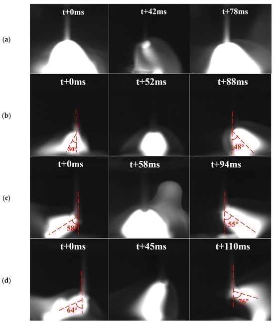
Figure 2.
Arc morphology under alternating magnetic field intensities of (a) 0 mT, (b) 10 mT, (c) 20 mT, and (d) 30 mT.
In the absence of an external magnetic field, the arc exhibits stable self-induced electromagnetic forces that are uniformly distributed along its axis. The application of a magnetic field primarily influences the charged particles within the arc plasma, resulting in electromagnetic forces that arise from the interplay between intrinsic self-induced forces and externally applied forces. Upon magnetic field imposition, significant alterations occur in arc morphology, particle motion trajectories, and arc length [17]. Figure 3 schematically illustrates the forces acting on electrons within the arc under both non-magnetic and magnetic conditions. Here, B represents the magnetic field intensity of the alternating magnetic field applied. When the direction of the magnetic field alternates, the direction of the induced Lorentz forces (FM1, FM2) also reverses. Additionally, electrons are subject to three main forces: the electric field force (FEF), the thermal expansion force (FE), and the electromagnetic confinement force (FC).
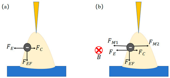
Figure 3.
Arc electron force analysis: (a) without alternating magnetic field and (b) with alternating magnetic field.
Under alternating magnetic fields, the arc plasma exhibits lateral oscillations. Notably, the external electromotive force induces tilting of the arc, which alters the distribution of self-induced electromagnetic forces. This modification creates a coupled interaction between the external and intrinsic magnetic fields [18]. A force balance analysis focused on arc electrons reveals critical insights. Given the negligible mass of electrons (me ≈ 9.109 × 10⁻³¹ kg), gravitational effects are disregarded. As the intensity of the alternating magnetic field increases, the coupled outward electromagnetic force becomes more pronounced, which is manifested macroscopically as progressively larger arc deflection angles. This mechanistic framework aligns with the observed nonlinear relationship between magnetic flux density and arc dynamics.
When an external alternating magnetic field is applied, the magnetic head generates two transverse alternating magnetic fields parallel to the weld seam direction. Divergent or convergent magnetic flux lines permeate the arc zone, as illustrated in Figure 3. To simplify the analysis, a single-electron force diagram is presented (Figure 3). According to the Lorentz force law, electrons experience a Lorentz force (FM) that is perpendicular to the substrate plane. Variations in the direction of the magnetic field induce changes in the rotational forces acting on charged particles, which in turn prompt helical motion within the arc plasma. Driven by the electric field force (FE), particles migrate from the welding wire tip toward the base metal, resulting in a spiral downward trajectory [19].
The penetration of alternating magnetic flux lines into the arc zone enhances the rotational dynamics of charged particles under magnetic confinement, thereby amplifying lateral arc oscillations. This magnetohydrodynamic interaction directly correlates with the observed arc deflection behavior, where increased rotational amplitudes under higher magnetic flux densities manifest as pronounced left–right arc oscillations.
3.2. Influence of Alternating Magnetic Field Intensity on Microstructure
TIG bead-on-plate welding was performed on stainless steel plates under varying alternating magnetic field intensities. The length of the weld bead was 80 mm, and the cross-section was cut at the middle position of the weld. The weld morphologies and corresponding quantitative metrics are illustrated in Figure 4. As the alternating magnetic field intensity increased, the weld penetration depth gradually decreased, while the weld width progressively increased, with a minor fluctuation observed at 10 mT. At 30 mT, the penetration depth reached a minimum of 1.8 mm, representing a 44% reduction compared to the non-magnetic condition, while the weld width peaked at 9.3 mm, corresponding to a 9.4% increase relative to the baseline. This is because, with the increase in the intensity of the alternating magnetic field, on the one hand, higher magnetic field intensities intensify agitation within the molten pool, improving metal fluidity and redistributing thermal energy [20]. On the other hand, the alternating magnetic field generates a cyclic and reciprocating Lorentz force, which promotes the diffusion of the molten metal to both sides of the molten pool, facilitates the interface fusion between the base metal and the filler metal on both sides of the molten pool, and, at the same time, the molten metal dispersing in the direction of penetration depth [21]. Therefore, as the intensity of the alternating magnetic field increases, the penetration depth of the weld seam gradually decreases and the width of the weld penetration gradually increases.
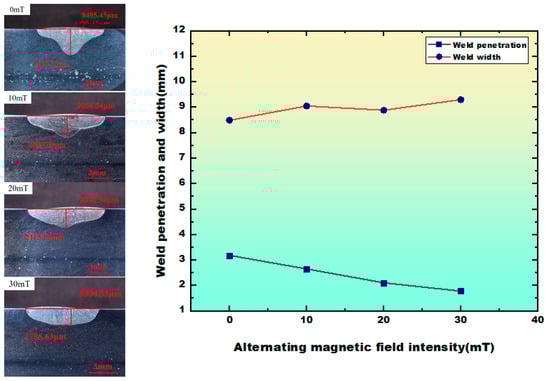
Figure 4.
Cross-sectional weld morphology and variations in weld penetration and width as functions of alternating magnetic field intensity (0–30 mT).
Figure 5 shows the microstructure of bead-on-plate welding metal under varying alternating magnetic field intensities. As shown in Figure 5a,b, the microstructure primarily consists of lath ferrite and blocky austenite. With the increase in alternating magnetic field intensity, the lath ferrite exhibits progressive fragmentation, accompanied by pronounced grain refinement. At 30 mT, the ferrite grains attain their finest dimensions [22]. The microstructural evolution, particularly the fragmentation of lath ferrite and the refinement of grains under increasing alternating magnetic field intensity, can be attributed to several interrelated mechanisms [23,24]. Firstly, with the increase in magnetic field intensity, the electromagnetic stirring effect in the molten pool is more intense, which can reduce the growth of columnar dendrites during solidification. The broken dendrites act as additional nucleation sites to promote grain refinement. Secondly, the electromagnetic stirring effect accelerates the convection of the molten pool, promotes the temperature distribution of the arc plasma to be more uniform, and prolongs the duration of the solid-phase transition. This mechanism leads to the size change in the weld pool width expansion and length contraction. It effectively reduces the thermal gradient, promotes the diffusion of elements, and promotes the complete phase transformation, thus contributing to the refinement of ferrite grains [25].
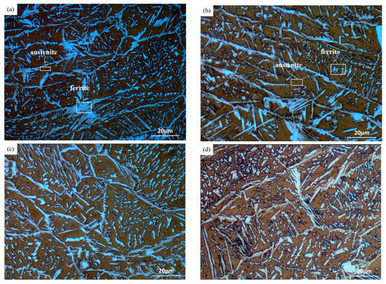
Figure 5.
Microstructure of bead-on-plate welding under alternating magnetic field intensities: (a) 0 mT; (b) 10 mT; (c) 20 mT; and (d) 30 mT.
3.3. Influence of Alternating Magnetic Field Intensity on Corrosion Performance
The polarization curves and electrochemical impedance spectroscopy (EIS) of 304 stainless steel TIG-welded joints under varying alternating magnetic field intensities in a 3.5 wt% NaCl solution are presented in Figure 6. Potentiodynamic polarization curves were obtained by continuously scanning the electrode potential at a controlled rate while measuring instantaneous current densities (Figure 6a). Despite consistent polarization trends observed across all conditions, the weld metal demonstrated passivation behavior as the corrosion potential (Ecorr) increased. Notably, the breakdown potential of the weld metal increased with the intensity of the magnetic field, indicating that the protective ability of the passive film gradually increases and its corrosion resistance enhances.


Figure 6.
Results of electrochemical corrosion of the TIG-welded SS304 joints in 3.5 wt% pct NaCl solution: (a) polarization curves, (b) Nyquist curves, (c) mode of impedance in Bode plots, (d) phase angle of impedance in Bode plots, (e) corrosion potential, (f) corrosion current density, and (g) equivalent electric circuit.
The Tafel extrapolation analysis of the potentiodynamic polarization curves yielded the fitting results shown in Figure 6e,f. The corrosion current density followed a descending order, i.e., 0 mT > 10 mT > 20 mT > 30 mT, while the corrosion potential exhibited an ascending sequence, i.e., 30 mT > 20 mT > 10 mT > 0 mT. A lower corrosion current density and higher corrosion potential are widely recognized as the hallmarks of superior corrosion resistance in working electrodes. Corrosion current density is determined by the characteristics of the passive film. This indicates that the welded joint obtained by optimizing the alternating magnetic field intensity can form a passive film with good protective ability, which reduces the corrosion sensitivity of the welded joint [26].
Notably, the passivation potential (Ecorr) of specimens under alternating magnetic fields was markedly lower than that of non-magnetic counterparts, suggesting the accelerated formation of stable passive films that effectively shield the weld from corrosive media. The corrosion resistance hierarchy of welded joints across alternating magnetic field intensities is conclusively ranked as follows: 30 mT > 20 mT > 10 mT > 0 mT.
Figure 6b displays the Nyquist plots of weld metal under varying alternating magnetic field intensities. As the intensity of the alternating magnetic field increases, the radius of the Nyquist plot progressively enlarges. According to electrochemical impedance theory, a larger capacitive arc radius indicates a greater difficulty in charge transfer at the metal–solution interface. This phenomenon suggests the formation of a thicker passive film, which is associated with a slower electrochemical reaction rate. This observation demonstrates that enhanced alternating magnetic field intensity strengthens the impedance effect of the passive film formed on the weld metal surface, thereby reflecting the improved corrosion resistance of the weld [27].
The electrochemical impedance behavior during the process was interpreted using an equivalent circuit model comprising solution resistance (R1), CPE is a constant phase element, Rp1 is the resistance of the loose outer layer, and Rp2 is the resistance of the barrier film, which correspond to the high-frequency, mid-frequency, and low-frequency regions in the Bode plots, respectively (Figure 6c,d). The fitted equivalent circuit diagram is shown in Figure 6g [28]. Fitting results are presented in Figure 6e,f. As detailed in Table 3, the solution resistance R1 exhibits minor fluctuations, indicating the stable ionic conductivity of the electrolyte. As can be seen from Table 3, the resistance value of Rp2 is two orders of magnitude higher than that of Rp1. Therefore, Rp2 is a critical parameter for evaluating the passive film protectiveness and the corrosion resistance of materials, and it is positively correlated with the magnetic field intensity. The progressive enlargement of Rp2 values under increasing alternating magnetic field intensities (0–30 mT) confirms the enhanced corrosion resistance of the weld metal. Due to the complicated corrosion process, the capacitor of passive film is not ideal. Therefore, CPE is used to describe the shift from the ideal capacitor, and n is the CPE exponent. For n = 0, CPE is resistance, whilst CPE behaves as capacitance for n = 1 [29]. These observations align with the potentiodynamic polarization curve analyses, collectively demonstrating a descending order of corrosion resistance for welded joints under alternating magnetic fields: 30 mT > 20 mT > 10 mT > 0 mT. This enhancement in corrosion resistance is attributed to the magnetically optimized characteristics of the weld and interfacial electrochemical kinetics [30].
Table 3.
Fitting results of impedance spectra.
4. Conclusions
This paper mainly investigates the effect of alternating magnetic field intensity on the arc behavior, microstructure, and corrosion properties of the deposited metal in stainless steel TIG welding. The main conclusions are as follows:
- The high-speed imaging analysis of arc morphology under varying alternating magnetic field intensities reveals that the arc remains stable without deflection in the absence of a magnetic field. However, as the intensity of the magnetic field increases, the arc exhibits pronounced periodic oscillations.
- The variation in alternating magnetic field intensity affects the penetration depth and width of the weld. As the alternating magnetic field intensity rises, the weld penetration depth diminishes gradually, whereas the weld width broadens progressively.
- The microstructure shows that, as the intensity of the alternating magnetic field increases, there is a significant phenomenon of grain refinement.
- The electrochemical tests confirmed the variations in the corrosion behavior of welded joints subjected to different intensities of alternating magnetic fields. Notably, the corrosion resistance exhibited a marked improvement with increasing alternating magnetic field intensity. The corrosion resistance of the welded joints under alternating magnetic fields can be ranked in a descending order as follows: 30 mT > 20 mT > 10 mT > 0 mT.
Author Contributions
J.W.: conceptualization, investigation, data curation, experiments, and writing—original draft preparation. J.L.: investigation and supervision. H.W.: data curation and supervision. Z.J.: writing—review and editing and writing—original draft preparation. J.F.: funding acquisition and writing—review and editing. Y.Z.: software, experiments, supervision, and funding acquisition. Q.Z.: investigation and funding acquisition. All authors have read and agreed to the published version of the manuscript.
Funding
This research was funded by Natural Science Foundation of Jiangsu Province, Grants No BK20241010.
Data Availability Statement
The original contributions presented in the study are included in the article, further inquiries can be directed to the corresponding author.
Conflicts of Interest
The authors declare no conflicts of interest.
References
- Yu, H.; Wu, W.; Zhang, X.; Fang, Z.; Fu, X.; Xu, L.; Liu, J. Optimization-based global liquefied natural gas shipping network management for emission reduction. Ocean Eng. 2025, 321, 120366. [Google Scholar] [CrossRef]
- Wang, S. Chinese high manganese steel “Meng” goes viral. China Ship Surv. 2022, 6, 30–33. [Google Scholar]
- Thakur, A.; Kumar, A.; Sharma, S.; Ganjoo, R.; Assad, H. Computational and Experimental Studies on the Efficiency of Sonchus Arvensis as Green Corrosion Inhibitor for Mild Steel in 0.5 M HCl Solution. Mater. Today Proc. 2022, 66, 609–621. [Google Scholar] [CrossRef]
- Ambade, S.; Tembhurkar, C.; Rokde, A.; Gupta, S.; Shelare, S.; Prakash, C.; Gupta, L.R.; Smirnov, V.A. Experimental investigation of microstructural, mechanical and corrosion properties of 316L and 202 austenitic stainless steel joints using cold metal transfer welding. J. Mater. Res. Technol. 2023, 27, 5881–5888. [Google Scholar] [CrossRef]
- Pavan, A.R.; Arivazhagan, B.; Vasudevan, M.; Prasanthi, T.N.; Sudha, C. Study on the microstructure and mechanical properties of hybrid laser+MIG welded joints of 316LN stainless steel. Opt. Laser Technol. 2023, 163, 109410. [Google Scholar] [CrossRef]
- Sakthivel, T.; Vasudevan, M.; Laha, K.; Parameswaran, P.; Chandravathi, K.S.; Mathew, M.D.; Bhaduri, A.K. Comparison of creep rupture behaviour of type 316L(N) austenitic stainless steel joints welded by TIG and activated TIG welding processes. Mater. Sci. Eng. A-Struct. Mater. Prop. Microstruct. Process 2011, 528, 6971–6980. [Google Scholar] [CrossRef]
- Pandya, D.; Badgujar, A.; Ghetiya, N. A novel perception toward welding of stainless steel by activated TIG welding: A review. Mater. Manuf. Process 2021, 36, 877–903. [Google Scholar] [CrossRef]
- Dong, Y.; Han, Y.; Yong, H.; De, J.; Dong, L.; Yong, P.; Ke, H. Droplet transfer behavior and weld formation of gas metal arc welding for high nitrogen austenitic stainless steel. J. Manuf. Process. 2021, 65, 491–501. [Google Scholar] [CrossRef]
- Azevedo, S.C.; Resende, A.A. Effect of angle distance between electrodes and TIG current on the weld bead geometry in TIG-MIG/MAG welding process. Int. J. Adv. Manuf. Technol. 2021, 114, 1505–1515. [Google Scholar] [CrossRef]
- Ghumman, K.Z.; Ali, S.; Din, E.U.; Mubashar, A.; Khan, N.B.; Ahmed, S.W. Experimental investigation of effect of welding parameters on surface roughness, micro-hardness and tensile strength of AISI 316L stainless steel welded joints using 308L filler material by TIG welding. J. Mater. Res. Technol. 2022, 21, 220–236. [Google Scholar] [CrossRef]
- Dhilip, A.; Jayakrishnan, N. Investigating the effects of ultrasonic assistance on TIG welding of AA7075 alloys: A machine learning-based optimization study using RSM-PSO. Phys. Scr. 2025, 100, 016002. [Google Scholar]
- Yang, C.; Yang, F.; Meng, X.; Putra, S.N.; Bachmann, M.; Rethmeier, M. Phase-Field Simulation of the Dendrite Growth in Aluminum Alloy AA5754 during Alternating Current Electromagnetic Stirring Laser Beam Welding. Int. J. Heat Mass Transf. 2024, 218, 124754. [Google Scholar] [CrossRef]
- Yue, J.; Zhou, H.; Xie, C.; Zhou, W.; Liu, W. Temperature Field Simulation and Asymmetric Heat Transfer Distribution of Dissimilar Steel Welded with External Transverse Magnetic Field. Mater. Today Commun. 2023, 37, 107141. [Google Scholar] [CrossRef]
- Tan, C.; Liu, Y.; Xu, B.; Wang, H.; Liu, F.; Gong, X.; Zeng, Z.; Chen, B.; Song, X. Numerical and Experimental Study of Thermal Fluid Flow and Keyhole Dynamic in Laser Welding of Aluminum Alloy Assisted by Electromagnetic Field. Opt. Laser Technol. 2023, 157, 108718. [Google Scholar] [CrossRef]
- Zhu, Z.; Ma, X.; Wang, C.; Mi, G. Modification of droplet morphology and arc oscillation by magnetic field in laser-MIG hybrid welding. Opt. Lasers Eng. 2020, 131, 106138. [Google Scholar] [CrossRef]
- Cai, B.; Fu, J.; Zhao, Y.; Chen, F.; Qin, Y.; Song, S. Effect of Alternating Magnetic Field on Arc Plasma Characteristics and Droplet Transfer during Narrow Gap Laser-MIG Hybrid Welding. Metals 2021, 11, 1712. [Google Scholar] [CrossRef]
- Wang, J.; Sun, Q.; Zhang, T.; Zhang, S.; Liu, Y.; Feng, J. Arc characteristics in alternating magnetic field assisted narrow gap pulsed GTAW. J. Mater. Process. Technol. 2018, 254, 254–264. [Google Scholar] [CrossRef]
- Wang, L.; Chen, J.; Wu, C.; Luan, S.C. Numerical analysis of arc and droplet behaviors in gas metal arc welding with external compound magnetic field. J. Mater. Process. Technol. 2020, 282, 116638. [Google Scholar] [CrossRef]
- Li, Y.; Miao, J.; Zou, W.; Dong, Z.H.; Chang, C.H.; Liu, D.; Chang, Y.L. Effect of an external magnetic field on arc geometry, weld microstructure and porosity of GMAW. J. Mater. Sci. 2023, 58, 1769–1782. [Google Scholar] [CrossRef]
- Fu, J.; Zhao, Y.; Zou, J.; Liu, X.; Pan, Y. Influence of the magnetic field on the melting and solidification behavior of narrow-gap laser welding with filler wire. Int. J. Adv. Manuf. Technol. 2022, 123, 1123–1131. [Google Scholar] [CrossRef]
- Zhang, L.; Tan, H.; Lin, H.; Lv, P.; Lin, L.; Zhou, J. Research on the Al/Cu dissimilar metals laser welding process with alternating magnetic field assisted. Opt. Lasers Eng. 2025, 184, 108686. [Google Scholar] [CrossRef]
- Liu, F.; Tan, C.; Ma, G.; Han, X.; Chen, B.; Song, X.; Wang, G. Improvement of inhomogeneity of microstructure and mechanical properties for 316 stainless steel laser-MIG hybrid welded joint assisted by alternating magnetic field. Sci. Technol. Weld. Join. 2022, 27, 437–445. [Google Scholar] [CrossRef]
- Chen, L.; Liang, S.; Liu, Y.; Zhang, L. Additive manufacturing of metalliclattice structures: Unconstrained design, accurate fabrication, fascinated performances, and challenges. Mater. Sci. Eng. R 2021, 146, 100648. [Google Scholar] [CrossRef]
- Chen, L.; Qin, P.; Zhang, L.; Zhang, L. An overview of additively manufactured metal matrix composites: Preparation, performance, and challenge. Int. J. Extrem. Manuf. 2024, 6, 052006. [Google Scholar] [CrossRef]
- Chen, Y.; Sui, F.; Cong, K.; Yan, X.; Zhang, G.; Guan, S. Effects of shielding gas and magnetic field on characteristics of AZ31 magnesium alloy by TIG welding. Mater. Sci. Forum 2012, 2, 1186–1196. [Google Scholar] [CrossRef]
- Juan, I.A.; Gregory, J.G.; Geoff, W.; Amit, D. Understanding the corrosion behaviour of Al-Mg alloy fabricated using a Laser Powder Bed Fusion (L-PBF) Additive Manufacturing (AM) process. J. Alloys Compd. 2023, 969, 172300. [Google Scholar]
- Guo, J.; Wang, F.; Zhou, L.; Zhao, Y.; Fu, J.; Chen, G.; Qin, Y. The Synergistic Enhancement Effect of H2 in the Shielding Gas on High Welding Efficiency and Corrosion Resistance in TIG Welding of Stainless Steel. Metall. Mater. Trans. B 2025, 1, 46–63. [Google Scholar] [CrossRef]
- Cui, Y.; Chen, L.; Chu, Y.; Zhang, L.; Li, R.; Lu, S.; Wang, L.; Zhang, L. Metastable pitting corrosion behavior and characteristics of passive film of laser powder bed fusion produced Ti-6Al-4V in NaCl solutions with different concentrations. Corros. Sci. 2023, 215, 111017. [Google Scholar] [CrossRef]
- Chen, L.; Zhang, H.; Zheng, C.; Yang, H.; Qin, P.; Zhao, C.; Lu, S.; Liang, S.; Chai, L.; Zhang, L. Corrosion behavior and characteristics of passive films of laser powder bed fusion produced Ti-6Al-4V in dynamic Hank’s solution. Mater. Des. 2021, 208, 109907. [Google Scholar] [CrossRef]
- Zhu, J.; Liu, Z.; Yuan, H.; Zhou, H.; Qiao, Y.; Xu, X.; Zou, J. Effects of different carbides content and brazing process on the electrochemical behaviour of vacuum brazed WC-10Ni+NiCrBSi coatings. Phys. Scr. 2023, 98, 115977. [Google Scholar] [CrossRef]
Disclaimer/Publisher’s Note: The statements, opinions and data contained in all publications are solely those of the individual author(s) and contributor(s) and not of MDPI and/or the editor(s). MDPI and/or the editor(s) disclaim responsibility for any injury to people or property resulting from any ideas, methods, instructions or products referred to in the content. |
© 2025 by the authors. Licensee MDPI, Basel, Switzerland. This article is an open access article distributed under the terms and conditions of the Creative Commons Attribution (CC BY) license (https://creativecommons.org/licenses/by/4.0/).