Article

Effect of Si Doping on Microstructure and Mechanical and Electrochemical Properties of (AlCrFeNi)100-xSix (x = 2, 4, 6) Dual-Phase Eutectic High-Entropy Alloys

State Key Laboratory of Metastable Materials Science and Technology, Yanshan University, Qinhuangdao 066004, China
*
Author to whom correspondence should be addressed.
Metals 2025, 15(7), 762; https://doi.org/10.3390/met15070762
Submission received: 19 June 2025 / Revised: 4 July 2025 / Accepted: 4 July 2025 / Published: 6 July 2025
(This article belongs to the Special Issue High-Entropy Alloys: Processing and Properties)

Abstract

The effects of silicon (Si) doping on the microstructure, mechanical properties, and electrochemical corrosion behavior of dual-phase eutectic high-entropy alloys (AlCrFeNi)100-xSix (x = 2, 4, 6 at.%) were systematically investigated. The results reveal that with increasing Si content, all three alloys maintain a sunflower-like eutectic microstructure composed of A2 and B2 phases, characterized by an expanding central region and a densification and refinement of the lamellar two-phase structure in the petal regions; the volume of phase B2 gradually increases, accompanied by the precipitation of nanoscale B2 particles. The test results of mechanical properties show that Si doping enhances the compressive strength and Vickers hardness but significantly reduces ductility, exhibiting a typical inverse strength–ductility relationship. Electrochemical corrosion tests demonstrate that higher Si content deteriorates corrosion resistance, with corrosion predominantly occurring in the B2 phase. Among the studied alloys, the Si2 variant exhibits the most balanced overall performance. This work provides valuable insights into the role of Si in tuning the microstructure and properties of eutectic high-entropy alloys and methodology for their compositional design and engineering applications.

1. Introduction

In recent years, high-entropy alloys (HEAs) have emerged as a prominent research focus in materials science due to their unique multi-principal element design strategy and exceptional properties, including mechanical strength, thermal stability, and corrosion resistance [1,2,3,4,5,6,7]. Compared with conventional alloys, high-entropy alloys are capable of forming stable solid solution phases in complex compositional systems, exhibiting outstanding properties such as high strength, excellent ductility, and superior corrosion resistance [8,9,10,11,12,13,14]. Systematic studies of high-entropy alloy systems’ thermodynamic equilibrium and non-equilibrium dynamic evolution via molecular dynamics simulations and first-principles calculations are of great scientific significance [15,16,17,18]. However, the compositional complexity of certain HEAs often leads to poor castability, coarse grain structures, and elemental segregation during processing, which hinders further enhancement of their strength–ductility synergy and limits their industrial applicability. Eutectic high-entropy alloys (EHEAs), by contrast, achieve a remarkable balance between strength and toughness through the formation of multiphase eutectic microstructures during solidification. These alloys offer controllable microstructural morphology, excellent castability, and simultaneously exhibit high strength, good ductility, and favorable processing adaptability, thus providing a promising pathway for practical engineering applications [19,20,21,22,23,24].
Eutectic high-entropy alloys possess broad application potential in structural materials, owing to their stable microstructures, refined lamellar morphologies, and synergistic deformation mechanisms among constituent phases [25,26,27,28,29,30]. For instance, Song et al. [31] introduced Nb into an Fe2NiCr alloy, promoting the formation of a Laves phase and successfully developed an Fe2NiCrNb0.34 eutectic alloy comprising FCC and Laves phases. This alloy exhibited a remarkable fracture strength of 2267 MPa and a fracture strain of 30.8%, demonstrating a well-balanced combination of strength and ductility. The eutectic microstructure effectively refines the grain size, enhances interface-induced strengthening, and improves resistance to deformation. Moreover, cooperative deformation between different phases helps to alleviate local stress concentrations [32,33,34]. Jin et al. [35] developed an Fe20Co20Ni41Al19 EHEA featuring a nanoscale lamellar microstructure composed of B2 and L12 phases. This alloy achieved a tensile strength of 1103 MPa and a total elongation of 18.7% at room temperature, outperforming most as-cast HEAs. In another study, Kang et al. [36] added W and C to the MoNbTa system, forming a refined lamellar dual-phase (BCC + FCC) eutectic structure. The combination of eutectic organization and W, C incorporation led to simultaneous enhancements in both ductility and high-temperature strength.
As engineering materials, the corrosion resistance of EHEAs under service environments plays a critical role in determining their longevity and stability. Shuang et al. [37] designed an FeCrNiCoNb0.5 EHEA and conducted electrochemical testing along with microstructural characterization. The results revealed a low corrosion current density, a wide passive region, and excellent repassivation ability, which were attributed to the formation of a dense passive film during corrosion and the presence of a two-phase nanoscale lamellar eutectic structure. Zhang et al. [38] examined the corrosion and passivation behavior of CoCrFeNiNbₓ (x = 0.3, 0.45, 0.6) eutectic high-entropy alloys in various electrolyte solutions. Among them, the Nb0.45 alloy exhibited the best corrosion resistance in Na2SO4 solution, with a pitting potential reaching as high as 1.084 V(vs. SCE).
As a typical non-metallic element, silicon (Si) plays a vital role in high-entropy alloy systems by participating in crystal structure regulation, refining the microstructure, and enhancing structural stability [39,40,41,42]. Moreover, during corrosion processes, Si is closely associated with passive film behavior and interfacial dissolution mechanisms [43,44]. Lin et al. [45] designed CoCrFeMnNiSix HEA coatings and investigated the relationships among their microstructure, mechanical properties, and corrosion resistance. With increasing Si content, the alloy structure evolved from a single-phase FCC to a combination of FCC, BCC, and silicide phases. The Si1.6 alloy achieved an average hardness of 513.2 HV0.5, approximately 1.77 times that of the Si0 counterpart. Wear resistance improved significantly, with volume loss decreasing from 0.0814 mm3 to 0.0291 mm3, alongside enhanced corrosion resistance. Xu et al. [46] studied the effects of Si on the microstructure and mechanical properties of the refractory NbMoTiVW HEA. Increasing Si content led to a structural transition from a single BCC phase to a eutectic structure comprising primary BCC, silicide, and secondary BCC phases. Si addition refined the BCC grains and increased their volume fraction, which contributed to the formation of a eutectic morphology and improved the ultimate compressive strength from 2242 MPa to 2532 MPa.
Based on this background, the present study focuses on (AlCrFeNi)100-xSix (x = 2, 4, 6 at.%) alloys. By microstructural characterization analyzing, compressive mechanical testing, and electrochemical polarization experiments, we systematically investigated the effects of Si doping on the structural evolution, mechanical behavior, and corrosion performance of the alloys. The findings aim to provide theoretical insights and experimental evidence to support compositional optimization and practical applications of high-performance EHEA systems.

2. Experimental Materials and Methods

2.1. Alloy Preparation

The raw materials used for preparing the alloy in this study were from Zhongnuo New Materials Technology Co, LTD., Beijing, China. The purity was all above 99.95%, including blocky Fe, Al, Ni, and granular Si, Cr. High-purity raw materials were melted under a high-purity argon atmosphere using vacuum induction melting to prepare (AlCrFeNi)100-xSix (x = 2, 4, 6 at.%) (designated as Si2, Si4, Si6 alloys). Each ingot was re-melted at least six times to ensure chemical homogeneity.

2.2. Microstructure Characterization

The crystal structure and phase composition of the alloys were identified using X-ray diffraction (XRD, D/max-2500/PCX, Rigaku, Tokyo, Japan) with Cu Ka radiation over a scanning range of 20–100° and a scan rate of 4°/min. Prior to testing, polish the test surface of the sample with a polishing solution of 0.02 μm until it is mirror-like. Finally, clean it with alcohol and blow dry it to remove surface oxides and minimize measurement artifacts. Grain structure was examined using a scanning electron microscope (SEM; Hitachi S-3400, Hitachi High-Tech, Tokyo, Japan). The types and elemental distribution of precipitates were analyzed using a transmission electron microscope (TEM; FEl Talos F200X, Thermo Fisher Scientific, Waltham, MA, USA). Samples for TEM analysis were first mechanically ground to a thickness of approximately 50 μm, followed by twin-jet electropolishing using a Struers TenuPol-5 to produce electron-transparent regions around the perforated area.

2.3. Properties Test

The compressive properties of the alloy samples were evaluated using an INSTRON-5982 mechanical testing system. Cylindrical specimens with a height-to-diameter ratio of 2:1 (3 mm in diameter and 6 mm in height) were prepared via wire electrical discharge machining. The top, bottom, and lateral surfaces of the specimens were mechanically ground and polished to ensure flatness and parallelism. During testing, a constant compressive strain rate of 5 × 10⁻⁴ s−1 was applied, and a contact extensometer was employed to continuously monitor the change in specimen length. To ensure the reliability of the results, each alloy composition was tested at least three times.
The microhardness of the alloy samples was measured using an HVS-1000 Vickers hardness tester (Shanghai Yanrun Optical Machinery Technology Co., LTD. Shanghai, China). For each sample, at least ten indentations were performed at different locations, and the average value was taken to represent the final microhardness, ensuring accuracy and reproducibility.
The corrosion behavior of the MEAs was evaluated using an electrochemical workstation (CHI760E) in a 3.5 wt.% NaCl solution. A conventional three-electrode setup was employed, with an Ag/AgCl (1 mol/L KCl) electrode as the reference, a platinum electrode as the counter, and the alloy sample as the working electrode. Open circuit potential (OCP) was recorded for 3600 s to ensure potential stabilization before testing. Potentiodynamic polarization was then performed to assess the corrosion characteristics, with a potential scan range from −1 V to +1 V vs. Ag/AgCl and a scan rate of 1 mV/s. Electrochemical impedance spectroscopy (EIS) was conducted using a sinusoidal perturbation of 5 mV over a frequency range of 10−2 to 105 Hz. Each test was repeated three times to ensure data reliability and reproducibility. Mott–Schottky measurements were performed on the samples with passivation films formed on their surfaces. The tests were conducted using a linear potential scan in the negative direction, within the potential range of 0.2 V to −1 V (vs. reference electrode). To minimize changes in the thickness, composition, and defect density of the passive film during the scan, a potential step of 50 mV was employed. The measurement was carried out at a frequency of 1 kHz with a sinusoidal AC perturbation amplitude of 10 mV.

3. Results and Discussion

3.1. Phase and Microstructure

Figure 1a presents the X-ray diffraction (XRD) patterns of the Si2, Si4, and Si6 alloys. All three compositions exhibit a dual-phase structure, with diffraction peaks corresponding to both ordered BCC (B2) and disordered BCC (A2) phases. As the Si content increases, the intensity of the B2 phase peaks gradually becomes more pronounced, which is consistent with previous reports in the literature [47].
Figure 1b–d shows the SEM micrographs of the Si2, Si4, and Si6 alloys, respectively. All alloys display a distinctive radial microstructure propagating from the center outward, composed of alternating light and dark phases, in agreement with the XRD results. This novel sunflower-like eutectic morphology was first reported by Guo et al. in Al2CrCuFeNi2 EHEAs [48]. In this structure, uniformly distributed sunflower seed-like precipitates populate the central region, from which petal-shaped lamellae radiate outward.
The formation of this morphology is attributed to lamellar decomposition during directional growth of the A2 and B2 phases, perpendicular to the boundary of the primary solidified phase after grain formation [49,50]. With the increasing Si content, the central region of the sunflower-like eutectic structure gradually expands, while the lamellar phases in the petal region become denser and more refined. Both the enlargement of the structural core and the refinement of the dual phases within the sunflower-like eutectic morphology indicate an intensified eutectic reaction. The volume fractions of the B2 phase in the Si2, Si4, and Si6 alloys were statistically analyzed by Image j2 software, which were approximately 20.94%, 23.42%, and 27.83%, respectively. This indicates that Si promotes the formation and growth of the ordered B2 phase.
Figure 2 presents the EDS analysis results of the sunflower-like eutectic microstructure in the Si2 alloy. The results reveal that the central region consists of granular A2 phase, while the surrounding matrix is primarily composed of the B2 phase. In the petal region, a lamellar structure with alternating A2 and B2 phases is observed. The A2 phase is enriched in Cr and Fe, whereas the B2 phase is rich in Al and Ni. Notably, the Si element is relatively uniformly distributed across both phases.
To obtain a more accurate and detailed understanding of the alloy’s microstructure, transmission electron microscopy (TEM) was performed on the Si2 alloy. As shown in Figure 3a,b, the alloy exhibits a distinct sunflower-like eutectic structure. To further identify the constituent phases, a localized region of the eutectic structure was selected for analysis, as illustrated in Figure 3c. Two distinct regions (marked as 1 and 2) were chosen for selected area electron diffraction (SAED) analysis, with the corresponding diffraction patterns shown in Figure 3f,g. The spherical particles in region 1 were identified as the A2 phase, while region 2 was confirmed to be the B2 phase.
Figure 3d presents the lamellar petal-like structure of the eutectic region in the Si2 alloy. Based on the previous analyses, the alternating lamellae are composed of the A2 and B2 phases. Additionally, fine precipitates can be observed within both phases. Figure 3h,i shows the SAED patterns for regions 3 and 4, respectively, which reveal the presence of superlattice reflections characteristic of the B2 phase within the lamellar structure, indicating a well-ordered substructure in both constituent phases.
Figure 4 presents the TEM-EDS elemental mapping results, which are consistent with the previous SEM-EDS analysis. A clear compositional distinction is observed between the two phases: the A2 phase is enriched in Fe and Cr, while the B2 phase is confirmed to be rich in Ni and Al. Although Si is present in both phases, its concentration is noticeably lower in the B2 phase compared to the A2 phase.

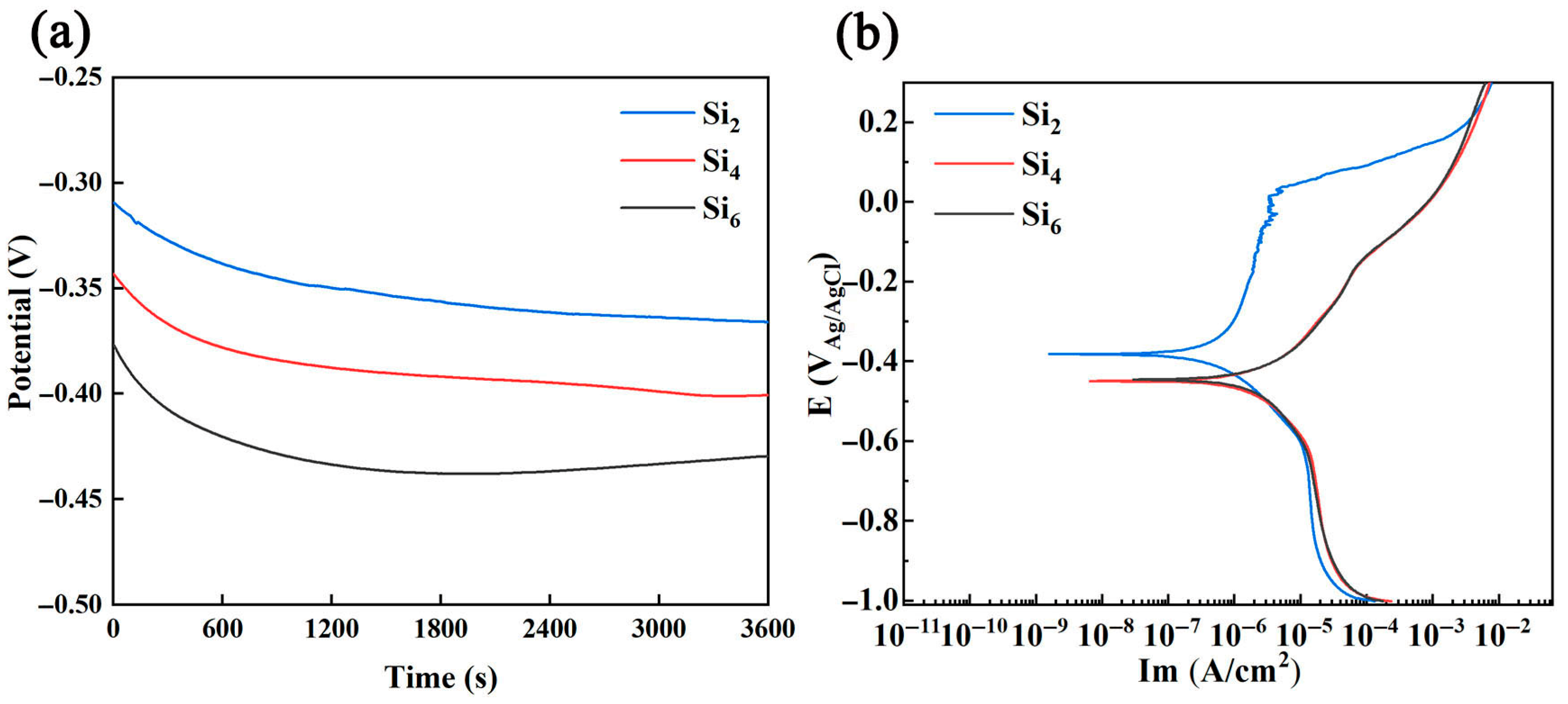
3.2. Electrochemical Test

The open circuit potential curves and potentiodynamic polarization curves of (AlCrFeNi)100-xSix alloys in a 3.5 wt.% NaCl solution in Figure 5 illustrate that the Si2 alloy exhibits a distinct passive region, indicating an active-to-passive transition occurring at approximately −0.25 V. This suggests the formation of a stable passive film on the alloy surface. As the potential increases to −0.06 V, the curve remains within the passive region; however, noticeable serrated fluctuations appear, signifying repeated breakdown and repassivation processes on the alloy surface. This behavior indicates that the passive film is no longer stable under these conditions.
In contrast, the other alloys (with higher Si content) display no clearly defined passive region, suggesting that their passive films are less stable and more prone to breakdown, resulting in accelerated corrosion.
Based on the polarization curves shown in Figure 5, key electrochemical parameters, including corrosion potential (Ecorr), corrosion current density (Icorr), critical pitting potential (Epit), passive current density (Ip), and the passivation potential range (ΔE = EpitEcorr), are summarized in Table 1. Generally, a higher Ecorr and a lower Icorr indicate better corrosion resistance [51,52]. According to Table 1, the Si2 alloy exhibits the most favorable electrochemical characteristics, confirming its superior corrosion resistance. Therefore, the corrosion resistance of the three high-entropy alloys follows the order Si2 > Si4 > Si6.
Figure 6 displays the corrosion morphology of the Si2 alloy after electrochemical testing. Evidently, corrosion is primarily concentrated in certain regions of the central zone and the petal-like lamellar structures. The granular precipitates in the central area remain relatively intact, while the rod-like precipitates in the petal region show periodic corrosion damage. These precipitates are primarily associated with the B2 phase, which acts as the anodic phase during corrosion, undergoing preferential dissolution and thereby protecting the cathodic A2 phase [53].
As shown in Figure 4, the A2 phase is mainly composed of Cr, Fe, and Si, whereas the B2 phase is predominantly NiAl. The Cr element in the A2 phase contributes to the formation of a protective chromium oxide/hydroxide film, which provides strong corrosion resistance. Consequently, the B2 phase, being less protected, undergoes anodic dissolution during the corrosion process. Based on the above content, the schematics of the corrosion mechanism are shown in Figure 6c–e.
Nyquist and Bode plots of the (AlCrFeNi)100-xSix alloys measured under open circuit potential (OCP) conditions in a 3.5 wt.% NaCl solution are shown in Figure 7. The result in Figure 7a indicates that all alloys exhibit semicircular arcs due to charge transfer occurring on their heterogeneous surfaces. Typically, a larger semicircle diameter corresponds to a higher charge transfer resistance and a thicker, more protective oxide layer, indicating better corrosion resistance [54]. Clearly the order of the semicircle diameters is Si2 > Si4 > Si6, suggesting that the Si2 alloy exhibits the best corrosion resistance.
Furthermore, as shown in Figure 7b, the |Z| values at a frequency of 0.01 Hz follow the order of Si2 (1.44 × 10⁵ Ω·cm2) > Si4 (5.03 × 10⁴ Ω·cm2) > Si6 (3.25 × 10⁴ Ω·cm2), which further supports the conclusion drawn from the Nyquist plot. Additionally, the maximum phase angle at around 10 Hz remains below –90°, indicating non-ideal capacitive behavior caused by surface heterogeneity.
To account for this behavior, a constant phase element (CPE) was introduced, of which the electrical impedance is defined as follows [55,56]:
Z C P E = Y 0 1 ( j ω ) n
Among them, ω and j represent angular frequency and imaginary units, respectively. Y0 represents the admittance order of CPE, and the value of n indicates that CPE deviates from the ideal capacitive characteristics, changing from 0 to 1. The value of n can change from 0 (ideal pure resistance) to 1 (ideal pure capacitance), which is related to non-uniform surfaces. The equivalent circuit model used to simulate the EIS data is shown in the inset of Figure 7a, and the fitted results are listed in Table 2. According to the data in Table 2, the exponent n of the CPE in all alloys is less than 1, indicating that the alloy surfaces exhibit relatively smooth capacitive behavior. The film resistance (Rf) and charge transfer resistance (Rct) of all samples are in the same order of magnitude (approximately 104 Ω), and together they determine the stability and protective quality of the passive film. Therefore, the corrosion resistance of the materials can be effectively evaluated using the polarization resistance Rp (Rct + Rf) [53,57].
Figure 8 presents the Mott–Schottky plots of the passive films formed on the surface of (AlCrFeNi)100-xSix alloys after immersion in 3.5 wt.% NaCl solution. According to Mott-Schottky theory, the relationship between space charge capacitance (C) and applied potential (E) of the semiconductor can be expressed by the following equation [58,59]:
1 C 2 = 2 ε ε 0 e N D ( E E FB K T e )   f o r   n - t y p e
1 C 2 = 2 ε ε 0 e N A ( E E FB K T e )   f o r   p - t y p e
where ε is the relative dielectric constant of the passive film (assumed to be 15.6), ε0 is the permittivity of vacuum (8.854  × 10−14 F/cm), e is the electron charge (1.602 × 10⁻¹⁹ C), NA and ND, respectively, are the acceptor and donor densities for p-type and n-type semiconductors, EFB is the flat band potential, K is the Boltzmann constant (1.38 × 10⁻²³ J/K), and T is the absolute temperature. As shown in the figure, the Si2 alloy exhibits the steepest positive and negative slopes among all tested compositions. The donor density (ND), acceptor density (NA), and flat band potential (EFB) of the oxide films were calculated and are summarized in Table 3.
As observed in Table 3, both ND and NA increase with increasing Si content. This is primarily attributed to the precipitation of a large amount of B2 and A2 phases at grain boundaries induced by Si addition. Moreover, the increase in Si content promotes the formation of SiO2 with higher oxidation states in the passive film. Due to the smaller atomic radius and grain size of Si, SiO2 tends to occupy interstitial sites, resulting in enhanced lattice distortion effects [34,46]. Because the Si2 alloy exhibits the lowest donor and acceptor densities among the tested alloys, it implies the lowest concentration of point defects in both n-type and p-type semiconducting regions of the passive film. Consequently, the Si2 alloy forms the most protective and stable passive film, providing superior corrosion resistance.

3.3. Mechanical Property Test

Figure 9a displays the compressive stress–strain curves of as-cast (AlCrFeNi)100-xSix alloys with varying Si content. As shown, compared to the Si2 alloy, the other two compositions exhibit higher yield strength and fracture strength, but significantly reduced ductility—particularly in the case of the Si6 alloy. Notably, the Si2 alloy demonstrates an excellent combination of strength and plasticity, with a fracture strength of 3260 MPa and a plastic strain of 33.8%. With increasing Si content, the degree of lattice distortion is expected to rise due to the atomic size mismatch between Si and the principal elements (Al, Cr, Fe, Ni). This leads to enhanced solid solution strengthening, contributing to the observed increase in yield strength. The increase in lattice distortion also impedes dislocation motion. Our microstructural quantification reveals that the volume fraction of the ordered B2 phase increases from ~20.9% to ~27.8% as Si content increases from 2 to 6 at.%. The B2 phase, being harder and more brittle than the disordered A2 matrix, contributes to strength but reduces plastic deformation capacity. The accumulation of strain at the A2/B2 interfaces may lead to early crack initiation and propagation, which is particularly evident in the Si6 alloy.
Figure 9b shows the Vickers hardness (HV) values of the as-cast (AlCrFeNi)100-xSix alloys. From Si2 to Si6, the hardness consistently increases with increasing Si content. These results indicate that the addition of an appropriate amount of Si facilitates the formation of a sunflower-like eutectic structure in the alloy, which contributes to the enhancement of its overall mechanical properties [48,50]. Table 4 presents the mechanical property data of the (AlCrFeNi)100-xSix alloys corresponding to the results shown in Figure 9.

4. Conclusions

In this work, (AlCrFeNi)100-xSix (x = 2, 4, 6) eutectic high-entropy alloys were prepared. The microstructure was characterized and analyzed, and the corrosion and mechanical properties of the three alloys were systematically investigated. The main conclusions are summarized as follows:
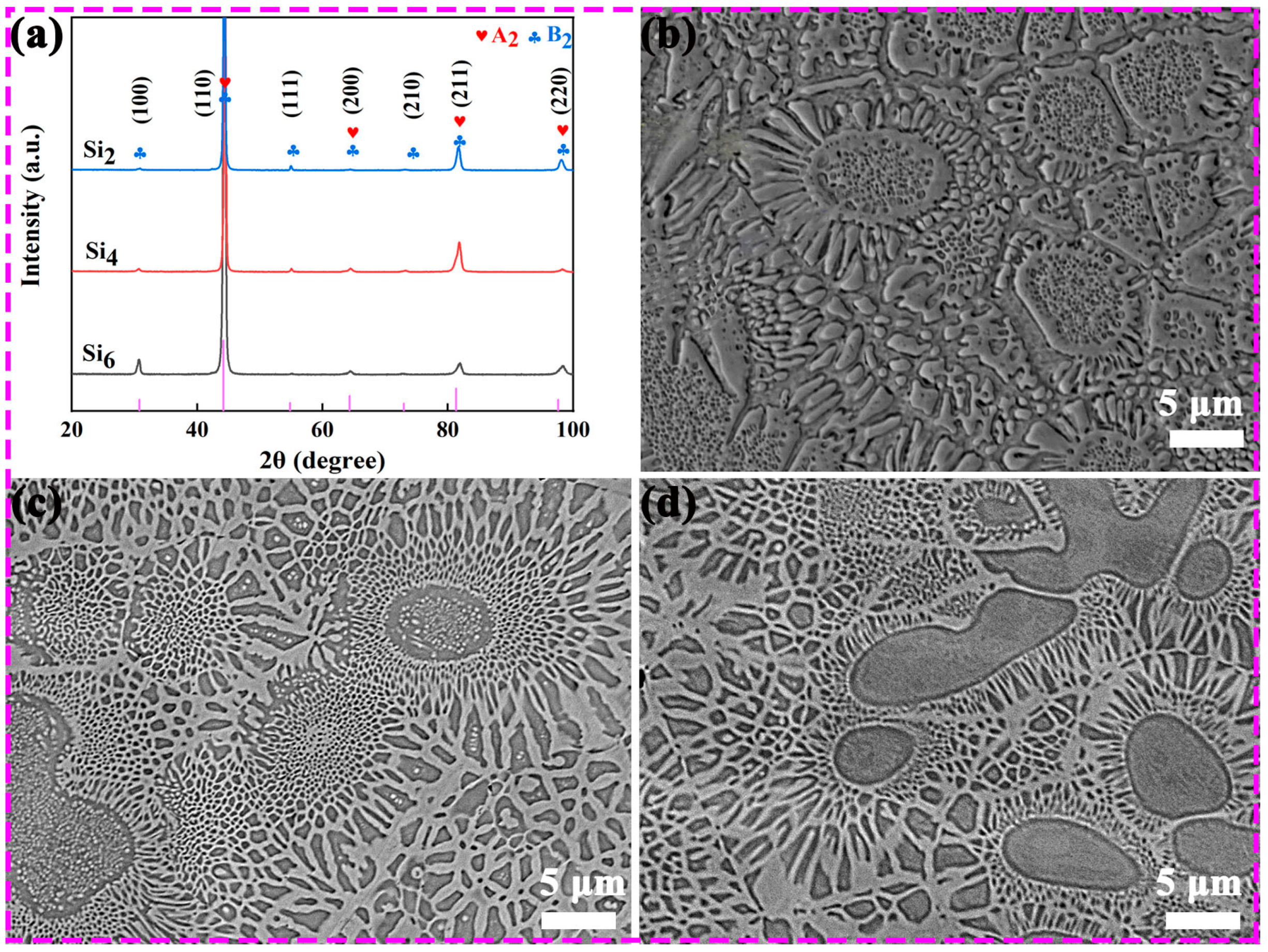
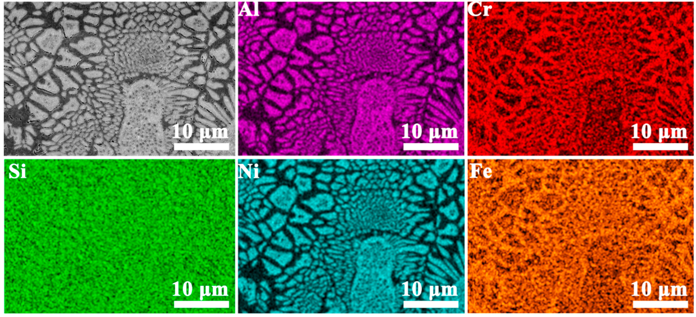
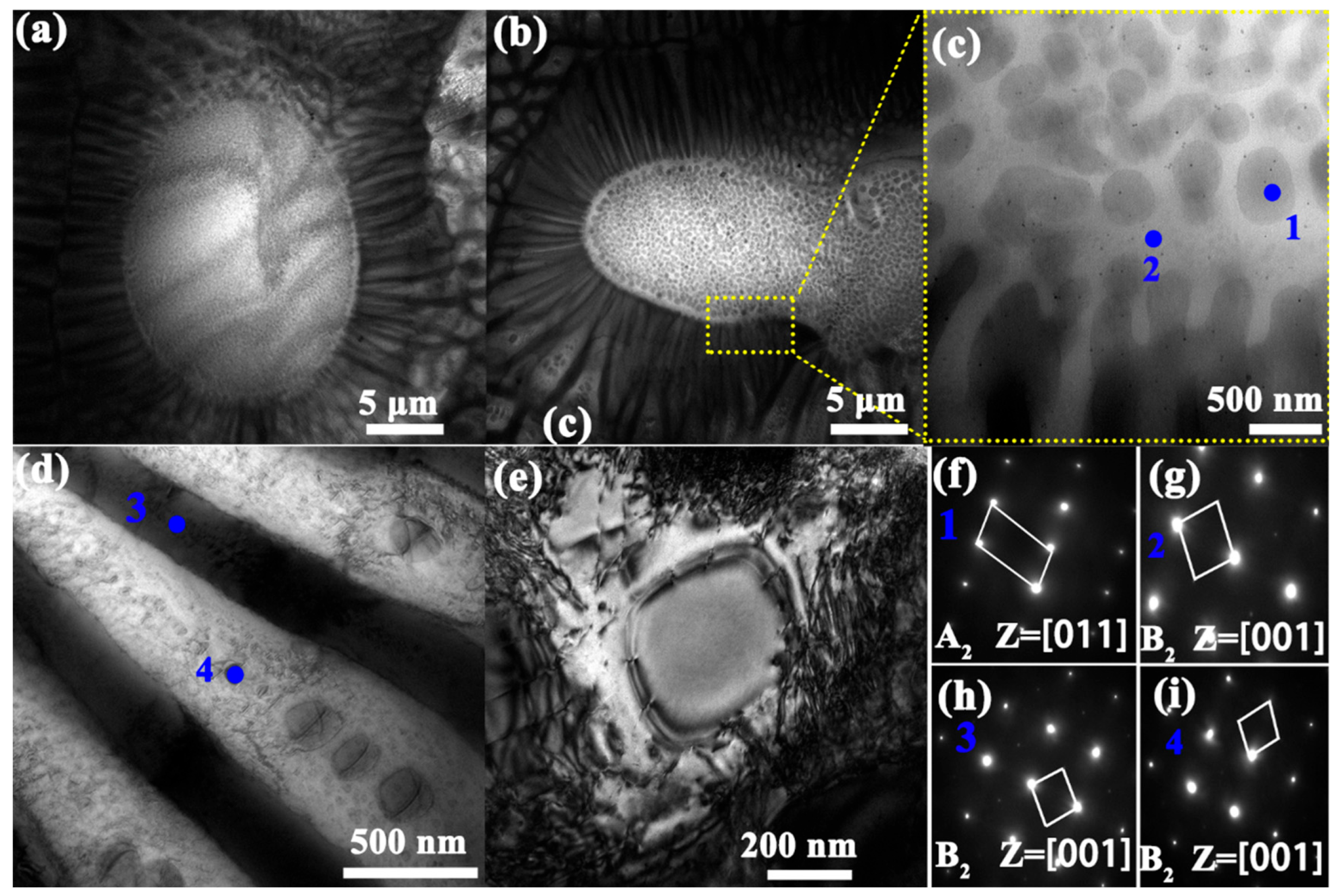
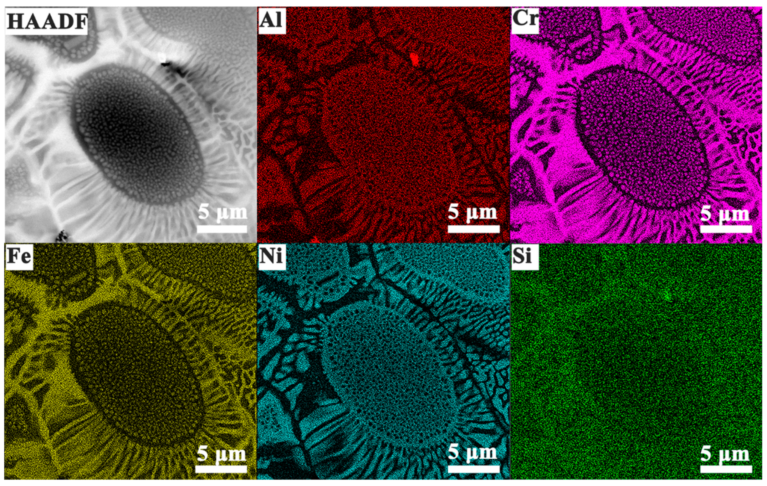
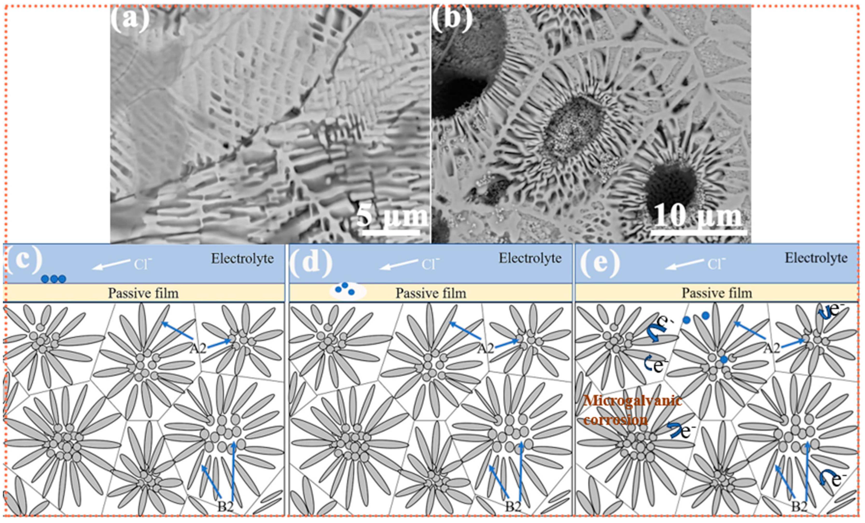
  • With increasing Si content, all three alloys retained a sunflower-like eutectic microstructure composed of A2 and B2 phases. The central region of the microstructure gradually expanded, while the two-phase lamellar “petal” regions became denser and more refined. The volume fraction of the ordered B2 phase increased from ~20.9% to ~27.8% as Si content increased from 2 to 6 at.%. The B2 phase was enriched in Al and Ni elements, whereas the A2 phase was enriched in Cr, Fe, and Si. Nanometer-scale B2 precipitates were observed in both phases within the petal regions.
  • The corrosion resistance of the alloys decreased with increasing Si content. Among them, the Si2 alloy exhibited the best corrosion performance, with a corrosion potential (Ecorr) of −381.6 mV (vs. Ag/AgCl) and a corrosion current density (Icorr) of 486.9 nA/cm2. Galvanic corrosion occurred between the two phases, where the A2 phase acted as the cathode and was protected, while the B2 phase served as the anode and was preferentially corroded.
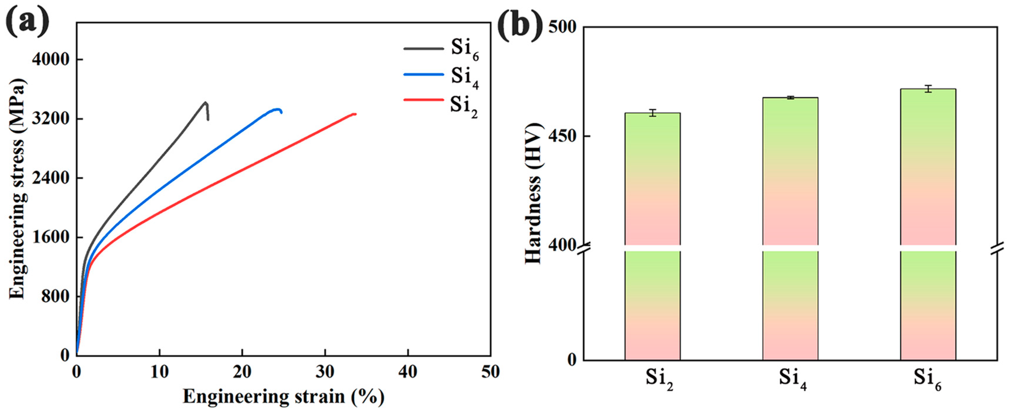
  • The compressive strength and Vickers hardness of the alloys increased with higher Si content, while the plasticity showed a significant decline. The Si2 alloy demonstrated excellent comprehensive mechanical properties, with a fracture strength of 3261 MPa, plastic strain of 33.8%, and a Vickers hardness of 461 HV.

Author Contributions

Conceptualization, K.K. and B.Z.; methodology, S.Y.; software, K.K. and A.L.; validation, S.Y., B.Z. and A.L.; formal analysis, S.Y. and K.K.; investigation, A.L. and B.Z.; resources, G.L.; data curation, S.Y. and A.L.; writing—original draft preparation, S.Y.; writing—review and editing, G.L.; visualization, B.Z.; supervision, S.Y. and K.K.; project administration, G.L.; funding acquisition., G.L. All authors have read and agreed to the published version of the manuscript.

Funding

This research was funded by National Key Research and Development Program of China, grant number 2022YFA1603800 and National Natural Science-Foundation of China, grant number 12274362.

Data Availability Statement

The original contributions presented in this study are included in the article. Further inquiries can be directed to the corresponding author.

Acknowledgments

This work was financial supported by the National Key Research and Development Program of China·(No. 2022YFA1603800), and the National Natural Science-Foundation of China·(No. 12274362).

Conflicts of Interest

The authors declare no conflicts of interest.

References

  1. Hsu, W.L.; Tsai, C.W.; Yeh, A.C.; Yeh, J.W. Clarifying the four core effects of high-entropy materials. Nat. Rev. Chem. 2024, 8, 471–485. [Google Scholar] [CrossRef] [PubMed]
  2. Balaji, V.; Xavior, M.A. Development of high entropy alloys (HEAs): Current trends. Heliyon 2024, 10, 23. [Google Scholar]
  3. Lu, Z.P.; Wang, H.; Chen, M.W.; Baker, I.; Yeh, J.W.; Liu, C.T.; Nieh, T.G. An assessment on the future development of high-entropy alloys: Summary from a recent workshop. Intermetallics 2015, 66, 67–76. [Google Scholar] [CrossRef]
  4. Wu, Y.Q.; Liaw, P.K.; Li, R.X.; Zhang, W.R.; Geng, G.H.; Yan, X.H.; Liu, G.Q.; Zhang, Y. Relationship between the unique microstructures and behaviors of high-entropy alloys. Int. J. Miner. Metall. Mater. 2024, 31, 1350–1363. [Google Scholar] [CrossRef]
  5. George, E.P.; Raabe, D.; Ritchie, R.O. High-entropy alloys. Nat. Rev. Mater. 2019, 4, 515–534. [Google Scholar] [CrossRef]
  6. Zhang, Y.L.; Jiang, X.S.; Fang, Y.; Fang, Y.J.; Liu, B.; Sun, H.L.; Shao, Z.Y.; Song, T.F. Research and development of welding methods and welding mechanism of high-entropy alloys: A review. Mater. Today Commun. 2021, 28, 21. [Google Scholar] [CrossRef]
  7. Yeh, J.W. Alloy Design Strategies and Future Trends in High-Entropy Alloys. JOM 2013, 65, 1759–1771. [Google Scholar] [CrossRef]
  8. Wang, Z.J.; Xing, F.; Xu, G.J.; Liu, W.J.; Bian, H.Y. Microstructure and mechanical properties of additive manufactured TiC-reinforced Fe55Cr25Co10Ni10 high-entropy alloy composites. Opt. Laser Technol. 2025, 187, 11. [Google Scholar] [CrossRef]
  9. Yan, X.; Guo, H.; Yang, W.; Pang, S.; Wang, Q.; Liu, Y.; Liaw, P.K.; Zhang, T. Al0.3CrXFeCoNi high-entropy alloys with high corrosion resistance and good mechanical properties. J. Alloy. Compd. 2021, 860, 158436. [Google Scholar] [CrossRef]
  10. Kang, K.W.; Li, A.X.; Zhang, J.S.; Xu, M.K.; Huang, D.; Che, C.N.; Liu, S.K.; Jiang, Y.T.; Li, Y.Q.; Li, G. Revealing the oxidation behavior of AlCrXFeNi lightweight multi-principal element alloys via experimental and first-principles calculations. J. Alloys Compd. 2024, 1008, 176622. [Google Scholar] [CrossRef]
  11. Li, R.; Liu, X.S.; Yu, P.F.; Fan, X.F.; Tong, X.; Liu, Q.Q.; Lu, Y.; Zhang, Y.F.; Li, G. Synthesis and characterization of a ultrafine grained (CoCrFeNi)80Mn10Ti10 multi-principal element alloy nanocomposite. Mater. Sci. Eng. A 2022, 833, 9. [Google Scholar] [CrossRef]
  12. Fan, X.F.; Li, R.; Liu, X.S.; Liu, Q.Q.; Tong, X.; Li, A.X.; Xu, S.; Yang, H.; Yu, P.F.; Li, G. Synergistic strengthening of heterogeneous structures and dual-morphology nano-precipitates in Co1.5CrNi1.5Al0.2Ti0.1V0.1 medium-entropy alloy. Mater. Sci. Eng. A 2022, 832, 8. [Google Scholar] [CrossRef]
  13. Li, A.; Liu, X.; Li, R.; Yu, S.; Jiang, M.; Zhang, J.; Che, C.; Huang, D.; Yu, P.; Li, G. Double heterogeneous structures induced excellent strength–ductility synergy in Ni40Co30Cr20Al5Ti5 medium-entropy alloy. J. Mater. Sci. Technol. 2024, 181, 176–188. [Google Scholar] [CrossRef]
  14. Jiang, Y.T.; Li, A.X.; Kang, K.W.; Zhang, J.S.; Huang, D.; Che, C.N.; Liu, S.K.; Xu, M.K.; Li, Y.Q.; Zhang, B.R.; et al. Effect of Multi-Phase Composite Structure on the Mechanical Properties of AlXFe1.5CoNiC0.12 High Entropy Alloys. Metals 2025, 15, 203. [Google Scholar] [CrossRef]
  15. Jin, W.K.Y.; Sharma, P.; Singh, P.; Kundu, A.; Balasubramanian, G.; Chan, H.M. Solid State Reduction Driven Synthesis of Mn Containing Multi-principal Component Alloys. Metall. Mater. Sci. 2024, 55, 3799–3808. [Google Scholar] [CrossRef]
  16. Shi, Z.L.; Liu, Y.Z.; Zhang, H.R.; Li, C.Z.; Chen, S.N.; Yang, Y.J.; Liang, S.X.; Ma, M.Z. Synergistic strength-ductility enhancement of CoCrFeNi high-entropy alloys with regulated Co/Cr atomic ratios. Mater. Sci. Eng. A 2024, 912, 10. [Google Scholar] [CrossRef]
  17. Nataraj, C.; Borda, E.J.L.; Walle, A.; Samanta, A. A systematic analysis of phase stability in refractory high entropy alloys utilizing linear and non-linear cluster expansion models. Acta Mater. 2021, 220, 17. [Google Scholar] [CrossRef]
  18. Ye, Y.F.; Zhang, Y.H.; He, Q.F.; Zhuang, Y.; Wang, S.; Shi, S.Q.; Hu, A.; Fan, J.; Yang, Y. Atomic-scale distorted lattice in chemically disordered equimolar complex alloys. Acta Mater. 2018, 150, 182–194. [Google Scholar] [CrossRef]
  19. Lu, Y.P.; Dong, Y.; Jiang, H.; Wang, Z.J.; Cao, Z.Q.; Guo, S.; Wang, T.M.; Li, T.J.; Liaw, P.K. Promising properties and future trend of eutectic high entropy alloys. Scr. Mater. 2020, 187, 202–209. [Google Scholar] [CrossRef]
  20. Lu, Y.P.; Jiang, H.; Guo, S.; Wang, T.M.; Cao, Z.Q.; Li, T.J. A new strategy to design eutectic high-entropy alloys using mixing enthalpy. Intermetallics 2017, 91, 124–128. [Google Scholar] [CrossRef]
  21. Liu, Q.Q.; Liu, X.S.; Fan, X.F.; Li, R.; Tong, X.; Yu, P.F.; Li, G. Designing novel AlCoCrNi eutectic high entropy alloys. J. Alloy. Compd. 2022, 904, 7. [Google Scholar] [CrossRef]
  22. Wang, M.L.; Lu, Y.P.; Wang, T.M.; Kundu, A.; Balasubramanian, G.; Chan, H.M. A novel bulk eutectic high-entropy alloy with outstanding as-cast specific yield strengths at elevated temperatures. Scr. Mater. 2021, 204, 7. [Google Scholar] [CrossRef]
  23. Ye, X.C.; Diao, Z.H.; Kang, H.J.; Li, Z.; Li, J.H.; Qu, Z.X.; Wang, L.; Zhao, G.W.; Li, B. A New Strategy for the Design of Triple-Phase Eutectic High-Entropy Alloys Based on Infinite Solid Solution and Pseudo-Ternary Method. Nano Lett. 2024, 24, 6117–6123. [Google Scholar] [CrossRef]
  24. Xie, T.B.; Xiong, Z.P.; Xu, Z.Q.; Cheng, X.W. Varying the eutectic composition of Co-Cr-Fe-Ni-Hf high-entropy system using a modified simple mixture method. Mater. Sci. Eng. A Struct. Mater. Prop. Microstruct. Process. 2020, 786, 5. [Google Scholar] [CrossRef]
  25. Xiong, T.; Zheng, S.J.; Pang, J.Y.; Ma, X.L. High-strength and high-ductility AlCoCrFeNi2.1 eutectic high-entropy alloy achieved via precipitation strengthening in a heterogeneous structure. Scr. Mater. 2020, 186, 336–340. [Google Scholar] [CrossRef]
  26. Gao, X.Z.; Lu, Y.P.; Zhang, B.; Liang, N.N.; Wu, G.Z.; Sha, G.; Liu, J.Z.; Zhao, Y.H. Microstructural origins of high strength and high ductility in an AlCoCrFeNi2.1 eutectic high-entropy alloy. Acta Mater. 2017, 141, 59–66. [Google Scholar] [CrossRef]
  27. Lu, Y.P.; Dong, Y.; Guo, S.; Jiang, L.; Kang, H.J.; Wang, T.M.; Wen, B.; Wang, Z.J.; Jie, J.C.; Cao, Z.Q.; et al. A Promising New Class of High-Temperature Alloys: Eutectic High-Entropy Alloys. Sci. Rep. 2014, 4, 5. [Google Scholar] [CrossRef]
  28. Shi, P.J.; Ren, W.L.; Zheng, T.X.; Ren, Z.M.; Hou, X.L.; Peng, J.C.; Hu, P.F.; Gao, Y.F.; Zhong, Y.B.; Liaw, P.K. Enhanced strength-ductility synergy in ultrafine-grained eutectic high-entropy alloys by inheriting microstructural lamellae. Nat. Commun. 2019, 10, 8. [Google Scholar] [CrossRef]
  29. Wang, J.M.; Jiang, H.; Xie, W.L.; Kong, X.; Qin, S.X.; Yao, H.W.; Li, Y. Effect of Mo addition on microstructural evolution and corrosion behaviors of AlCrFeNi3 eutectic high-entropy alloy. Corros. Sci. 2024, 229, 111879. [Google Scholar] [CrossRef]
  30. Liu, J.H.; Li, Z.H.; Lin, D.Y.; Tang, Z.X.; Song, X.G.; He, P.; Zhang, S.Y.; Bian, H.; Fu, W.; Song, Y.Y. Eutectic high-entropy alloys and their applications in materials processing engineering: A review. J. Mater. Sci. Technol. 2024, 189, 211–246. [Google Scholar] [CrossRef]
  31. Song, J.F.; Chai, Z.S.; Zheng, J.; Wu, Q.F.; He, F.; Yang, Z.N.; Li, J.J.; Wang, J.C.; Yang, H.O.; Wang, Z.J. Design Fe-based Eutectic Medium-Entropy Alloys Fe2NiCrNbX. Acta Metall. Sin. Engl. Lett. 2021, 34, 1103–1108. [Google Scholar] [CrossRef]
  32. Lu, Y.P.; Gao, X.Z.; Jiang, L.; Chen, Z.N.; Wang, T.M.; Jie, J.C.; Kang, H.J.; Zhang, Y.B.; Guo, S.; Ruan, H.H.; et al. Directly cast bulk eutectic and near-eutectic high entropy alloys with balanced strength and ductility in a wide temperature range. Acta Mater. 2017, 124, 143–150. [Google Scholar] [CrossRef]
  33. Lu, Y.P.; Gao, X.X.; Dong, Y.; Wang, T.M.; Chen, H.L.; Mao, H.H.; Zhao, Y.H.; Jiang, H.; Cao, Z.Q.; Li, T.J.; et al. Preparing bulk ultrafine-microstructure high-entropy alloys via direct solidification. Nanoscale 2018, 10, 1912–1919. [Google Scholar] [CrossRef] [PubMed]
  34. Lu, Y.P.; Wu, X.X.; Fu, Z.H.; Yang, Q.K.; Zhang, Y.; Liu, Q.M.; Li, T.X.; Tian, Y.Z.; Tan, H.; Li, Z.M.; et al. Ductile and ultrahigh-strength eutectic high-entropy alloys by large-volume 3D printing. J. Mater. Sci. Technol. 2022, 126, 15–21. [Google Scholar] [CrossRef]
  35. Jin, X.; Zhou, Y.; Zhang, L.; Du, X.Y.; Li, B.S. A novel Fe20Co20Ni41Al19 eutectic high entropy alloy with excellent tensile properties. Mater. Lett. 2018, 216, 144–146. [Google Scholar] [CrossRef]
  36. Kang, K.J.; Wang, X.; Zhou, W.B.; Li, P.B.; Huang, Z.H.; Luo, G.Q.; Shen, Q.; Zhang, L.M. Eutectic MoNbTa(WC)X Composites with Excellent Elevated Temperature Strength. Metals 2023, 13, 687. [Google Scholar] [CrossRef]
  37. Shuang, S.; Ding, Z.Y.; Chung, D.; Shi, S.Q.; Yang, Y. Corrosion resistant nanostructured eutectic high entropy alloy. Corros. Sci. 2020, 164, 14. [Google Scholar] [CrossRef]
  38. Zhang, F.Y.; Zhang, L.J.; Wei, X.M.; Zhang, C.Z.; Jia, Q.X.; Sun, K.; Duan, D.T.; Li, G. Corrosion and passive behaviors of the Co-Cr-Fe-Ni-Nb eutectic high-entropy alloys in different electrolyte solutions. Intermetallics 2025, 177, 16. [Google Scholar] [CrossRef]
  39. Wei, D.X.; Gong, W.; Tsuru, T.; Lobzenko, I.; Li, X.Q.; Harjo, S.; Kawasaki, T.; Do, H.S.; Bae, J.W.; Wagner, C.; et al. Si-addition contributes to overcoming the strength-ductility trade-off in high-entropy alloys. Int. J. Plast. 2022, 159, 18. [Google Scholar] [CrossRef]
  40. Zhang, Z.K.; Hua, K.; Cao, Y.; Song, Y.Q.; Li, X.L.; Zhou, Q.; Wang, H.F. Microstructures and properties of FeCrAlMoSix high entropy alloy coatings prepared by laser cladding on a titanium alloy substrate. Surf. Coat. Technol. 2024, 478, 13. [Google Scholar] [CrossRef]
  41. Aravindh, S.A.; Kistanov, A.A.; Alatalo, M.; Kömi, J.; Huttula, M.; Cao, W. Incorporation of Si atoms into CrCoNiFe high-entropy alloy: A DFT study. J. Phys. Condens. Matter 2021, 33, 12. [Google Scholar] [CrossRef] [PubMed]
  42. Wang, G.; Yang, Y.L.; He, R.J.; Tan, C.W.; Huttula, M.; Cao, W. A novel high entropy CoFeCrNiCu alloy filler to braze SiC ceramics. J. Eur. Ceram. Soc. 2020, 40, 3391–3398. [Google Scholar] [CrossRef]
  43. Gao, W.B.; Feng, M.Y.; Chen, C.R.; Lian, G.F. Microstructure evolution, wear resistance and corrosion resistance of CoCrCu0.5FeNiSiX high-entropy alloy coatings fabricated by laser cladding. J. Mater. Res. Technol. JmrT 2025, 36, 5539–5558. [Google Scholar] [CrossRef]
  44. Guo, W.; Gong, M.L.; Huang, L.T.; Wagn, K.Y.; Qu, H.Z.; Liu, F.F.; Bai, J.; Gao, Q.Z.; Zhao, X.; Li, S. Microstructure and Properties of FeCoNiCuSix High Entropy Alloys. Sci. Adv. Mater. 2022, 14, 122–129. [Google Scholar]
  45. Lin, T.X.; Feng, M.Y.; Lian, G.F.; Lu, H.; Chen, C.R.; Huang, X. Effects of Si content on the microstructure and properties of CoCrFeMnNiSix high-entropy alloy coatings by laser cladding. Mater. Charact. 2024, 216, 17. [Google Scholar] [CrossRef]
  46. Xu, Q.; Wang, Q.; Chen, D.Z.; Fu, Y.A.; Shi, Q.S.; Yin, Y.J.; Zhang, S.Y. Microstructure characteristics and mechanical properties of NbMoTiVWSix refractory high-entropy alloys. China Foundry 2022, 19, 495–502. [Google Scholar] [CrossRef]
  47. Liu, S.K.; Li, A.X.; Kang, K.W.; Zhang, J.S.; Huang, D.; Che, C.N.; Jiang, Y.T.; Xu, M.K.; Zhang, B.R.; Li, Y.Q.; et al. Microstructure and Performance of Body-Centered Cubic-Based Dual-Phase Composite Eutectic High-Entropy Alloys Prepared by Si Doping. Metals 2025, 15, 207. [Google Scholar] [CrossRef]
  48. Guo, S.; Ng, C.; Liu, C.T. Anomalous solidification microstructures in Co-free AlxCrCuFeNi2 high-entropy alloys. J. Alloy. Compd. 2013, 557, 77–81. [Google Scholar] [CrossRef]
  49. Guo, S.; Ng, C.; Liu, C.T. Sunflower-like Solidification Microstructure in a Near-eutectic High-entropy Alloy. Mater. Res. Lett. 2013, 1, 228–232. [Google Scholar] [CrossRef]
  50. Jiang, Z.F.; Chen, W.P.; Xia, Z.B.; Xiong, W.; Fu, Z.Q. Influence of synthesis method on microstructure and mechanical behavior of Co-free AlCrFeNi medium-entropy alloy. Intermetallics 2019, 108, 45–54. [Google Scholar] [CrossRef]
  51. Shi, Y.Z.; Yang, B.; Xie, X.; Brechtl, J.; Dahmen, K.A.; Liaw, P.K. Corrosion of Al xCoCrFeNi high-entropy alloys: Al-content and potential scan-rate dependent pitting behavior. Corros. Sci. 2017, 119, 33–45. [Google Scholar] [CrossRef]
  52. Shi, Y.Z.; Collins, L.; Balke, N.; Liaw, P.K.; Yang, B. In-situ electrochemical-AFM study of localized corrosion of AlxCoCrFeNi high-entropy alloys in chloride solution. Appl. Surf. Sci. 2018, 439, 533–544. [Google Scholar] [CrossRef]
  53. Zhao, Q.; Pan, Z.; Wang, X.; Luo, H.; Liu, Y.; Li, X. Corrosion and passive behavior of AlXCrFeNi3−X (x = 0.6, 0.8, 1.0) eutectic high entropy alloys in chloride environment. Corros. Sci. 2022, 208, 110666. [Google Scholar] [CrossRef]
  54. Chen, X.D.; Li, Y.S.; Zhu, Y.T.; Chen, Y.F.; Yang, B. Layer-by-layer corrosion behavior of 316LN stainless steel with a gradient-nanostructured surface. Electrochem. Commun. 2020, 110, 8. [Google Scholar] [CrossRef]
  55. Pardo, A.; Merino, M.C.; Coy, A.E.; Viejo, F.; Arrabal, R.; Matykina, E. Pitting corrosion behaviour of austenitic stainless steels—combining effects of Mn and Mo additions. Corros. Sci. 2008, 50, 1796–1806. [Google Scholar] [CrossRef]
  56. Della Rovere, C.A.; Alano, J.H.; Silva, R.; Nascente, P.A.P.; Otubo, J.; Kuri, S.E. Characterization of passive films on shape memory stainless steels. Corros. Sci. 2012, 57, 154–161. [Google Scholar] [CrossRef]
  57. Wang, Z.; Zhang, G.H.; Fan, X.H.; Jin, J.; Zhang, L.; Du, Y.X. Corrosion behavior and surface characterization of an equiatomic CoCrFeMoNi high-entropy alloy under various pH conditions. J. Alloy. Compd. 2022, 900, 10. [Google Scholar] [CrossRef]
  58. Hankin, A.; Bedoya-Lora, F.E.; Alexander, J.C.; Regoutz, A.; Kelsall, G.H. Flat band potential determination: Avoiding the pitfalls. J. Mater. Chem. A 2019, 7, 26162–26176. [Google Scholar] [CrossRef]
  59. Yao, J.Z.; Macdonald, D.D.; Dong, C.F. Passive film on 2205 duplex stainless steel studied by photo-electrochemistry and ARXPS methods. Corros. Sci. 2019, 146, 221–232. [Google Scholar] [CrossRef]
Figure 1. As-cast (AlCrFeNi)100-xSix (x = 2, 4, 6) EHEAs. (a) XRD patterns, PDF#00-034-0396 for A2 and PDF#00-047-1126 for B2, (b) SEM images of Si2 alloy, (c) SEM images of Si4 alloy, (d) SEM images of Si6 alloy.
Metals 15 00762 g001
Figure 2. SEM images and EDS elemental maps of Si2 alloy.
Metals 15 00762 g002
Figure 3. TEM images of the Si2 alloy. (a,b) Bright-field images of the sunflower-like eutectic structure. (c) A magnified view of the yellow-marked region, illustrating the distribution of the two phases between the central and petal regions. (d) A bright-field image of the alternating lamellar phases and precipitates in the petal region. (e) A high-magnification bright-field image of a typical precipitate. (fi) Selected area electron diffraction (SAED) patterns corresponding to the regions marked in the images, confirming the crystallographic nature of the observed phases.
Metals 15 00762 g003
Figure 4. HAADF image and EDS elemental maps of Si2 alloy.
Metals 15 00762 g004
Figure 5. (a) Open circuit potential curves. (b) Potentiodynamic polarization curves of (AlCrFeNi)100-xSix high-entropy alloys in 3.5 wt.% NaCl solution.
Metals 15 00762 g005
Figure 6. (a,b) A SEM image of the surface of the Si2 alloy after electrochemical testing. (ce) Schematics of the corrosion mechanism.
Metals 15 00762 g006
Figure 7. (a) Nyquist and (b) Bode plots of (AlCrFeNi)100-xSix high-entropy alloys in 3.5 wt.% NaCl solution.
Metals 15 00762 g007
Figure 8. Mott–Schottky plots of the passive films formed on (AlCrFeNi)100-xSix alloys in 3.5 wt.% NaCl solution.
Metals 15 00762 g008
Figure 9. (a) Compressive stress–strain curves and (b) Vickers hardness bar charts of (AlCrFeNi)100-xSix alloys.
Metals 15 00762 g009
Table 1. Electrochemical corrosion parameters of (AlCrFeNi)100-xSix alloys determined from potentiodynamic polarization curves.
AlloysIcorr (nA/cm2)Ecorr (mVAg/AgCl)Ip (μA/cm2)Epit (mVAg/AgCl)ΔEp (mVAg/AgCl)
Si2486.92 ± 15−381.6 ± 74.66 ± 0.1335 ± 0.61416.6 ± 7.61
Si41860.15 ± 31−462.1 ± 1671.94 ± 0.44−157 ± 1.21305.1 ± 18.21
Si62024.71 ± 25−465.3 ± 1864.43 ± 0.41−170 ± 1.50295.3 ± 19.5
Table 2. Equivalent circuit fitting results of EIS data for (AlCrFeNi)100-xSix alloys.
AlloysRs (W·cm2)Rf (W·cm2)Rct (W·cm2)CPEfCPEdl
Y0f−1·cm−2·sn)nfY0dl−1·cm−2·sn)ndl
Si233.327.85 × 1048.12 × 10415.830.8936.750.94
Si432.292.81 × 1043.40 × 10418.020.9434.010.80
Si631.922.65 × 1043.42 × 10427.840.9215.830.73
Table 3. Calculated donor density (ND), acceptor density (NA), and flat band potential (EFB) values of oxide films on (AlCrFeNi)100-xSix alloys.
AlloysNA (1020 cm−3)ND (1020 cm−3)EFB (mVAg/AgCl)
Si20.681.49−0.67
Si42.392.86−0.64
Si63.092.95−0.66
Table 4. Mechanical properties at room temperature of as-cast (AlCrFeNi)100-xSix alloys.
AlloysVickers Hardness (HV)Yield Strength
σy (MPa)
Fracture Strength σf (MPa)Fracture Strain εf (%)
Si2461 ± 31272 ± 113260 ± 2133.8± 0.3
Si4468 ± 21380 ± 153319 ± 2424.7 ± 0.5
Si6475 ± 31447 ± 133436 ± 2715.2 ± 0.2
Disclaimer/Publisher’s Note: The statements, opinions and data contained in all publications are solely those of the individual author(s) and contributor(s) and not of MDPI and/or the editor(s). MDPI and/or the editor(s) disclaim responsibility for any injury to people or property resulting from any ideas, methods, instructions or products referred to in the content.

