Article

Experimental and Numerical Investigation on Fracture Behavior and Energy Absorption Characteristics of Aluminum Foam in the Taylor Tests

by
Chenyang Fan
1,*,
Xingyu Dong
2,
Youcai Xiao
2,* and
Wenzhong Lou
1
1
The School of Mechatronical Engineering, Beijing Institute of Technology, Beijing 100081, China
2
College of Mechatronic Engineering, North University of China, Taiyuan 030051, China
*
Authors to whom correspondence should be addressed.
Metals 2025, 15(12), 1313; https://doi.org/10.3390/met15121313 (registering DOI)
Submission received: 3 November 2025 / Revised: 22 November 2025 / Accepted: 27 November 2025 / Published: 28 November 2025
(This article belongs to the Section Corrosion and Protection)

Abstract

This study investigates the dynamic response characteristics of aluminum foam materials under low to medium-high velocity impact loading, elucidating their deformation mechanisms and energy absorption capabilities through an integrated experimental and numerical simulation approach. The multi-stage deformation behavior of aluminum foam was investigated through the Taylor impact test, which demonstrated that impact velocity significantly affects its stiffness and energy absorption capability. The accuracy of stress distribution and mechanical properties during the impact process is validated, and the deformation behavior under medium- and high-speed impact conditions is clearly revealed. Through integrated macroscopic and microscopic analyses, the dynamic response characteristics of aluminum foam under various impact loads are systematically investigated, elucidating the mechanisms of internal pore collapse and dynamic compressive behavior, thereby providing robust theoretical support for the optimized design of aluminum foam in cushioning and protective applications.

1. Introduction

As a lightweight and high-performance porous metal material, aluminum foam integrates the inherent mechanical strength of metals with the low density characteristic of porous structures, thereby exhibiting exceptional specific strength, superior energy absorption capacity, and excellent thermal and acoustic insulation properties, along with strong impact resistance [1,2,3,4]. Under dynamic loading conditions, aluminum foam effectively dissipates energy through plastic deformation and the localized collapse of its internal pore structure [5]. However, the dynamic response of porous materials, such as aluminum foam, is governed by multiple interrelated factors, including impact velocity, sample thickness, porosity, density gradient, and stress distribution [6,7]. Among these factors, impact velocity and specimen thickness play particularly critical roles in determining mechanical behavior [8,9].
Mukai et al. [10] investigated the dynamic compressive behavior of aluminum foam and revealed a significant strain rate sensitivity. Li et al. [11] conducted quasi-static compression tests on both empty tubes and aluminum foam-filled tubes, demonstrating that the incorporation of aluminum foam significantly improves the crashworthiness of the structures, thereby confirming its enhanced energy absorption capability. Qiu et al. [12] investigated the dynamic response of aluminum foam under compressive loading and found that the mechanical behavior is highly sensitive to strain rate, with both stress levels and energy absorption efficiency increasing as the strain rate increases—demonstrating a significant influence of strain rate on energy absorption performance. The energy absorption capacity of aluminum foam is primarily attributed to the dissipation of energy through plastic yielding, deformation, and collapse of its internal cellular structure under external loading conditions [13,14]. This capacity is directly related to the material’s deformation path during loading: increased foam thickness leads to a longer deformation path, providing a greater buffering distance and enabling more extensive plastic deformation as well as progressive pore collapse. Consequently, foam thickness plays a crucial role in determining energy absorption efficiency. Furthermore, the deformation and failure mechanisms of aluminum foam under impact loading are significantly influenced by both loading rate and thickness, resulting in complex mechanical behaviors [15]. Therefore, a comprehensive understanding of these deformation and failure mechanisms is crucial for enhancing the energy absorption and buffering capabilities of aluminum foam under dynamic loading conditions. The Taylor tests and their theoretical framework [16] in the field of porous materials began relatively late. Researchers worldwide have employed the Taylor tests to investigate the dynamic response characteristics of porous foam metals [17,18]. Notably, Lu et al. [19] developed a Taylor impact response analysis model for aluminum foam by integrating classical Taylor’s theory with experimental results, thereby revealing the variation in dynamic yield strength with projectile impact velocity. The Taylor test is a useful experiment for estimating material behavior at high impact velocity. Many researchers and engineers extended Taylor’s theory to the case of compressible materials such porous metals and metal foams [20,21,22].
The microstructural architecture of porous materials plays a crucial role in determining their physical and mechanical properties [23,24,25]. The internal pore distribution exhibits a high degree of irregularity, which significantly compromises experimental reproducibility. Given that experimental studies on the mechanical behavior of porous materials are typically resource-intensive and time-consuming, they are often ill-suited for revealing the underlying deformation mechanisms and intrinsic material properties. In contrast, Finite element simulations (FEM) provide a viable alternative for achieving a more comprehensive understanding of the mechanical behavior of porous materials under various loading conditions [26,27,28]. The existing literature has reported inconsistent findings on the influence of high impact velocity on the mechanical properties of aluminum foam under dynamic loading. The damage patterns and deformation mechanisms of aluminum foams under high-velocity loading remain uncertain.
In this study, Taylor tests were performed on aluminum foam at different impact velocities. A three-dimensional (3D) Laguerre–Voronoi tessellations (LVT) model was developed to represent a real foam, and the model accuracy was verified through experiments. The resulting numerical model was verified by comparing shock wave propagation and damage modes with the corresponding experimental findings.

2. Materials and Methods

2.1. Test Materials and Preparation

The aluminum foam specimens, which were provided by Yuantaida New Materials Co. (Nantong, China), have been widely adopted in the aerospace, vehicle, and ship industries. Closed-cell aluminum foam with a porosity of 91% was fabricated using the melt foaming method. Industrial pure aluminum (99.77% purity) was first introduced into a stainless-steel crucible and heated in a vertical resistance furnace until fully molten, with the temperature maintained at 670–680 °C. Subsequently, calcium particles accounting for 1.5 wt% of the total melt mass were added to increase melt viscosity, followed by mechanical stirring at 400 r/min for 10 min to ensure uniform dispersion and improve bubble stability. Thereafter, 2.0 wt% TiH2 powder was introduced into the molten aluminum and uniformly dispersed via vigorous mechanical stirring at 1000 r/min for 90 s. The crucial step involved transferring the crucible to a constant-temperature electric furnace, where it was maintained under precisely controlled conditions to ensure consistent and stable foam expansion. Finally, the foamed melt was solidified using a directionally controlled rapid water-cooling system with uniform coolant distribution, ensuring consistent cooling rates and effectively preserving the integrity of the closed-cell structure. Figure 1 shows a macroscopic view of aluminum foam that exhibit a density of 0.468 g/cm3 and uniform cell morphology. In the Taylor tests, the specimens were cylindrical, with a diameter of 70 mm and a length of 110 mm. The mass of specimen is 178.6 g.

2.2. Experimental System Design

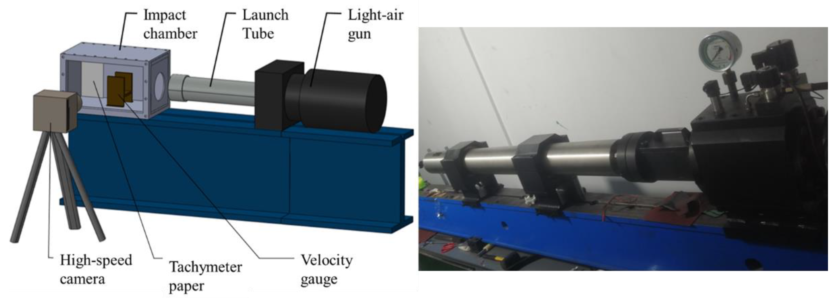
As shown in Figure 2, the experimental system comprises five subsystems: a dynamic loading system (in Figure 3), a velocity measurement system, a high-speed video acquisition system, a pressure acquisition system, and a Taylor bar. The dynamic impact loading system employs a pressurized chamber equipped with a pneumatic device to precisely control the impact velocity. A high-speed camera is utilized to capture detailed images of the impact process. Impact pressure is measured using two PVDF sensors, each capable of accurately capturing peak strain data with high temporal resolution. The target plate used in the experiments is a square 45 steel plate with side length of 100 mm and thickness of 8 mm, having a density of 7.8 × 10³ kg/m3 and an elastic modulus of 206 GPa. Anvil dimensions are 300 × 300 × 30 mm.
Once the high-pressure gas propels the projectile out of the chamber, the high-speed camera is immediately triggered to initiate image acquisition, while the oscilloscope simultaneously records stress wave signals from two PVDF sensors. Due to the porous structure and surface roughness of aluminum foam, a sabot (in Figure 2) with a diameter of 75 mm and a length of 80 mm was attached to the rear of each specimen to ensure stable flight and consistent impact velocity upon exiting the muzzle.

3. Experimental Results and Discussion

The mechanical parameters, including peak impact pressure, length of the recovered sample, maximum diameter, and mass loss of the recovered samples, were systematically evaluated under each test condition. Table 1 presents these mechanical parameters of aluminum foam under various impact velocities obtained from the Taylor tests. It is evident that the stress peak increases significantly with rising impact velocity. At an impact velocity of 255 m/s, the peak stress reaches nearly 140 MPa, whereas at 75 m/s, it is approximately 24 MPa. This demonstrates a strong dependence of the stress response in aluminum foam on impact velocity; as velocity increases, the material exhibits a higher capacity to withstand stress.
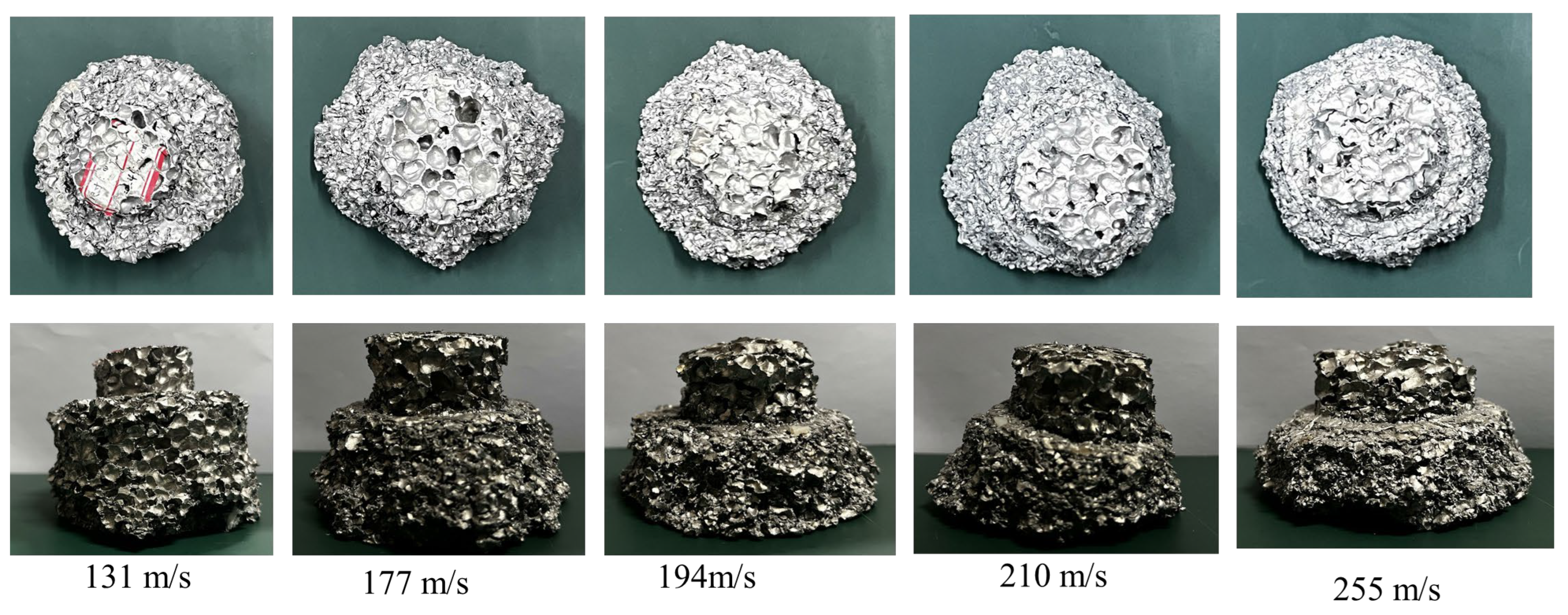
Figure 4 presents the cross-sectional views of five specimens. At the impact end, cells exhibit significant deformation, fragmentation, and compaction, resulting in localized high-density regions. Minimal damage is observed on the rear surface when the impact velocity ranges from 131 m/s to 255 m/s, with pore walls remaining largely intact. Localized damage in the outer circumferential region of the back surface is primarily attributed to the influence of the projectile sabot. At 131 m/s, approximately half of the specimen undergoes densification, and the shock front is clearly discernible. At 255 m/s, the foam specimen experiences nearly complete collapse. Due to the excessive impact load, the outermost region of the sample was completely damaged. Consequently, as the impact speed increases, the maximum diameter observed in the recovery test decreases.
Due to the extremely short duration of the compression process in the aluminum foam specimen during the Taylor impact test, a high-speed camera was employed to capture the failure evolution. The recorded images show that the specimen maintained an almost horizontal orientation upon impact with the vertical target plate immediately after exiting the muzzle. As shown in Figure 5, the process of aluminum foam under impact, from initiation to completion, was captured using a high-speed camera. During the impact process, aluminum foam undergoes progressive layer-by-layer collapse. As the first layer of cells is fully compacted, the subsequent layer begins to experience compressive deformation. Under high-velocity impact conditions, deformation is localized near the contact region with the rigid wall, where inertial effects dominate the material response. Localized pore walls experience compression, buckling, or rupture, accompanied by lateral expansion. Due to stress concentration and inertial effects at the impact front, a localized region of high-density compression gradually forms. Within this zone, pores progressively close, material density increases, and plastic deformation with yielding occurs. Simultaneously, the plastic compression zone in the aluminum foam steadily propagates rearward, giving rise to a continuously compressing region followed by an undeformed trailing section.
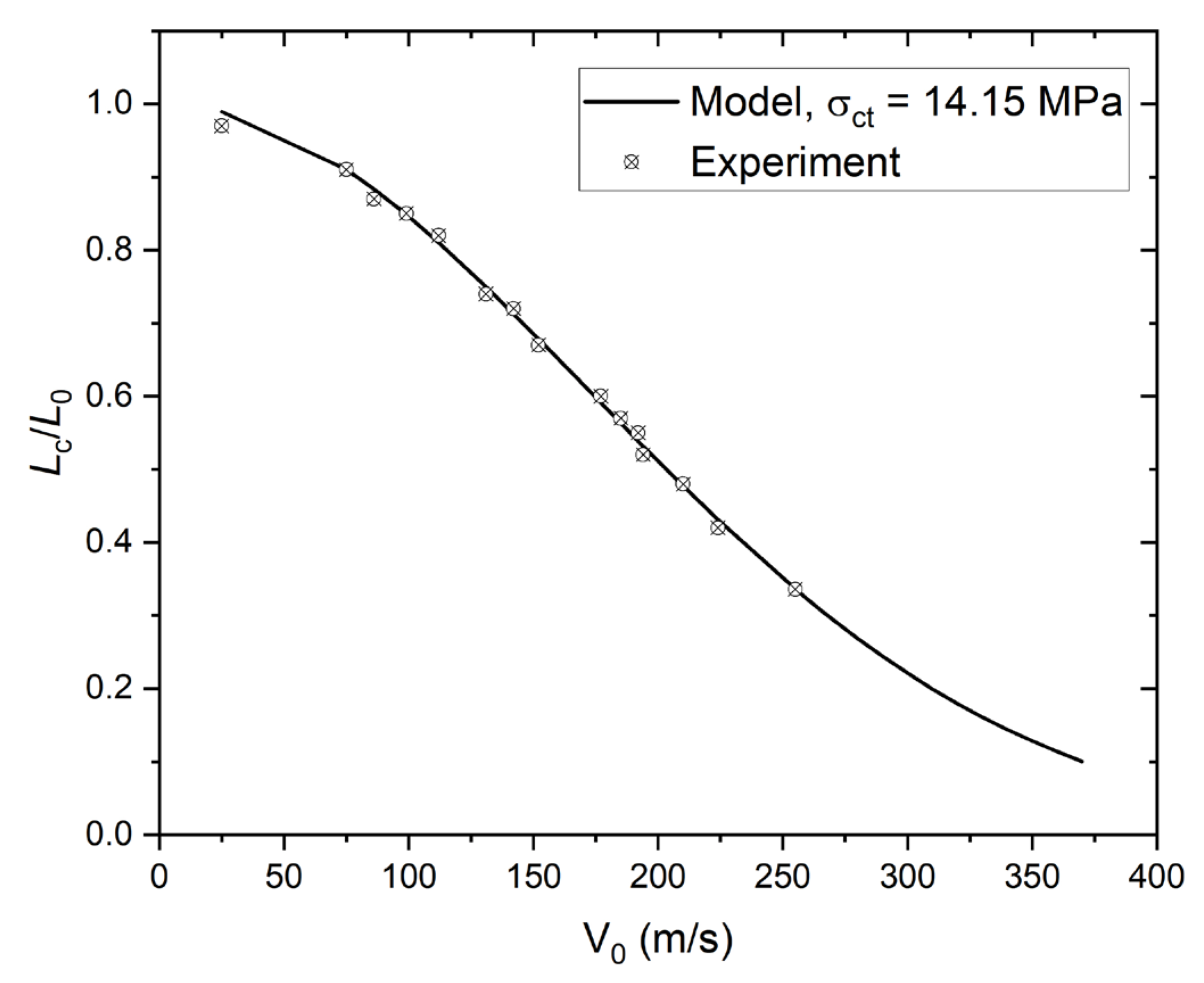
It can be observed that the length of the recovered sample decreases exponentially with increasing velocity of the sample. The length of the recovered sample can be determined using Equation (1) [17].
L c = L 0 exp ρ a ρ 0 V 0 2 2 ρ a ρ 0 σ c r
where L0 denotes the initial length of the foam specimen; ρa and ρ0 represent the densities of the foam and aluminum, respectively; V0 is the velocity of the rod; and σcr refers to the plateau stress. Equation (1) is derived under the assumption that the critical stress, σcr, remains independent of impact velocity and strain rate. Figure 6 presents the dimensionless the length of the recovered sample as a function of impact velocity for various values of σcr, with foam density held constant at ρ0 = 0.468 g/cm3. The experimentally measured value of Lc/L0 can then be plotted as a function of impact velocity. Figure 7 shows the experimentally measured values of Lc/L0 as a function of impact velocities. The plateau stress was determined to be 14.15 MPa, which is derived from our previous work [29].

4. Numerical Results and Discussion

4.1. Numerical Simulation Method

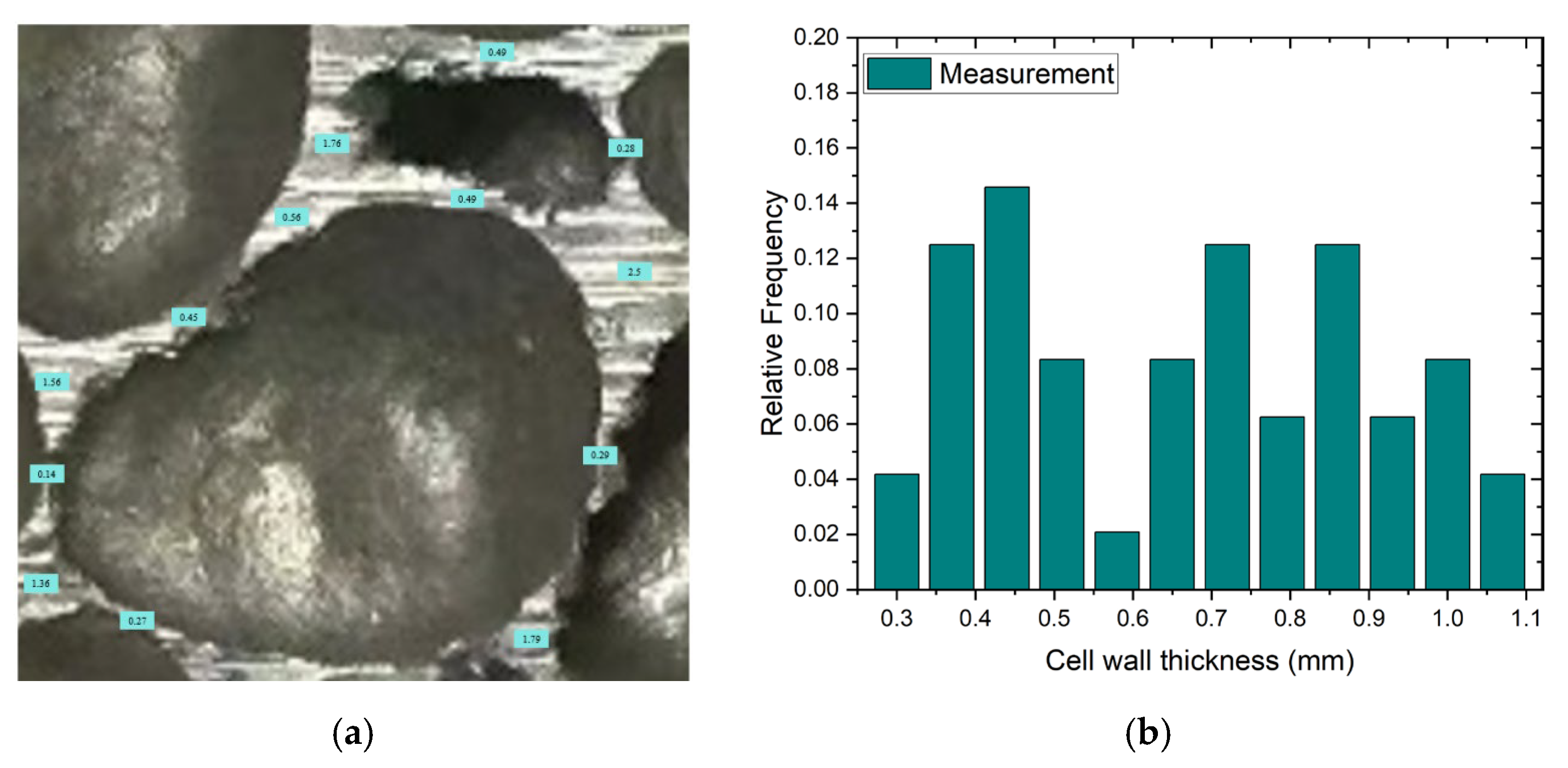
Figure 8a presents representative 2D pore size distributions corresponding to various cell diameters, while Figure 8b illustrates that the measured cell diameters closely follow a log-normal distribution with an average diameter of 6.6 mm. In Figure 9a, several images display the cell wall thicknesses, which also demonstrate an approximately lognormal distribution with a mean thickness of 0.6 mm, as shown in Figure 9b. The statistical characteristics of both cell diameters and wall thicknesses significantly influence the accuracy of the finite element simulation model, highlighting the importance of thorough statistical evaluation of cellular structures.
To simulate the geometric morphology of aluminum foam and establish a meso-scale finite element model that accurately reflects the cell size distribution, this study adopts a method analogous to the actual industrial fabrication process of metallic foams—constructing the model through the generation of a Voronoi diagram. To accurately reflect the cell size distribution and spatial topological characteristics, the Laguerre–Voronoi tessellation (LVT) algorithm [30] is applied to adjust the positions and sizes of internal pores. Wejrzanowski et al. [31] demonstrated that the LVT model is useful in simulating the geometrical characteristics of the foam structure, and the statistical distribution of the simulated pores is similar to that of the actual experimental results.
The primary steps of the algorithm for generating three-dimensional LVT model are as follows:
(1) A set of randomly distributed, densely packed spheres C = C 1 , C 2 , , C n is mapped to a corresponding set of 4D points P * = C 1 , C 2 , , C n . Let (x, y, z) denote the center coordinates of sphere Ci and ri denote its radius. The coordinates of the transformed point P* are then defined as ( x i , y i , z i , x i 2 + y i 2 + z i 2 r i 2 ) .
(2) The Qhull program computes the convex hull of the set P* and identifies its lower facets.
(3) Each face fi consists of 4D points. Given that these points are denoted by P r * , P s *   P t * and P u * , the coordinates of the vertices of the Laguerre cell ( X i , Y i , Z i ) can be computed using Equation (2).
2 x r 2 y r 2 z r 1 2 x s 2 y s 2 z s 1 2 x t 2 y t 2 z t 1 2 x u 2 y u 2 z u 1 X i Y i Z i W i = x r 2 + y r 2 + z r 2 r r 2 x s 2 + y s 2 + z s 2 r s 2 x t 2 + y t 2 + z t 2 r t 2 x u 2 + y u 2 + z u 2 r u 2
(4) We collect all vertices derived from faces that share the same point P*. These vertices collectively define the Laguerre cell associated with the sphere Ci. By computing the convex hull of these vertices, we obtain the topological structure of the Laguerre cell.
(5) Perform step (4) for all points P*, and hierarchically store the geometric and topological data associated with vertices, edges, faces, and elements.
(6) Based on the topological information derived from Equation (2), the geometric model of the Voronoi mesh is constructed in Free CAD using a Python 3.13-based scripting approach. The modeling process starts with generating vertices, proceeds by connecting them into edges, and concludes with forming enclosed cell faces through shell features.
Figure 10 illustrates the procedure for generating the LVT model. A generative model was ultimately developed, and a schematic representation of the four-step process is presented in Figure 11. Figure 12 displays the two-dimensional and three-dimensional Laguerre grids constructed via random close packing.

4.2. Numerical Setup

To prevent the formation of poorly shaped or highly distorted cells, short edges and small faces below a specified threshold are removed, and the aspect ratio of all cell walls is maintained within the range of 1/15 to 1/30. Model analysis reveals that the cumulative area of removed edges and faces constitutes less than 0.001% of the total surface area. Thus, their removal does not significantly compromise the structural integrity or affect the overall stiffness of the model.
In the numerical simulation, the Johnson–Cook constitutive model is employed to characterize the mechanical behavior of the aluminum foam matrix. The corresponding stress–strain relationship is expressed as follows [32]:
σ = [ A + B ( ε p l ) n ] [ 1 + C ln ( ε ˙ p l ε ˙ 0 ) ] ( 1 T * m )
where A, B, n, and c are all material parameters, ε p l and ε ˙ p l are the plastic strain and plastic strain rate, respectively, ε ˙ 0 is the reference strain rate, and T is the temperature. The failure criterion of the Johnson–Cook constitutive model is:
D J C = ε e q ε D p l
ε D p l = [ D 1 + D 2 exp ( D 3 σ H σ e q ) ] [ 1 + D 4 ln ( ε ˙ p l ε ˙ 0 ) ] [ 1 + D 5 T * ]
where D1, D2, D3, D4 and D5 are also material parameters, ε e q is the equivalent strain, σ H is hydrostatic pressure, and σ e q is the equivalent stress. The parameters of the Johnson–cook model are shown in Table 2.
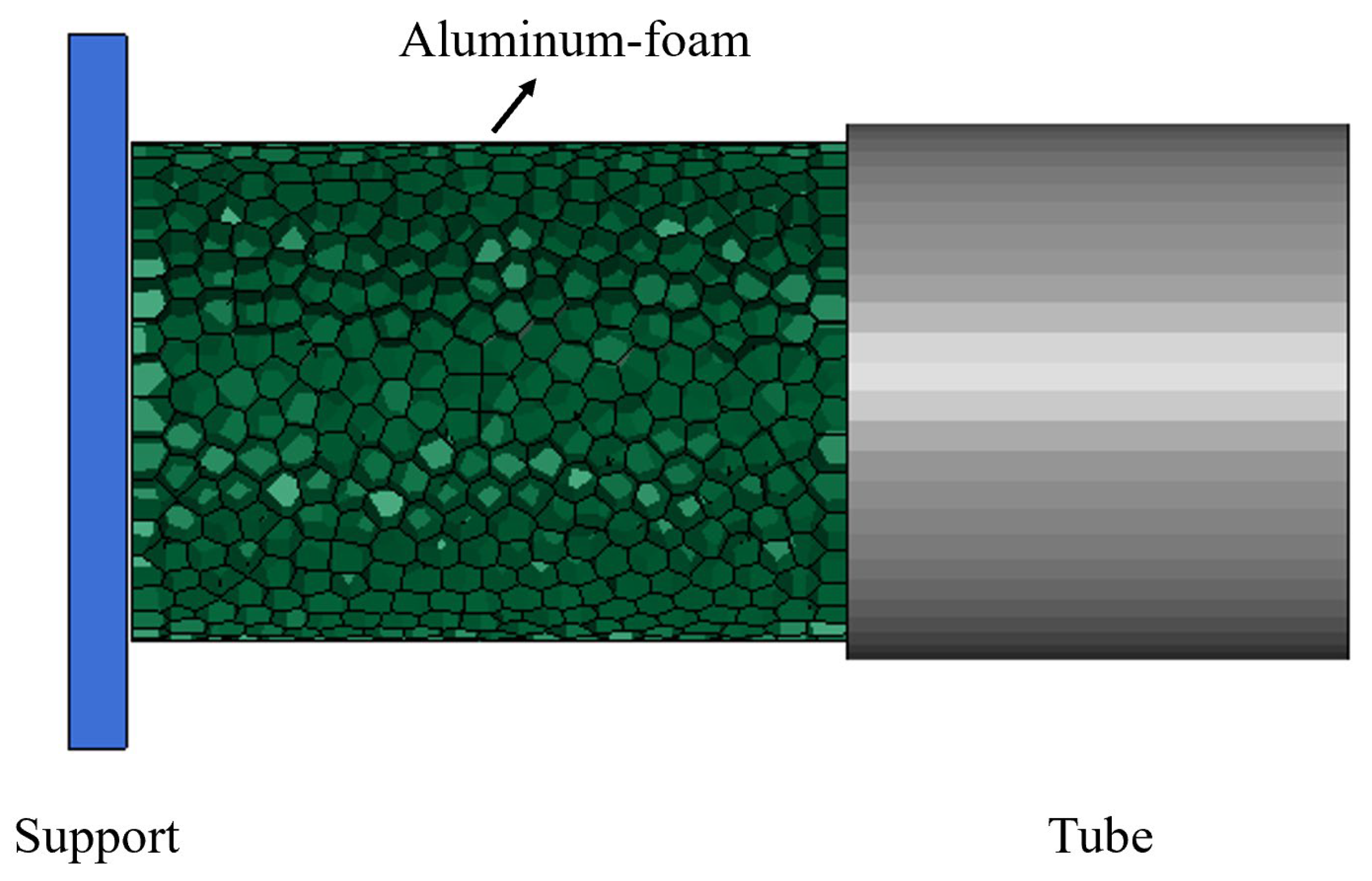
Finite element models of the projectile, sabot, and target plate were developed using LS-DYNA in conjunction with Hyper Mesh, as shown in Figure 13. The projectile has a diameter of 70 mm and a length of 100 mm. The sabot features an outer diameter of 75 mm, an inner diameter of 70 mm, and a length of 80 mm. The target plate is square with a side length of 100 mm and a thickness of 8 mm. To investigate the influence of loading speed on the material’s mechanical response, simulations were conducted at various impact velocities. For computational efficiency, the target plate was modeled as a rigid body with full constraints. The projectile was initially positioned 1 mm above the center of the target plate, with a constant velocity uniformly applied to its base in the direction of loading. The AUTOMATIC_NODES_TO_SURFACE contact algorithm is used to model interactions involving aluminum foam, while the AUTOMATIC_SURFACE_TO_SURFACE algorithm is employed for all other contact interfaces. The dynamic and static friction coefficients are set to 0.03 and 0.02, respectively. To reduce computational cost, a reduced-integration shell element formulation is employed for the aluminum foam, while the target plate and sabot are modeled using 3D solid elements with hourglass control.

4.3. Validation of Numerical Simulations

A grid convergence study was conducted for element sizes of 0.1 mm, 0.2 mm, and 0.3 mm. Figure 14 shows the peak pressure and maximum acceleration corresponding to the different mesh sizes. The peak pressure and maximum acceleration typically reach a convergence point when the mesh size is set to 0.2 mm. By taking into account the balance between computational efficiency and precision, we opted for a mesh size of 0.2 mm in subsequent simulations. To further examine the influence of the friction coefficient on the simulation results, a sensitivity analysis was conducted to assess the robustness of the model under varying friction coefficient values. The dynamic friction coefficient was varied between 0.015 and 0.045, while the static friction coefficient ranged from 0.01 to 0.03. Numerical simulations were carried out at an impact velocity of 255 m/s. Changes in key output parameters—namely peak stress, strain energy, recovered sample length, and deformation mode—varied by less than 5%, demonstrating that the simulation results are stable and largely unaffected by variations in the assumed friction coefficients.
Figure 15 shows the relationship between strain energy, dynamic peak stress and impact velocity. As the impact velocity increases from 25 m/s to 255 m/s, the strain energy rises from approximately 0.05 kJ to approximately 5.8 kJ. The results demonstrate that strain energy increases substantially with higher impact velocity, following a clear linear trend. As the impact velocity increases from 25 m/s t0.o 255 m/s, the dynamic peak stress rises from approximately 24 MPa to 140 MPa. The dynamic peak stress increases with increasing impact velocity, albeit at a rate lower than that of the strain energy. This linear relationship indicates that higher impact velocities lead to increased energy absorption by the material, along with a proportional rise in stress response. The rise in strain energy further confirms that the amount of energy absorbed during impact escalates with increasing impact velocity. This is because the material exhibits more pronounced deformation and failure under high-speed impact, leading to greater energy absorption and dissipation. The corresponding increase in strain energy further indicates the material’s enhanced capacity to absorb energy during the impact process. The increase in dynamic peak stress indicates that the material experiences higher stress levels under high-speed impact loading. This is due to the distinct stress wave propagation and energy absorption mechanisms within the material under high-speed impact, which result in a more pronounced stress response. The increase in dynamic peak stress further indicates the evolution of material strength and stiffness under high-speed impact conditions.
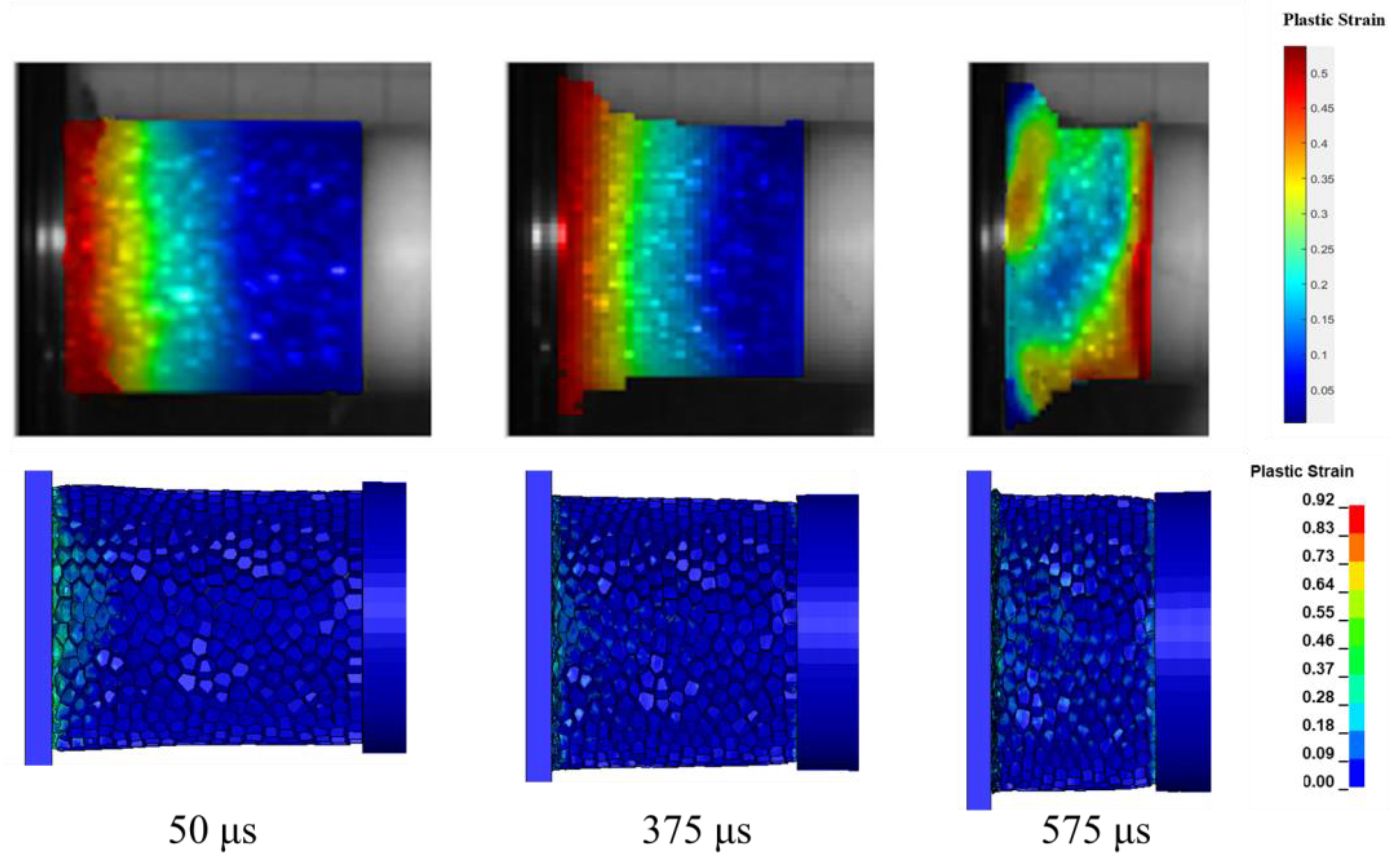
Figure 16 presents a comparison of strain distributions between the Taylor experiment and the meso-scale finite element numerical simulation under the velocity of 131 m/s. The strain distribution trends from both the experimental and simulation results are in good agreement at all time points, demonstrating that the numerical model effectively captures the strain evolution observed in the experiment. The strain initiates at the central region of the specimen and propagates outward toward the edges, indicating that the impact load is transmitted radially from the center to the periphery. As time progresses, strain gradually accumulates, which reflects the progressive plastic deformation and energy absorption characteristics of the material under impact loading. The close consistency between the simulation and experimental results confirms that the meso-scale finite element model is capable of accurately predicting the strain behavior of aluminum foam subjected to impact loads.

4.4. Dynamic Impact Process

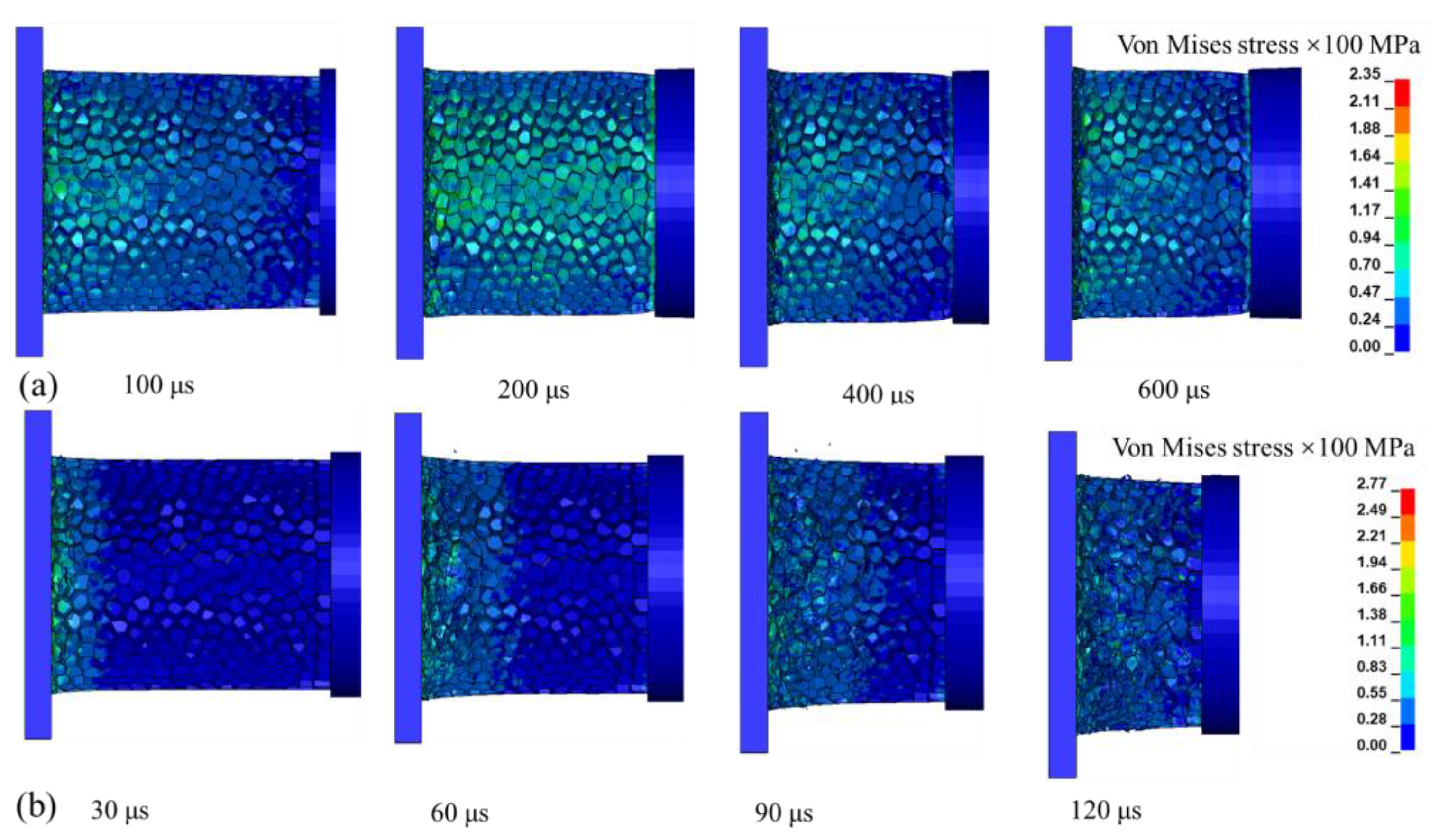
Figure 17 illustrates the mesoscopic deformation patterns of aluminum foam at medium and high impact velocities. It can be observed that under medium-speed impact, stress develops at both the front and rear ends of the specimen, whereas under high-speed impact, stress is predominantly concentrated at the front end. In medium-speed scenarios, the impactor contacts the target plate, generating an initial compressive stress and initiating a compressive wave that propagates through the specimen. In contrast, under high-speed impact, rapid compression occurs at the front end, leading to a sharp increase in local stress. The impact energy is quickly dissipated as the foam undergoes compaction. Due to the limited time available for stress propagation, deformation does not fully extend to the rear end, leading to a phenomenon known as stress lag. Furthermore, the progressive densification of the material hinders the formation and propagation of the compressive wave. Since the impact velocity exceeds the shock wave propagation speed within the material, the rear end experiences minimal stress, which accounts for the localized stress distribution observed only at the front end.
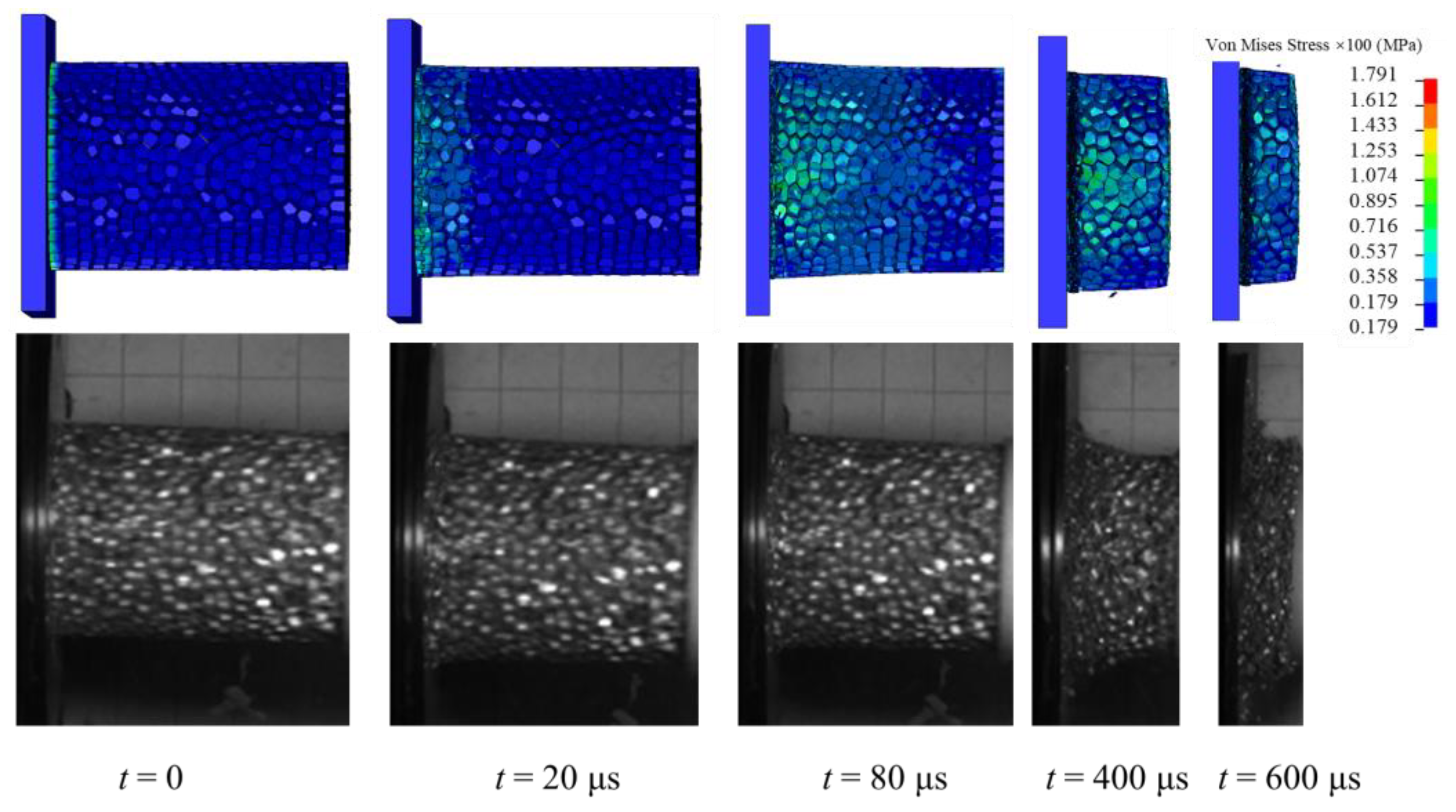
Figure 18 compares the deformation mode of aluminum foam at an impact velocity of 255 m/s between fine finite element numerical simulations and experimental results. The pores of the aluminum foam progressively collapsed, buckled, and fractured in a layer-by-layer manner, while the stress remained nearly constant over a broad strain range, enabling significant energy absorption during this phase.
Figure 19 presents the axial stress history curves at multiple locations within the aluminum foam. From the initial stage of stress wave propagation, the measured wave speed in aluminum foam is determined to be 3448 m/s. It is evident that the stress wave propagation velocity in aluminum foam is considerably lower than that in solid aluminum, which exhibits a value of approximately 5200 m/s. The propagation path of the stress wave is governed by the network structure of the cell walls. As the wave propagates, it continuously exerts work on the cell walls, leading to bending and buckling deformations. In Taylor tests, a distinct shock wave front is observed, representing the interface where the material undergoes transition from a porous to a fully densified state. Ahead of the wavefront lies the undeformed original foam structure, while behind it is the compacted region in which cell walls have collapsed, fractured, and undergone consolidation. The fracture and failure of cell walls occur predominantly within the shock wave front. The propagation of the shock wave front fundamentally involves the progressive engulfment and compaction of upstream undeformed foam, driven by the collapse and fragmentation of cell walls. Thus, cell wall failure is crucial for the stable advancement of the shock wave front.
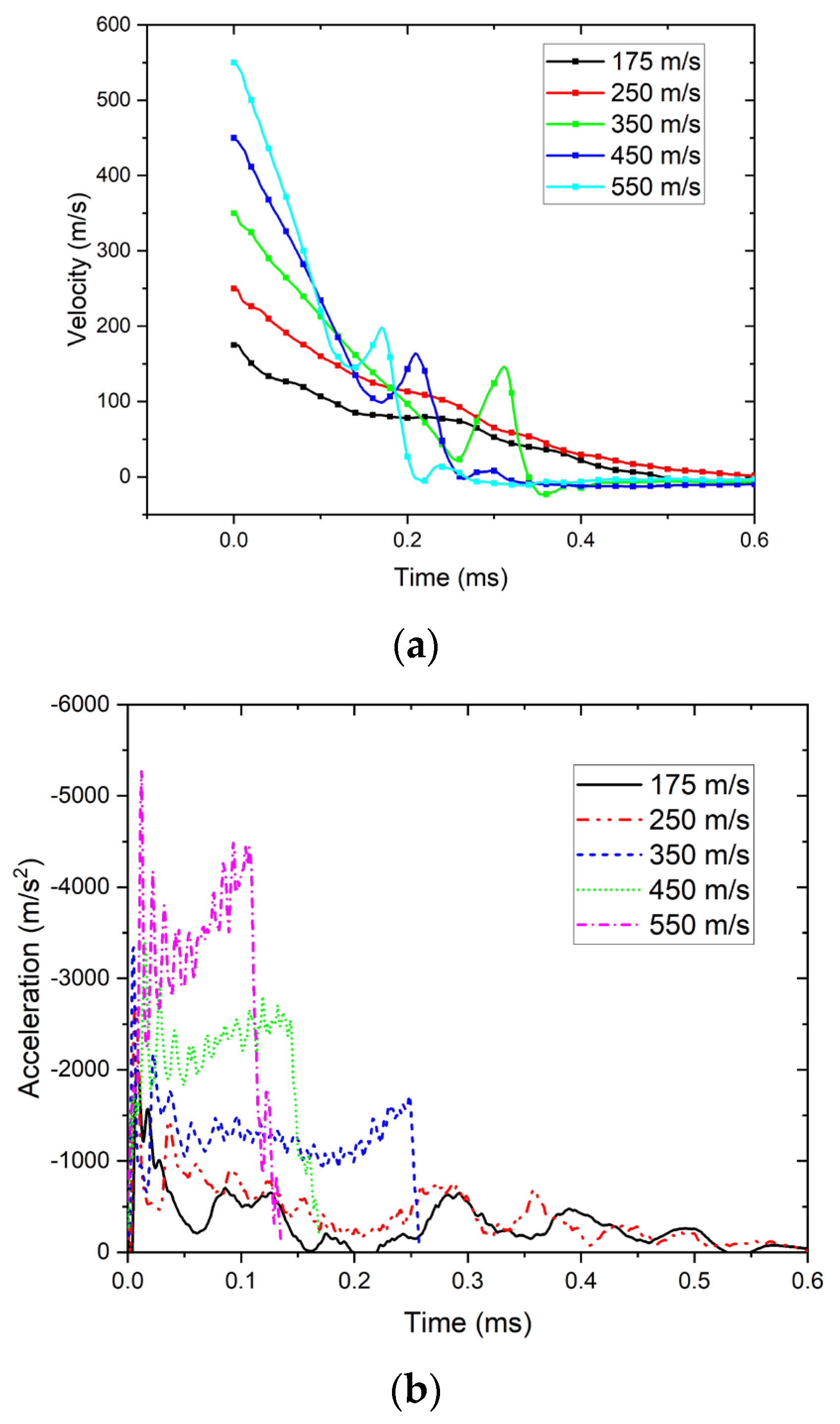
Figure 20 presents the velocity and acceleration history curves of aluminum foam under impact at different velocities. As the impact velocity increases, the peak acceleration gradually rises and the pulse width of acceleration gradually decreases. This indicates that under low-strain-rate conditions, aluminum foam has excellent energy absorption capacity and sufficient deformation potential. Under high-speed impact conditions, the peak acceleration increases more rapidly with increasing velocity, indicating enhanced material stiffness and greater resistance to deformation at elevated strain rates. Due to the porous structure and microscopic characteristics of aluminum foam materials, shock wave propagation in such media is dispersed, resulting in a reduced wave speed. As the impact velocity increases, the density of the localized compaction zone rises rapidly, which weakens the wave dispersion effect and significantly enhances the shock wave propagation velocity. Aluminum foam materials demonstrate notable strain rate sensitivity. As impact velocity increases, a substantial inertial effect arises within the material, triggering rapid collapse of the cellular structure. The internal stress field fails to equilibrate in a timely manner, leading to localized stress concentration. The higher the impact velocity, the more rapid the cell collapse and the sharper the increase in local stress peaks, leading to a corresponding rise in yield stress with increasing impact velocity.

5. Conclusions

This study presents the results of experimental and numerical investigations on the low- and medium-velocity impact behavior of low-density aluminum foam. The damage characteristics of aluminum foam under varying impact velocities were systematically examined. Taylor impact tests demonstrate that, under low-speed conditions, the material exhibits excellent energy absorption capacity. As the impact velocity increases, both peak stress and dynamic strength increase significantly, accompanied by an expanded strain range. Combined experimental and numerical analyses reveal the complete deformation process—from initial compression and plastic collapse to steady-state compaction—highlighting pore collapse and dynamic compression as the dominant energy dissipation mechanisms. It is concluded that aluminum foam exhibits favorable plastic deformation and energy absorption performance under low-velocity impacts, making it well-suited for use in buffer and protective structural designs. Strategic selection of aluminum foam according to its performance under specific loading conditions can therefore enhance its optimized application in engineering contexts.

Author Contributions

C.F. initiated the project, supervised its progress and wrote this publication. Y.X., conceived and designed the experiments. X.D. manufactured the samples, conducted mechanical testing and documented the results. Y.X. contributed to project planning, and conducted the mechanical analysis. W.L. analyzed the data, and revised and approved the paper. All authors have read and agreed to the published version of the manuscript.

Funding

This work was supported by the National Natural Science Foundation of China (NSFC 11802273, 12372368), the National Key Laboratory of Energetic Materials, and the Natural Science Foundation of Shanxi Province (202303021211142).

Data Availability Statement

The data presented in this study are available on request from the corresponding author. The data are not publicly available due to privacy restrictions.

Acknowledgments

Thanks go to the National Key Laboratory of Land and Air-Based Information Perception and Control (No. A424003) for experiments assistance.

Conflicts of Interest

The authors declare no conflict of interest.

References

  1. Wu, X.W.; Zhang, J.; Zhang, J.X.; He, R.; Liu, Q.M. Low-velocity impact of square conical gradient aluminium foam-filled automobile energy-absorbing boxes. Int. J. Crashworthiness 2024, 29, 330–346. [Google Scholar] [CrossRef]
  2. Casaburo, A.; Petrone, G.; Meruane, V.; Franco, F.; De Rosa, S. The vibroacoustic behaviour of aluminium foam sandwich panels in similitude. J. Sandw. Struct. Mater. 2021, 23, 4170–4195. [Google Scholar] [CrossRef]
  3. Xia, Y.; Wu, C.Q.; Liu, Z.X.; Yuan, Y.M. Protective effect of graded density aluminium foam on RC slab under blast loading—An experimental study. Constr. Build. Mater. 2016, 111, 209–222. [Google Scholar] [CrossRef]
  4. Kumar, R.; Jain, H.; Sriram, S.; Chaudhary, A.; Khare, A.; Ch, V.A.N.; Mondal, D.P. Lightweight open cell aluminum foam for superior mechanical and electromagnetic interference shielding properties. Mater. Chem. Phys. 2020, 240, 122274. [Google Scholar] [CrossRef]
  5. Amsterdam, E.; Onck, P.R.; De Hosson, J.T.M. Fracture and microstructure of open cell aluminum foam. J. Mater. Sci. 2005, 40, 5813–5819. [Google Scholar] [CrossRef]
  6. Guo, Q.; Yao, W.J.; Li, W.B.; Wang, X.M.; Huang, C.Q. Mechanical Properties of Aluminium Foam and Affect Dynamic Strain-Stress Relationship. Sci. Adv. Mater. 2021, 13, 2200–2212. [Google Scholar] [CrossRef]
  7. Ma, C.C.; Lan, F.C.; Chen, J.Q.; Liu, J.; Zeng, F.B. Automobile crashworthiness improvement by energy-absorbing characterisation of aluminium foam porosity. Mater. Res. Innov. 2015, 19, S109–S112. [Google Scholar] [CrossRef]
  8. Novak, N.; Vesenjak, M.; Duarte, I.; Tanaka, S.; Hokamoto, K.; Krstulovic-Opara, L.; Guo, B.Q.; Chen, P.W.; Ren, Z.R. Compressive Behaviour of Closed-Cell Aluminium Foam at Different Strain Rates. Materials 2019, 12, 4108. [Google Scholar] [CrossRef]
  9. Peroni, M.; Solomos, G.; Pizzinato, V. Impact behaviour testing of aluminium foam. Int. J. Impact Eng. 2013, 53, 74–83. [Google Scholar] [CrossRef]
  10. Mukai, T.; Miyoshi, T.; Nakano, S.; Somekawa, H.; Higashi, K. Compressive response of a closed-cell aluminum foam at high strain rate. Scr. Mater. 2006, 54, 533–537. [Google Scholar] [CrossRef]
  11. Li, Z.B.; Chen, R.; Lu, F.Y. Comparative analysis of crashworthiness of empty and foam-filled thin-walled tubes. Thin Wall. Struct. 2018, 124, 343–349. [Google Scholar] [CrossRef]
  12. Qiu, Q.Z.; Wang, H.T.; Ma, W.T. Experimental and Analytical Study on Multiscale Cushioning and Energy Absorption of Aluminum Foam at Different Strain Rates. Appl. Sci. 2025, 15, 2638. [Google Scholar] [CrossRef]
  13. Shi, S.Q.; Kang, J.G.; Sui, S.B. Experimental Study of Quasi-static and Dynamic Compressive Property of Close-cell Aluminum Foam. Rare Metal Mat. Eng. 2011, 40, 150–154. [Google Scholar]
  14. Liu, H.; Cao, Z.K.; Luo, H.J.; Shi, J.C.; Yao, G.C. Performance of closed-cell aluminum foams subjected to impact loading. Mat. Sci. Eng. A Struct. 2013, 570, 27–31. [Google Scholar] [CrossRef]
  15. Bin Muhit, I.; Shim, C.S.; Yun, N.R.; Park, S.D. Effect of Strain Rate on Impact Behavior of Aluminum Foam. KSCE J. Civ. Eng. 2019, 23, 4852–4863. [Google Scholar] [CrossRef]
  16. Taylor, G.I. The use of flat-ended projectiles for determining dynamic yield stress I. Theoretical considerations. Proc. R. Soc. 1948, 194, 289–299. [Google Scholar]
  17. Lopatnikov, S.L.; Gama, B.A.; Jahirul Haque, M.; Krauthauser, C.; Gillespie, J.W.; Guden, M.; Hall, I.W. Dynamics of metal foam deformation during Taylor cylinder–Hopkinson bar impact experiment. Compos. Struct. 2003, 61, 61–71. [Google Scholar] [CrossRef]
  18. Wang, B.; Zhang, J.; Lu, G. Taylor impact test for ductile porous materials—Part 2: Experiments. Int. J. Impact Eng. 2003, 28, 499–511. [Google Scholar] [CrossRef]
  19. Lu, G.; Wang, B.; Zhang, T. Taylor impact test for ductile porous materials—Part 1: Theory. Int. J. Impact Eng. 2001, 25, 981–991. [Google Scholar] [CrossRef]
  20. Lee, J. Estimation of High Speed Mechanical Properties for Metallic Materials under Impact and Blast Load Using Taylor Impact Test. Trans. KSME A 2022, 46, 859–867. [Google Scholar] [CrossRef]
  21. Wlodarczyk, E.; Sarzynski, M. Experimental analysis of density and compressive strain of porous metal with the use of Taylor test. Arch. Mech. 2014, 66, 245–256. [Google Scholar]
  22. Huang, B.; Lin, L.; Xu, T.L.; Xiao, X.K.; Wang, J.Q. A Study of the Dynamic Mechanical Properties of Q460D Steel. Metals 2023, 13, 1609. [Google Scholar] [CrossRef]
  23. Kovácik, J. Correlation between elastic modulus, shear modulus, Poisson’s ratio and porosity in porous materials. Adv. Eng. Mater. 2008, 10, 250–252. [Google Scholar] [CrossRef]
  24. Hao, G.L.; Xu, Q.P.; Wang, H.; Li, X.Y. Effect of pore structure on mechanical properties of porous TiAl. Mater. Sci. Technol. 2016, 32, 1592–1596. [Google Scholar] [CrossRef]
  25. Zhao, H.X.; Li, L.H.; Ding, S.; Liu, C.X.; Ai, J.Y. Effect of porous structure and pore size on mechanical strength of 3D-printed comby scaffolds. Mater. Lett. 2018, 223, 21–24. [Google Scholar] [CrossRef]
  26. Zhang, X.Y.; Tang, L.Q.; Liu, Z.J.; Jiang, Z.Y.; Liu, Y.P.; Wu, Y.D. Yield properties of closed-cell aluminum foam under triaxial loadings by a 3D Voronoi model. Mech. Mater. 2017, 104, 73–84. [Google Scholar] [CrossRef]
  27. Wang, E.R.; Cai, J.J.; Huo, X.T.; Guo, X. Multiaxial yield behavior of transversely isotropic closed-cell aluminum foams. Int. J. Solids Struct. 2025, 314, 113322. [Google Scholar] [CrossRef]
  28. Jia, R.; Zhao, G.P. Influence of Cell Wall Material and Cell Numbers on Mechanical Properties of Closed-Cell Aluminum Foams. J. Mater. Eng. Perform. 2025, 34, 10378–10386. [Google Scholar] [CrossRef]
  29. Xiao, Y.; Liu, H.; Dong, X.; Fan, C.; Zou, Y.; Han, Y.; Sun, Y. Effect of cell diameter variations on the mechanical behavior of aluminum foams: Experiments and modeling. Mater. Today Commun. 2024, 3, 109090. [Google Scholar] [CrossRef]
  30. Falco, S.; Jiang, J.; De Cola, F.; Petrinic, N. Generation of 3D polycrystalline microstructures with a conditioned Laguerre-Voronoi tessellation technique. Comp. Mater. Sci. 2017, 136, 20–28. [Google Scholar] [CrossRef]
  31. Wejrzanowski, T.; Skibinski, J.; Szumbarski, J.; Kurzydlowski, K.J. Structure of foams modeled by Laguerre–Voronoi tessellations. Comp. Mater. Sci. 2013, 67, 216–221. [Google Scholar] [CrossRef]
  32. Flores-Johnson, E.A.; Shen, L.; Guiamatsia, I.; Nguyen, G.D. Numerical investigation of the impact behaviour of bioinspired nacre-like aluminium composite plates. Compos. Sci. Technol. 2014, 96, 13–22. [Google Scholar] [CrossRef]
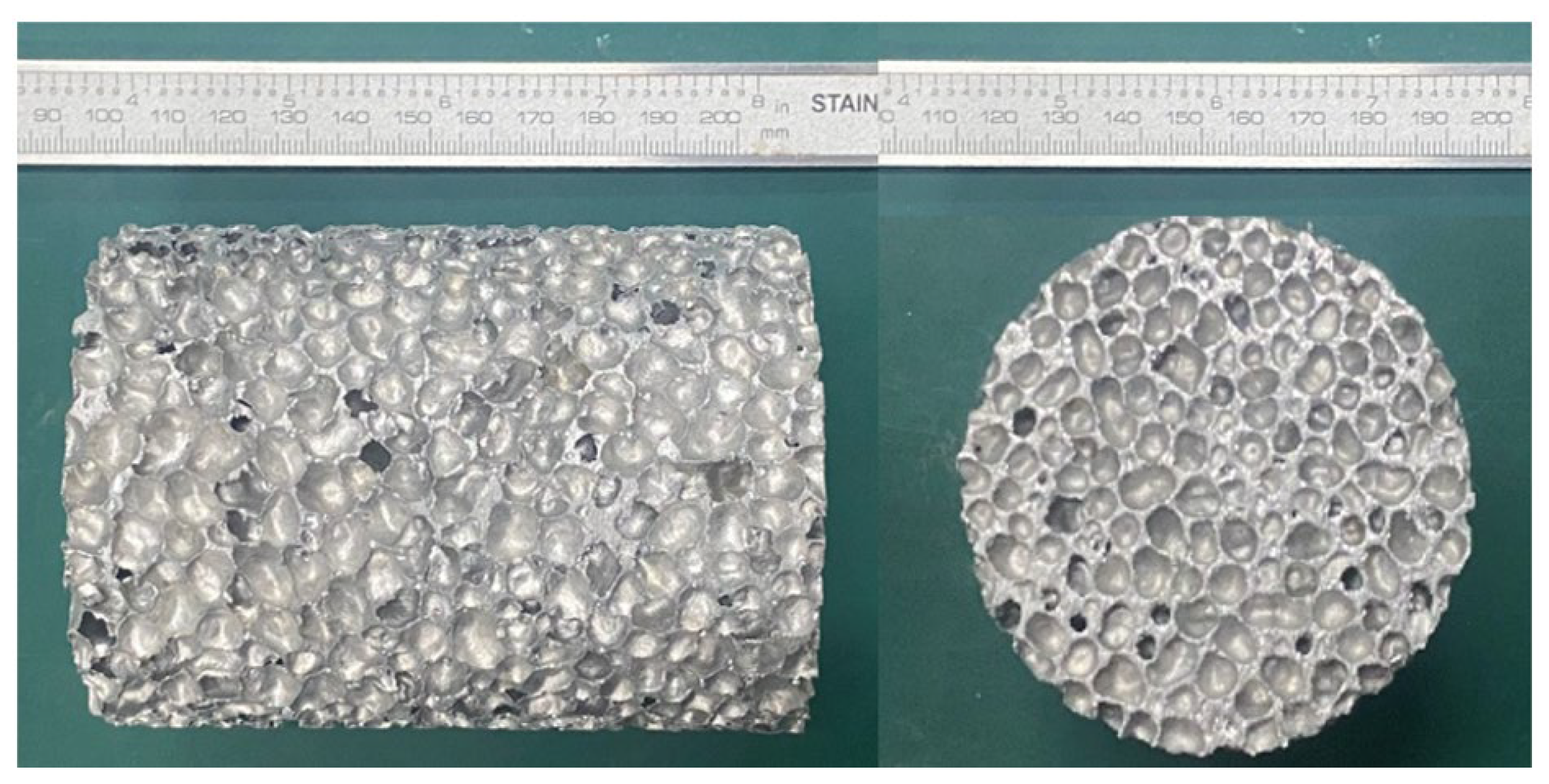
Figure 1. Aluminum foam specimens: right view and front view.
Metals 15 01313 g001
Figure 2. Schematic diagram of the Taylor test.
Metals 15 01313 g002
Figure 3. Schematic illustration of the dynamic loading experimental setup and the light gas gun.
Metals 15 01313 g003
Figure 4. Cross-sections collapsed of foam specimens.
Metals 15 01313 g004
Figure 5. Specimen dynamic impact process at the velocity of (a) 131 m/s and (b) 255 m/s.
Metals 15 01313 g005
Figure 6. Dimensionless critical un-collapsed length as a function of impact velocity and critical stress.
Metals 15 01313 g006
Figure 7. Experimental dimensionless length of the recovered sample as a function of impact velocity and Equation (1) fit.
Metals 15 01313 g007
Figure 8. (a) Cell sizes; (b) Cell size measurements and their probability distribution curve.
Metals 15 01313 g008
Figure 9. (a) Cell wall thicknesses; (b) cell wall thickness measurements and their probability distribution curve.
Metals 15 01313 g009
Figure 10. Process used to generate the Laguerre–Voronoi tessellation (LVT) model.
Metals 15 01313 g010
Figure 11. Schematic of the algorithm used for foam structure generation: (a) cell-core distribution; (b) cell-diameter distribution; (c) modelling considering cell diameter; (d) local enlarged view.
Metals 15 01313 g011aMetals 15 01313 g011b
Figure 12. (a) Two-dimensional Laguerre subdivision surfaces and incircles; (b) Three-dimensional LVT model.
Metals 15 01313 g012
Figure 13. Finite element model setup.
Metals 15 01313 g013
Figure 14. Size convergence analysis: (a) convergence of peak stress; (b) convergence of Maximum acceleration.
Metals 15 01313 g014
Figure 15. Relationship between strain energy, dynamic peak stress and impact velocity.
Metals 15 01313 g015
Figure 16. Comparison between macroscopic experiments and simulations of strain under the velocity of 131 m/s.
Metals 15 01313 g016
Figure 17. Fine-scale finite element numerical simulation of deformation patterns under different impact velocities: (a) 175 m/s; (b) 550 m/s.
Metals 15 01313 g017
Figure 18. Comparison of fine finite element numerical simulations and experimental results for the deformation mode of aluminum foam at 255 m/s.
Metals 15 01313 g018
Figure 19. Axial stress history curves at various positions within the aluminum foam: (a) 255 m/s; (b) 550 m/s.
Metals 15 01313 g019
Figure 20. The velocity (a) and acceleration (b) of aluminum foam under varying impact velocities.
Metals 15 01313 g020
Table 1. The peak impact pressure, length, maximum diameter, and mass loss of the recovered samples.
Sample No.Velocity (m/s)Maximum Pressure (MPa)Length of the Specimen (mm)Length of the Recovered Sample (mm)Maximum Diameter of the Recovered Sample (mm)Mass Loss (g)
1752410091.378.312.0
2955410084.877.518.4
31316010075.076.322.5
417711010060.472.564.3
519412210055.572.472.3
621012510052.468.769.5
725514010033.665.856.4
Table 2. Parameters of the Johnson–Cook model [32].
ParametersA/MPaB/MPaCnm ε ˙ /s−1Tr/KTm/K
Value5204770.0010.5215 × 10−4293893
ParametersD1D2D3D4D5ρ/kg·m−3E/GPaν
Value0.0960.049−3.4650.0161.0992700700.3
Disclaimer/Publisher’s Note: The statements, opinions and data contained in all publications are solely those of the individual author(s) and contributor(s) and not of MDPI and/or the editor(s). MDPI and/or the editor(s) disclaim responsibility for any injury to people or property resulting from any ideas, methods, instructions or products referred to in the content.