Article

Influence of Ball Burnishing Path Strategy on Surface Integrity and Performance of Laser-Cladded Inconel 718 Alloys

1
UniSA STEM, University of South Australia, Mawson Lakes, SA 5095, Australia
2
Faculty of Science and Technology, Federal University of Goiás—UFG, Aparecida de Goiânia Campus, Municipal Road, Block and Lot Area 04, Aparecida de Goiânia 74971-45, GO, Brazil
3
Future Industries Institute, University of South Australia, Mawson Lakes, SA 5095, Australia
4
Laserbond Ltd., Cavan, SA 5094, Australia
*
Author to whom correspondence should be addressed.
Metals 2025, 15(11), 1190; https://doi.org/10.3390/met15111190 (registering DOI)
Submission received: 23 September 2025 / Revised: 21 October 2025 / Accepted: 22 October 2025 / Published: 26 October 2025
(This article belongs to the Special Issue Metal 3D Printing Techniques for Biomedical Applications)

Abstract

This study investigates the influence of ball burnishing (BB) path strategies on the surface integrity and functional performance of laser-cladded Inconel 718. Three BB strategies—(1) BB-Longitudinal, (2) BB-Transverse, and (3) BB-Crosshatch—relative to the laser scan trajectory were evaluated and compared against ground surfaces as a baseline. Post-processing BB treatment were demonstrated to be effective in modifying the subsurface layer of the cladded Inconel 718 material, extending to depths of up to 100 µm, increasing dislocation density by over 2.5 times, and enhancing hardness from 260 HV5 (ground) to as high as 461 HV5. These microstructural improvements led to significant gains in corrosion and impact resistance, despite a rise in surface roughness from Ra 0.35 µm (ground) to up to 2.38 µm for BB-Longitudinal surfaces. Impact testing revealed up to 35% reduction in indentation volume, particularly with BB-Transverse and BB-Crosshatch strategies. Nonetheless, sliding wear tests did not confirm improvements in wear resistance, as wear depths exceeded the hardened layer and abrasive wear remained dominant. Electrochemical testing in 3.5 wt.% NaCl solution showed a positive shift in corrosion potential (Ecorr) exceeding 200 mV compared to the ground condition, indicating reduced corrosion susceptibility for BB-Longitudinal condition. Among the tested strategies, BB-Transverse offered the most balanced enhancements, highlighting the complex interplay between laser cladding heterogeneities and post-processing response in optimizing surface and mechanical properties of Inconel 718 claddings.

1. Introduction

Inconel 718 is a nickel-chromium-based superalloy engineered for structural applications that demand high mechanical strength, corrosion resistance, and thermal stability at elevated temperatures—up to approximately 700 °C. These properties, along with its resistance to oxidation, make it a material of choice in aerospace, energy, and other high-performance industries [1]. The alloy’s exceptional performance is attributed to its complex composition, including niobium, molybdenum, titanium, and aluminum, which promote precipitation hardening and microstructural stability under demanding service conditions [2].
Among various manufacturing techniques, laser cladding—an additive manufacturing (AM) process within the broader category of Directed Energy Deposition (DED)—has gained prominence for applying Inconel 718 coatings to restore or enhance surface functionality. This process forms a strong metallurgical bond by melting and fusing Inconel 718 powder onto a substrate using a high-energy laser beam, enabling precise geometries and material efficiency. However, it may also introduce residual stresses, porosity, and irregular surface morphology, which can compromise mechanical performance, particularly under cyclic or elevated-temperature loading [3,4]. Moreover, laser-based DED processes impart unique microstructural characteristics—such as large grains and reduced grain boundary density—that significantly influence post-processing behavior and surface integrity [5]. To address these challenges, post-processing techniques are essential to improve surface quality and ensure the functional reliability of AM-fabricated or repaired components.
Mechanical surface treatments—including barrel finishing, shot peening, ultrasonic impact treatment, and laser shock peening—have demonstrated effectiveness in enhancing the surface condition and mechanical performance of Inconel 718 following laser-based AM processes. For example, ultrasonic impact treatment has achieved up to a 57.4% reduction in surface roughness, while shot peening has increased microhardness by 66.5% in selectively laser melted Inconel 718 [6]. Similarly, laser shock peening introduces beneficial compressive residual stresses to AM-fabricated Inconel 718, improving fatigue life and wear resistance [7]. Recent studies also highlight that the microstructural differences inherent to laser-processed Inconel 718, when paired with optimized machining strategies such as multi-pass wire electro-discharge machining (WEDM), can significantly reduce recast layer formation and enhance surface integrity [5].
Among these techniques, ball burnishing (BB) has emerged as a cost-effective, non-abrasive method that enhances surface and subsurface properties through controlled plastic deformation. By applying a hard spherical tool under pressure, BB induces compressive residual stresses, refines subsurface grain structure, and increases hardness, leading to improved fatigue, wear, and corrosion resistance in metallic components [8,9,10]. Recent investigations have demonstrated its efficacy on Inconel 718, with optimized parameters yielding notable enhancements in surface integrity [11]. Notably, the directionality of the burnishing path relative to prior machining or deposition operations plays a critical role in determining surface outcomes. Studies suggest that the orientation of BB relative to prior milling paths can significantly affect surface finish, with certain tool paths—such as perpendicular passes—yielding improved results under specific conditions [12]. Similarly, in laser cladding, the orientation of scan tracks has been found to impact mechanical properties, with longitudinal tracks generally producing higher tensile strength than transverse ones due to more favorable grain alignment and thermal gradients [13,14].
Despite the established importance of directionality in each process individually, there is a notable gap in understanding the specific interaction between the directionality of BB paths and the laser scan trajectory in laser-cladded Inconel 718. This gap is particularly significant given the potential for optimizing post-processing strategies to maximize surface integrity and functional performance.
This study addresses this critical gap by systematically investigating the influence of three BB path strategies—longitudinal, transverse, and crosshatch—relative to the laser scan trajectory on the surface integrity and functional performance of laser-cladded Inconel 718. By comparing these strategies against a ground surface baseline, the research aims to identify the optimal burnishing path that maximizes post-processing benefits while mitigating potential drawbacks, such as increased surface roughness.

2. Materials and Methods

2.1. Laser Cladding and Sample Preparation

This study involved laser cladding a 20 mm wide band of Inconel 718 onto a circular hollow section (CHS) mild steel substrate (AS/NZS 1163 Grade C250L0, Adelaide, Australia), measuring 60.3 mm in outer diameter and 4.5 mm in wall thickness. Inconel 718 powder, with a particle size distribution (d10–d90) ranging from 45 to 90 µm, was used as the feedstock. Its chemical composition is presented in Table 1.
Cladding was performed circumferentially using an industrial laser system integrated with a computer numerical control (CNC) controlled platform and a dedicated powder feeding unit. The system was configured in an off-axis arrangement, as schematically illustrated in Figure 1a. In this setup, the powder delivery nozzle was positioned perpendicular to the substrate, while the laser beam was angled obliquely, producing a 4.8 mm spot diameter on the workpiece surface. This configuration facilitated stable melt pool formation and uniform circumferential deposition as the laser and powder head traversed linearly while the cylindrical substrate rotated continuously.
Prior to deposition, the substrate surface was preheated to approximately 200 °C to promote metallurgical bonding and reduce thermal stresses. Then three successive layers of Inconel 718 were deposited, achieving a total clad thickness of approximately 3 mm. Key processing parameters—including laser power, scan speed, and powder feed rate—were held constant throughout the deposition. A 50% overlap ratio between tracks and a fixed nozzle offset were maintained to ensure consistent coverage. A helium–argon gas mixture was employed as the shielding gas, while nitrogen was used as the carrier gas during deposition. Following cladding, all samples were air-cooled to ambient temperature.
To evaluate the cladding process, two combined processing parameters were calculated: specific energy ( E s p e c i f i c ) and powder density ( G ) [15]. These parameters characterize the laser energy absorbed by both the powder and the substrate, and are commonly used to assess the resulting microstructural and mechanical properties of laser-processed Inconel 718 [16]. The parameters are defined by the following expressions:
E s p e c i f i c = P w 2 U r l
G = m ˙ 2 U r l
where P w is the laser power on the substrate, U is the scanning speed, r l is the radius of the laser beam on the substrate, and m ˙ is the powder feed rate. For this study, the calculated values of E s p e c i f i c and G are 34.7 J/mm2 and 0.31 g/mm2, respectively.
A total of 12 rectangular coupons were extracted from the cladded CHS substrate, each measuring approximately 25 × 15 mm. The as-cladded surfaces were initially smoothed by removing 0.5 mm of coupon thickness, followed by fine grinding using a BMT 4080 AH surface grinding machine (BMT, Heidenheim, Germany) equipped with a diamond wheel operating at 1450 rpm. Final passes were performed in 5 μm increments to achieve flat and uniform cladded surface. The grinding process was carried out along the cladding direction under a cooling lubricant to minimize thermal effects. Three of the ground coupons were retained as control specimens, while the remaining were subjected to ball burnishing using various burnishing path strategies. Figure 1b shows the as-cladded CHS substrate and the sectioned coupons.

2.2. Ball Burnishing Experimental

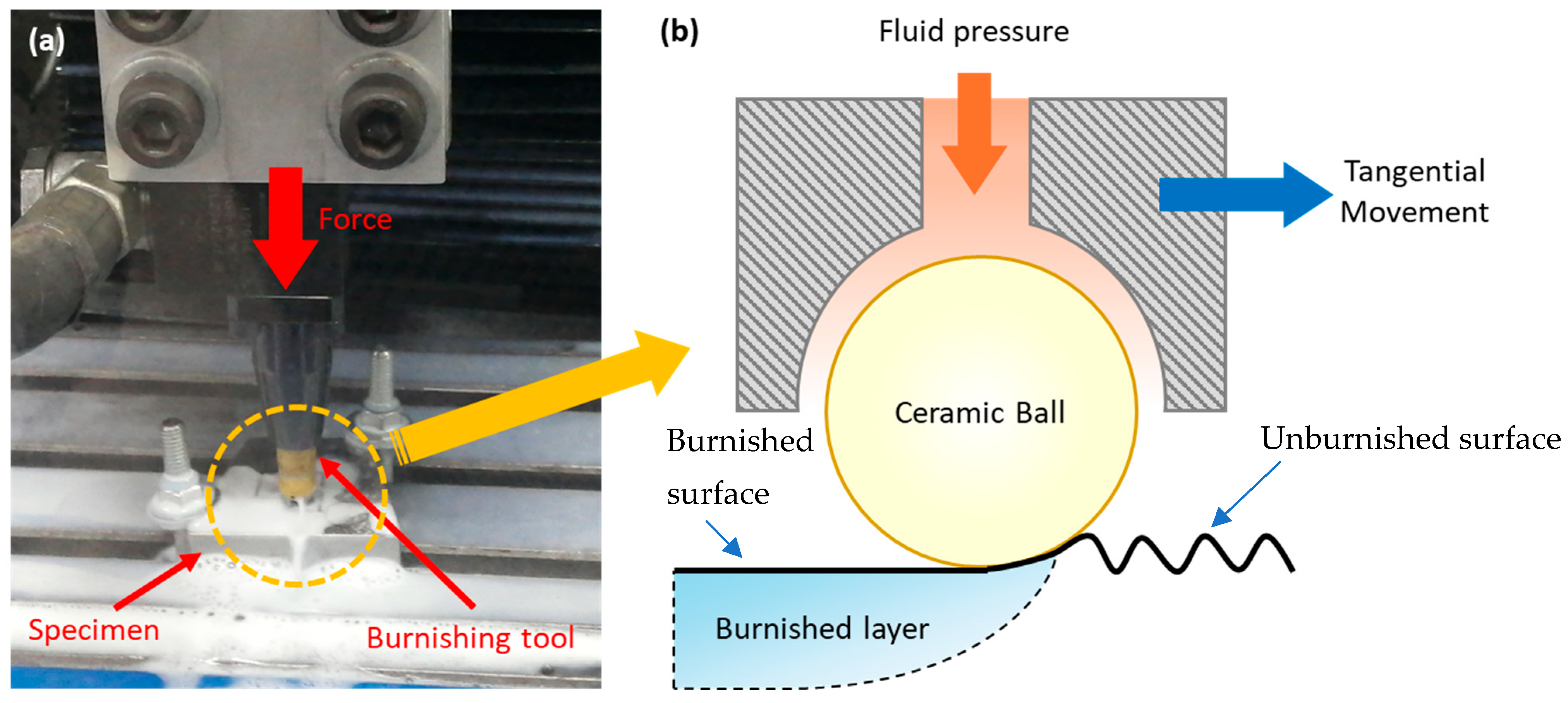
The post-processing BB treatment was carried out using a burnishing tool (Ecoroll HG6-9 E00°, Ecoroll AG, Celle, Germany) fitted with a Si3N4 ceramic ball measuring 6.3 mm in diameter and possessing a hardness of 940 HV. Given the significantly higher hardness of the ball compared to the Inconel 718 surface, it was assumed that the ball would not undergo plastic deformation during the process. The burnishing tool was mounted on the spindle of a CNC milling machine, and a hydraulic pump applied a pressure of 150 MPa to the ball, allowing it to roll across the surface and induce plastic deformation in the substrate. The process was conducted with a burnishing force of 424 N, a feed rate of 500 mm/min, and a stepping distance of 0.1 mm over two passes. The experimental setup and the ball burnishing mechanism are illustrated in Figure 2.
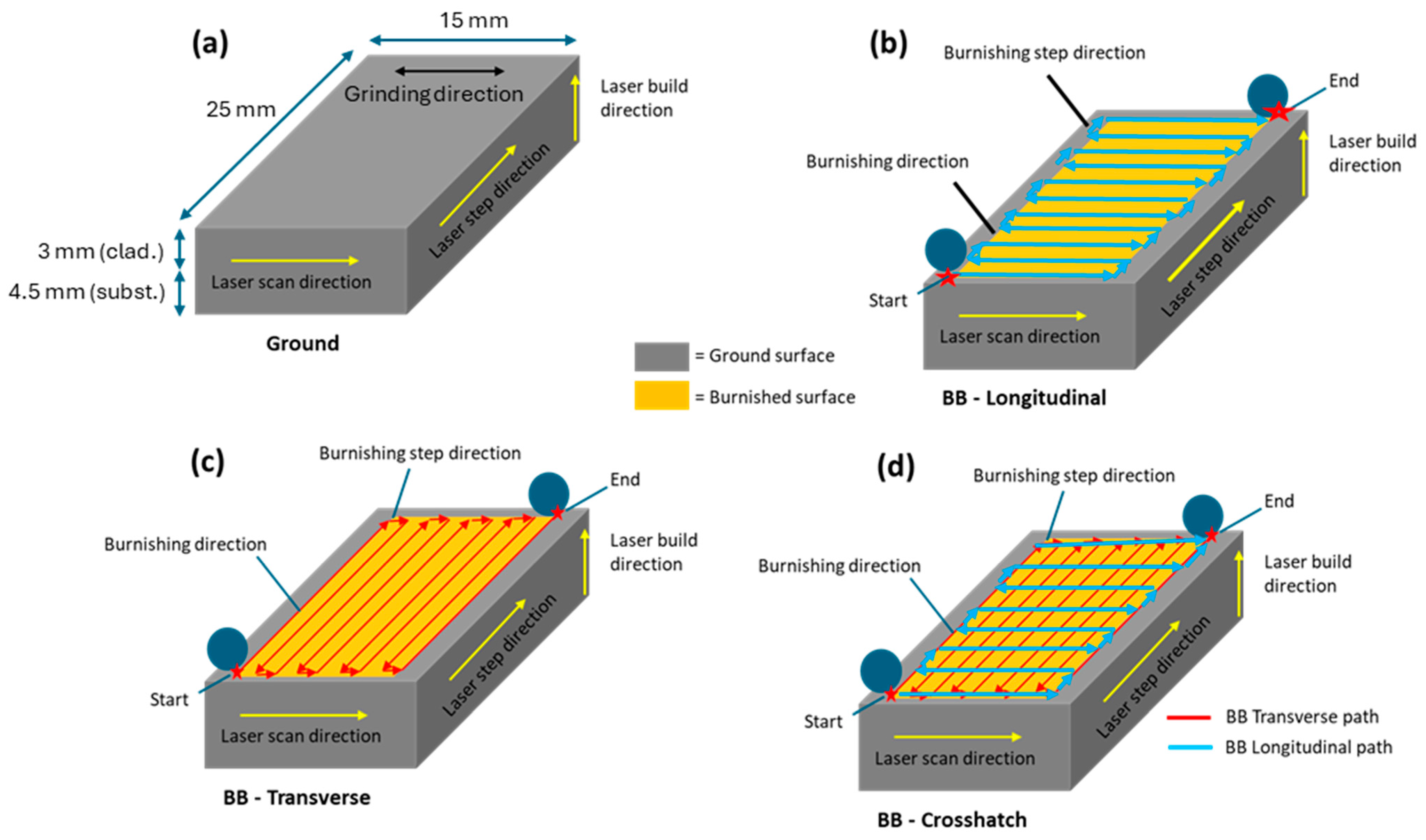
Each burnishing strategy was applied to two coupons, with the burnishing paths oriented relative to the laser scan direction. These included longitudinal, transverse, and crosshatch patterns, as illustrated in Figure 3 alongside the experimental setup. Longitudinal burnishing was performed parallel to the laser scanning direction, transverse burnishing was perpendicular to it, and crosshatch burnishing combined both directions to form a crisscross pattern.
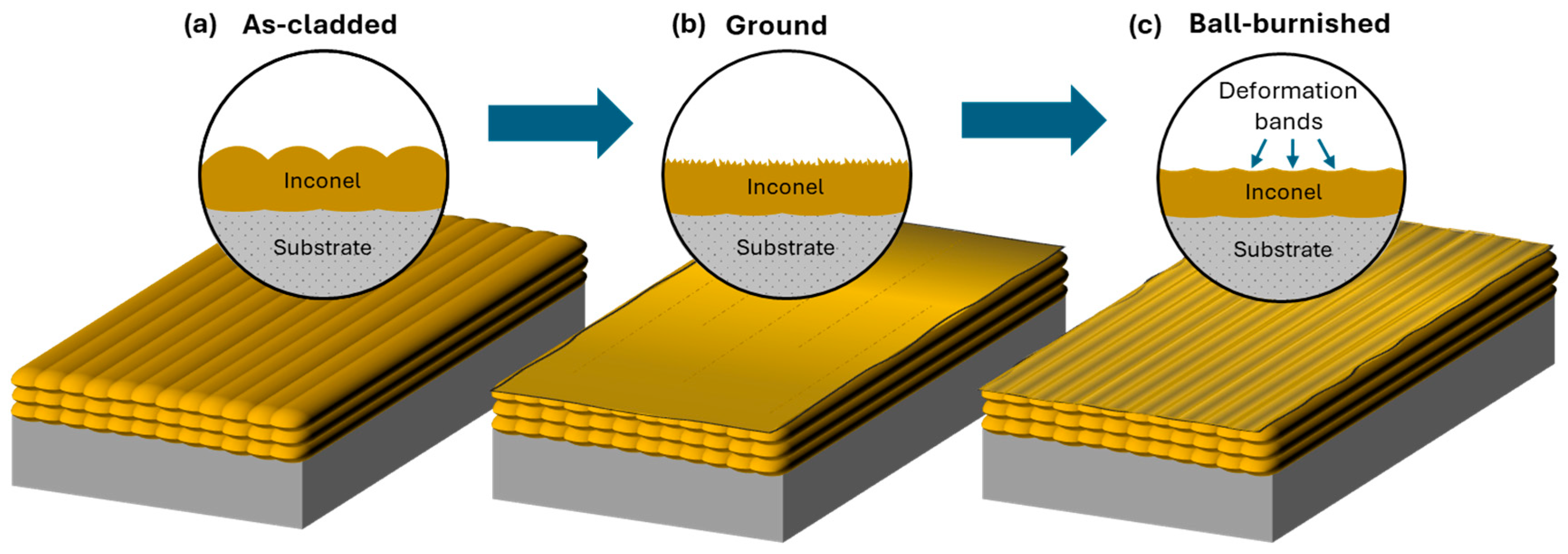
Following the burnishing process, the treated coupons were sectioned into smaller specimens for detailed surface characterization and performance evaluation. For clarity and consistency throughout the paper, the post-processed BB coupons are categorized into four groups: (i) Ground, (ii) BB-Longitudinal, (iii) BB-Transverse, and (iv) BB-Crosshatch. These notations will be used in subsequent sections for comparative analysis. The sequential and typical Inconel® 718 clad surface profile obtained before and after ball burnishing are illustrated in Figure 4, highlighting the morphological changes induced by the burnishing process.

2.3. Material Characterization

To evaluate the effects of the BB post-processing, a combination of surface, microstructural, and mechanical characterization techniques was employed. Surface roughness was measured using confocal laser microscopy (Olympus Lext OLS 500, Tokyo, Japan). A surface of each condition was scanned over a rectangular area of 12 × 4 mm, and the primary roughness parameters—average roughness (Ra), maximum height (Rz), average area roughness (Sa), and maximum area height (Sz)—were recorded. For each condition, three distinct zones were measured, and the average of these values was reported to ensure consistency and reliability.
Surface morphology was further examined using scanning electron microscopy (SEM, ZEISS Gemini microscope, Oberkochen, Germany), which provided detailed imaging of the ground and ball-burnished surfaces. To investigate microstructural changes induced by the BB process, electron backscatter diffraction (EBSD, Philips XL-30 FESEM, FEI Company, Hillsboro, OR, USA) analysis was conducted. Cross-sectional samples were prepared by sequential grinding with 1200-grit abrasive paper, followed by polishing with 9 μm and 6 μm diamond pastes. A final polishing step using oxide polishing suspension (OPS) was applied for 15 min to achieve a high-quality surface suitable for EBSD. The scans were performed over a 400 × 400 μm2 area with a step size of 0.5 μm, allowing for detailed analysis of grain structure and orientation.
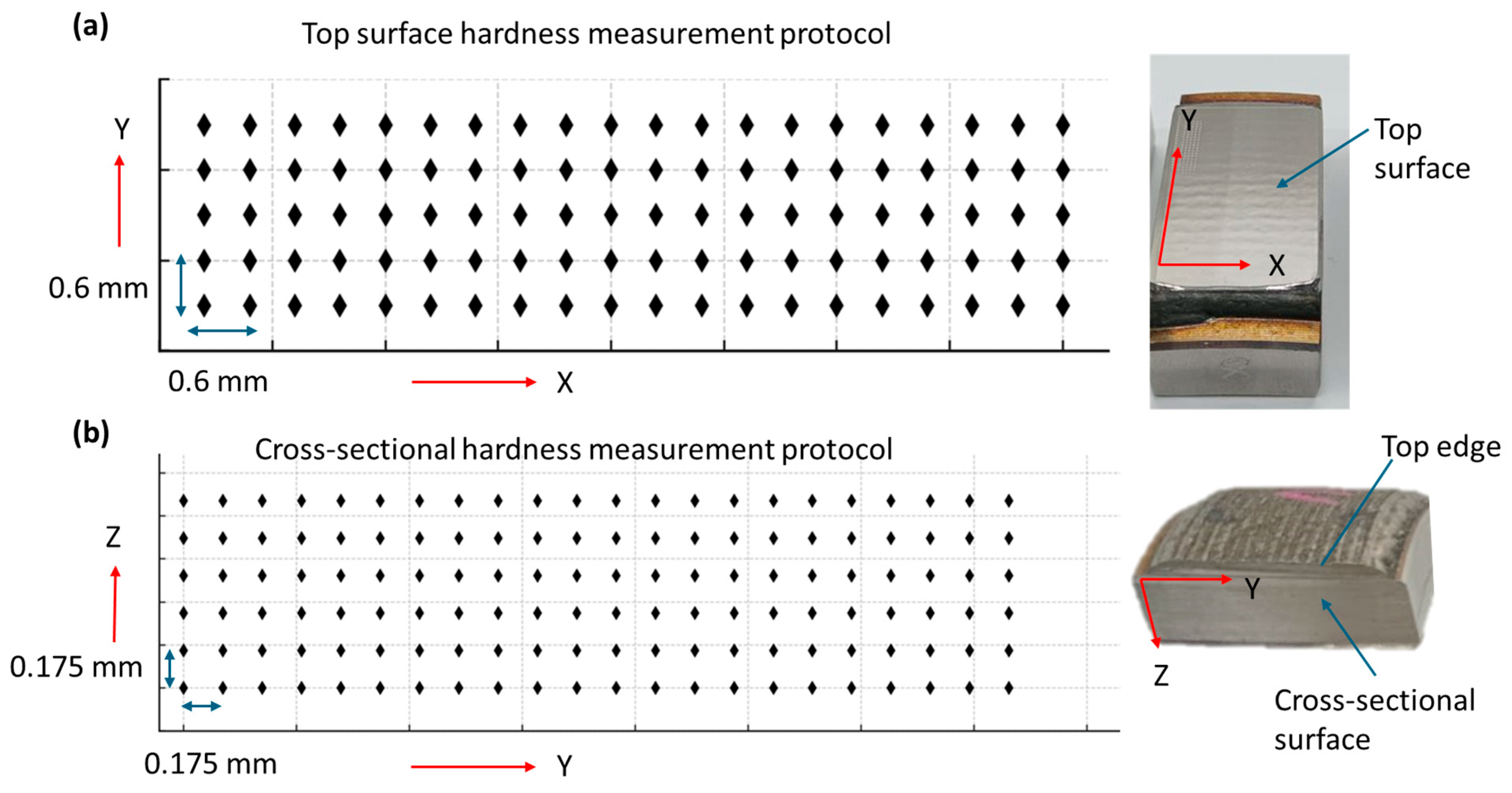
Microhardness testing was performed using a mechanical tester (Nanovea CB500, Irvine, CA, USA) to evaluate the hardness distribution on both the top surface and the cross-section of the samples. All tests followed the ASTM E384-17 standard [17], using a diamond pyramid indenter with a 10 s dwell time. For the top surface, a load of 5 kgf was applied, and a total of 100 indentations were made in a 20 × 5 array with 0.6 mm spacing between indents in both directions. For the cross-section, a reduced load of 0.1 kgf was used, and 132 indentations were performed in a 22 × 6 array with 0.175 mm spacing in both width and depth directions. The mapping protocol is illustrated in Figure 5. This setup enabled a detailed and consistent evaluation of hardness distribution and depth-wise variation resulting from the BB post-processing.

2.4. Performance Assessment

Low-velocity impact testing was conducted to evaluate the impact resistance and toughness of the treated surfaces. A 1.83 kg mass fitted with a 10 mm diameter hemispherical metal indenter was freely dropped from a height of 290 mm, delivering an impact energy of 5.2 J. The resulting permanent indentations on the surfaces were characterized using Laser Confocal Microscopy to quantify indentation volume and depth, providing a measure of the surface’s resistance to plastic deformation. Each surface condition was tested three times, and the average values were reported.
Sliding wear resistance was assessed using a rotary pin-on-disk apparatus (Micro Test MT series, Madrid, Spain) in accordance with the ASTM G99-23 standard [18]. Flat specimens were rotated in dry contact against a stationary 6 mm diameter alumina ball (grade 20). Prior to testing, both the ball and specimen surfaces were ultrasonically cleaned in ethanol and dried. The tests were performed under a normal load of 10 N, with a sliding speed of 0.1 m/s, a sliding track diameter of 10 mm, and a total sliding distance of 1000 m. Wear volume and surface morphology of the tribo-pairs were analyzed using Laser Confocal Microscopy (Olympus, Tokyo, Japan), while wear mechanisms were further examined via SEM. Weight loss due to wear was measured using a high-precision scale (OHAUS EX623, Parsippany, NJ, USA).
Corrosion performance was evaluated using potentiodynamic polarization testing in a three-electrode electrochemical cell (Pine Research Proteus Gamma I, Durham, NC, USA) containing 60 mL of a 3.5 wt.% NaCl aqueous solution (pH 6.5). The samples, with an exposed area of 1.6 cm2, served as the working electrode, while a saturated calomel electrode (SCE) was used as the reference, and a platinum sheet as the counter electrode. All electrodes were connected to a potentiostat (Pine Research WaveDriver series), and the cell was maintained at ambient temperature (25 °C).
Before each test, a 45 min stabilization period was applied to establish a steady open circuit potential (OCP). Linear polarization resistance (LPR) and linear sweep voltammetry (LSV) scans were then performed at a sweep rate of 0.2 mV/s. The polarization range was set to ±20 mV vs. OCP for LPR and from −200 to 1500 mV for LSV. This range was selected to capture the full electrochemical behavior of Inconel 718 in chloride environments, including the passive and breakdown (pitting) regions [19]. From the resulting Tafel plots, the corrosion potential (Ecorr), corrosion current density (icorr), and pitting potential (Epit) were determined for each condition.

3. Results and Discussions

3.1. Surface Roughness and Topography Analysis

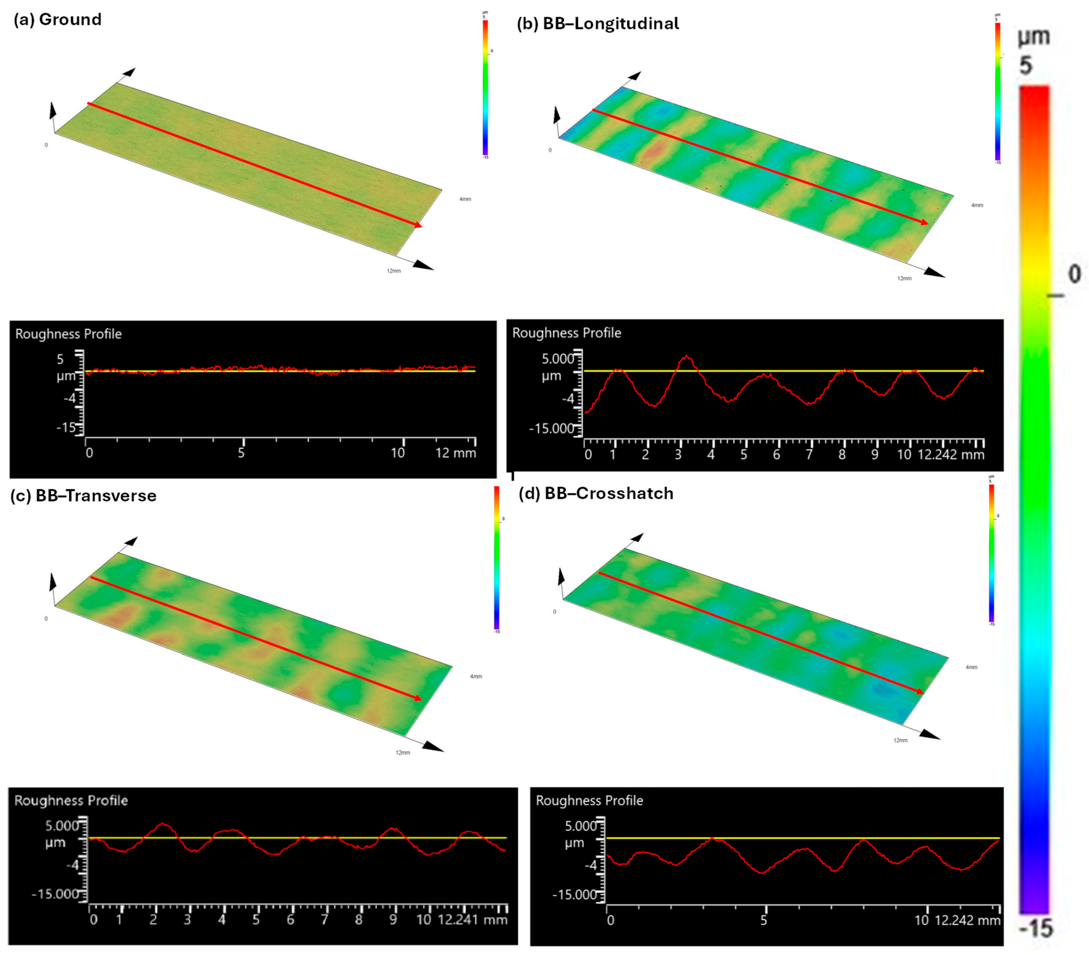
Figure 6 presents the surface topographies and corresponding roughness profiles for the Inconel 718 cladded surface in ground, BB-longitudinal, BB-transverse, and BB-crosshatch conditions. All BB-treated surfaces exhibit increased roughness compared to the ground surface, with distinct morphological differences depending on the path strategy. The BB-longitudinal condition displays a pronounced undulating texture, characterized by regularly spaced peaks and valleys aligned with the laser scan and burnishing direction. The roughness profile reveals periodic surface modulation with peak-to-valley amplitudes reaching up to 10 µm and a waviness pitch of approximately 2 mm. While the BB-transverse condition maintains a similar pitch, its amplitude is reduced to around 5 µm, indicating a smoother surface likely resulting from the burnishing path crossing the laser scan lines and distributing deformation more uniformly. The BB-crosshatch condition yields an intermediate texture, with less defined periodicity and a more isotropic profile, reflecting the multidirectional nature of the burnishing tool path. The structured deformation observed in the longitudinal case suggests a directional surface pattern that may influence functional performance, whereas the transverse and crosshatch strategies may offer improved uniformity and balance between roughness and anisotropy.
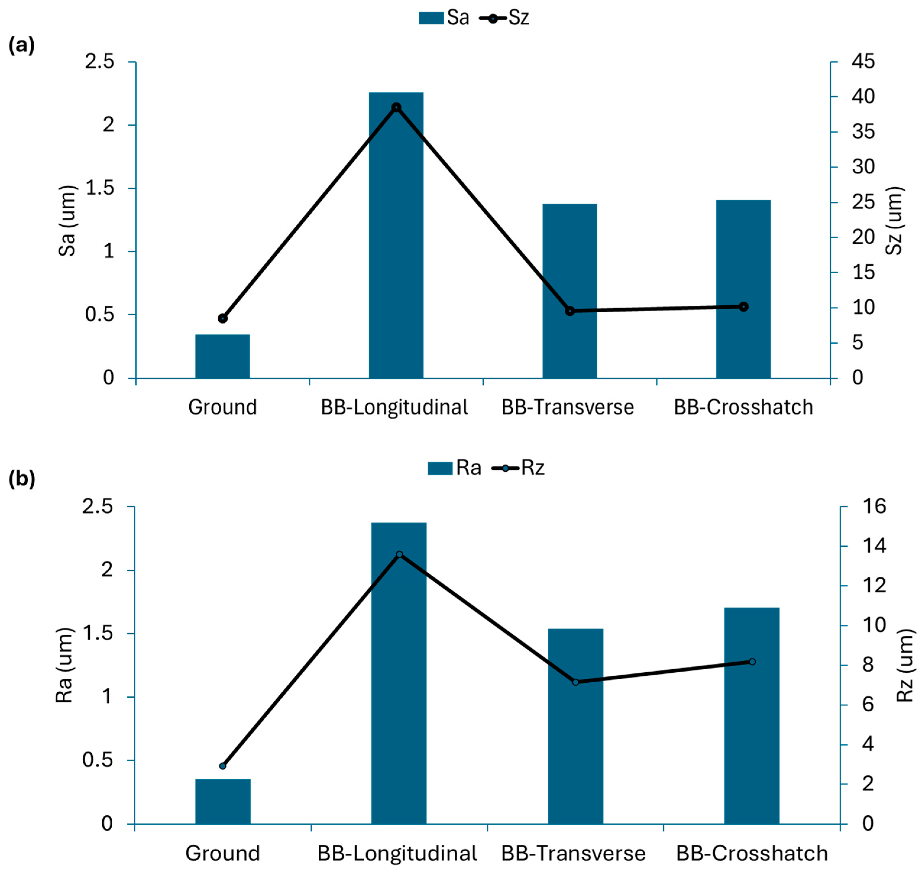
Figure 7 presents the roughness parameters Sa, Sz, Ra, and Rz for the different Inconel 718 cladded surface conditions. The ground condition exhibits the lowest roughness, with Ra and Sa values of 0.352 µm and 0.345 µm, and maximum height parameters Rz and Sz at 2.932 µm and 8.474 µm, respectively. In comparison, the BB-longitudinal condition shows the most significant increase across all metrics: Ra and Sa rise to 2.376 µm and 2.258 µm—more than 6.5 times higher than the ground values—while Rz and Sz increase to 13.614 µm and 38.658 µm, corresponding to 4.6 times increases, respectively. This confirms the pronounced surface modulation introduced by the longitudinal path strategy.
The BB-transverse condition results in a more moderate increase, with Ra and Sa values of 1.537 µm and 1.379 µm, roughly 4 times higher than the ground condition. Rz and Sz also increase to 7.163 µm and 9.554 µm, respectively, with Sz only slightly exceeding the ground value, suggesting a smoother surface with fewer extreme height variations. This agrees with the observed surface topographies. The BB-crosshatch condition yields Ra and Sa values of 1.705 µm and 1.407 µm—comparable to the transverse case—but with slightly higher Rz and Sz values of 8.183 µm and 10.152 µm. This indicates the presence of deeper isolated features, likely due to the multidirectional nature of the burnishing tool path.
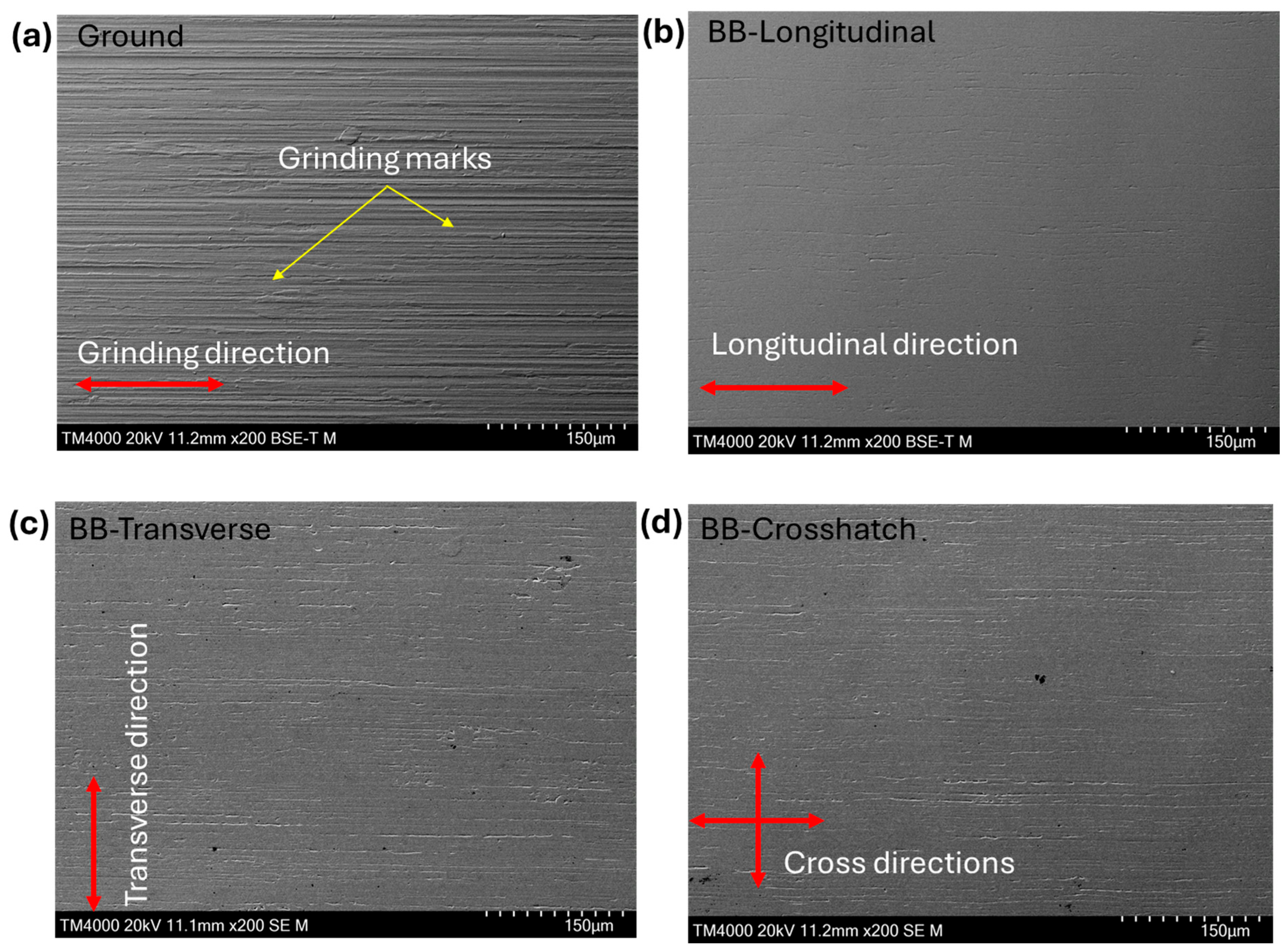
Figure 8 presents representative SEM micrographs of the Inconel 718 cladded surfaces. The ground surface clearly displays parallel grinding marks, characteristic of the finishing process and indicative of controlled surface abrasion. In contrast, the BB-longitudinal surface appears significantly smoother, with no visible grinding marks and evidence of extensive plastic deformation along the burnishing direction. The BB-transverse and BB-crosshatch surfaces retain some visible grinding traces, suggesting that deformation was less uniform or incomplete in these configurations. The presence of residual marks in the transverse and crosshatch conditions aligns with the roughness data and topographical observations, indicating that the longitudinal strategy was most effective in modifying the surface morphology.
A comparison between the confocal topography (Figure 6b) and SEM micrograph (Figure 8b) of the BB-Longitudinal surface reveals an apparent discrepancy. While the SEM image suggests a smoother surface free of grinding marks, the confocal scan shows pronounced undulations aligned with the burnishing and cladding directions. This contrast arises from the nature of ball burnishing, which compacts grinding-induced grooves while simultaneously introducing broader surface waves due to plastic deformation. These undulations are influenced not only by the burnishing toolpath but also by microstructural heterogeneities in the laser-cladded layer—particularly the softened overlap zones formed by ~50% track overlap. These zones deform more readily under burnishing, leading to wave-like surface modulation.
The combined analysis of surface topography, roughness parameters, and SEM imaging confirms that BB post-processing significantly alters the surface morphology of laser-cladded Inconel 718, with the degree of deformation strongly influenced by the burnishing path strategy. Compared to the uniform morphology of the ground surface, BB produces a distinctly heterogeneous texture with elevated roughness and pronounced peak-to-valley features. The BB-longitudinal strategy induces the most intensive deformation, as reflected in the highest roughness values, while transverse and crosshatch paths result in more moderate and directionally distributed changes. These differences are closely linked to the microstructural heterogeneity introduced during laser cladding, particularly due to the overlapping of tracks. Reheated zones formed by overlap correspond closely to the ~2 mm spacing (50% overlapping in 4.8 mm beam spot diameter) observed between surface peaks, suggesting a direct link between the cladding strategy and the surface modulation seen after BB. These regions undergo repeated thermal cycles, altering local microstructure and properties, which in turn affects their mechanical response to BB. Harder zones, typically associated with finer microstructures from rapid cooling, resist plastic deformation and remain at the original surface level, whereas softer, reheated zones deform more readily, contributing to deeper valleys. Although SEM images suggest smoother surfaces post-BB, roughness measurements reveal that the process amplifies underlying material heterogeneity. This uneven deformation behavior reinforces the observed variability in surface roughness and highlights the influence of thermal history and overlap geometry on post-processing outcomes.

3.2. EBSD Microstructural Analysis

3.2.1. Kernel Average Misorientation (KAM) Analysis

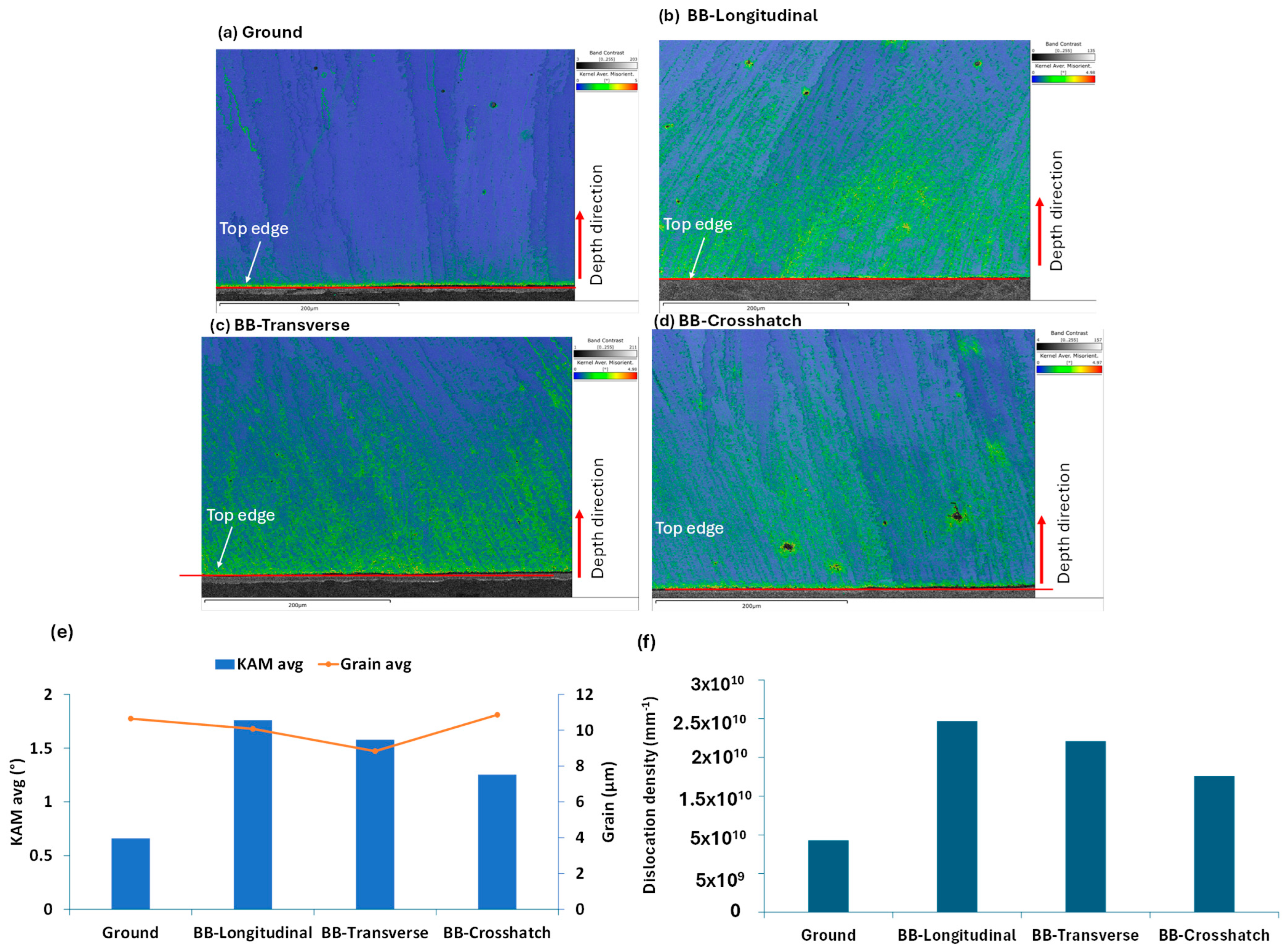
Figure 9 presents Kernel Average Misorientation (KAM) maps derived from EBSD data, illustrating localized increases in misorientation—particularly near grain boundaries—for all BB-treated surface conditions compared to the ground baseline.
The BB-treated specimens exhibit a visibly thicker strain-hardened layer, extending deeper into the material. Among the BB surface conditions, the longitudinal and transverse directions showed the highest KAM values, approximately 1.8° and 1.6°, respectively. The crosshatch condition exhibited a more moderate increase at around 1.3°, while the ground condition remained at approximately 0.6°.
Corresponding dislocation density estimates were 9.28 × 109 mm−2 (Ground), 2.47 × 1010 mm−2 (BB-Longitudinal), 2.21 × 1010 mm−2 (BB-Transverse), and 1.76 × 1010 mm−2 (BB-Crosshatch). These values indicate a substantial rise in geometrically necessary dislocations (GNDs), which are directly associated with lattice curvature and can be inferred from EBSD orientation gradients [20].
The elevated KAM values and dislocation densities confirm that the BB process induces significant local plastic deformation, consistent with prior studies on nickel-based alloys [21]. The accumulation of GNDs contributes to surface strengthening, while the modified grain orientation and boundary distribution reflect microstructural refinement. This behavior aligns with the principles of strain hardening and dislocation theory, where dislocations of similar sign contribute to measurable lattice curvature and enhanced mechanical properties. The deformation pattern observed in the KAM maps (Figure 9) aligns closely with the surface topography shown in Figure 6. Specifically, the BB-Longitudinal sample, which exhibited the highest misorientation and dislocation density, also showed the most pronounced surface undulations in the confocal scan. These periodic waves reflect concentrated plastic deformation along the burnishing path, particularly in the softened overlap zones of the laser-cladded layer. This correlation reinforces the interpretation that longitudinal burnishing promotes deeper strain accumulation and residual stress generation, which may contribute to the enhanced corrosion potential observed in BB-Longitudinal samples.
Recent in situ EBSD investigations on nickel-based single-crystal superalloys have further revealed the formation and propagation of deformation bands during plastic deformation. These bands initially facilitate softening but subsequently activate secondary slip systems that promote hardening [22]. The elevated misorientation regions observed in BB-treated samples may reflect similar banding phenomena, particularly in the longitudinal and transverse directions where strain is more directionally imposed.
Moreover, the variation in KAM and dislocation density across BB orientations may be attributed to crystallographic anisotropy. Nickel-based alloys exhibit pronounced orientation sensitivity due to their face-centered cubic (FCC) structure and phase composition, which influence how different grain orientations respond to mechanical surface treatments [22].

3.2.2. Grain Boundary and Texture Analysis

The EBSD inverse pole figure (IPF) maps presented in Figure 10 reveal a pronounced columnar grain structure aligned along the build direction, consistent across all surface conditions. This texture is predominantly oriented between the ⟨001⟩ and ⟨101⟩ crystallographic directions, indicative of a strong preferred orientation commonly observed in laser-based additive manufacturing of Inconel 718, where directional solidification promotes epitaxial grain growth along the thermal gradient. The grain boundary character distribution varies significantly between the ground and BB-treated surfaces, reflecting the influence of mechanical surface treatments on microstructural evolution.
A comparative analysis of grain boundary character reveals notable differences between the ground and BB-treated surfaces. In the ground condition, the grain boundary population is relatively balanced, with low-angle grain boundaries (LAGBs, 2–15°) comprising 43.4% and high-angle grain boundaries (HAGBs, >15°) accounting for 56.6%. This distribution suggests a moderate level of stored strain and a microstructure that has undergone partial recrystallization. In contrast, the BB-treated conditions—particularly the longitudinal and transverse directions—exhibit a marked increase in LAGB fractions (75.9% and 72.0%, respectively), accompanied by a corresponding reduction in HAGBs. This shift implies that the unidirectional BB processes introduce significant plastic deformation, promoting the formation of subgrain structures and increasing dislocation density, as supported by the KAM analysis. The attenuation of IPF color contrast near the top edges of the BB-treated samples further corroborates this, indicating regions of elevated local misorientation and strain accumulation.
The BB-crosshatch condition presents an intermediate state, with LAGBs at 54.6% and HAGBs at 45.4%, suggesting a more isotropic mechanical interaction compared to the directional BB treatments. This variation in grain boundary character aligns with literature on severe plastic deformation, where materials typically evolve from a high fraction of LAGBs during early deformation stages toward a steady-state microstructure characterized by a balance between LAGBs and HAGBs [23]. The observed increase in LAGBs in BB-treated surfaces may be attributed to continuous dynamic recrystallization, a mechanism known to operate under conditions of high strain and temperature, facilitating the rearrangement of dislocations into low-angle boundaries without the nucleation of new grains [23].
These microstructural changes have important implications for mechanical performance. The prevalence of LAGBs is often associated with enhanced strength due to dislocation pile-up, but may also influence fatigue behavior and crack propagation pathways. Conversely, the reduction in HAGBs, which typically act as effective barriers to dislocation motion, could reduce resistance to grain boundary sliding and localized deformation, potentially affecting creep and fatigue resistance [24,25]. Further investigation into the correlation between grain boundary character and mechanical properties is warranted to optimize surface treatment strategies for performance-critical applications.

3.3. Hardness Analysis

3.3.1. Surface Hardness Analysis

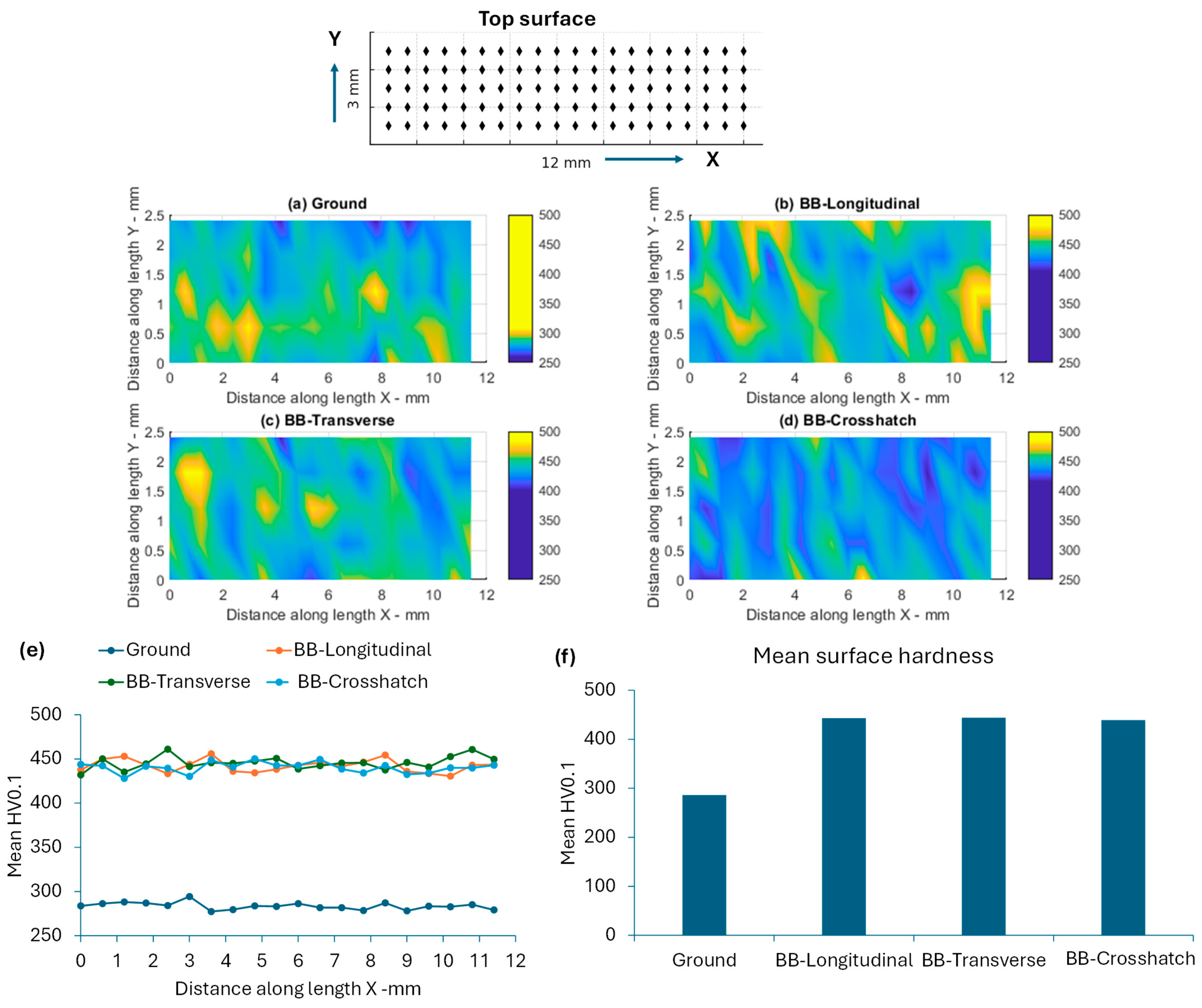
Figure 11 illustrates the spatial distribution of surface hardness across the treated samples. The results demonstrate that all BB patterns—Longitudinal, Transverse, and Crosshatch—produced a substantial increase in surface hardness compared to the ground condition. BB-treated surfaces exhibited average hardness values ranging from 428 to 461 HV5, whereas the ground surface showed values between 260 and 294 HV5. This led to an increase in hardness by the BB treatments by up to 56–64%, as compared to the ground surface.
Among the BB-treated samples, a relatively low variation in hardness was observed indicates a consistent hardening effect across all patterns. This uniformity suggests that the directionality of the BB process does not significantly influence the degree of surface hardening. Similar observations have been reported in studies on nickel-based superalloys, where BB has been shown to enhance surface integrity regardless of the applied orientation [11].
The observed hardness improvement is primarily attributed to the plastic deformation induced by the burnishing process, which promotes work hardening and leads to the formation of a denser, more resilient surface layer. Additionally, BB is known to introduce compressive residual stresses, which contribute to enhanced fatigue resistance and surface durability [26].
Although no statistically significant differences were observed between the BB patterns, the overall surface enhancement relative to the ground condition underscores the effectiveness and robustness of the BB technique. The absence of pattern-dependent variation implies that practical considerations—such as component geometry, accessibility, or process efficiency—can guide the selection of BB strategy without compromising mechanical performance. This finding is consistent with broader literature highlighting the versatility and reliability of BB in improving the surface integrity properties of Inconel 718 and similar alloys [11,27].

3.3.2. Cross-Section Hardness Analysis

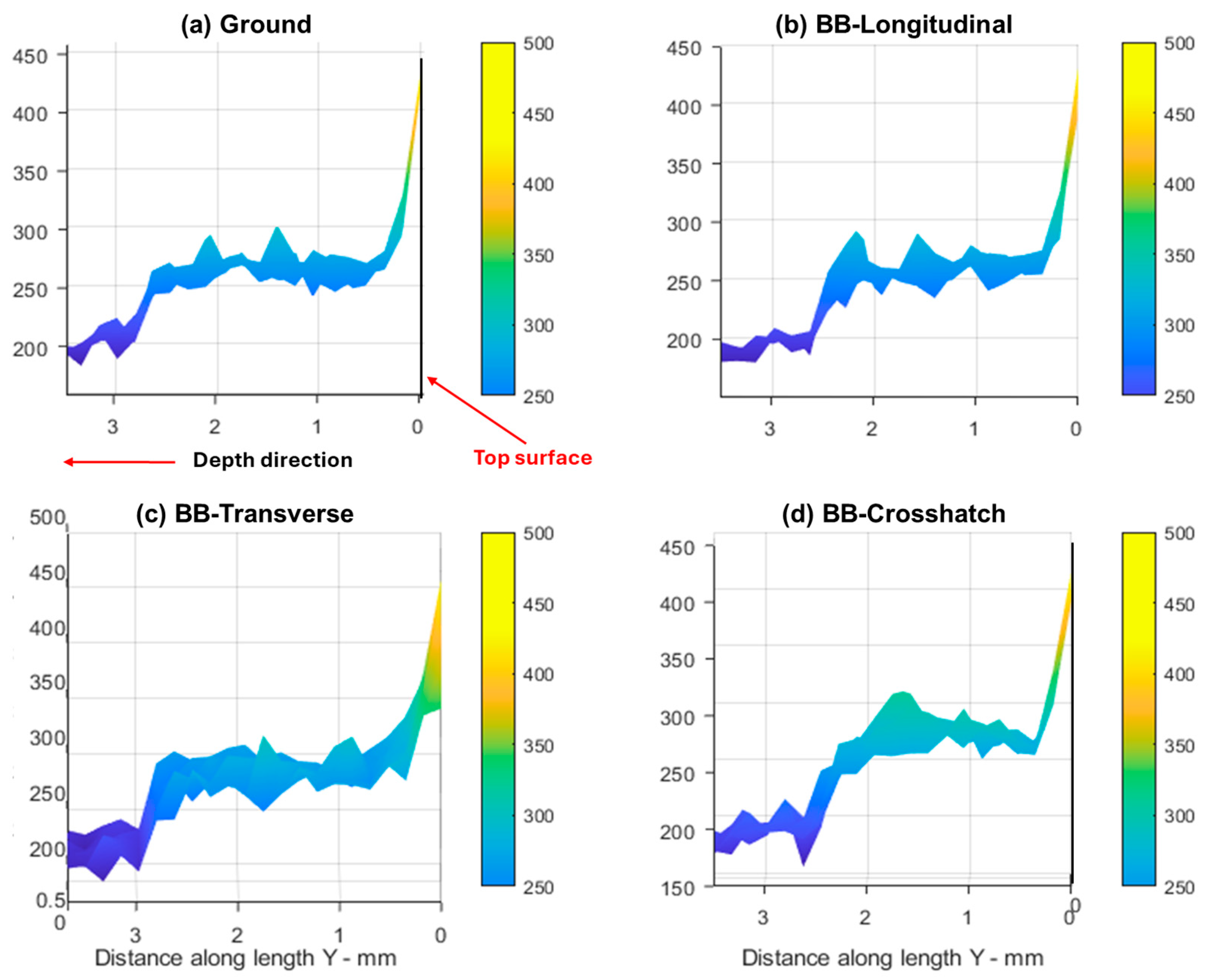
Figure 12 presents the cross-sectional hardness profiles for all surface conditions using a low-load indentation (HV0.1). The results show no significant variation in surface hardness between the ground and BB-treated samples near the surface under this load. However, this observation contrasts with the HV5 surface hardness results, where BB-treated samples consistently exhibited higher hardness values than the ground condition. This discrepancy highlights the influence of indentation depth on the measured response and suggests differences in the depth and intensity of the work-hardened layers produced by each treatment.
The HV0.1 test, with its shallow penetration, is sensitive to surface-level changes and effectively captures the thin hardened layer produced by grinding. In contrast, the HV5 test averages hardness over a larger volume, including subsurface regions. The higher HV5 values observed in BB-treated samples indicate that BB induces a deeper and more uniform hardened zone. This is consistent with prior studies showing that grinding typically produces a hardened layer between 10 and 50 µm, while BB can extend this zone several times deeper due to more intense plastic deformation and the introduction of compressive residual stresses [27,28]. Similar findings have been reported for stainless steels such as AISI 431, where ball burnishing produced hardened layers extending up to 250 µm, underscoring the depth and intensity of plastic deformation achievable through this process [9]. While material-specific responses may vary, these results reinforce the broader understanding that BB induces significantly deeper hardening compared to conventional surface treatments like grinding.
The deeper hardening effect of BB has been linked to its ability to modify subsurface microstructure and hence, leading to enhanced mechanical properties such as fatigue resistance and wear durability. In contrast, grinding primarily affects the immediate surface, with limited subsurface impact. This explains why BB-treated samples maintain higher hardness under larger indentation loads, while ground samples show a sharper drop due to the thinness of the hardened layer.

3.4. Materials Performance

3.4.1. Impact Resistance

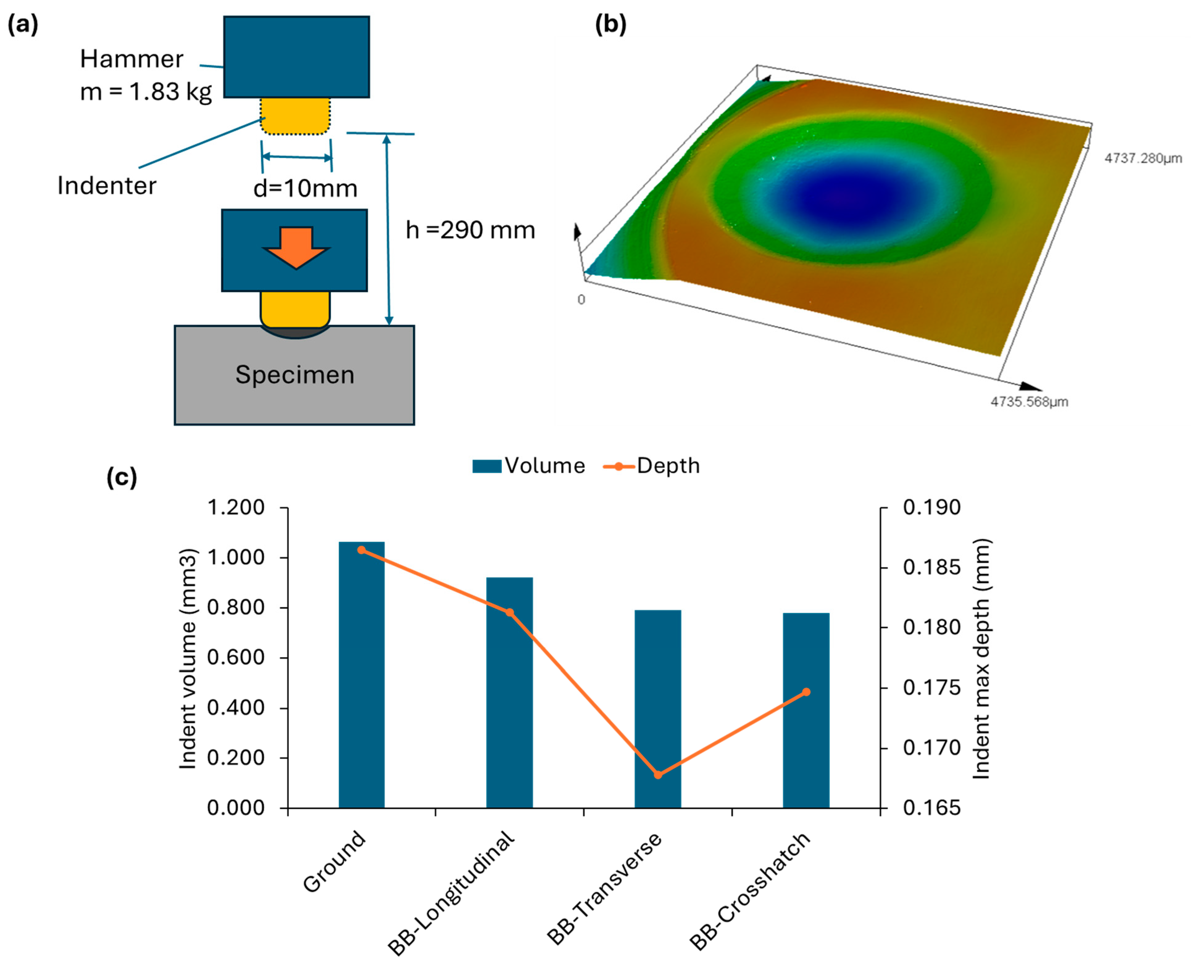
All BB-treated surfaces demonstrated improved resistance to plastic deformation compared to the ground condition in the impact testing, as evidenced by reduced indentation volumes and depths presented in Figure 13. The BB-transverse and BB-crosshatch patterns showed very similar performance, with indentation volumes of 0.792 mm3 and 0.780 mm3, and depths of 0.168 mm and 0.175 mm, respectively. The BB-longitudinal condition, while slightly less effective than the other BB patterns, still showed a significant improvement over the ground surface, with an indentation volume of 0.923 mm3 and depth of 0.181 mm.
The results demonstrate that BB treatments enhance surface toughness by introducing residual compressive stresses that improve the surface’s ability to absorb and distribute impact energy. The transverse and crosshatch patterns, in particular, benefit from multi-directional plastic deformation, which promotes a more uniform and isotropic stress distribution—contrasting with the directional nature of the laser cladding path. This effect has been supported by previous studies, which found that multi-directional ball burnishing leads to deeper and more evenly distributed compressive stresses, thereby improving surface integrity and impact behavior [29].

3.4.2. Sliding Wear Testing

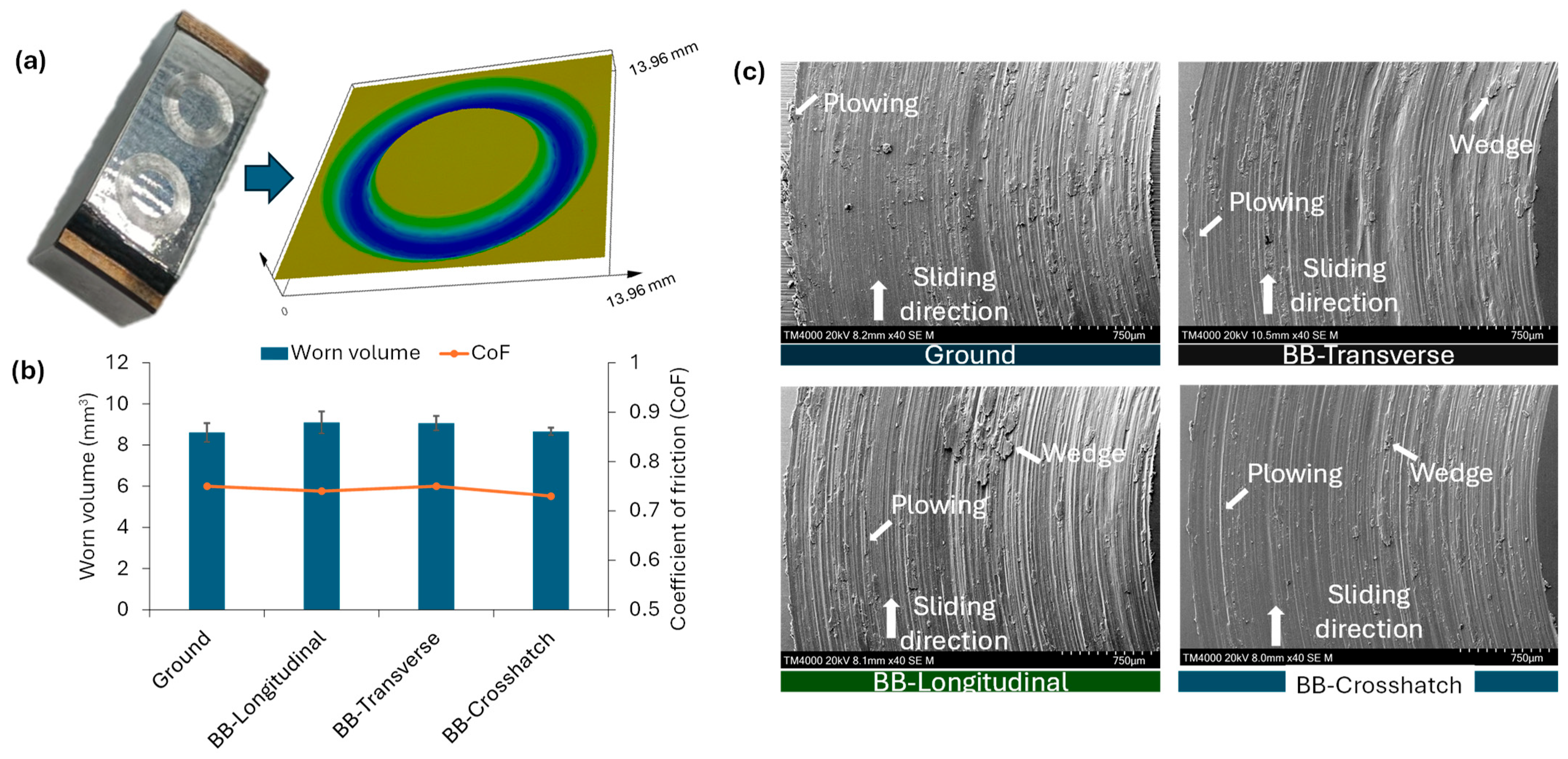
To assess the tribological performance of the processed surfaces, pin-on-disc tests were performed under dry sliding conditions. The results showed that the average volume loss ranged from 8.6 to 9.1 mm3, and the coefficient of friction (CoF) stabilized between 0.73 and 0.75 (Figure 14b), indicating no statistically significant difference between ground and ball-burnished (BB) surfaces. SEM analysis (Figure 14c) revealed abrasion as the dominant wear mechanism for all samples, characterized by ploughing marks aligned with the sliding direction. BB-treated surfaces exhibited additional wedging features, indicative of localized plastic deformation likely associated with compressive residual stresses introduced during BB. The presence of more pronounced wedging suggests a delayed onset of severe wear compared to the ground condition. However, once the hardened layer was penetrated, the surface morphology and wear progression are likely to be converged to that of the ground condition.
Differences emerged when analyzing the evolution of the CoF during sliding. As shown in Figure 15, BB-treated samples exhibited initially lower fluctuation amplitudes for BB-treated samples, indicating a more stable run-in compared to the ground condition. However, the CoF response gradually converged to that of the ground samples once the BB-hardened layer was worn through—at approximately 100 m for BB-longitudinal and beyond 200 m for BB-transverse and BB-crosshatch conditions—indicating only transient benefits from BB-induced near surface strengthening.
Although BB increases near surface hardness in Inconel 718, the pin on disc configuration employed here promotes a wear depth that rapidly exceeds the BB affected layer thickness. Once this occurs, the contact response is governed by the bulk material properties, diminishing the influence of surface integrity enhancements. This interpretation is consistent with established observations that BB can elevate surface integrity and compressive residual stresses, yet offers limited wear resistance gains when the effective wear depth surpasses the hardened zone [11,27,30]. The orientation effect (longitudinal versus transverse/crosshatch) suggests that toolpath induced texture and residual stress anisotropy prolongs the run in for transverse and crosshatch conditions but does not alter the long sliding steady state under the present load and distance.
For high load or long-distance sliding, BB alone is unlikely to deliver durable wear improvements, because the protective layer is too shallow relative to the material removal rate. In such regimes, BB is best viewed as a run-in enhancer (i.e., smoother initial contact, reduced fluctuation amplitude) rather than a steady state wear reducer. More durable benefits likely require complementary treatments that (i) produce a deeper hardened zone (e.g., severe shot peening, laser shock peening) or (ii) introduce a hard, wear resistant surface (e.g., coatings or diffusion treatments) to prevent rapid exposure of the bulk substrate—an approach suggested in prior reports for Inconel 718 under abrasive sliding [11,27,30].

3.4.3. Electrochemical Corrosion Test

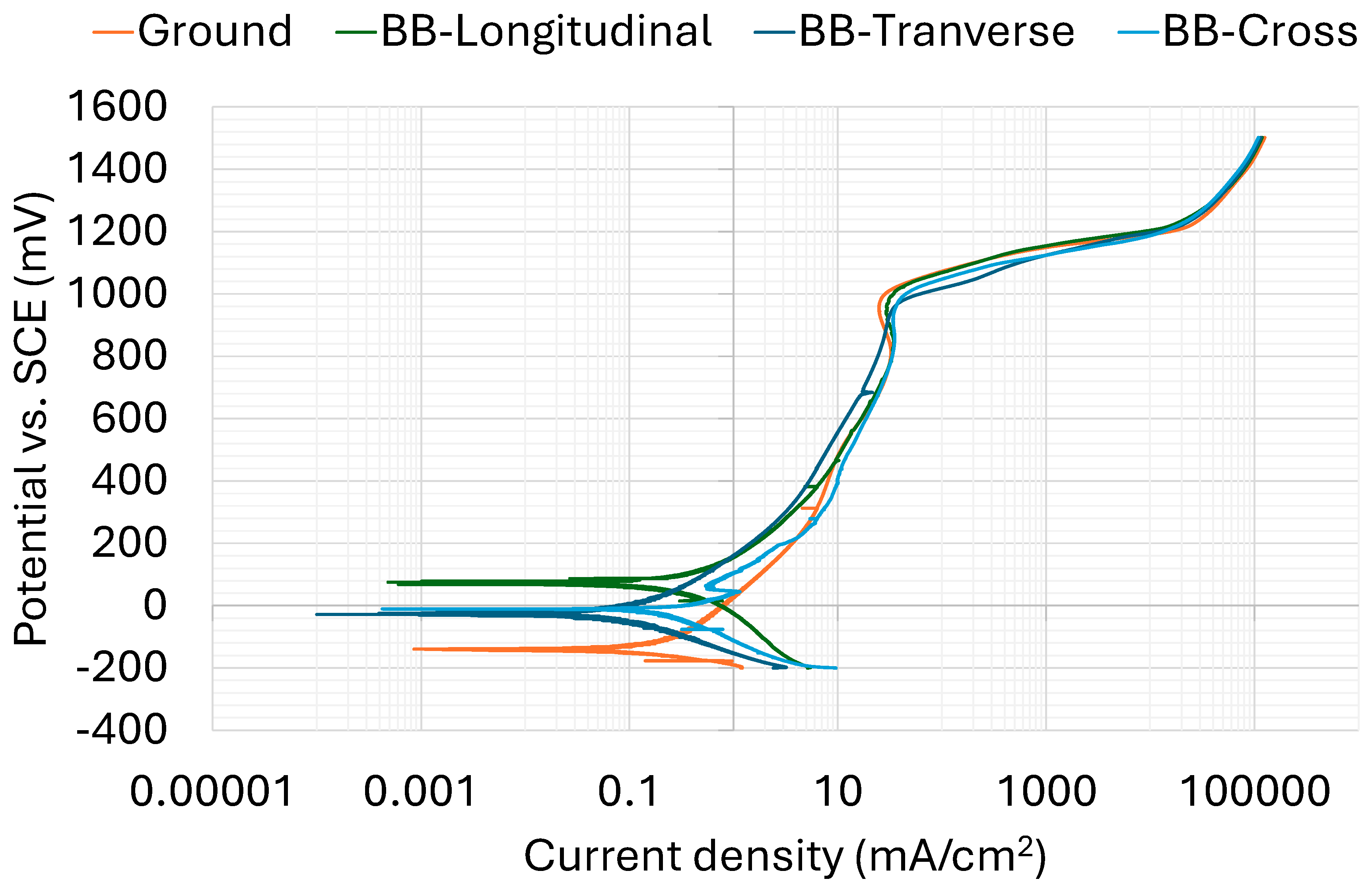
Figure 16 presents the Tafel polarization curves comparing corrosion potential (Ecorr) and corrosion current density (Icorr) for the ground and BB-treated specimens. Relative to the ground sample, all BB-treated surfaces exhibited a shift in the polarization curve toward more noble potentials (upward) and lower current densities (leftward), which generally indicates improved corrosion resistance. In electrochemical terms, a higher Ecorr generally reflects a reduced thermodynamic tendency for corrosion, while a lower Icorr corresponds to a slower corrosion rate.
Table 2 summarizes the corrosion results extracted from the Tafel plots presented in Figure 16. BB-Longitudinal sample demonstrated the highest positive corrosion potential of Ecorr = 13 mV vs. SCE, indicating a marked improvement in corrosion resistance among all treatment strategies, while the ground sample showed a highly negative Ecorr = −109 mV vs. SCE. This positive shift in Ecorr for BB-Longitudinal suggests a decreased thermodynamic tendency for corrosion, which is aligned with the findings in the previous literature where more positive corrosion potentials correlate with enhanced corrosion resistance [31]. BB-Transverse and BB-Crosshatch samples exhibited intermediate Ecorr values of −73 mV and −43 mV, respectively, indicating a moderate tendency toward corrosion.
In terms of corrosion current density (icorr), which is indicative of the rate of corrosion, BB-Longitudinal sample exhibited a slightly high icorr (of 0.021 mA/cm2) compared to the other samples. This higher icorr suggests an increased rate of general corrosion, despite the improved Ecorr. In contrast, the ground sample showed a lower icorr (0.017 mA/cm2), indicating a slower corrosion rate. The BB-Transverse sample exhibited the lowest icorr (0.015 mA/cm2), reflecting the slowest corrosion rate of all samples, whereas the BB-Crosshatch sample displayed a moderate corrosion rate with an icorr of 0.02 mA/cm2. These differences in icorr could be linked to microstructural variations induced by different surface treatment strategies, where factors such as surface roughness, texture and micro segregation could lead to localized variations in corrosion behavior, as previously reported in similar studies [32].
For instance, the pronounced undulations exhibited on the BB-Longitudinal surface (Figure 6b) may theoretically increase the effective surface area exposed to the electrolyte. Since the corrosion cell assumes a flat circular area for Icorr calculations, this could lead to a comparable slight overestimation of corrosion current density, as demonstrated by a marginal increase in Icorr average for this condition. The more significant finding was the higher Ecorr, which may be attributed to the greater plastic deformation and compressive residual stresses induced by the alignment of the burnishing path with the cladding direction. Supporting data from KAM analysis and hardness mapping suggest enhanced surface strain, although the relatively high standard deviation in Ecorr indicates non-uniform deformation—likely due to alternating hard and soft zones created by the cladding overlap. This highlights the complex interplay between surface morphology and corrosion behavior and warrants further investigation.
Pitting potential (Epit) is another critical parameter for evaluating resistance to localized corrosion, particularly in aggressive chloride environments. BB-Longitudinal sample exhibited the highest pitting potential of 1165.5 mV vs. SCE, suggesting the formation of a stable passive film that effectively resists breakdown in the chloride solution. In comparison, BB-Transverse and BB-Crosshatch samples exhibited slightly lower Epit values of 1158 mV and 1145 mV, respectively, indicating a marginally higher susceptibility to pitting. Figure 17 shows the optical microscopic photos of the corroded surfaces treated by grinding and burnishing. For all surface conditions, a passivation layer is formed on the surface, which promotes the pitting corrosion resistance. This passive layer is reported to be made of CrO3, as its formation is very typical for Inconel 718 alloys when immersed in chloride solution. Traces of pitting were observed on all the surfaces, indicating the onset of breakdown of passivation layer. As can be seen from Figure 17b, along all conditions, BB-Longitudinal surface exhibited the lowest number of pitting with larger area of intact passive layer, as compared to BB-Transverse and BB-Crosshatch, confirming again its higher pitting resistance. This finding is consistent with prior research indicating that materials with lower Epit values tend to experience passive film breakdown more readily in chloride-containing environments [33]. Moreover, the results are aligned with observations in stainless steel corrosion studies, where variations in microstructure and surface morphology are known to significantly affect both general and localized corrosion performance [34].
In addition to Tafel parameters, polarization resistance (Rp) values were retrieved and included in Table 2 to provide further insight into general corrosion behavior. BB-Transverse exhibited the highest Rp (1.23 ± 0.01 MΩ.cm2), indicating the lowest corrosion rate, followed by the ground condition (1.05 ± 0.2 MΩ.cm2). In contrast, BB-Longitudinal and BB-Crosshatch showed lower Rp values (0.63 ± 0.2 MΩ.cm2 and 0.53 ± 0.2 MΩ.cm2, respectively), suggesting increased corrosion activity. These trends align with the icorr data and reinforce the interpretation that BB-Transverse offers the most balanced corrosion performance. The reduced Rp in BB-Longitudinal and BB-Crosshatch may be attributed to increased surface roughness and microstructural heterogeneity introduced by directional burnishing and cladding overlap zones.
It is also worth noting that the stabilized OCP values (after 45 min of exposure) provide insight into the initial electrochemical stability of each surface condition. The BB-Longitudinal sample exhibited the most positive OCP (+14 mV vs. SCE), suggesting a relatively stable passive surface prior to external perturbation. In contrast, the ground and BB-Transverse samples showed more negative OCP values (−61 mV and −77 mV vs. SCE, respectively), indicating a higher initial tendency toward corrosion. These OCP trends are generally consistent with the Ecorr values obtained from Tafel analysis, although slight deviations may arise due to surface changes during the polarization sweep.

4. Conclusions

This study is the first to systematically compare ball burnishing path strategies relative to the laser cladding direction, revealing the critical role of directional deformation in optimizing the corrosion and impact resistance of laser-cladded Inconel 718 alloys. The following are the major findings of the study.
  • Compared to the ground surface, the burnishing produced modulated surface profile, and this is more pronounced for BB-Longitudinal condition, while BB-Transverse and BB-Crosshatch exhibited moderate increase in profile and surface roughness. BB-Crosshatch may be selected if improved roughness is preferred.
  • EBSD results showed that the burnishing induced the plastic straining in the cladded surface, as compared to the ground specimen. BB-Longitudinal and BB-Transverse showed higher KAM and dislocation density from the top edge. This is also aligned with the increase in LAGBs and reduction in HAGBs for both conditions. BB-Crosshatch seems to reduce these effects by neutralizing the straining due to second pass of burnishing direction perpendicular to first pass.
  • The burnishing increased surface hardness by up to 64%, as compared to the ground surface, while the effect of BB path strategy on hardness is relatively small or marginal. However, BB-Transverse showed higher cross-sectional hardness with deeper modification layer up to about 400 µm, as opposed to BB-Longitudinal and BB-Crosshatch with improved hardness depth of about 250 µm. This is aligned with EBSD results.
  • BB-Longitudinal and BB-Crosshatch conditions exhibited 35% reduction in indent volume and 11% reduction in indent depth compared to the ground sample. This enhancement was attributed to improved surface hardness introduced by ball burnishing, which enhanced the material’s yielding resistance to impact loading.
  • BB-Longitudinal and BB-Transverse showed higher worn volume which can be due to high surface roughness, while BB-Crosshatch showed moderate resistance to wear. CoF followed the trend for worn volume for BB-treatment patterns. SEM analysis confirmed abrasion as the dominant wear mechanism for all cases.
  • Compared to other treatments, BB-Longitudinal pattern enhanced corrosion resistance significantly, as evidenced by a higher corrosion potential (Ecorr). A slight increase in corrosion current density (icorr) indicated a marginally faster general corrosion rate. For all treated conditions, the pitting potential (Epit) remained consistent, demonstrating maintained resistance to localized corrosion. The discrepancy between SEM and confocal topography highlights the complex interplay between surface smoothing and induced undulations. These features may influence corrosion potential through changes in surface strain and residual stress distribution, particularly when burnishing is aligned with the cladding direction.

Author Contributions

G.F.: writing—review & editing, conceptualization, methodology, validation, formal analysis, investigation, writing—original draft. A.H.: writing—review & editing, conceptualization, methodology, validation, formal analysis, investigation, writing—original draft. A.R.: validation, investigation, data curation, writing—review & editing. M.U.: supervision, validation, investigation, data curation, writing—review & editing. C.H.: Supervision, writing—review & editing. T.S.: Supervision, writing—review & editing. All authors have read and agreed to the published version of the manuscript.

Funding

This research received no external funding.

Data Availability Statement

The original contributions presented in this study are included in the article. Further inquiries can be directed to the corresponding author.

Acknowledgments

The authors would like to acknowledge the use of the optical microscope, scanning electron microscope, and micro-indenter provided by Microscopy Australia, a facility that is co-funded by the University of South Australia, the State Government of South Australia and the Australian Federal Government, and the use of laser confocal microscopy provided by the South Australian node of the Australian National Fabrication Facility (ANFF) under the National Collaborative Research Infrastructure Strategy. The authors would like to thank the support of advanced surface engineering facility provided by UniSA STEM to conduct the ball burnishing experiments on laser cladded Inconel 718 alloys coupons. The authors acknowledge the funding by Brazilian research agency Coordenação de Aperfeiçoamento de Pessoal de Nível Superior—Brazil (CAPES)—Finance Code 001 for Gustavo’s stay as international exchange student at UniSA STEM in conducting this research work.

Conflicts of Interest

Author Thomas Schlaefer was employed by the Laserbond Ltd. The remaining authors declare that the research was conducted in the absence of any commercial or financial relationships that could be construed as a potential conflict of interest.

References

  1. Agarwal, P.; Jha, S.; Dewangan, S.; Agarwal, A. The Structure and Properties of Inconel 718 after Heat Treatment and Cooling in Various Media. J. Mater. Eng. Perform. 2024, 34, 16958–16973. [Google Scholar] [CrossRef]
  2. Ajay, P.; Dabhade, V.V. Heat Treatments of Inconel 718 Nickel-Based Superalloy: A Review. Met. Mater. Int. 2025, 31, 1204–1231. [Google Scholar] [CrossRef]
  3. Cano-Salinas, L.; Salem, M.; Moussaoui, K.; Le Roux, S.; Hor, A.; Zitoune, R. Laser Metal Deposition as Repair Technology for Inconel 718. Int. J. Adv. Manuf. Technol. 2025, 136, 2193–2208. [Google Scholar] [CrossRef]
  4. Liu, Y.; Zhu, L.; Li, Z.; Yu, M.; Gao, Y.; Liang, H. Microstructure and Properties of Inconel 718 Coatings with Different Laser Powers on the Surface of 316L Stainless Steel Substrate. Coatings 2023, 13, 1947. [Google Scholar] [CrossRef]
  5. Gokcekaya, O.; Günen, A.; Ceritbinmez, F.; Bahador, A.; Nakano, T.; Çetin, M. Wire-EDM Performance and Surface Integrity of Inconel 718 with Unique Microstructural Features Fabricated by Laser Powder Bed Fusion. Int. J. Adv. Manuf. Technol. 2024, 130, 4513–4528. [Google Scholar] [CrossRef]
  6. Lesyk, D.A.; Martinez, S.; Mordyuk, B.N.; Dzhemelinskyi, V.V.; Lamikiz, A.; Prokopenko, G.I. Post-Processing of the Inconel 718 Alloy Parts Fabricated by Selective Laser Melting: Effects of Mechanical Surface Treatments on Surface Topography, Porosity, Hardness and Residual Stress. Surf. Coat. Technol. 2020, 381, 125136. [Google Scholar] [CrossRef]
  7. Banderas-Hernández, J.A.; Rubio-González, C.; Gómez-Ortega, A.; Flores-García, S.; Martínez-Pérez, C.E. Laser Shock Peening as a Post-Processing Technique for Inconel 718 Components Manufactured by Laser Powder Bed Fusion. Int. J. Adv. Manuf. Technol. 2024, 132, 669–687. [Google Scholar] [CrossRef]
  8. Mebarek, A.M.; Bourebia, M.; Laouar, L.; Bouchelaghem, N. Effect of Ball Burnishing Process on Surface Roughness and Corrosion Behavior of S235JR Steel. Int. J. Adv. Manuf. Technol. 2024, 130, 3431–3444. [Google Scholar] [CrossRef]
  9. Uddin, M.; Santifoller, R.; Hall, C.; Schlaefer, T. A Grinding-Burnishing Approach to Enhancing Surface Integrity, Tribological, and Corrosion Behavior of Laser-Cladded AISI 431 Alloys. J. Manuf. Sci. Eng. 2022, 144, 71003. [Google Scholar] [CrossRef]
  10. Thit, M.; Rocissano, A.; Hatem, A.; Uddin, M.; Hall, C.; Schlaefer, T. Surface Integrity and High-Cycle Fatigue Life of Direct Laser Metal Deposited AISI 431 Alloys Modified by Plasticity Ball Burnishing. Int. J. Fatigue 2025, 190, 108614. [Google Scholar] [CrossRef]
  11. Sequera, A.; Fu, C.H.; Guo, Y.B.; Wei, X.T. Surface Integrity of Inconel 718 by Ball Burnishing. J. Mater. Eng. Perform. 2014, 23, 3347–3353. [Google Scholar] [CrossRef]
  12. Okada, M.; Nakagawa, H.; Nikawa, M.; Kitagawa, S. Texture Formation and Surface Characteristics in an Intermittent Burnishing Process Utilizing Plastic Flow of Surface Material. Nanomanuf. Metrol. 2025, 8, 19. [Google Scholar] [CrossRef]
  13. Tabernero, I.; Lamikiz, A.; Martínez, S.; Ukar, E.; Figueras, J. Evaluation of the Mechanical Properties of Inconel 718 Components Built by Laser Cladding. Int. J. Mach. Tools Manuf. 2011, 51, 465–470. [Google Scholar] [CrossRef]
  14. Xu, Z.; Yuan, J.; Wu, M.; Arif, A.F.M.; Li, D. Effect of Laser Cladding Parameters on Inconel 718 Coating Performance and Multi-Parameter Optimization. Opt. Laser Technol. 2023, 158, 108850. [Google Scholar] [CrossRef]
  15. Toyserkani, E.; Khajepour, A.; Corbin, S.F. Background and Basic Overview. In Laser Cladding; CRC Press: Boca Raton, FL, USA, 2004; ISBN 978-0-429-12189-0. [Google Scholar]
  16. Dwivedi, A.; Khurana, M.K.; Bala, Y.G. A Comparative Study of Porosity Rate Measurement Methods and Influence of Energy Density in Inconel 718 Produced by Laser Powder Bed Fusion Additive Manufacturing Process. Int. J. Interact. Des. Manuf. IJIDeM 2025, 19, 2645–2658. [Google Scholar] [CrossRef]
  17. ASTM E384-17; Standard Test Method for Microindentation Hardness of Materials. ASTM International: West Conshohocken, PA, USA, 2017. [CrossRef]
  18. ASTM G99-23; Standard Test Method for Wear and Friction Testing with a Pin-on-Disk or Ball-on-Disk Apparatus. ASTM International: West Conshohocken, PA, USA, 2023. [CrossRef]
  19. Tang, Y.; Shen, X.; Qiao, Y.; Yang, L.; Chen, J.; Lu, D.; Zhang, Z. Corrosion Behavior of a Selective Laser Melted Inconel 718 Alloy in a 3.5 Wt.% NaCl Solution. J. Mater. Eng. Perform. 2021, 30, 5506–5514. [Google Scholar] [CrossRef]
  20. Konijnenberg, P.J.; Zaefferer, S.; Raabe, D. Assessment of Geometrically Necessary Dislocation Levels Derived by 3D EBSD. Acta Mater. 2015, 99, 402–414. [Google Scholar] [CrossRef]
  21. Hua, Y.; Liu, Z.; Yi, J.; Tang, A. Studies on the Microstructural Evolution and Mechanical Properties of Superalloy Inconel 718 Induced by Low Plasticity Burnishing Coupled with Turning. Materials 2022, 15, 3740. [Google Scholar] [CrossRef]
  22. Li, F.; Jiang, W.; Lu, J.; Cheng, X.; Wang, J.; Zhang, Y.; Zhang, Z. In Situ EBSD Study of Formation and Propagation of Deformation Bands in a Single-Crystal Superalloy during Tensile Deformation. J. Mater. Sci. 2023, 58, 10764–10781. [Google Scholar] [CrossRef]
  23. Muñoz, J.A.; Bolmaro, R.E.; Jorge, A.M.; Zhilyaev, A.; Cabrera, J.M. Prediction of Generation of High- and Low-Angle Grain Boundaries (HAGB and LAGB) During Severe Plastic Deformation. Metall. Mater. Trans. A 2020, 51, 4674–4684. [Google Scholar] [CrossRef]
  24. Langdon, T.G. Grain Boundary Sliding Revisited: Developments in Sliding over Four Decades. J. Mater. Sci. 2006, 41, 597–609. [Google Scholar] [CrossRef]
  25. Varpe, N.J.; Tajane, R. Overview of Burnishing Process as a Surface Improvement Technique. Manuf. Strateg. Syst. 2025, 234–266. [Google Scholar]
  26. Cui, P.; Liu, Z.; Yao, X.; Cai, Y. Effect of Ball Burnishing Pressure on Surface Roughness by Low Plasticity Burnishing Inconel 718 Pre-Turned Surface. Materials 2022, 15, 8067. [Google Scholar] [CrossRef]
  27. López de Lacalle, L.N.; Lamikiz, A.; Sánchez, J.A.; Arana, J.L. The Effect of Ball Burnishing on Heat-Treated Steel and Inconel 718 Milled Surfaces. Int. J. Adv. Manuf. Technol. 2007, 32, 958–968. [Google Scholar] [CrossRef]
  28. Yaman, N.; Sunay, N.; Kaya, M.; Kaynak, Y. Enhancing Surface Integrity of Additively Manufactured Inconel 718 by Roller Burnishing Process. Procedia CIRP 2022, 108, 681–686. [Google Scholar] [CrossRef]
  29. Uddin, M.; Rech, J.; Hall, C.; Schlaefer, T. Directional Effect of Plasticity Ball Burnishing on Surface Finish, Microstructure, Residual Stress and Hardness of Laser Direct Energy Deposited Stellite 21 Alloy. Materials 2025, 18, 2971. [Google Scholar] [CrossRef]
  30. Shen, X.; Gong, X.; Wang, B.; He, J.; Xu, C.; Su, G. Surface Properties Enhancement of Inconel 718 Alloy by Ultrasonic Roller Burnishing Coupled with Heat Treatment. Arch. Civ. Mech. Eng. 2021, 21, 122. [Google Scholar] [CrossRef]
  31. Li, X.; Wang, J.; Han, E.-H.; Ke, W. Corrosion Behavior for Alloy 690 and Alloy 800 Tubes in Simulated Primary Water. Corros. Sci. 2013, 67, 169–178. [Google Scholar] [CrossRef]
  32. Kornienko, E.; Ossenbrink, R.; Michailov, V. Electrochemical Corrosion Characteristic of Structured Low Carbon Steel DC04 and Stainless Steel 304 Sheets in Sodium Chloride Solution. Adv. Mater. Res. 2012, 396, 1736–1743. [Google Scholar] [CrossRef]
  33. Hubschmid, C.; Landolt, D. Formation Conditions, Chloride Content, and Stability of Passive Films on an Iron-Chromium Alloy. J. Electrochem. Soc. 1993, 140, 1898. [Google Scholar] [CrossRef]
  34. Li, L.; Sagues, A.A. Chloride Corrosion Threshold of Reinforcing Steel in Alkaline Solutions—Effect of Specimen Size. Corrosion 2004, 60, 195–202. [Google Scholar] [CrossRef]
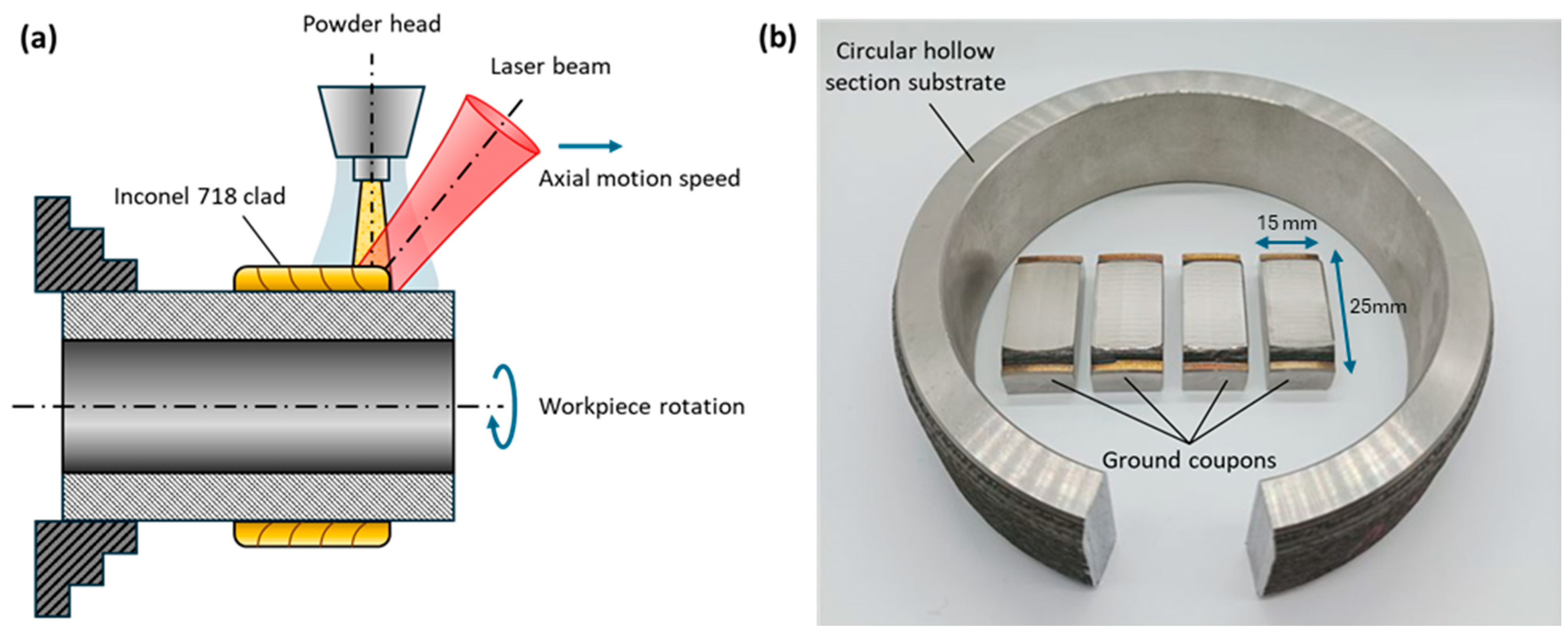
Figure 1. (a) Experimental off-axis setup for laser cladding; and (b) the as-cladded CHS substrate along with sectioned and ground specimen coupons.
Metals 15 01190 g001
Figure 2. (a) Ball burnishing experimental setup, and (b) schematic of the burnishing mechanism showing deformation under applied pressure.
Metals 15 01190 g002
Figure 3. Ball burnishing path strategies used to generate four surface conditions: (a) Ground (no burnishing), (b) BB-Longitudinal (burnishing parallel to the cladding direction), (c) BB-Transverse (burnishing perpendicular to the cladding direction), and (d) BB-Crosshatch (burnishing in two orthogonal directions).
Metals 15 01190 g003
Figure 4. Schematics of typical surface profiles of Inconel® 718 cladding: (a) as-cladded surface showing overlapping laser-deposited beads, (b) ground surface with fine micro-grooves from abrasive finishing, and (c) ball-burnished surface exhibiting deformation bands and valleys aligned with the burnishing path.
Metals 15 01190 g004
Figure 5. (a) Top surface and (b) cross-sectional hardness mapping protocol, showing the distribution of traces of indents on the surface.
Metals 15 01190 g005
Figure 6. Surface topographies and roughness profiles of laser cladded Inconel 718: (a) ground, (b) BB-longitudinal, (c) BB-transverse, and (d) BB-crosshatch.
Metals 15 01190 g006
Figure 7. Comparison of surface roughness parameters for Inconel 718 cladded surfaces: (a) areal parameters Sa and Sz, and (b) profile parameters Ra and Rz, across ground and BB-treated conditions.
Metals 15 01190 g007
Figure 8. SEM micrographs of Inconel 718 surfaces: (a) Ground, (b) BB-Longitudinal, (c) BB-Transverse, and (d) BB-Crosshatch.
Metals 15 01190 g008
Figure 9. Kernel Average Misorientation (KAM) maps for (a) Ground, (b) BB-Longitudinal, (c) BB-Transverse, (d) BB-Crosshatch surface conditions, (e) Comparison of average KAM values across treatments, and (f) Estimated dislocation densities derived from EBSD data for each condition.
Metals 15 01190 g009
Figure 10. IPF maps overlaid with grain boundaries for (a) Ground, (b) BB-Longitudinal, (c) BB-Transverse, and (d) BB-Crosshatch conditions; (e) comparison of LAGB and HAGB fractions.
Metals 15 01190 g010
Figure 11. Contour mapping of surface hardness array for (a) Ground, (b) BB-Longitudinal, (c) BB-Transverse, (d) BB-Crosshatch conditions; (e) comparison of mean surface hardness along X-direction; (f) comparison of overall surface hardness. Image shown at the top of the figure shows the mapping of indentations on the surface.
Metals 15 01190 g011
Figure 12. Cross-sectional hardness profiles along the depth from the top surface for (a) Ground, (b) BB-Longitudinal, (c) BB-Transverse, and (d) BB-Crosshatch conditions.
Metals 15 01190 g012
Figure 13. (a) impact test protocol, (b) representative imprint of indent shape due to impact, and (c) comparison of indent volume and maximum depth.
Metals 15 01190 g013
Figure 14. (a) Pin-on-disc test sample and track (b) comparison of worn volume and CoF and (c) SEM images of the worn surfaces for all four treated samples.
Metals 15 01190 g014
Figure 15. Comparison of coefficient of frictions (CoFs) for all four treated samples.
Metals 15 01190 g015
Figure 16. Tafel polarization curves for ground and BB-treated Inconel 718 specimens.
Metals 15 01190 g016
Figure 17. Optical microscopic images of the corroded surfaces after potentiodynamic tests for (a) Ground, (b) BB-Longitudinal, (c) BB-Transverse, and (d) BB-Crosshatch conditions.
Metals 15 01190 g017
Table 1. Chemical Composition of Inconel 718 Powder Feedstock (wt.%).
MaterialChemical Composition (wt.%)
CCrMoNiTiAlNbBFe
Inconel 718
Powder Feedstock
0.02183Bal.0.950.550.00318.5
Table 2. Summary of electrochemical corrosion tests.
SpecimenCorrosion
Potential, Ecorr
(mV vs. SCE)
Corrosion Density, Icorr (mA/cm2)Pitting Potential, Epit (mV vs. SCE)Polarization
Resistance, Rp (MΩ·cm2)
Open Circuit
Potential, OCP (mV vs. SCE)
Ground−109 ± 430.017 ± 0.0011164 ± 161.05 ± 0.2−61 ± 35
BB-Longitudinal13 ± 880.021 ± 0.0031165 ± 80.63 ± 0.214 ± 30
BB-Transverse−73 ± 630.015 ± 0.0071158 ± 111.23 ± 0.01−77 ± 82
BB-Crosshatch−43 ± 450.020 ± 0.0041145 ± 160.53 ± 0.2−35 ± 37
Disclaimer/Publisher’s Note: The statements, opinions and data contained in all publications are solely those of the individual author(s) and contributor(s) and not of MDPI and/or the editor(s). MDPI and/or the editor(s) disclaim responsibility for any injury to people or property resulting from any ideas, methods, instructions or products referred to in the content.