Abstract
In this study, ultrasonic-assisted friction stir lap welding (UaFSLW) successfully joined AA2024 and AZ31, and the weld performance was systematically investigated. The beneficial effect of ultrasonic assistance was pronounced under cold welding parameters (using a low rotational speed, 400 rpm); compared with conventional FSLW, the material flow during UaFSLW was significantly enhanced. This led to grain refinement (~20%, 0.4 μm) in the nugget zone and an elongated Al/Mg bonding interface (3.3 mm). Additionally, the inter-diffusion of Al and Mg atoms was accelerated, resulting in a continuous intermetallic compound (IMC) layer. As a result, the UaFSLW joint exhibited a tensile shear load 210 N (±5 N) higher than that of a conventional FSLW joint, attributable to enhanced metallurgical and mechanical bonding. By contrast, employing hot welding parameters (using a high rotational speed, 1200 rpm) resulted in grain growth and a thickened IMC layer in the nugget zone, while simultaneously eliminating the hook structure. The coarsening of microstructures, coupled with diminished mechanical bonding, collectively caused the tensile shear load of an FSLW joint to drop to 80% of the value obtained with cold welding parameters. Furthermore, under hot welding parameters, the ultrasonic assistance had a limited impact on microstructures, with the only notable improvement being an elongated Al/Mg bonding interface, which partially compensated for the loss in tensile shear load.
1. Introduction
There is a growing demand for components fabricated from dissimilar aluminum (Al) and magnesium (Mg) alloys as lightweight solutions in the automotive and aerospace industries, enabling a potential reduction in CO2 emissions [1]. However, a major challenge in the conventional fusion or diffusion welding of Al and Mg alloys is the excessive formation of a brittle intermetallic compound (IMC) layer at the joint, which significantly compromises the mechanical properties [2,3,4]. Recently, friction stir welding (FSW), a solid-state joining technique, has been employed to produce dissimilar Al/Mg joints with a high strength. This improved strength is attributable to the relatively low and controllable weld heat input, coupled with severe plastic deformation and a high strain rate within the nugget zone. These conditions effectively suppress the formation of a brittle IMC layer [5,6,7,8]. Friction stir lap welding (FSLW), a derivative technique of FSW, has also emerged as a prominent method for joining Al and Mg alloys [9,10].
The quality of dissimilar Al/Mg FSLW joints is governed by both the thickness of an IMC layer along the Al/Mg bonding interface and the morphology of the hook structure [11,12]. Given that eutectic reactions in the Al-Mg system occur at 450 °C and 437 °C, the formation of an IMC layer is inevitable during FSLW, even at a reduced temperature [10]. A thick IMC layer promotes crack nucleation and propagation, leading to a reduction in joint strength [13,14]. Consequently, controlling the IMC layer thickness is essential, with studies showing that a continuous yet thin layer (1–2 μm) is optimal for improving dissimilar Al/Mg joints as it enhances metallurgical bonding [15,16]. Although metallurgical bonding from the IMC layer is crucial for the strength of a dissimilar Al/Mg FSLW joint, the mechanical bonding provided by the hook structure is equally important. While the formation of this hook structure enhances mechanical interlocking, its height must be carefully controlled, as an excessively high hook reduces the effective sheet thickness, thereby decreasing the overall joint strength [17].
However, optimizing both the thickness/continuity of the IMC layer and the morphology of the hook structure simultaneously is difficult through the conventional welding parameters adjustment. For instance, Zhai et al. [18] reported that increasing the rotational speed (from 800 rpm to 1000 rpm) was beneficial for reducing the height of the hook structure. On the other hand, the associated high heat input concurrently thickened the IMC layer, ultimately compromising the strength of the dissimilar Al/Mg FSLW joint. As Zhao et al. [19] investigated, increasing the pin length of the stir tool enhanced the material mixing, which promoted the hook formation but also led to a thickening of IMC layers. By reducing the plunge depth of the stir tool, Li et al. [20] controlled the hook height and created a wavy lap interface. This approach significantly enhanced the mechanical interlocking while disrupting the continuity of the IMC layer. Therefore, advancing FSLW methods is necessary to further improve the quality of dissimilar Al/Mg joints.
The recent proposal of ultrasonic-assisted FSLW (UaFSLW) aims to improve the weld performance of dissimilar Al/Mg joints, and thereby broaden the processing windows to facilitate their industrial adoption. Published studies demonstrate that (I) by reducing the barrier to dislocation motion, the ultrasonic assistance induces acoustic softening, which enhances the material flow and alters the hook structure morphology [21]; (II) ultrasonic assistance subjects the material to a high strain rate and intense dynamic deformation during UaFSLW, which consequently suppresses the excessive formation of the IMC layer [22]. Up to now, the demonstrated efficacy of this method extends to joining dissimilar alloys beyond Al/Mg, such as Al/Ti [23]. Nevertheless, most published studies are predominantly focused on verifying the effectiveness of ultrasonic assistance in improving FSLW quality, while overlooking the interplay between ultrasonic and welding parameters.
It remains unclear whether ultrasonic assistance is equally suitable for both cold and hot welding parameters, as well as whether its efficiency is consistent across these different conditions. In the present work, both conventional FSLW and UaFSLW were employed to join dissimilar Al and Mg under two typical weld conditions (i.e., cold and hot welding parameters), and the microstructural evolution and mechanical properties were systematically analyzed. We hypothesize that ultrasonic assistance will be more pronounced under cold welding parameters. In contrast, under hot welding parameters, its effects are expected to be diminished because the material flow becomes sufficient, thereby mitigating the acoustoplastic effect. This experimental design aimed to systematically investigate the influence of ultrasonic assistance on weld performance, identify its suitable application scenarios, and evaluate its efficiency.
2. Materials and Methods
In this study, 2 mm thick rolled plates of AA2024 and AZ31 were selected as the base metals, with their nominal chemical compositions provided in Table 1. The initial hardness of AA2024 and AZ31 were 145 HV and 75 HV, respectively. The FSLW setup is illustrated in Figure 1a, while detailed views of the ultrasonic source are presented in Figure 1b,c. The ultrasonic source was mounted below the back-plate (Figure 1b), with its head inserted into the back-plate through a pre-drilled hole (Figure 1c). The ultrasonic head had a diameter of 38 mm, and the ultrasonic parameters were maintained constant at 300 W power, 20 kHz frequency, and 20 μm amplitude. The AA2024 and AZ31 plates were machined to dimensions of 150 mm × 70 mm × 2 mm and arranged in a lap joint configuration, where the AA2024 plate was placed over the AZ31 plate, as shown in Figure 1d. A H13 steel stir tool was used for FSLW. It had an 8 mm diameter shoulder and a 2 mm long conical pin with root and tip diameters of 4.5 mm and 3.5 mm, respectively. Two distinct sets of welding parameters were employed: one for a cold weld and the other for a hot weld. The weld heat input can be expressed by “rotational speed/weld speed” [14]. The cold welding parameters, characterized by a low heat input, used a rotational speed of 400 rpm and a weld speed of 50 mm/min. In contrast, the hot welding parameters, representing a high heat input, were set at 1200 rpm and 50 mm/min. During FSLW, the distance from the ultrasonic source to the weld centerline was maintained at 30 mm and the tool tilt angle was set at 1°, with a plunge depth of 0.2 mm. For simplicity, the joints produced by FSLW and UaFSLW under cold welding parameters were designated as FSLW-C and UaFSLW-C, respectively, while those produced under hot welding parameters were designated as FSWL-H and UaFSLW-H.

Table 1.
Nominal chemical compositions (wt. %) of AA2024 and AZ31 used in this study.
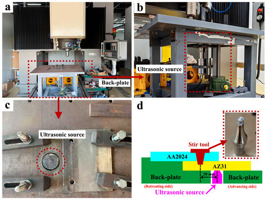
Figure 1.
(a) FSLW setup, (b) ultrasonic source, (c) head of ultrasonic source, (d) schematic of FSLW/UaFSLW.
A microstructural analysis of the dissimilar Al/Mg FSLW joints was conducted with an optical microscope (OM, Olympus DSX-500, Tokyo, Japan) and a scanning electron microscope (SEM, FEI Quanta-600, Portland, OR, USA). Samples for OM observation were first mechanically ground and polished, followed by etching with Keller’s reagent (HF:HCL:HNO3:H2O volume ratio = 2:3:5:90). The etch time was 5–10 s. In contrast, samples for SEM observation were solely ground and polished to prevent the dislodgment of second-phase particles during etching. SEM observation was performed in secondary electron mode. The grain size and the fraction of high-angle grain boundaries (HAGBs) in the nugget zone were characterized by electron backscatter diffraction (EBSD, FEI Quanta-600). Following electro-polishing in a 10% perchloric acid–ethanol solution, EBSD mapping was conducted with a 0.2 μm step size. The scanning area was 150 μm × 100 μm, the map location was in the middle of the nugget zone along the AA2024 plate, the step size rationale was 0.1, and the low-angle grain boundaries (LAGBs, 2–10°) were depicted in white and HAGBs (>10°) in black.
The mechanical properties of dissimilar Al/Mg FSLW joints were evaluated by Vickers hardness testing and tensile shear testing. The hardness distribution across the joint was measured on an HV-1000Z tester (HV, Shangcai-1000Z, Shanghai, China) along a line at the mid-thickness of the upper AA2024 plate, spanning from the retreating side (RS) to the advancing side (AS). Each hardness traverse consisted of 30–40 indentations spaced 0.5 mm apart, applied with a 50 gf load and a 5 s dwell time. Tensile shear specimens, with a gauge dimension of 40 mm × 10 mm, were sectioned perpendicular to the weld direction. The tensile shear testing was performed at room temperature with a constant crosshead speed of 1.5 mm/min. The reported peak tensile shear load represented the average of three tests for each joint condition. The elongation was determined according to the following standard formula: (final length at fracture − initial gauge length)/initial gauge length. The fracture surfaces were subsequently examined using SEM to analyze the failure behavior. The flowchart summarizing the experimental procedure is shown in Figure 2.
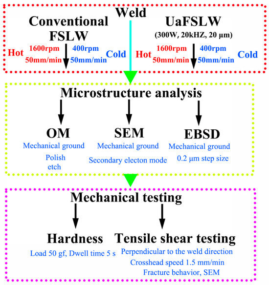
Figure 2.
Flowchart summarizing the experimental procedure.
3. Results and Discussion
The initial microstructures of the base metals are shown in Figure 3. Both AA2024 and AZ31 exhibit coarse grains (Figure 3a,b), along with the presence of second-phase particles (Figure 3c,d). The EDS analysis reveals that these particles are rich in Fe-Mn-Si in AA2024 and rich in Al-Mn in AZ31. Previous studies by Farajollahi et al. [24] and Manjhi et al. [25] correlate these phases in AA2024 and AZ31 to Al(Cu, Mn, Fe, Si) and Al8Mn5, respectively. Moreover, the quantity of second-phase particles in AA2024 is greater than that in AZ31, which can likely be attributed to the relatively lower alloying content of AZ31, as indicated in Table 1.
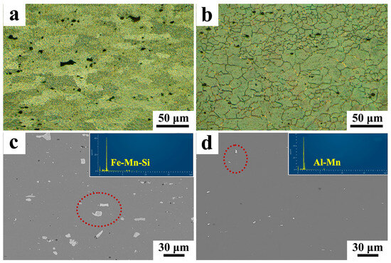
Figure 3.
Microstructures of base metals: grains in (a) AA2024 and (b) AZ31; second-phase particles in (c) AA2024 and (d) AZ31.
Figure 4 presents the cross-sections of all dissimilar Al/Mg joints, with detailed morphological analyses of their Al/Mg bonding interfaces provided. In the conventional FSLW joint produced with cold welding parameters (Figure 4a), a distinct hook structure is observed on the AS, and the Al/Mg bonding interface measures 3.1 mm in length (Figure 4b). The formation of the hook structure is related to the material flow behaviors in the nugget zone [26]: initially, AA2024 flows downward and accumulates near the pin tip of the stir tool; subsequently, the accumulated AA2024 forces the underlying AZ31 to flow upward, thereby forming the hook structure on the AS. In contrast, the acoustoplastic effect induced by the ultrasonic assistance enhances the material flow during FSLW [27,28]; this intensified flow results in a wavy Al/Mg bonding interface in the UaFSLW-C joint (Figure 4c) and increases the interface length to 3.3 mm (Figure 4d). Additionally, the hook structures in both the FSLW-C and UaFSLW-C joints are low in height (less than 0.3 mm), which guarantees a sufficient effective sheet thickness. Differently, a typical onion ring structure is observed in the nugget zone of FSLW-H and UaFSLW-H joints (Figure 4e,g), demonstrating enhanced material flowability due to the application of hot welding parameters [29]. Meanwhile, the hook structure is eliminated, leading to a relatively flat Al/Mg bonding interface. The interface length is 2.8 mm in the FSLW-H joint and increases to 3.5 mm with ultrasonic assistance (Figure 4f,h). This increase in interface length is driven by the intensified material flow because of ultrasonic assistance, which thereby enlarges the bonding area between Al and Mg.
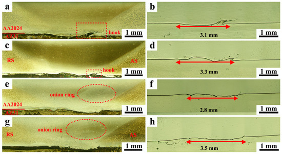
Figure 4.
Cross-sectional views of (a) FSLW-C joint, (c) UaFSLW-C joint, (e) FSLW-H joint, (g) UaFSLW joint and Al/Mg bonding interfaces of (b) FSLW-C joint, (d) UaFSLW-C joint, (f) FSLW-H joint, (h) UaFSLW-H joint.
Figure 5 shows the SEM morphologies of the hook structure in all dissimilar Al/Mg joints, where the secondary electron contrast is characterized by a brighter appearance in AA2024 and a darker appearance in AZ31. For the FSLW-C joint (Figure 5a), the AZ31 base metal extends linearly into AA2024, exhibiting a nearly straight profile. In contrast, the hook structure in the UaFSLW-C joint exhibits pronounced bending, leading to a reduction in its height (Figure 5b). This curved morphology results from ultrasonically induced material softening [30], which facilitates the initial penetration of AZ31 into AA2024 and its subsequent deformation in the nugget zone. The difference in hook morphology between the FSLW-H and UaFSLW-H joints is minimal, with both joints exhibiting a suppressed hook structure (Figure 5c,d). The use of hot welding parameters further softens AZ31, thereby impeding its penetration into AA2024 and consequently suppressing hook formation. In addition, the similar hook morphology of FSLW-H and UaFSLW-H joints indicates that the softening effect induced by ultrasonic assistance becomes negligible when the material is already sufficiently softened by other means.
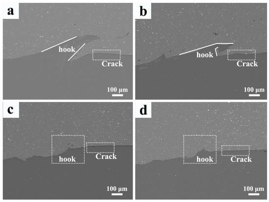
Figure 5.
Hook structures of Al/Mg bonding interfaces in the (a) FSLW-C joint, (b) UaFSLW-C joint, (c) FSLW-H, (d) UaFSLW-H joint.
Figure 6 presents the morphologies of the Al/Mg bonding interface both within and outside the hook structure. The mixing of Al and Mg within the hook structure of the FSLW-C joint is evidenced by the presence of blocky AA2024 fragments stirred into the AZ31 matrix. Meanwhile, an initial crack is observed outside the hook structure (Figure 6a). The putative IMCs consistent with Al–Mg phases (i.e., Al3Mg2 and Al12Mg17) are formed due to the thermal–mechanical conditions of FSLW [31], exhibiting an intermediate contrast distinct from the bright Al and dark Mg matrices. The initial crack in the FSLW-C joint is located along the Al/Mg bonding interface but shows no such intermediate contrast. This indicates that the initial crack is induced by the weak interfacial bonding between Al and Mg, rather than by the fracture of the IMC layer. Differently, it is observed in the UaFSLW-C joint that the initial crack forms through the IMC layer (exhibiting intermediate contrast) and is terminated by the hook structure (Figure 6b). Under hot welding parameters, the mixing of Al and Mg is enhanced, the blocky AZ31 fragments are replaced by fine particles, and the initial crack is caused by the fracture of the IMC layer (Figure 6c,d).
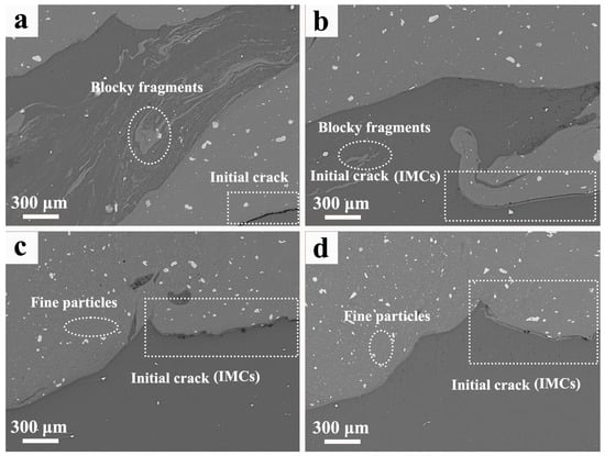
Figure 6.
Initial cracks of Al/Mg bonding interfaces in the (a) FSLW-C joint, (b) UaFSLW-C joint, (c) FSLW-H joint, (d) UaFSLW-H joint.
The morphologies of the Al/Mg bonding interface in the nugget zone are shown in Figure 7. For the FSLW joint (Figure 7a), the IMC layer is relatively thin and discontinuous. As revealed by EDS line scanning (Figure 8a), its thickness measures less than 1 μm. Under the cold welding parameters, the low heat input is inadequate to support a significant Al-Mg reaction, thereby preventing the substantial formation of the IMC layer [32]. In comparison, the IMC layer in the UaFSLW-C joint becomes thick and continuous, with an average thickness of approximately 1.5 μm (Figure 8b). Furthermore, numerous fine particles are distributed along the Al/Mg bonding interface, suggesting enhanced mixing between Al and Mg. Ultrasonic assistance introduces two primary effects during FSLW: (I) the acoustoplastic effect [27,28], (II) the fast diffusion effect [33]. For the UaFSLW-C joint, the first effect enhances material flow, thereby breaking the initial Al/Mg fragments into fine particles. As for the second effect, ultrasonic makes dislocation operation easier. During UaFSLW, dislocations proliferate more, reducing the formation energy of intermetallic compounds and promoting atomic diffusion, accelerating IMC layer formation [34], and consequently leading to the growth of the IMC layer. The use of hot welding parameters further increases the heat input, thereby promoting the growth of the IMC layer. As a result, the IMC layer thickness in the FSLW-H joint reaches 2–2.5 μm (Figure 7c and Figure 8c). However, the effect of ultrasonic assistance on the evolution of the IMC layer becomes less pronounced, as evidenced by the similar IMC layer thickness observed in the UaFSLW-H joint (Figure 7d and Figure 8d). The diffusion coefficient exhibits an Arrhenius-type dependence on temperature [34]. The application of hot welding parameters boosts the FSLW peak temperature [35], which promotes the diffusion coefficient and thereby ensures a sufficient diffusion process in the FSLW-H and UaFSLW-H joints. It can thus be inferred that the fast diffusion effect induced by the ultrasonic is no longer dominant when the diffusion process becomes sufficient.
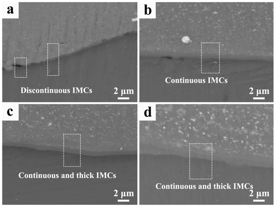
Figure 7.
IMC layers along the Al/Mg bonding interfaces of (a) FSLW-C joint, (b) UaFSLW-C joint, (c) FSLW-H joint, (d) UaFSLW-H joint.
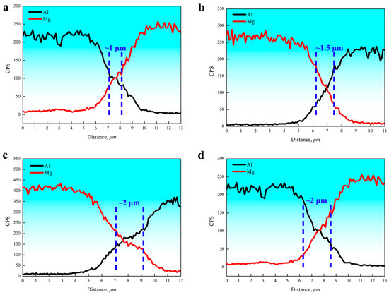
Figure 8.
EDS line scans across the IMC layers in the (a) FSLW-C joint, (b) UaFSLW-C joint, (c) FSLW-H joint, (d) UaFSLW-H joint.
The thickness of the IMC layer was measured at five random points in Figure 7, and Table 2 shows the variation in IMC thickness for all joints. It can be seen that the thickness of the IMC layer is non-uniform, while the average thickness of the FSLW-H joint and the UaFSLW-H joint is still thicker than that of the FSLW-C joint and the UaFSLW-C joint. The non-uniform thickness is related to the heterogeneous deformation process of FSLW [36].

Table 2.
Variation in IMC layer for all joints.
During FSLW, the second-phase particles in the nugget zone are directly stirred and fragmented into fine particles by the tool (Figure 9a–d). It can be concluded that neither ultrasonic assistance nor the welding parameters effectively enhance particle fragmentation, as evidenced by the similar average particle size across all dissimilar Al/Mg joints. This finding can be explained by the principle that particles below a critical diameter are resistant to further fragmentation [37]. The histograms of second-phase particle sizes for each condition have also been included in Figure 9, and it can be seen that the size of the secondary-phase particles is concentrated in the range of 2 to 4 μm.
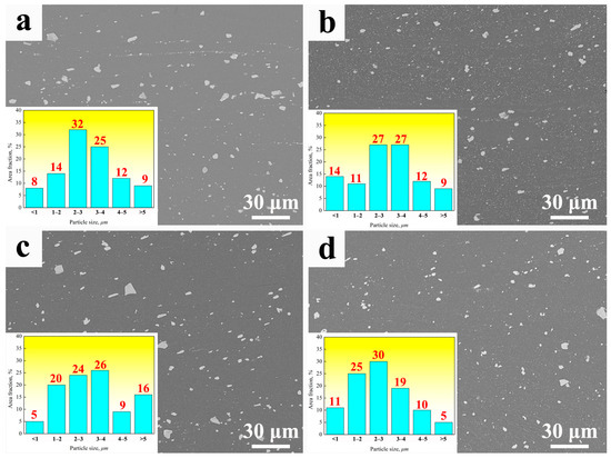
Figure 9.
Second-phase particles in the nugget zone of (a) FSLW-C joint, (b) UaFSLW-C joint, (c) FSLW-H joint, (d) UaFSLW-H joint.
As shown in Figure 10, the grains in the nugget zones of all dissimilar Al/Mg joints are fine and equiaxed. This microstructure results from dynamic recrystallization (DRX), which occurs during FSLW and leads to grain refinement [38]. The grain size is governed by both the heat input and the material’s strain rate [39,40]. The cold welding parameters reduce the heat input, thereby suppressing grain growth in the nugget zone and resulting in an average grain size of 2.0 μm in the FSLW-C joints (Figure 10a). The application of ultrasonic assistance enhances the material flow, thereby increasing the strain rate during FSLW, which in turn reduces the grain size to 1.5 μm in the UaFSLW-C joint (Figure 10b). In contrast, the hot welding parameters increase the heat input, which leads to grain growth in the nugget zones of the FSLW-H and UaFSLW-H joints. The average grain size of the above joints is about 2.6 μm (Figure 10c,d). Compared with the FSLW-H joint, ultrasonic assistance does not produce further grain refinement in the UaFSLW-H joint. This is attributed to the hot welding parameters, which sufficiently soften the material, making it highly fluid and raising the strain rate to its upper limit [41]. Consequently, additional grain refinement from ultrasonic assistance is minimal. In addition, Kernel Average Misorientation (KAM) analysis indicates a relatively low dislocation density in the nugget zone, which is attributed to the consumption of dislocations by DRX [42]. This is consistent with the observed near-complete DRX in all dissimilar Al/Mg joints, evidenced by a high fraction of high-angle grain boundaries (HAGBs) exceeding 90%.
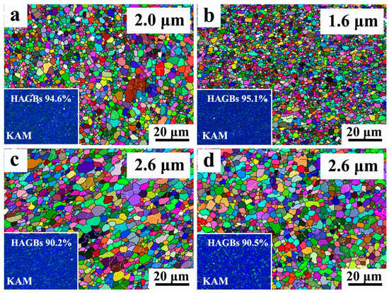
Figure 10.
Grain morphology in the nugget zones of (a) FSLW-C joint, (b) UaFSLW-C joint, (c) FSLW-H joint, (d) UaFSLW-H joint.
Figure 11a presents the hardness profile across the dissimilar Al/Mg joint in the upper AA2024 plate, and all joints are characterized by a W-shaped hardness distribution. The reduced hardness in the nugget zone, compared with the base metal, originates from the dissolution or coarsening of the strengthening Al2CuMg precipitates during FSLW [43]. The hardness is also lowered by the relatively low dislocation density in the nugget zone. The average hardness values in the nugget zone are summarized in Figure 11b. Under cold welding parameters, the hardness increases from 119 HV in the FSLW-C joint to 123 HV in the UaFSLW-C joint, which is ascribed to the grain refinement. Conversely, the hardness decreases to 114 HV in the FSLW-H joint due to the grain growth under hot welding parameters. The UaFSLW-H joint exhibits a similar hardness to the FSLW-H joint, consistent with their comparable microstructures. It should be noted that while the grain refinement provides some strengthening, its effect is still insufficient to counteract the overall softening resulting from the loss of precipitation and dislocation strengthening. This result is consistent with the findings of Feng et al. [44].
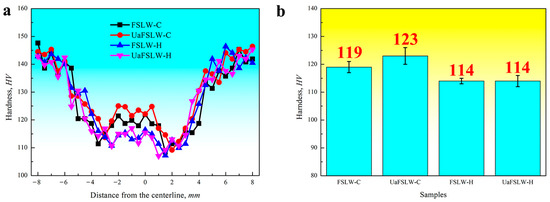
Figure 11.
(a) Hardness distributions and (b) average hardness of nugget zones in all dissimilar Al/Mg joints.
As shown in Figure 12a, the tensile shear properties of dissimilar Al/Mg joints are consistent with the hardness trends, showing improved performance under cold welding parameters. The FSLW-C joint has a tensile shear load of 1.77 kN and elongation of 4.7%. With ultrasonic assistance, these values rise to 1.98 kN and 5.1% for the UaFSLW-C joint. Under hot welding parameters, a marked reduction in performance is observed. The tensile shear load decreases to 1.41 kN for the FSLW-H joint and 1.53 kN for the UaFSLW-H joint, accompanied by lower elongations of 2.5% and 3.3%, respectively. (Figure 12b). To investigate the fracture behavior, the fracture surface and its composition were examined, as shown in Figure 13. All tensile shear specimens fractured along the Al/Mg bonding interface in the nugget zone (Figure 13a–d). The fracture surfaces appear relatively flat and lack dimples, indicating brittle failure (Figure 13e–h). Furthermore, the detection of both Al and Mg on these surfaces confirms that the fracture propagates through the IMC layer at the Al/Mg bonding interface.
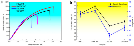
Figure 12.
(a) Tensile shear test curves and (b) tensile shear properties of all dissimilar Al/Mg joints.

Figure 13.
Fracture analysis of (a,e) FSLW-C joint, (b,f) UaFSLW-C joint, (c,g) FSLW-H joint, (d,h) UaFSLW-H joint.
The fracture mechanisms of the dissimilar Al/Mg joint in this study are shown in Figure 13. Under cold welding parameters, the Al/Mg bonding interface in the FSLW and UaFSLW joints comprises two distinct regions: one controlled by the hook structure and the other by the IMC layer. Conversely, under hot welding parameters, the Al/Mg bonding interface in the FSLW and UaFSLW joints is controlled solely by the IMC layer due to the limited development of the hook structure (Figure 5). The initial crack outside the hook structure serves as a common fracture initiation site (Figure 6); however, the crack follows divergent propagation paths under cold versus hot welding parameters. The fracture mechanism under cold welding parameters is characterized by crack propagation through the hook structure and the IMC layer (Figure 14a). The presence of the hook structure is thus critical, as it enhances mechanical interlocking and increases the interfacial bonding length, thereby contributing to simultaneous mechanical and metallurgical bonding. This combined strengthening mechanism explains the relatively high tensile shear properties of FSLW-C joints. Furthermore, the application of ultrasonic assistance transforms the thin and discontinuous IMC layer (as in the FSLW-C joint) into a continuous one, while also extending the bonding interface from 3.1 mm to 3.3 mm. This enhanced metallurgical bonding accounts for the superior tensile shear properties of the UaFSLW-C joint. In contrast, under hot welding parameters, the elimination of the hook structure results in a flat fracture path. As a result, cracks can propagate unimpeded through the IMC layer, as illustrated in Figure 14b. The mechanical bonding in the FSLW-H joint is limited and further compromised by a short bonding interface (2.8 mm), collectively leading to a deteriorated weld performance. Compared with the FSLW-H joint, the UaFSLW-H joint benefits from an elongated IMC layer that strengthens the metallurgical bonding. This improvement, however, is offset by excessive layer thickening, which embrittles the joint [45] and results in a inferior strength and ductility relative to the FSLW-C/UaFSLW-C joints.
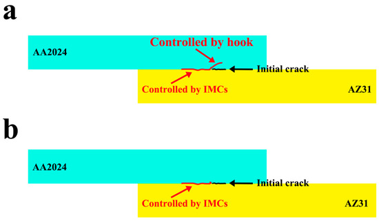
Figure 14.
Fracture mechanisms of dissimilar Al/Mg joint (a) with and (b) without hook structure.
We suggest that the above results prove the efficacy of ultrasonic assistance in improving weld performance. This work further pinpoints cold welding parameters as the ideal scenario for its application, enabling the FSLW process to capitalize on the acoustoplastic and rapid diffusion effects.
4. Conclusions
The FSLW/UaFSLW performance of dissimilar Al/Mg joints using cold and hot welding parameters was investigated, and the following results were summarized:
- (1)
- Under cold welding parameters, Al and Mg were bonded through the formation of an IMC layer and a hook structure. In the conventional FSLW joint, the Al/Mg bonding interface measured 3.1 mm in length, and the IMC layer was relatively thin and discontinuous. In contrast, the application of ultrasonic assistance enhanced material flow, increased the length of the Al/Mg bonding interface to 3.3 mm, and resulted in a continuous IMC layer. Moreover, compared with the conventional FSLW joint, the grains in the nugget zone were refined under ultrasonic assistance, which could be attributed to the increased strain rate. The average grain size in the nugget zone decreased from 2.0 μm in the FSLW-C joint to 1.6 μm in the UaFSLW-C joint.
- (2)
- Under hot welding parameters, the IMC layer exhibited an increase in thickness, and the hook structure was eliminated due to excessive heat input and material softening during FSLW. Concurrently, grain growth occurred in the nugget zone. The average grain size and thickness of the IMC layer for the FSLW-H and UaFSLW-H joints were 2.6 μm and 2 μm, respectively. The beneficial effect of ultrasonic assistance on the microstructures (i.e., the grain size and IMC layer thickness) was limited: the enhancement was confined primarily to an elongation of the Al/Mg bonding interface, which increased from 2.8 mm in the FSLW-H joint to 3.5 mm in the UaFSLW-H joint.
- (3)
- The hardness in the nugget zone of all dissimilar Al/Mg joints was lower than that of the Al base metal owing to the loss of dislocation and precipitation strengthening. Among all joints, the UaFSLW joint produced with cold welding parameters showed the highest hardness in the nugget zone (123 HV), attributable to grain refinement. Consistent with the hardness results, the tensile shear load also increased when cold welding parameters were applied: the conventional FSLW joint under hot welding parameters had a maximum tensile shear load of 1.41 kN, whereas the UaFSLW joint produced with cold welding parameters reached a higher load of 1.98 kN.
- (4)
- The initial crack was located outside the hook structure. It propagated across the hook and subsequently extended through the Al/Mg bonding interface. Under cold welding parameters, the conventional FSLW joint possessed a hook structure that impeded crack propagation, but its thin and discontinuous IMC layer limited the bonding strength. Ultrasonic assistance improved this by elongating the Al/Mg bonding interface and forming a continuous IMC layer, enhancing the tensile shear properties of the UaFSLW-C joint. Under hot welding parameters, the hook structure was eliminated, weakening the mechanical interlocking between Al and Mg, while the thickened IMC layer further softened the FSLW joint. Although ultrasonic assistance elongated the Al/Mg bonding interface and partially recovered the load/elongation, the overall properties remained inferior.
It should be noted that an economic assessment was not included in this study. It should also be noted that the incorporation of ultrasonic equipment may lead to an increase in overall cost. This study lacked direct temperature and torque measurements, and the intermetallic compound (IMC) phases were inferred indirectly. Therefore, further work is needed on these aspects. In addition, future research should focus on in situ thermal/force monitoring, phase-resolved characterization, the parametric mapping of ultrasonic power/frequency, and interface engineering (e.g., using a Zn interlayer) under cold welding parameters. Furthermore, the failure mechanisms of FSLW joints under shear loading, dictated by a near-zero hydrostatic stress state that promotes slip, remain to be fully elucidated. A deeper exploration of this fracture behavior is highly recommended. The impact of ultrasonic assistance on residual stress and fatigue performance should also be investigated in the future.
Author Contributions
Conceptualization, Y.C. and Q.H.; methodology, R.L. and J.T.; investigation, R.L. and J.T.; resources, Y.C.; writing—original draft preparation, R.L. and J.T.; writing—review and editing, Y.C. and Q.H.; supervision, Y.C.; project administration, Y.C.; funding acquisition, Y.C. All authors have read and agreed to the published version of the manuscript.
Funding
This research was funded by the Opening Foundation of Key Laboratory of Advanced Manufacture Technology for Automobile Parts, Ministry of Education (grant number 2023KLMT05), the Guangdong Basic and Applied Basic Research Foundation (grant number 2025A1515012322), the fund of State Key Laboratory of Solidification Processing (grant number SKLSP202408), the Open Research Fund of State Key Laboratory of Precision Manufacturing for Extreme Service Performance (grant number Kfkt2024-03), and the Scientific Research Funding of Educational Department of Liaoning Province (grant number LJKMZ20220346).
Data Availability Statement
The original contributions presented in this study are included in the article. Further inquiries can be directed to the corresponding author.
Conflicts of Interest
The authors declare no conflicts of interest.
References
- Muhammad, N.A.; Geng, P.H.; Wu, C.S.; Ma, N.S. Unravelling the ultrasonic effect on residual stress and microstructure in dissimilar ultrasonic-assisted friction stir welding of Al/Mg alloys. Int. J. Mach. Tools Manuf. 2023, 186, 104004. [Google Scholar] [CrossRef]
- Liu, F.; Wang, H.; Liu, L. Characterization of Mg/Al butt joints welded by gas tungsten arc filling with Z-29.5Al-0.5Ti filler metal. Mater. Charact. 2014, 90, 1–6. [Google Scholar] [CrossRef]
- Varmazyar, J.; Khodaer, M. Diffusion bonding of aluminum-magnesium using cold rolled copper interlayer. J. Alloys Compd. 2019, 773, 838–843. [Google Scholar] [CrossRef]
- Bannour, S.; Abderrazak, K.; Mattei, S.; Masse, J.E.; Autric, M.; Mhiri, H. The influence of position in overlap joints of Mg and Al alloys on microstructure and hardness of laser welds. J. Laser Appl. 2013, 25, 032001–032008. [Google Scholar] [CrossRef]
- Verma, J.; Taiwade, R.V.; Sapate, S.G.; Patil, A.P.; Dhoble, A.S. Evaluation of microstructure, mechanical properties and corrosion resistance of friction stir-welded aluminum and magnesium dissimilar alloys. J. Mater. Eng. Perform. 2017, 26, 4738–4747. [Google Scholar] [CrossRef]
- Boccarusso, L.; Astarita, A.; Carlone, O.; Scherillo, F.; Rubino, F.; Squillace, A. Dissimilar friction stir lap welding of AA6082-Mg AZ31: Force analysis and microstructure evolution. J. Manuf. Process. 2019, 44, 376–388. [Google Scholar] [CrossRef]
- Zhao, Y.; Huang, L.; Zhao, Z.; Yan, K. Effect of travel speed on the microstructure of Al-to-Mg FSW joints. Mater. Sci. Technol. 2016, 32, 1025–1034. [Google Scholar] [CrossRef]
- Simonconi, M.; Forcellese, A. Effect of the welding parameters and tool configuration on micro- and macro-mechanical properties of similar and dissimilar FSWed joints in AA5754 and AZ31 thin sheets. Mater. Des. 2012, 41, 50–60. [Google Scholar] [CrossRef]
- Niu, S.Y.; Ji, S.D.; Yan, D.J.; Meng, X.C.; Xiong, X.H. AZ31B/7075-T6 alloys friction stir lap welding with a zinc interlayer. J. Mater. Process. Technol. 2019, 263, 82–90. [Google Scholar] [CrossRef]
- Chen, Y.C.; Nakata, K. Friction stir lap joining aluminum and magnesium alloys. Scr. Mater. 2008, 58, 433–436. [Google Scholar] [CrossRef]
- Tan, S.; Zheng, F.Y.; Chen, J.; Han, J.Y.; Wu, Y.J.; Peng, L.M. Effects of process parameters on microstructure and mechanical properties of friction stir lap linear welded 6061aluminum alloy to NZ30K magnesium alloy. J. Magnes. Alloy. 2017, 5, 56–63. [Google Scholar] [CrossRef]
- Mao, Y.Q.; Yang, P.; Zhang, W.Y.; Li, N.; Nie, H.; Lin, D.Y.; Ke, L.M. Improving tensile-shear properties of friction stir lap welded dissimilar Al/Mg joints by eliminating hook defect and controlling interfacial reaction. Chin. J. Aeronaut. 2023, 36, 257–267. [Google Scholar] [CrossRef]
- Venkateswaran, P.; Reynolds, A.P. Factors affecting the properties of friction stir welds between aluminum and magnesium alloys. Mater. Sci. Eng. A 2012, 545, 26–37. [Google Scholar] [CrossRef]
- Kumar, S.; Wu, C.S.; Shi, L. Intermetallic diminution during friction stir welding of dissimilar Al/Mg alloys in lap configuration via ultrasonic assistance. Metall. Mater. Trans. A 2020, 51, 5725–5742. [Google Scholar] [CrossRef]
- Peng, P.; Wang, K.S.; Wang, W.; Yang, T.; Liu, Q.; Zhang, T.; Zhang, S.Y.; Cai, J.; Qiao, K.; Wang, L.Q.; et al. Intermetallic compounds: Formation mechanism and effects on the mechanical properties and of friction stir lap welded dissimilar joints of magnesium and aluminum alloys. Mater. Sci. Eng. A 2021, 802, 140554. [Google Scholar] [CrossRef]
- Mohammadi, J.; Behnamian, Y.; Mostafaer, A.; Gerlich, A.P. Tool geometry, rotation and travel speeds effects on the properties of dissimilar magnesium/aluminum friction stir welded lap joints. Mater. Des. 2015, 75, 95–112. [Google Scholar] [CrossRef]
- Ji, S.D.; Niu, S.Y.; Liu, J.G. Dissimilar Al/Mg alloys friction stir lap welding with Zn foil assisted by ultrasonic. J. Mater. Sci. Technol. 2019, 35, 1712–1718. [Google Scholar] [CrossRef]
- Zhai, M.; Yin, J.L.; Yang, C.L.; Wu, C.S.; Song, H.T.; Zhao, W.Z.; Shi, L.; Qiao, J.N. Investigating the relationship of process parameter, heat-mass transfer and joint strength in Mg/Al friction stir lap welding via experiments, machine learning and numerical analysis. Int. J. Heat Mass Transf. 2025, 247, 127143. [Google Scholar] [CrossRef]
- Zhao, H.Y.; Yu, M.R.; Jiang, Z.H.; Zhou, L.; Song, X.G. Interfacial microstructure and mechanical properties of Al/Ti dissimilar joints fabricated via friction stir welding. J. Alloys Compd. 2019, 789, 139–149. [Google Scholar] [CrossRef]
- Li, Q.H.; Ma, Z.W.; Ji, S.D.; Song, Q.; Gong, P.; Li, R. Effective joining of Mg/Ti dissimilar alloys by friction stir lap welding. J. Mater. Process. Technol. 2020, 278, 116483. [Google Scholar] [CrossRef]
- Zhai, M.; Wu, C.S.; Shi, L.; Chen, G.Q.; Shi, Q.Y. Dislocation strain energy based modeling for ultrasonic effect on friction stir lap welding process of dissimilar Mg/Al alloys. J. Mater. Res. Technol. 2023, 22, 252–268. [Google Scholar] [CrossRef]
- Kumar, S.; Wu, C.S. Suppression of intermetallic reaction layer by ultrasonic assistance during friction stir welding of Al and Mg based alloys. J. Alloys Compd. 2020, 827, 154343. [Google Scholar] [CrossRef]
- Chen, Y.; Zhang, F.H. Characteristics of dissimilar Ti/Al butt-lap joint fabricated via ultrasonic-assisted friction stir welding. Trans. Indian Inst. Met. 2024, 77, 3455–3464. [Google Scholar] [CrossRef]
- Farajollahi, R.; Aval, H.J.; Jamaati, R. Effects of Ni on the microstructure, mechanical and tribological properties of AA2024-Al3NiCu composite fabricated by stir casting process. J. Alloys Compd. 2021, 887, 161433. [Google Scholar] [CrossRef]
- Manjhi, S.L.; Sekar, P.; Bontha, S.; Balan, A.S.S. Effect of equiaxed grains and secondary phase particles on mechanical properties and corrosion behaviour of CMT-based wire arc additive manufactured AZ31 Mg alloy. CIRP J. Manuf. Sci. Technol. 2024, 46, 48–64. [Google Scholar] [CrossRef]
- Wang, F.F.; Li, W.Y.; Shen, J.; Wen, Q.; dos Santos, J.F. Improving weld formability by a novel dual-rotation bobbin tool friction stir welding. J. Mater. Sci. Technol. 2018, 34, 135–139. [Google Scholar] [CrossRef]
- Liu, H.J.; Hu, Y.Y.; Du, S.S.; Zhao, H.H. Microstructure characterization and mechanism of acoustoplastic effect in friction stir welding assisted by ultrasonic vibrations on the bottom surface of work pieces. J. Manuf. Process. 2019, 42, 159–166. [Google Scholar] [CrossRef]
- Shi, L.; Wu, C.S.; Padhy, G.K. Numerical simulation of ultrasonic field and its acoustoplastic influence on friction stir welding. Mater. Des. 2016, 104, 102–115. [Google Scholar] [CrossRef]
- Chen, Y.; Wang, H.; Wang, X.Y.; Ding, H.; Zhao, J.W.; Zhang, F.H.; Ren, Z.H. Influence of tool pin eccentricity on microstructural evolution and mechanical properties of friction stir processed Al-5052 alloy. Mater. Sci. Eng. A 2019, 739, 272–276. [Google Scholar] [CrossRef]
- Yang, C.L.; Wu, C.S.; Shi, L. Effect of ultrasonic vibration on dynamic recrystallization in friction stir welding. J. Manuf. Process. 2020, 56, 87–95. [Google Scholar] [CrossRef]
- Zhao, J.J.; Wu, C.S.; Su, H. Ultrasonic effect on thickness variations of intermetallic compound layers in friction stir welding of aluminum/magnesium alloys. J. Manuf. Process. 2021, 62, 388–402. [Google Scholar] [CrossRef]
- Suhuddin, U.; Fischer, V.; Kroeff, F.; dos Santos, J.F. Microstructure and mechanical properties of friction spot welds of dissimilar AA5754 Al and AZ31 Mg alloys. Mater. Sci. Eng. A 2014, 590, 384–389. [Google Scholar] [CrossRef]
- Nan, X.C.; Zhou, L.; Sun, T.X.; Yu, M.R.; Song, X.G. Strengthening mechanism of Al/Ti friction stir butt welded joints via ultrasonic-induced fast diffusion effects. J. Mater. Process. Technol. 2025, 338, 118754. [Google Scholar] [CrossRef]
- Wang, Y.; Prangnell, P.B. The significance of intermetallic compounds formed during interdiffusion in aluminum and magnesium dissimilar welds. Mater. Charact. 2017, 134, 84–95. [Google Scholar] [CrossRef]
- Mishra, R.S.; Ma, Z.Y. Friction stir welding and processing. Mater. Sci. Eng. R Rep. 2005, 50, 1–78. [Google Scholar] [CrossRef]
- Kar, A.; Yadav, D.; Suwas, S.; Kailas, S.V. Role of plastic deformation mechanisms during the microstructural evolution and intermetallics formation in dissimilar friction stir weld. Mater. Charact. 2020, 164, 110371. [Google Scholar] [CrossRef]
- Chen, Y.; Ding, H.; Li, J.Z.; Cai, Z.H.; Zhao, J.W.; Yang, W.J. Influence of multi-pass friction stir processing on the microstructure and mechanical properties of Al-5083 alloy. Mater. Sci. Eng. A 2016, 650, 281–289. [Google Scholar] [CrossRef]
- Meng, X.C.; Xie, Y.M.; Ma, X.T.; Liang, M.Y.; Peng, X.Y.; Han, S.W.; Kan, L.; Wang, X.; Chen, S.H.; Huang, Y.X. Towards friction stir remanufacturing of high-strength aluminum components. Acta Metall. Sin. (Engl. Lett.) 2023, 36, 91–102. [Google Scholar] [CrossRef]
- Azimzadegan, T.; Serajzadeh, S. An investigation into microstructures and mechanical properties of AA7075-T6 during Friction stir welding at relatively high rotational speeds. J. Mater. Eng. Perform. 2010, 19, 1256–1263. [Google Scholar] [CrossRef]
- Chen, Y.; Ding, H.; Cai, Z.H.; Zhao, J.W.; Li, J.Z. Effect of initial base metal temper on microstructure and mechanical properties of friction stir processed Al-7B04 alloy. Mater. Sci. Eng. A 2016, 650, 396–403. [Google Scholar] [CrossRef]
- Mendez, P.F.; Tello, K.E.; Lienert, T.J. Scaling of coupled heat transfer and plastic deformation around the pin in friction stir welding. Acta. Mater. 2010, 58, 6012–6026. [Google Scholar] [CrossRef]
- Hu, Y.Y.; Liu, H.J.; Fujii, H.; Ushioda, K. Effect of ultrasound on microstructure evolution of friction stir welded aluminum alloys. J. Manuf. Process. 2020, 56, 362–371. [Google Scholar] [CrossRef]
- Chen, Y.; Ding, H.; Li, J.Z.; Zhao, J.W.; Fu, M.J.; Li, X.H. Effect of welding heat input and post-welded heat treatment on hardness of stir zone for friction stir-welded 2024-T3 aluminum alloy. Trans. Nonferrous Met. Soc. China 2015, 25, 2524–2532. [Google Scholar] [CrossRef]
- Feng, X.L.; Liu, H.J.; Babu, S.S. Effect of grain size refinement and precipitation reactions on strengthening in friction stir processed Al-Cu alloys. Scripta Mater. 2011, 65, 1057–1060. [Google Scholar] [CrossRef]
- Zhao, J.J.; Wu, C.S.; Shi, L.; Su, H. Evolution of microstructures and intermetallic compounds at bonding interface in friction stir welding of dissimilar Al/Mg alloys with/without ultrasonic assistance. J. Mater. Sci. Technol. 2023, 139, 31–46. [Google Scholar] [CrossRef]
Disclaimer/Publisher’s Note: The statements, opinions and data contained in all publications are solely those of the individual author(s) and contributor(s) and not of MDPI and/or the editor(s). MDPI and/or the editor(s) disclaim responsibility for any injury to people or property resulting from any ideas, methods, instructions or products referred to in the content. |
© 2025 by the authors. Licensee MDPI, Basel, Switzerland. This article is an open access article distributed under the terms and conditions of the Creative Commons Attribution (CC BY) license (https://creativecommons.org/licenses/by/4.0/).