Article

Improving the Metal Inert Gas Welding Efficiency and Microstructural Stability in the Butt and Lap Joints of Aluminum Automotive Components Using Sc- and Zr-Enhanced Filler Wires

1
Flexible Manufacturing R&D Department, Korea Institute of Industrial Technology, Incheon 21999, Republic of Korea
2
Department of Mechanical Convergence Engineering, Hanyang University, Seoul 04763, Republic of Korea
3
Research & Development Division, Hyundai-Steel Company, Dangjin-si 31719, Republic of Korea
*
Authors to whom correspondence should be addressed.
Metals 2025, 15(1), 1; https://doi.org/10.3390/met15010001
Submission received: 18 November 2024 / Revised: 11 December 2024 / Accepted: 19 December 2024 / Published: 24 December 2024
(This article belongs to the Special Issue Welding and Joining of Advanced High-Strength Steels (2nd Edition))

Abstract

:
The grain growth in the fusion zone (FZ) and heat-affected zone (HAZ) of metal inert gas (MIG) welding processes negatively affect the mechanical properties of aluminum alloy MIG welds used in automotive components. Although the addition of Sc- and Zr-based filler wires can refine weld microstructures and enhance the mechanical properties, conditions resembling actual automotive component joints have not been sufficiently investigated. In this study, 5083-O aluminum alloy base material was welded into butt and lap joints using conventional 5000-series aluminum alloy filler wires (Al-5.0Mg) and wires containing Sc and Zr (Al-4.8Mg-0.7Sc-0.3Zr) under various heat input conditions. The mechanical properties of the welds were evaluated via tensile tests, and the microstructures in the FZ and HAZ were analyzed. In butt joints, Al-4.8Mg-0.7Sc-0.3Zr exhibited a finer and more uniform grain structure with increased tensile strength compared with those welded using Al-5.0Mg. The microstructure became coarser with the increased heat input, and the tensile strength tended to decrease. In lap joints, the tensile-shear strength of Al-4.8Mg-0.7Sc-0.3Zr was higher than that of Al-5.0Mg; it further increased with the increase in the amount of deposited metal. The coarsening of the microstructure with the increased heat input was disadvantageous for the tensile-shear strength, and the increased weld size offset the adverse effects of the coarse microstructure. These results indicate that the heat input and the amount of deposited metal must be optimized to ensure stiffness in various joints of automotive components.

1. Introduction

Aluminum alloys have become essential materials in the automotive, aerospace, and marine industries because of their lightweight characteristics, excellent mechanical properties, and superior corrosion resistance. In particular, the demand for aluminum alloys has rapidly increased in the automotive industry because lightweight designs have emerged as a key priority for improving fuel efficiency and reducing carbon emissions [1,2,3]. Welding is a major process in the efficient assembly of various types of aluminum alloy parts in the manufacturing of automotive components. Typically, metal inert gas (MIG) welding is widely used due to its high productivity and reliability.
MIG welding is a relatively simple process that enables mass production while maintaining a consistent welding quality. However, the inherent properties of aluminum alloys can lead to various problems during welding. The high thermal conductivity and low melting point of aluminum can result in excessive heat transfer during welding, leading to increased porosity [4,5,6], thermal distortion [7,8,9], and residual stress [7,8,9]. These defects degrade the strength and durability of the weld, thereby weakening its overall performance. In particular, automotive components that are susceptible to impact or fatigue loads can be severely affected. Therefore, maintaining the mechanical properties of the weld is crucial for the design and manufacture of high-performance aluminum alloy components. Considerable efforts have been devoted to enhancing the mechanical properties of welds, including reducing the porosity in the weld, improving low-heat-input MIG welding processes, and modifying the composition of aluminum alloys.
Porosity in the weld reduces its effective cross-sectional area, thereby deteriorating its mechanical properties [10]. Chen et al. [11] proposed a method to reduce porosity by adjusting the angle of the welding torch to prevent the vertical component of the arc force from obstructing the rise of the bubbles within the molten pool to the surface. Haung et al. [12] applied twin-wire MIG welding to mix a molten pool vigorously, thereby reducing the porosity within the weld. This was achieved by increasing the escape velocity of bubbles generated in the molten pool, shortening the escape distance and enhancing the ease of bubble splitting.
An increase in the heat input during welding increases the grain size of the weld, leading to the deterioration of the mechanical properties [13]. To address this issue, low-heat-input welding processes, such as cold metal transfer [14,15,16] and alternating current pulses [17,18,19], have been applied to aluminum alloy welding, effectively reducing the heat input to the base material.
One factor that directly affects the mechanical properties of the weld is the method used to alter the composition of the base material and welding wire. In 5000-series aluminum alloys, the addition of Mg forms a substitutional solid solution, which increases the mechanical strength due to the solid-solution strengthening effect caused by the atomic radius difference between aluminum and magnesium [20]. For this reason, an aluminum alloy sheet with an increased Mg content of 6.76 wt.% (Almag-H18) was developed. MIG welding was performed on the butt joints of Almag-H18 and commercial Al5083-O using commercial AWS A5.10 ER5356 filler wire, and the welding characteristics were compared [21]. The tensile strength until fracture in welds of Almag-H18 and Al5083-O were 258 MPa and 210 MPa, respectively. As the heat input increased, the welds softened, decreasing the tensile strength [21]. In addition, studies have been conducted to increase the Mg and Mn content not only in aluminum alloy sheets but also in filler wires. Kim et al. [22] evaluated the mechanical properties of welding wires with different Mg and Mn contents. They determined that Mn, which has a higher boiling point than Mg, remained stable in the weld metal without evaporation during arc welding. This stability contributed to reducing the grain size, inhibiting dislocation movement, and ultimately increasing the strength of the weld.
It has been reported that adding a small amount of Sc to aluminum alloys enhances the strength properties more effectively than adding Mg [23]. Subsequently, research has been conducted on the influence of Sc on the structure and properties of Sc-added aluminum alloys, with active efforts toward their commercialization [24,25,26,27,28]. Under hypereutectic alloy conditions, the Sc causes Al3Sc particles to crystallize first. Sc acts as a nucleation center for aluminum solid-solution grains and is reported to be the most effective inoculant for forming the grain structure of aluminum alloy ingots [24,25,26]. Additionally, Zr is added to achieve the inoculation effect of Sc, even at low concentrations. Zr is incorporated into Al3Sc in the form of a solid solution, partially replacing Sc atoms with Zr atoms. This allows the Al3Zr solid-solution particles to retain their ability to act as active nucleation centers [27]. Filatov [28] evaluated the mechanical properties of aluminum alloy sheets with varying contents of Sc and Zr. It was reported that the ultimate tensile strength and yield strength of aluminum alloy sheets containing Sc and Zr increased compared to Mg- and Mn-based aluminum alloy sheets.
Aluminum alloy sheets with improved mechanical properties through the addition of Sc and Zr can be used to manufacture automotive components. However, the high cost of Sc makes it challenging to universally apply these alloys in automotive parts. As a result, conventional 5000-series aluminum alloys are still widely used in automotive components. To ensure the strength of welds in aluminum automotive components produced with arc heat sources, studies have been conducted using filler wire containing Sc and Zr. Furthermore, it is necessary to investigate the effects of Sc and Zr under arc heat sources.
Su et al. [29] investigated the mechanical properties of welds in butt joints by varying the Sc and Zr contents in filler wires during a gas tungsten arc welding (GTAW) process on Al5083 alloy material. Using a filler wire with 0.2 wt.% Sc and 0.1 wt.% Zr, a tensile strength of approximately 343 MPa was achieved in the weld. Huang et al. [30] applied the MIG welding process to butt joints using a 2.5 mm sheet of Al-Zn-Mg-0.10%Sc-Zr (base material tensile strength: 530 MPa) and Al-Zn-Mg-0.25%Sc-Zr (base material tensile strength: 552 MPa), with an Al-Mg-0.30%Sc-Zr filler wire (tensile strength: 423 MPa). The combination of Al-Zn-Mg-0.25%Sc-Zr and Al-Mg-0.30%Sc-Zr achieved a fracture strength of 460 MPa. However, it was observed that the tensile strength decreased compared to the base material tensile strength of 552 MPa due to softening caused by the arc heat. The alloying elements Sc and Zr form stable compounds such Al3Sc and Al3Zr even during welding, suppressing grain growth and enhancing the strengthening effects, thereby improving the weld strength [29,30]. Although the effects of Sc and Zr on improving the mechanical properties of welds under the influence of arc heat were identified, the GTAW process is rarely applied in welding processes for aluminum automotive components [29]. Furthermore, in prior studies using the MIG welding process [30], the impact of various heat inputs on the refinement of the microstructure could not be determined.
Due to their structural characteristics, automotive components involve various welding joints, among which, lap joints and butt joints are common. Ensuring the mechanical properties of welds based on joint configurations is essential. Butt joints in automotive components require full penetration welding. Since the thickness varies depending on the functional characteristics of the vehicle, it is necessary to examine the effects of Sc and Zr on the mechanical properties of welds under the heat input conditions required for full penetration welding. Additionally, the weld geometry in lap joints varies depending on the joint characteristics, and the weld geometry influences the tensile-shear strength. More studies are needed to investigated whether the weld geometry and microstructure of the weld when using filler wires containing Sc and Zr for lap joint welding affect the tensile-shear strength.
This study aimed to evaluate the mechanical properties and microstructural stability of welds in automotive component joints using a 5083-O aluminum alloy and filler wires containing Sc and Zr. We configured both butt and lap joints and compared a conventional commercial wire (Al-5.0Mg) with the Sc and Zr-added wire (Al-4.8Mg-0.7Sc-0.3Zr). The mechanical properties of the welds, heat-affected zone (HAZ), and microstructural changes were systematically analyzed by varying the wire feed rate (WFR). Furthermore, the effects of Sc and Zr additions on the weld quality were experimentally examined by altering the types of welded joints and the WFR. We assessed the potential applications of Sc and Zr-based filler wires in aluminum automotive components and established guidelines for enhancing the mechanical properties of aluminum alloy welds.

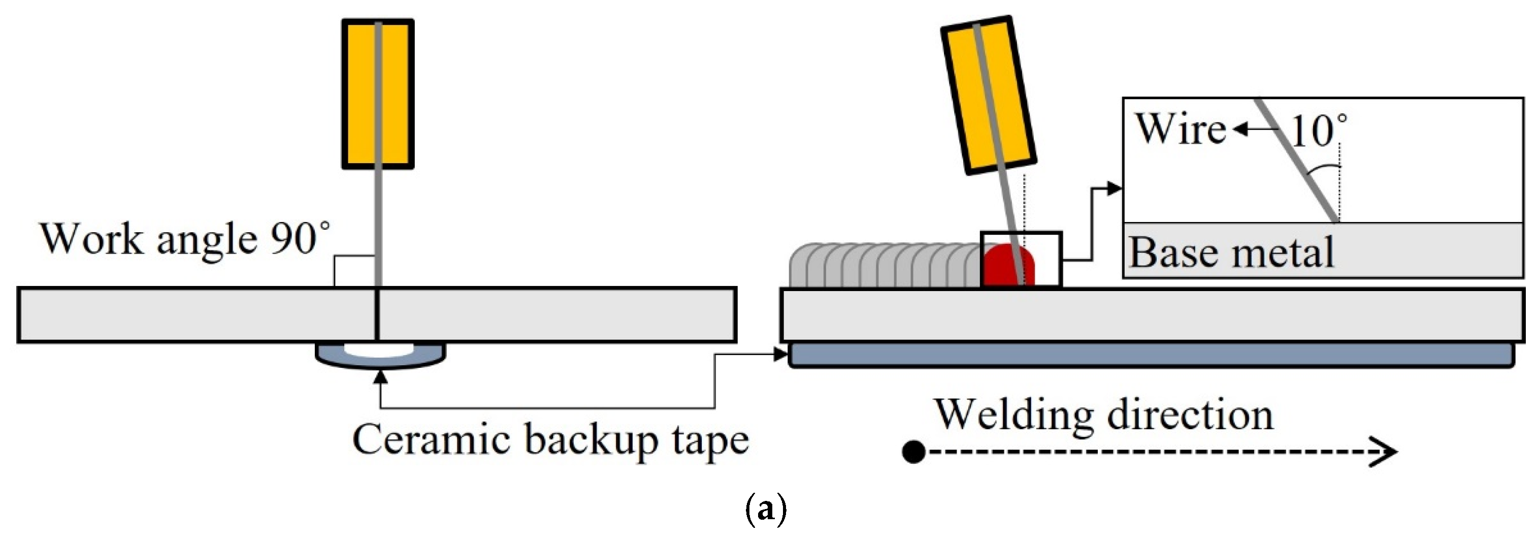
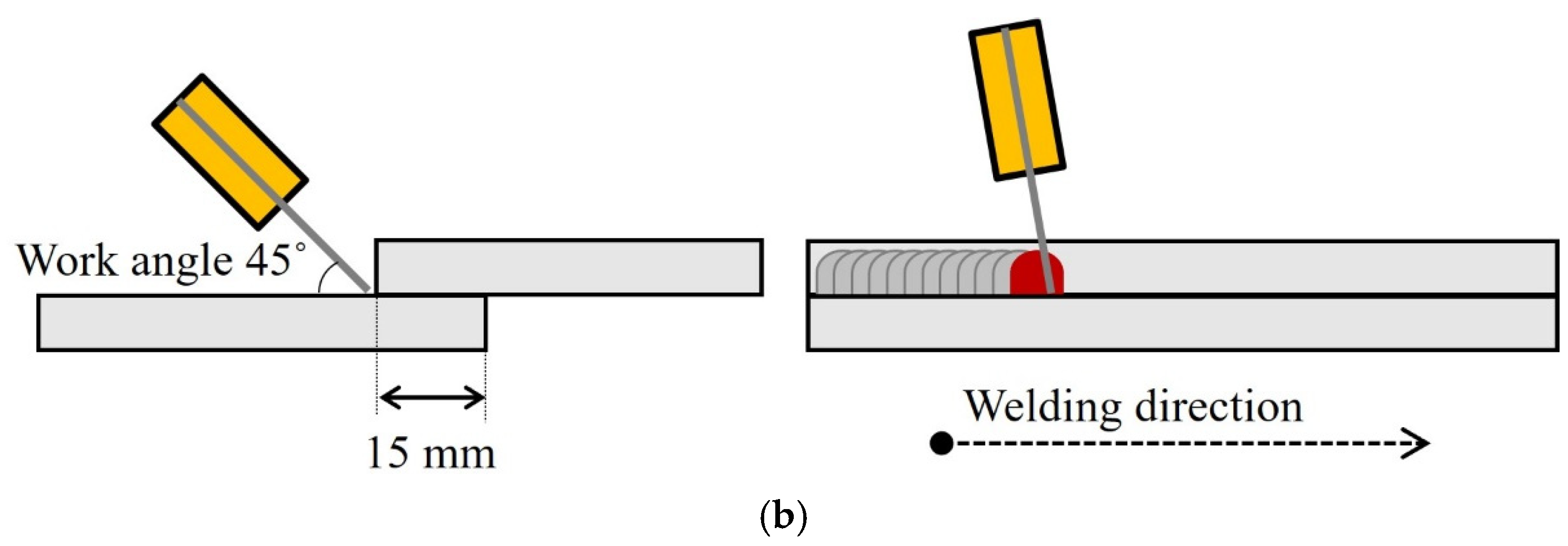
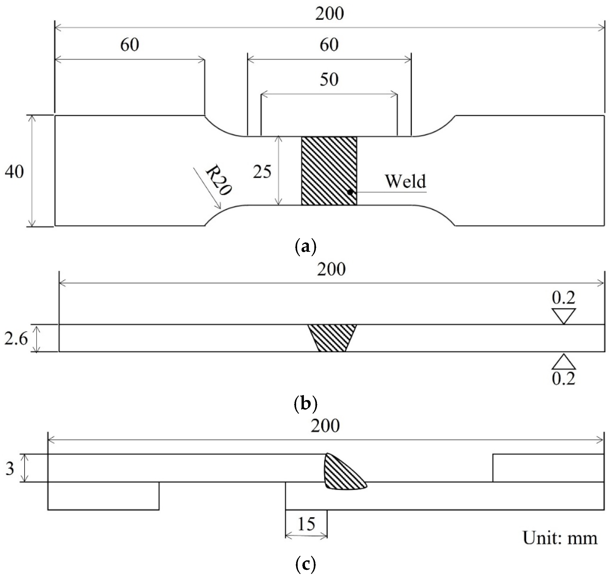
2. Experimental Procedure

The base material was a 3.0 mm thick 5083-O aluminum alloy sheet (Novelis Inc., Atlanta, GA, USA); Table 1 presents its chemical composition. In this study, two types of filler wires with different chemical compositions were prepared to evaluate the mechanical properties of the welded joints. The commercial filler wire AWS A5.10 ER5356 and the filler wire containing Sc and Zr were designated as Al-5.0Mg (1.2 mm) and Al-4.8Mg-0.7Sc-0.3Zr (1.2 mm), respectively. Table 2 lists the chemical compositions of the filler wires.
The base material was cut into pieces of dimensions of 150 mm × 150 mm. The joints were configured in both butt and lap forms (Figure 1); the lap joint overlapped by 15 mm. Welbee W350 (Daihen Co., Osaka, Japan) was used as the welding power source, and a direct current (DC) pulse was applied as the current waveform. During welding, the WFR was increased from 5.0 to 9.0 m/min in increments of 1.0 m/min. The work angle was set to 90° for the butt joint and 45° for the lap joint during welding. An increase in the WFR during butt welding can increase the heat input, potentially leading to welding defects such as burn-through. Therefore, ceramic backup tape was inserted into the back of the joint to prevent the occurrence of this defect. The welding speed (WS) was set to 40 cm/min with a travel angle of 10° in the push direction, and the contact tip-to-work distance (CTWD) was maintained at 15 mm. A shielding gas of 100% Ar was supplied, maintaining a flow rate of 20 L/min during welding. Table 3 lists the welding conditions. The welded joints fabricated using the Al-5.0Mg and Al-4.8Mg-0.7Sc-0.3Zr wires were labeled Al-5.0Mg and Al-4.8Mg-0.7Sc-0.3Zr, respectively.
Tensile test specimens were prepared from the welded specimens according to the ISO 6892 standard [31] (Figure 2a) to evaluate the mechanical properties of the weld joint. For butt welds, the tensile test specimens were manufactured by milling the upper and lower plates by 0.2 mm to minimize the shape effect of the welds (Figure 2b). For lap welds, a spacer with a thickness equal to that of the base material was inserted to minimize the rotation of the specimen before the tensile test (Figure 2c). A universal testing machine (Shimadzu, Kyoto, Japan) with a maximum load of 294 kN was used, and tensile tests were conducted at a tensile speed of 2.0 mm/min. The tensile tests were repeated five times under the same conditions.
The Vickers hardness profile of the weld was measured from a cross-section. One hundred points were measured at 0.3 mm in the depth direction from the top surface, including the weld zone and HAZ. The load, indent spacing, and holding time were 1.96 N, 0.2 mm, and 10 s, respectively.
We conducted a microstructural analysis of the welded joints. Scanning electron microscopy (SEM; FEI, Nova NanoSEM 450, Zeiss, Merlin, Oberkochen, Germany) was performed using an electron backscatter diffractometer (EBSD; Oxford Instruments, Nordlys Nano, Abingdon, UK). The EBSD samples were electropolished using a mixed solution of 90% glacial acetic acid and 10% perchloric acid after mechanical polishing. The high- and low-angle grain boundaries were set to 15° and 3° for grain identification, respectively.

3. Results

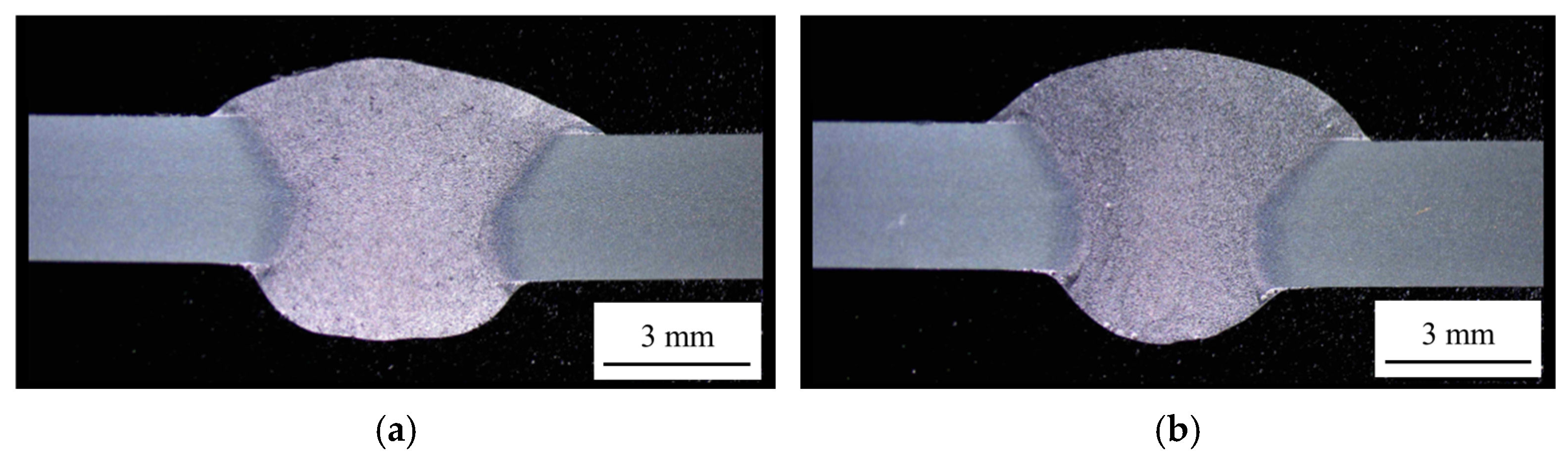
3.1. Evaluation of Welding Characteristics of Butt Welds with Different Wires

During the welding process in the butt joints, the WS was maintained at 40 cm/min, whereas the WFR was increased from 5.0 to 9.0 m/min. Figure 3 illustrates the weld cross-section achieved using the two selected wires at the lowest WFR. We confirmed that complete penetration was achieved under the lowest identified WFR conditions. When Al-4.8Mg-0.7Sc-0.3Zr was used, the weld centerline in the thickness direction was narrower than that observed in the case of Al-5.0Mg. This difference was attributed to variations in the alloying elements and their quantities in Al-4.8Mg-0.7Sc-0.3Zr and Al-5.0Mg, which affected the arc concentration and molten pool behavior. This change in the molten pool behavior indicated that the dilution rate of the welded joint also changed. Despite an increase in the WFR, the addition of ceramic backup tape to the rear side of the joint prevented the occurrence of welding defects such as burn-through.
Figure 4 depicts a comparison of the tensile strengths of the butt joints for different wires based on the changes in the WFR. To eliminate the influence of the weld bead geometry during tensile testing, the upper and lower surfaces of the test specimens were subjected to milling to process the weld beads. Al-4.8Mg-0.7Sc-0.3Zr demonstrated a higher tensile strength than Al-5.0Mg at the same WFR. However, as the WFR increased, a clear trend was observed. The tensile strength of Al-4.8Mg-0.7Sc-0.3Zr decreased from 305 to 269 MPa as the WFR increased from 5.0 to 9.0 m/min. Similarly, in the case of Al-5.0Mg, the tensile strength decreased from 293 to 256 MPa as the WFR increased from 5.0 to 9.0 m/min. This trend confirmed that the tensile strength decreases proportional to the increase in the WFR, and fracture occurs in the fusion zone (FZ) under all WFR conditions.
As indicated in Figure 4, the weld joint of Al-4.8Mg-0.7Sc-0.3Zr exhibited a higher tensile strength than that of Al-5.0Mg at all WFRs. Hardness tests were performed at a WFR of 5.0 m/min, where the tensile strength was the highest; the corresponding results are presented in Figure 5. Measurements were obtained from the center of the FZ to the base metal (BM) at 0.2 mm intervals for a total distance of 10.0 mm. For the welded joints prepared using both wires, the hardness of the FZ was lower than those of the HAZ and BM. The lowest hardness in the FZ was likely the reason for the fracture observed in the FZ during tensile testing. The average hardness in the FZ of Al-4.8Mg-0.7Sc-0.3Zr was 84 HV, which was higher than the average hardness of 77 HV in the FZ of Al-5.0 Mg; this explained the higher tensile strength of Al-4.8Mg-0.7Sc-0.3Zr. Additionally, no significant reduction in hardness was observed due to thermal softening in the HAZ.
During the tensile tests of welds using both wires, a fracture occurred at the center of the FZ, indicating that it was the weakest area. Figure 6 shows the microstructural observations at the center of the FZ in the welds according to the changes in the WFR for both wires. As the WFR of Al-5.0Mg increased, the heat input increased from 1.8 kJ/cm (Figure 6a) to 4.1 kJ/cm (Figure 6c), resulting in a noticeable coarsening of the microstructure. As the heat input increased, the cooling rate after welding decreased, which led to larger grain sizes, more distinct grain boundaries, and a transition from a fine dendritic structure to a coarser structure. In the case of Al-4.8Mg-0.7Sc-0.3Zr (Figure 6d–f), the heat input increased with the increase in WFR, counteracting the grain refinement effect of the Sc and Zr alloys [29,30] and leading to an overall increase in the size of the grains and dendrites. However, the addition of Sc and Zr resulted in a finer grain structure and a more uniform grain distribution than those observed in Al-5.0Mg. The alloys containing Sc and Zr exhibited finer grains than those without Sc and Zr at similar heat input levels. Only the overall microstructure at the center of the FZ was observed (Figure 6), and the degree of grain refinement could not be quantified. Figure 7 depicts the detailed grain structures and sizes obtained using EBSD. In the case of Al-5.0Mg (Figure 7a), large grains were observed at the center of the FZ, whereas smaller grain sizes were observed near the HAZ. During the cooling process after welding, the center of the FZ solidified last, resulting in the largest grain growth owing to the sustained high temperature and prolonged solidification time. In contrast, Al-4.8Mg-0.7Sc-0.3Zr (Figure 7b) exhibited a smaller and more uniform grain structure than Al-5.0Mg. This was attributed to the effect of the Sc and Zr alloys, which inhibited grain coarsening.
Table 4 summarizes the results of the grain size measurements at the FZ center (white square box in Figure 7) according to the WFR. As the WFR increased, the heat input also increased, and the grain size in both wires tended to increase. However, the FZ of Al-4.8Mg-0.7Sc-0.3Zr exhibited a smaller grain size than that of Al-5.0Mg due to the grain coarsening inhibition effect of the Sc and Zr alloys. At a WFR of 5.0 m/min (heat input 1.8 kJ/cm), the grain size of Al-4.8Mg-0.7Sc-0.3Zr was 14.0 µm, which was approximately 18% of the grain size of Al-5.0Mg (75.9 µm).
The supplied wire and base material fused through a phenomenon known as dilution. The dilution rate represents the extent of mixing [32]. Table 5 lists the dilution rate results according to the changes in the WFR. As the WFR increased, the dilution rate increased from 52% to 67% for Al-5.0Mg and from 47% to 63% for Al-4.8Mg-0.7Sc-0.3Zr. We observed that Al-4.8Mg-0.7Sc-0.3Zr exhibited a relatively lower dilution rate than Al-5.0Mg at the same WFR. Typically, a lower dilution rate facilitates a more pronounced effect of the strengthening mechanisms from alloying elements, such as Sc and Zr, that were added to the welding wire. The lower dilution rate is likely because of the addition of various alloying elements, such as Sc, Zr, and Ti, to Al-4.8Mg-0.7Sc-0.3Zr. These elements alter the surface tension, thereby changing the behavior of the molten pool and resulting in a lower dilution rate compared to Al-5.0Mg [33].

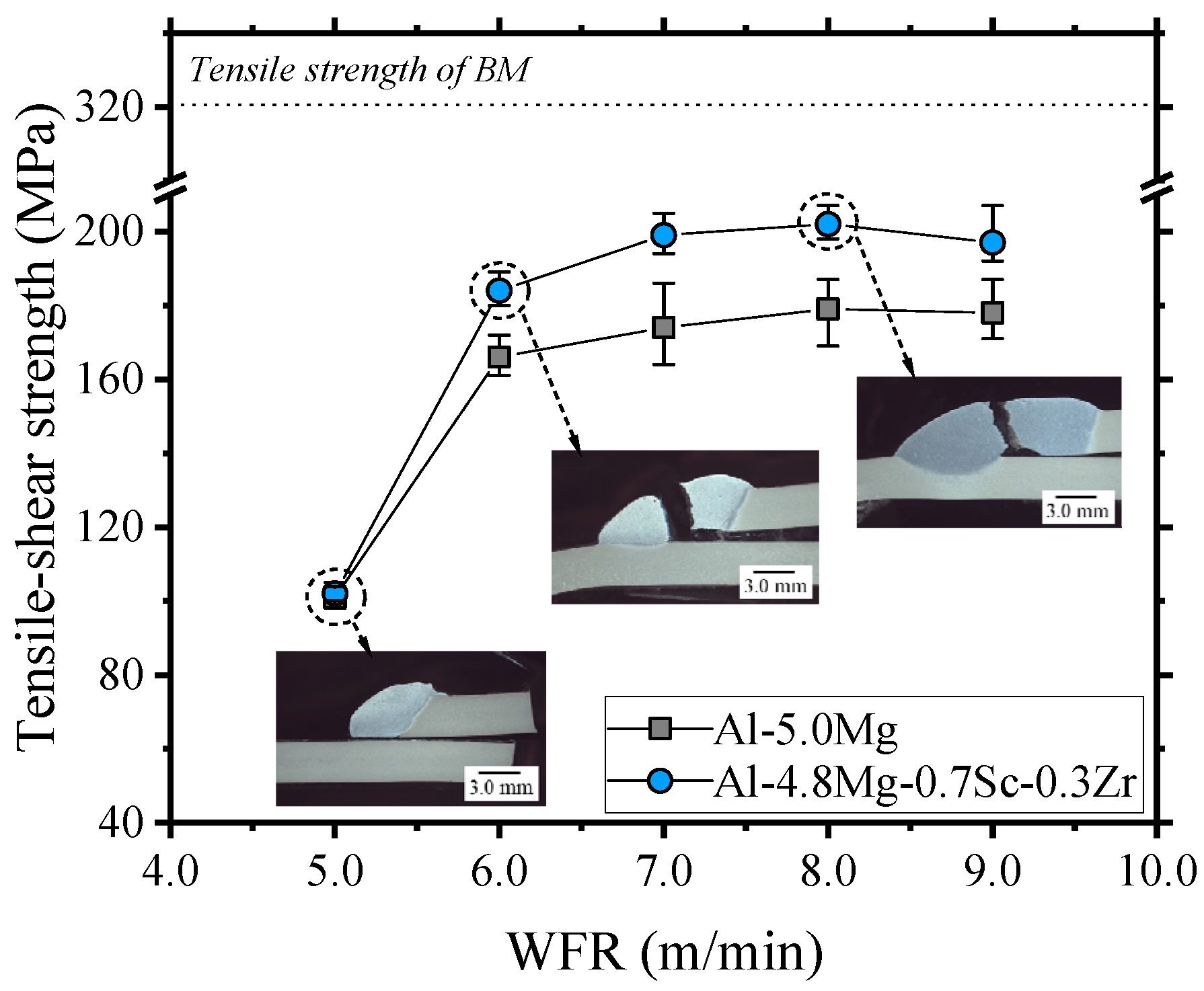
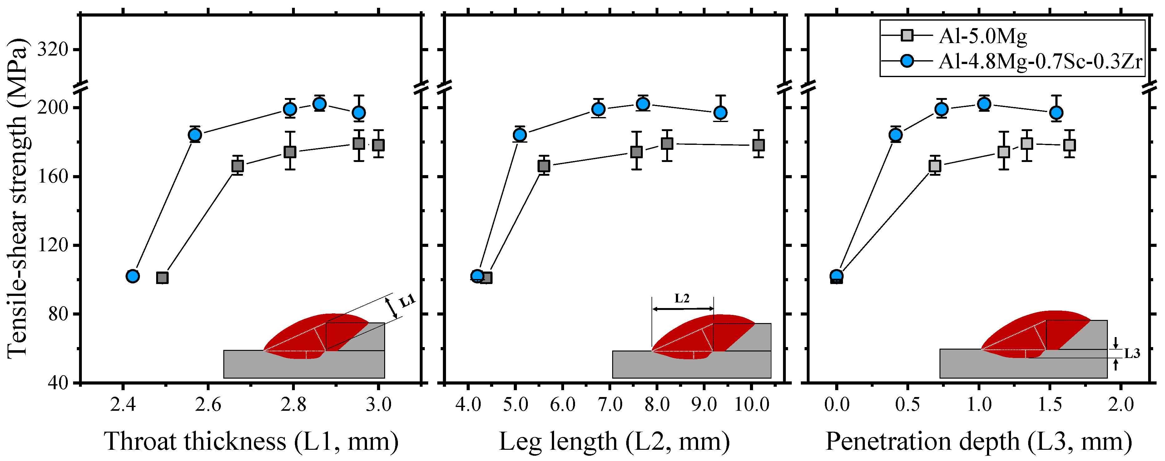
3.2. Evaluation of Welding Characteristics of Lap Welds with Different Wires

Welding was performed by varying the WFR of each wire in the lap joints. Figure 8 illustrates the cross-sectional shape of the weld after welding. The black dotted lines represent the schematic of the overlapping configuration of the lap joint before welding. As the WFR increased, the amount of metal deposited increased, thereby increasing the size of the FZ. At the lowest WFR of 5.0 m/min, the bottom plate and FZ exhibited cold welds with no dilution. Additionally, microporous defects were observed, confirming that the weld shape was suboptimal. This occurred in the lap joint because of the insufficient supply of consumable wires, which prevented the formation of sound welds. At WFRs of 6.0 m/min and higher, no defects such as overlap, microporosity, or root defects were detected in the case of both wires as a sound weld was achieved. Al-5.0Mg exhibited a relatively wider and smoother weld shape than Al-4.8Mg-0.7Sc-0.3Zr. The addition of Si alloying elements to Al-5.0Mg increased the fluidity in the weld pool and improved the wettability of the molten pool, resulting in a broader and smoother bead [34].
Figure 9 depicts the results of the tensile-shear strength of the weld when the WFR is varied for different wires. At a WFR of 5.0 m/min, where imperfect welds occurred, the tensile-shear strengths were nearly identical for Al-5.0Mg (101 MPa) and Al-4.8Mg-0.7Sc-0.3Zr (102 MPa). The tensile-shear strength increased as the WFR increased. At WFRs of 6.0 m/min and higher, Al-4.8Mg-0.7Sc-0.3Zr exhibited an average tensile-shear strength that was 21 MPa higher than that of Al-5.0Mg. At WFRs of 7.0 m/min and higher, Al-5.0Mg and Al-4.8Mg-0.7Sc-0.3Zr reached a saturation point with average tensile-shear strengths of 177 and 199 MPa, respectively. After the tensile test, both wires fractured in the FZ. At a WFR of 5.0 m/min, fractures occurred in the form of separation between the FZ and BM at the interface on the bottom plate due to insufficient penetration and the influence of the small weld size. The generation of cracks was initiated at the weld root, and the cracks propagated through the weld throat to the FZ surface at WFRs of 6.0 m/min and higher.
The weld geometry, including throat thickness (L1), leg length (L2), and penetration depth (L3), is closely associated with the tensile-shear strength of lap welds [35]. The weld sizes L1, L2, and L3 were measured based on variations in the WFR, and their relationship with the tensile-shear strength of the weld was analyzed (Figure 10). Under the same WFR conditions, excluding a WFR of 5.0 m/min where cold welding occurred, the Si-containing Al-5.0Mg exhibited relatively better wettability, resulting in a larger L2 compared with that of Al-4.8Mg-0.7Sc-0.3Zr; this led to an increase in L1. L3 was larger in Al-5.0Mg than in Al-4.8Mg-0.7Sc-0.3Zr. Al-5.0Mg exhibited larger weld dimensions in sound welds, which affected the tensile-shear strength more than it did in Al-4.8Mg-0.7Sc-0.3Zr; however, the tensile strength of the weld was higher in Al-4.8Mg-0.7Sc than in Al-5.0Mg. The addition of Sc and Zr to Al-4.8Mg-0.7Sc-0.3Zr refined the microstructure of the FZ, enhancing the mechanical properties of the weld compared to Al-5.0Mg. In the lap joints, increased weld geometry dimensions enhanced the resistance to shear forces, thereby improving the tensile-shear strength. After achieving a certain level of weld geometry size (Al-5.0Mg: L1 = 2.8 mm, L2 = 7.6 mm, L3 = 1.2 mm; Al-4.8Mg-0.7Sc-0.3Zr: L1 = 2.8 mm, L2 = 6.8 mm, L3 = 0.7 mm), the tensile-shear strength reached saturation, averaging at 177 and 199 MPa for Al-5.0Mg and Al-4.8Mg-0.7Sc-0.3Zr, respectively.
Figure 11 presents a comparison of the hardness of the FZ measured at various WFR values for each wire. The average hardness of the FZ in the case of Al-4.8Mg-0.7Sc-0.3Zr was higher than that of Al-5.0Mg under all WFR conditions. As the WFR increased, the average hardness of the FZ decreased. The alloying elements Sc and Zr in Al-4.8Mg-0.7Sc-0.3Zr inhibited grain coarsening, resulting in a higher hardness of the FZ compared with that of Al-5.0Mg. Additionally, as the WFR increased, the heat input increased, leading to a decrease in the cooling rate. Furthermore, the increased dilution with the BM reduced the hardness of the FZ.

4. Discussion

Figure 12 illustrates the welded joint efficiency of the butt and lap joints when Al-5.0Mg and Al-4.8Mg-0.7Sc-0.3Zr wires were used. In the butt joints, the weld joint efficiency of Al-4.8Mg-0.7Sc-0.3Zr was higher than that of Al-5.0Mg. The alloy design of the butt joints provides profound insights into the microstructural transformations and their subsequent impact on the mechanical properties of the overall weld regions. As depicted in Figure 7, the EBSD images delineate the disparities in the grain structure between the welds fabricated using the Al-5.0Mg and Al-4.8Mg-0.7Sc-0.3Zr filler wires. The welds fabricated using the Al-4.8Mg-0.7Sc-0.3Zr filler wire exhibited a significantly finer and more uniform grain structure in the FZ and HAZ than those fabricated using the Al-5.0Mg filler wire. This pronounced grain refinement was predominantly due to the presence of the alloying elements Sc and Zr in the filler wire. During solidification, these elements precipitate as stable Al3Sc and Al3Zr compounds, which serve as potent heterogeneous nucleation sites for α-Al grains. This impedes the growth of dendritic structures and fosters the formation of equiaxed grains [36,37,38,39]. The reduction in grain size due to Sc and Zr can be explained based on two primary mechanisms.
First, Al3Sc and Al3Zr precipitates have been reported to significantly increase the nucleation rate owing to the effect of nucleation enhancement caused by the presence of numerous nucleation sites during solidification, thereby resulting in an increased grain density [36]. Second, these precipitates act as barriers to grain boundary migration, effectively restricting grain coarsening during the thermal cycles occurring in the welding process [37]. Ying Deng et al. [38] reported that the strength increases caused by the addition of Sc and Zr were primarily derived from the refining strengthening of primary Al3(Sc, Zr) particles formed during solidification, substructure strengthening, and Orowan strengthening caused by the secondary Al3(Sc, Zr) particles formed during the homogenization treatment. Among these, the Orowan strengthening of secondary Al3(Sc, Zr) particles was determined to be the most important strengthening mechanism of Sc and Zr microalloying in aged Al–Zn–Mg alloys [38]. These mechanisms synergistically contributed to the refined grain structure observed in the EBSD images, where the grains in the FZ of the Al-4.8Mg-0.7Sc-0.3Zr welds were smaller and more uniformly distributed than those in the Al-5.0Mg welds.
The refined grain structure exhibited by the Al-4.8Mg-0.7Sc-0.3Zr welds exerted a substantial influence on the mechanical properties of the FZ. Finer grains enhance the yield strength and hardness according to the Hall–Petch relationship, wherein the increased area of the grain boundaries acts as a formidable obstacle to dislocation motion [36]. This results in a stronger and harder weld metal, which is imperative for sustaining the structural integrity of the joint under mechanical stress.
The EBSD analysis revealed a discernible variation in the grain boundary character distribution between the two filler wires. The Al-4.8Mg-0.7Sc-0.3Zr welds exhibited a higher proportion of low-angle sub-grain boundaries, which are typically associated with improved toughness and ductility. In contrast, the Al-5.0Mg welds demonstrated a higher proportion of high-angle coarsened grain boundaries, which were more susceptible to crack initiation and propagation.
The HAZ is a critical region in welded joints, where the microstructure and properties of the BM undergo significant alterations owing to thermal cycling. The EBSD data indicated that the grain size in the HAZ was generally larger than that in the FZ, particularly in the Al-5.0Mg welds. This grain coarsening within the HAZ was primarily attributed to the heat input during welding, which promoted grain growth in the absence of sufficient nucleation sites. However, in the Al-4.8Mg-0.7Sc-0.3Zr welds, the presence of Sc and Zr mitigated this grain growth. The precipitates formed by these alloying elements during welding stabilized the grain structure, thereby reducing the extent of grain coarsening within the HAZ. This stabilization resulted in a more consistent and refined grain structure across both the weld zone and HAZ, which in turn enhanced the mechanical properties by increasing the resistance to crack propagation and improving the overall toughness of the joint [37,39].
Finally, the misorientation analysis based on the EBSD provided a better understanding of the deformation mechanisms within the welded joint. The Al-4.8Mg-0.7Sc-0.3Zr welds displayed a higher density of sub-grain structures and a more uniform distribution of misorientation angles. This uniformity suggested that the weld metal underwent a more consistent plastic deformation, which was advantageous for the even distribution of stress and the prevention of localized failure. Conversely, the Al-5.0Mg welds exhibited a more heterogeneous distribution of misorientations, indicating localized strain accumulation that could potentially lead to premature failure.
As the deposition rate of the filler wire increased, the heat input also increased, leading to the coarsening of the microstructure in the FZ. This in turn reduced the tensile strength of the butt joints. Conversely, in the case of lap joints, the weld tensile-shear strength increased with a higher WFR, exhibiting a trend opposite to that of the butt joints (Figure 12). The mechanical properties of lap joints rely on the weld geometry, and achieving a sufficiently large weld size requires the use of a filler wire; in other words, an adequate deposition rate is necessary. Typically, an increase in the deposition rate leads to a higher heat input, which results in the coarsening of the microstructure and weakens the mechanical properties of the weld. However, in lap joints, the tensile-shear strength is more significantly influenced by the weld geometry than by the microstructure.

5. Conclusions

In this study, we investigated the welding performance and microstructural characteristics of Al-5.0Mg and Al-4.8Mg-0.7Sc-0.3Zr filler wires in the MIG welding of butt and lap joints.
The key findings can be summarized as follows:
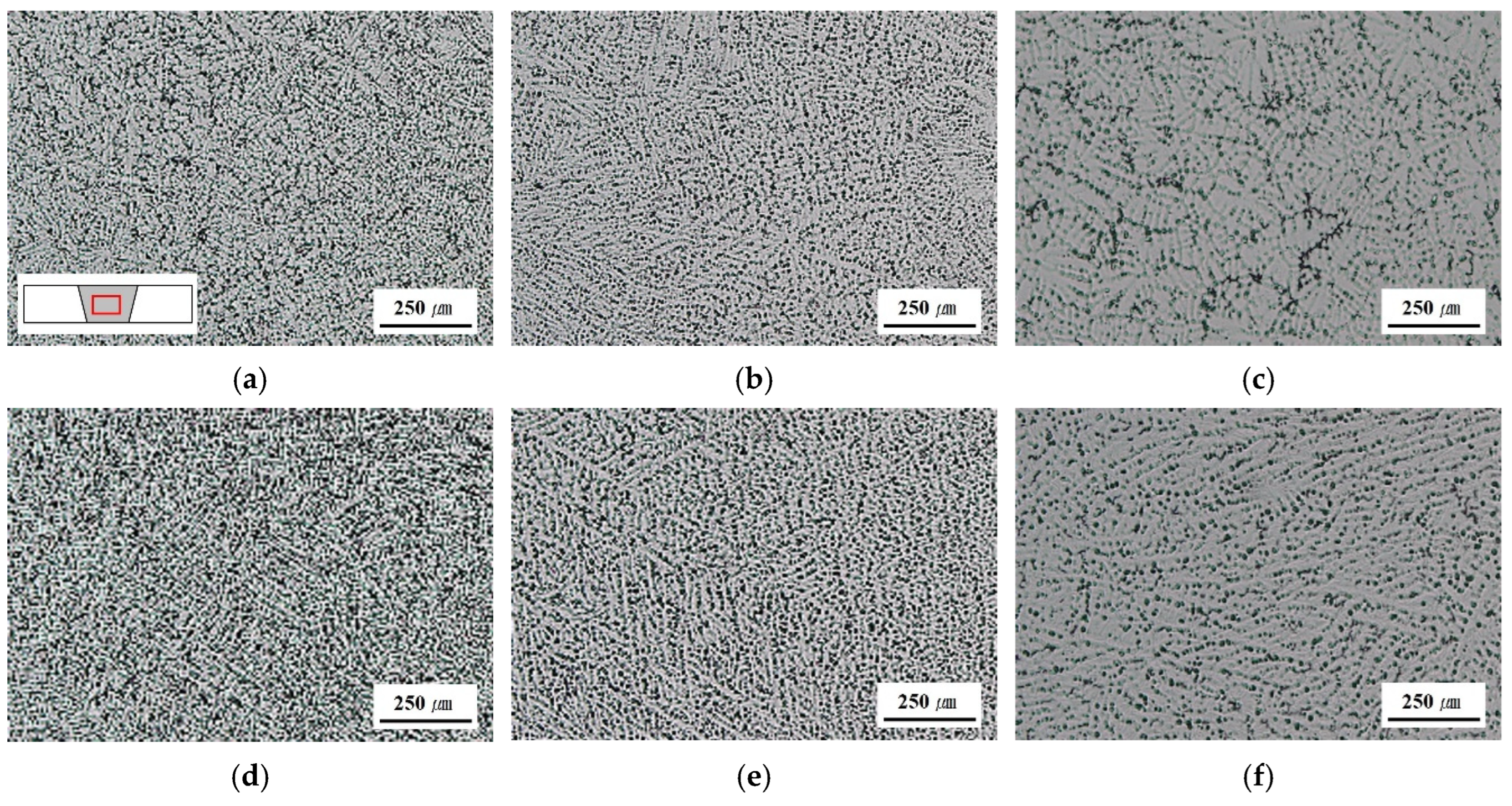
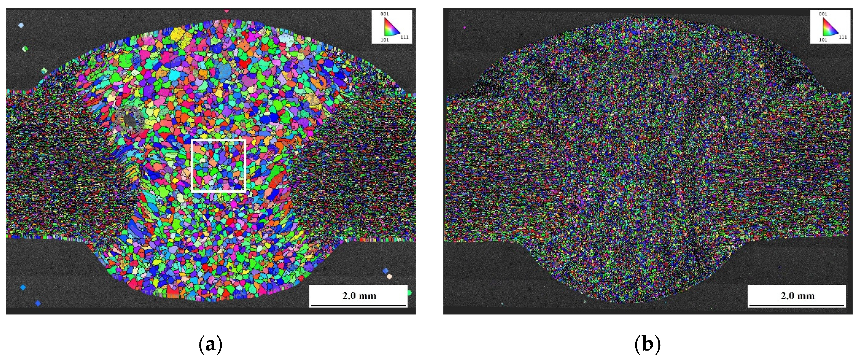
  • The addition of Sc and Zr to Al-4.8Mg-0.7Sc-0.3Zr significantly refined the grain structure in the FZ compared with Al-5.0Mg. The Al3Sc and Al3Zr precipitates acted as potent nucleation sites and impeded grain growth during solidification, resulting in a finer and more uniform grain structure.
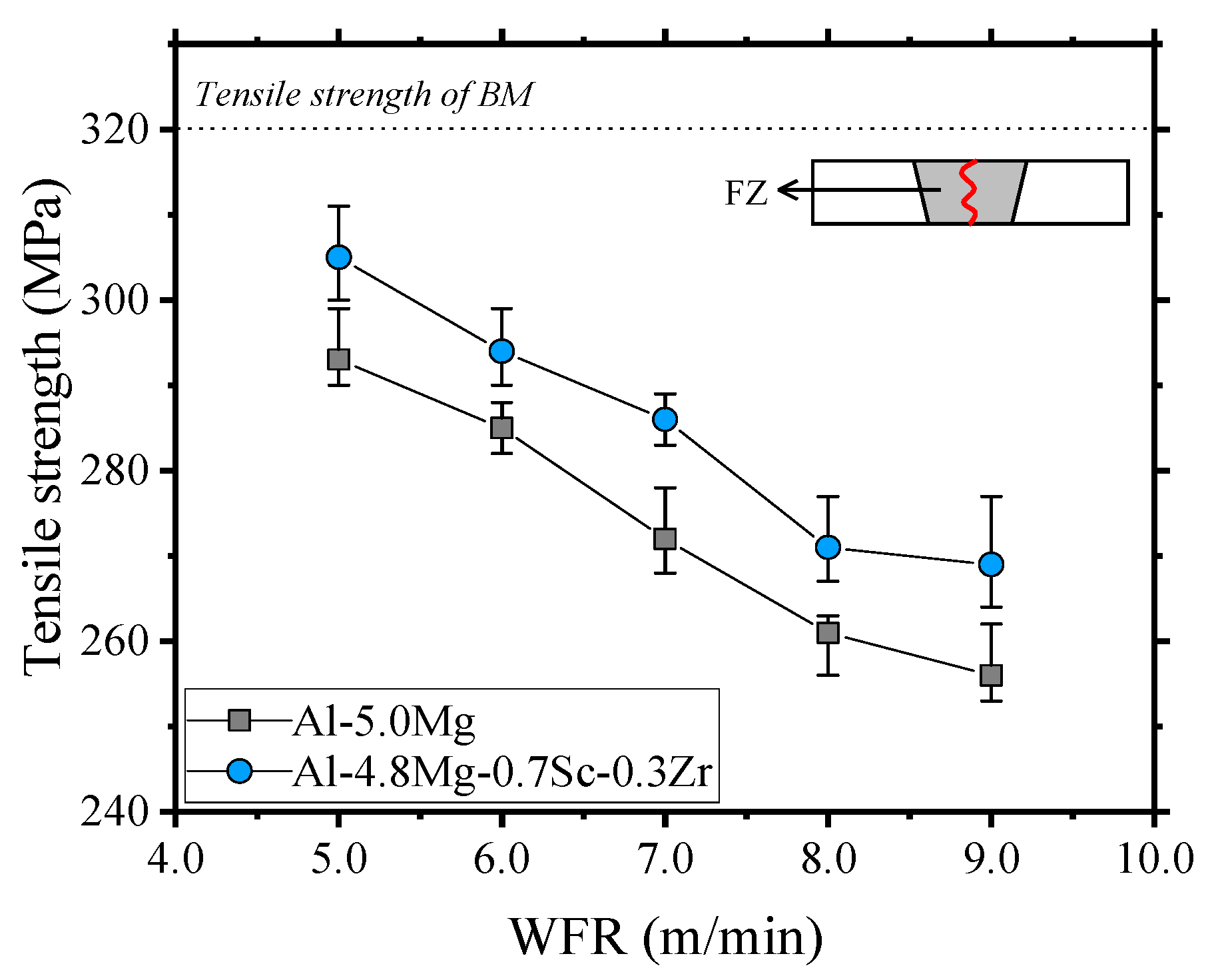
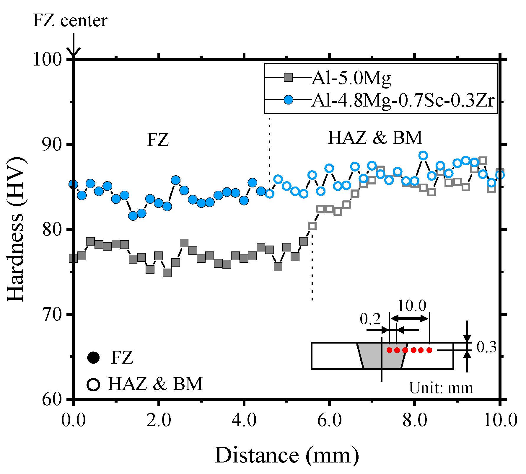
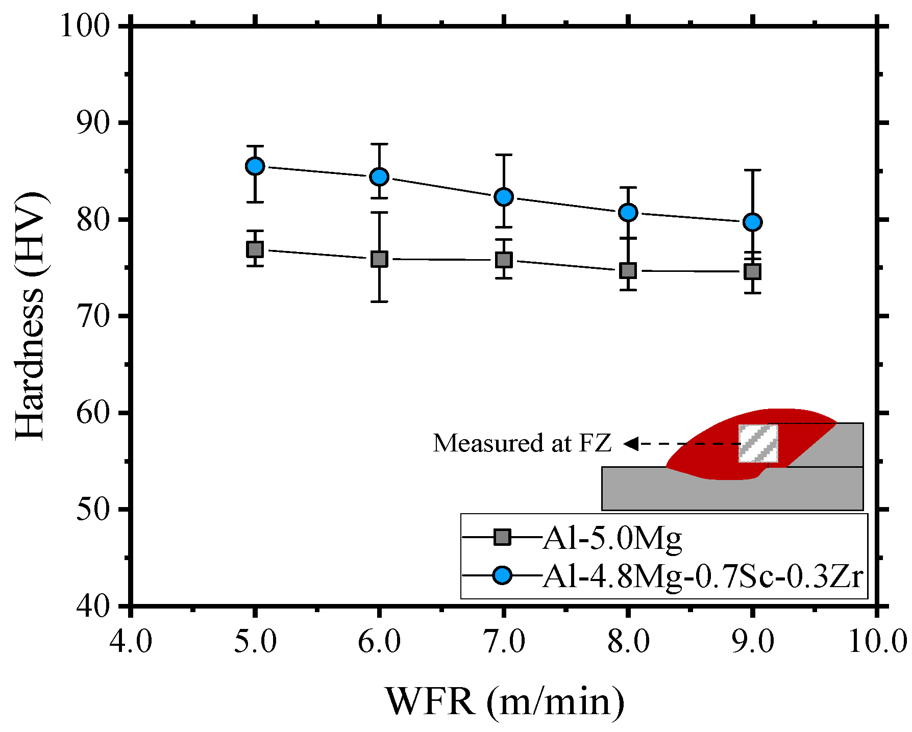
  • The Al-4.8Mg-0.7Sc-0.3Zr filler consistently exhibited higher tensile strength and hardness in the FZ under all WFR conditions. This enhancement was attributed to the refined microstructure and strengthening effects induced by Sc and Zr, which contributed to the superior mechanical performance of Al-4.8Mg-0.7Sc-0.3Zr over Al-5.0Mg.
  • The welded joint efficiency of Al-4.8Mg-0.7Sc-0.3Zr was superior to that of Al-5.0Mg in both the butt and lap joints, with notable improvements in the butt joints. The fine and stable microstructures in Al-4.8Mg-0.7Sc-0.3Zr ensured enhanced structural integrity, which improved the joint efficiency.
  • Increasing the WFR resulted in a higher heat input, which led to microstructural coarsening in the FZ. This in turn reduced the tensile strength of the butt joints. However, the tensile-shear strength in the lap joints increased with the WFR, suggesting that the weld geometry influenced the joint strength more than the microstructural features in the lap configurations.
  • A saturation point in the tensile-shear strength was observed in both filler alloys after attaining a specific weld geometry size. Al-5.0Mg and Al-4.8Mg-0.7Sc-0.3Zr reached average tensile-shear strengths of 177 and 199 MPa, respectively, indicating that the maximum mechanical performance was achieved at the optimal geometry size for each alloy.
  • These findings underscore the beneficial effects of Sc and Zr alloying in Al-4.8Mg-0.7Sc-0.3Zr on weld joint performance, particularly in enhancing microstructural stability and mechanical strength. This implies that Sc and Zr could serve as promising filler materials for high-performance welding applications. Furthermore, the study findings provide valuable insights for optimizing the filler wire compositions and welding parameters in aluminum alloys.

Author Contributions

Conceptualization, D.-Y.K. and J.Y.; methodology, D.-Y.K. and H.K.; software, H.K. and H.-J.K.; validation, D.-Y.K. and J.Y.; formal analysis, D.-Y.K. and H.-J.K.; investigation, H.K. and H.-J.K.; resources, D.-Y.K. and J.Y.; data curation, H.K., D.-Y.K., and H.-J.K.; writing—original draft preparation, H.K. and D.-Y.K.; writing—review and editing, H.-J.K. and J.Y.; visualization, H.K., D.-Y.K. and H.-J.K.; supervision, D.-Y.K. and J.Y.; project administration, J.Y.; funding acquisition, J.Y. All authors have read and agreed to the published version of the manuscript.

Funding

This research was supported by the 2024 Ministry of Trade, Industry, and Energy and the Korea Planning and Evaluation Institute of Industrial Technology (KEIT) grant funding (Development of Intelligent Process Models and Applied Advanced Robots For Metals Plastics, Electronics, Semiconductors, and Bio, RS-2024-00418239, Ministry of Trade, Industry and Energy).

Data Availability Statement

The original contributions presented in the study are included in the article; further inquiries can be directed to the corresponding author.

Conflicts of Interest

Author Hye-Jin Kim was employed by the Hyundai-Steel Company. The remaining authors declare that the research was conducted in the absence of any commercial or financial relationships that could be construed as a potential conflict of interest.

References

  1. Benedyk, J.C. Aluminum Alloys for Lightweight Automotive Structures. In Materials, Design and Manufacturing for Lightweight Vehicles; Mallick, P.K., Ed.; Woodhead Publishing: Cambridge, UK, 2010; pp. 79–113. [Google Scholar]
  2. Musfirah, A.H.; Jaharah, A.G. Magnesium and aluminum alloys in automotive industry. J. Appl. Sci. Res. 2012, 8, 4865–4875. [Google Scholar]
  3. Miller, W.S.; Zhuang, L.; Bottema, J.; Wittebrood, A.; De Smet, P.; Haszler, A.; Vieregge, A.J.M.S. Recent development in aluminium alloys for the automotive industry. Mater. Sci. Eng. A 2000, 280, 37–49. [Google Scholar] [CrossRef]
  4. Ardika, R.D.; Triyono, T.; Muhayat, N. A review porosity in aluminum welding. Procedia Struct. Integr. 2021, 33, 171–180. [Google Scholar] [CrossRef]
  5. Rudy, J.F.; Rupert, E.J. Effects of porosity on mechanical properties of aluminum welds. Weld. J. 1970, 49, 322. [Google Scholar]
  6. Chen, Q.; Ge, H.; Yang, C.; Lin, S.; Fan, C. Study on pores in ultrasonic-assisted TIG weld of aluminum alloy. Metals 2017, 7, 53. [Google Scholar] [CrossRef]
  7. Miao, Y.; Wang, Z.; Liu, J.; Zhao, Y.; Wu, Y.; Li, C. Bypass-current plasma arc welding of aluminum alloy: Thermal behavior, residual stress, and distortion. Int. J. Adv. Manuf. Technol. 2022, 119, 5365–5376. [Google Scholar] [CrossRef]
  8. Chen, B.Q.; Liu, K.; Xu, S. Recent Advances in Aluminum Welding for Marine Structures. J. Mar. Sci. Eng. 2024, 12, 1539. [Google Scholar] [CrossRef]
  9. Liu, J.; Li, Z.; Liu, T.; Li, L.; Liu, C.; Yang, L. A novel compliant assembly variation analysis with consideration of initial deviation and welding shrinkage. Ocean Eng. 2021, 237, 109636. [Google Scholar] [CrossRef]
  10. Kim, D.Y.; Hwang, I.; Jeong, G.; Kang, M.; Kim, D.; Seo, J.; Kim, Y.M. Effect of porosity on the fatigue behavior of gas metal arc welding lap fillet joint in GA 590 MPa steel sheets. Metals 2018, 8, 241. [Google Scholar] [CrossRef]
  11. Chen, S.; Chi, Y.; Zhang, P.; Shi, Y. Mechanism to reduce the porosity during argon arc welding of aluminum alloys by changing the arc angle. Metals 2020, 10, 1121. [Google Scholar] [CrossRef]
  12. Huang, L.; Hua, X.; Wu, D.; Jiang, Z.; Li, F.; Wang, H.; Shi, S. Microstructural characterization of 5083 aluminum alloy thick plates welded with GMAW and twin wire GMAW processes. Int. J. Adv. Manuf. Technol. 2017, 93, 1809–1817. [Google Scholar] [CrossRef]
  13. Chen, C.; Sun, G.; Du, W.; Li, Y.; Fan, C.; Zhang, H. Influence of heat input on the appearance, microstructure and microhardness of pulsed gas metal arc welded Al alloy weldment. J. Mater. Res. Technol. 2022, 21, 121–130. [Google Scholar] [CrossRef]
  14. Furukawa, K. New CMT arc welding process–welding of steel to aluminium dissimilar metals and welding of super-thin aluminium sheets. Weld. Int. 2006, 20, 440–445. [Google Scholar] [CrossRef]
  15. Singh, I.J.; Murtaza, Q.; Kumar, P. Effect of Welding Speed on Metallurgical Characterization of CMT Welding of Dissimilar Aluminium Alloys of AA6061 and AA8011. Silicon 2024, 16, 3891–3903. [Google Scholar] [CrossRef]
  16. Nalajala, D.; Mookara, R.K.; Amirthalingam, M. Analysis of metal transfer characteristics in low-heat input gas metal arc welding of aluminum using aluminum–silicon alloy fillers. Metall. Mater. Trans. B 2022, 53, 2914–2924. [Google Scholar] [CrossRef]
  17. Kumar, R.; Dilthey, U.; Dwivedi, D.K.; Ghosh, P.K. Thin sheet welding of Al 6082 alloy by AC pulse-GMA and AC wave pulse-GMA welding. Mater. Des. 2009, 30, 306–313. [Google Scholar] [CrossRef]
  18. Tong, H.; Ueyama, T.; Harada, S.; Ushio, M. Quality and productivity improvement in aluminium alloy thin sheet welding using alternating current pulsed metal inert gas welding system. Sci. Technol. Weld. Join. 2001, 6, 203–208. [Google Scholar] [CrossRef]
  19. Dutra, J.C.; Silva, R.H.G.E.; Savi, B.M.; Marques, C.; Alarcon, O.E. New methodology for AC-pulsed GMAW parameterization applied to aluminum shipbuilding. J. Braz. Soc. Mech. Sci. Eng. 2016, 38, 99–107. [Google Scholar] [CrossRef]
  20. Lee, B.H.; Kim, S.H.; Park, J.H.; Kim, H.W.; Lee, J.C. Role of Mg in simultaneously improving the strength and ductility of Al–Mg alloys. Mater. Sci. Eng. A. 2016, 657, 115–122. [Google Scholar] [CrossRef]
  21. Kang, T.; Yu, J.; Kim, Y.M.; Hwang, I.; Lee, S.H.; Kim, D.Y. Weldability evaluation of GMAW and GTAW for Al-6.7 wt.% Mg alloy. J. Weld. Join. 2021, 39, 471–479. [Google Scholar] [CrossRef]
  22. Kim, G.G.; Kim, D.Y.; Hwang, I.; Kim, D.; Kim, Y.M.; Park, J. Mechanical properties of aluminum 5083 alloy GMA welds with different magnesium and manganese content of filler wires. Appl. Sci. 2021, 11, 11655. [Google Scholar] [CrossRef]
  23. Willey, L.A. Aluminum Scandium Alloy. U.S. Patent No. 3,619,181, 9 November 1971. [Google Scholar]
  24. Lamikhov, L.K.; Samsonov, G.V. Inoculation of aluminum and AL7 alloy with transition metals. Tsvetn. Met. 1964, 8, 79–82. [Google Scholar]
  25. Elagin, V.I. Alloying of Deformable Aluminum Alloys with Transition Metals; Metallurgiya: Moscow, Russia, 1975. (In Russian) [Google Scholar]
  26. Elagin, V.I.; Zakharov, V.V.; Rostova, T.D. Nondendritic structure of ingots from aluminum alloys. In Physical Metallurgy, Casting, and Treatment of Alloys; VILS: Moscow, Russia, 1995; pp. 6–16. (In Russian) [Google Scholar]
  27. Zakharov, V.V. Effect of scandium on the structure and properties of aluminum alloys. Heat Treat. Met. 2003, 45, 246–253. [Google Scholar] [CrossRef]
  28. Filatov, Y.A. Deformable alloys based on the Al-Mg-Se system. Heat Treat. Met. 1996, 38, 271–274. [Google Scholar] [CrossRef]
  29. Su, D.; Zhang, J.; Wang, B. The microstructure and weldability in welded joints for AA 5356 aluminum alloy after adding modified trace amounts of Sc and Zr. J. Manuf. Process. 2020, 57, 488–498. [Google Scholar] [CrossRef]
  30. Huang, X.; Pan, Q.; Li, B.; Liu, Z.; Huang, Z.; Yin, Z. Effect of minor Sc on microstructure and mechanical properties of Al–Zn–Mg–Zr alloy metal–inert gas welds. J. Alloys Compd. 2015, 629, 197–207. [Google Scholar] [CrossRef]
  31. ISO 6892; Metallic Materials—Tensile Testing—Part 1: Method of Test at Room Temperature. International Organization for Standardization: Geneva, Switzerland, 2016; pp. 1–45.
  32. Zhang, Z.; Huang, X.; Yao, P.; Xue, J. A New Method for Weld Dilution Calculation through Chemical Composition Analysis. Metals 2021, 11, 131. [Google Scholar] [CrossRef]
  33. Keene, B.J. A Review of the Surface Tension of Silicon and Its Binary Alloys with Reference to Marangoni Flow. Surf. Interface Anal. 1987, 10, 367–383. [Google Scholar] [CrossRef]
  34. Huang, J.; He, X.; Guo, Y.; Zhang, Z.; Shi, Y.; Fan, D. Joining of Aluminum Alloys to Galvanized Mild Steel by the Pulsed DE-GMAW with the Alternation of Droplet Transfer. J. Manuf. Process. 2017, 25, 16–25. [Google Scholar] [CrossRef]
  35. Kim, D.Y.; Lee, T.H.; Kim, C.; Kang, M.; Park, J. Gas Metal Arc Welding with Undermatched Filler Wire for Hot-Press-Formed Steel of 2.0 GPa Strength: Influence of Filler Wire Strength and Bead Geometry. Mater. Today Commun. 2023, 34, 105244. [Google Scholar] [CrossRef]
  36. Sanders, T.H.; Starke, E.A. Effect of Scandium Additions on the Microstructure and Mechanical Properties of Al-Mg Alloys. J. Mater. Sci. 1995, 30, 1015–1022. [Google Scholar]
  37. Okamoto, H. Scandium-Zirconium (Sc-Zr) Binary Alloy Phase Diagram. J. Phase Equilibria Diffus. 2007, 28, 190–191. [Google Scholar]
  38. Deng, Y.; Yin, Z.; Zhao, K.; Duan, J.; He, Z. Effects of Sc and Zr Microalloying Additions on the Microstructure and Mechanical Properties of New Al–Zn–Mg Alloys. J. Alloys Compd. 2012, 530, 71–80. [Google Scholar] [CrossRef]
  39. Miller, M.K.; Russell, K.F. EBSD Analysis of Precipitates in Al-Sc-Zr Alloys. Mater. Charact. 2006, 57, 205–210. [Google Scholar]
Figure 1. Weld joint preparation: (a) butt joint; (b) lap joint.
Metals 15 00001 g001aMetals 15 00001 g001b
Figure 2. Configuration of the tensile test specimens: (a) top view; (b) side view of the butt weld; (c) side view of the lap weld.
Metals 15 00001 g002
Figure 3. Cross-sectional image of a butt joint weld with a filler wire: (a) Al-5.0Mg wire at a feed rate (WFR) of 5.0 m/min; (b) Al-4.8Mg-0.7Sc-0.3Zr at a WFR of 5.0 m/min.
Metals 15 00001 g003
Figure 4. Relationship between WFR changes and the tensile strength of the butt weld joints.
Metals 15 00001 g004
Figure 5. Hardness of butt-welded joints with each wire (WFR 5.0 m/min).
Metals 15 00001 g005
Figure 6. Microstructural images of butt joints in AA5083 with a filler metal: (a) Al-5.0Mg, WFR = 5.0 m/min; (b) Al-5.0Mg, WFR = 7.0 m/min; (c) Al-5.0Mg, WFR = 9.0 m/min; (d) Al-4.8Mg-0.7Sc-0.3Zr, WFR = 5.0 m/min; (e) Al-4.8Mg-0.7Sc-0.3Zr, WFR = 7.0 m/min; (f) Al-4.8Mg-0.7Sc-0.3Zr, WFR = 9.0 m/min.
Metals 15 00001 g006
Figure 7. Electron backscatter diffractometer (EBSD) images of butt joints in AA5083 with a filler metal (WFR = 5.0 m/min, white box: grain size measurement location): (a) Al-5.0Mg; (b) Al-4.8Mg-0.7Sc-0.3Zr.
Metals 15 00001 g007
Figure 8. Cross-sectional images of the lap weld based on variations in the WFR.
Metals 15 00001 g008
Figure 9. Tensile-shear strength and fracture morphology in the lap weld according to variations in the WFR.
Metals 15 00001 g009
Figure 10. Relationship between the weld size of a lap joint and the tensile-shear strength.
Metals 15 00001 g010
Figure 11. Relationship between the hardness of the fusion zone (FZ) in lap joints and variations in the WFR.
Metals 15 00001 g011
Figure 12. Welded joint efficiency in the butt and lap joints based on variations in the WFR.
Metals 15 00001 g012
Table 1. Chemical composition of the base material (wt.%).
Chemical Composition
Base materialMgSiScZrMnTiAl
AA5083-O4.4580.094--0.6830.012Bal.
Table 2. Chemical composition of the filler wires (wt.%).
Chemical Composition
Filler wireMgSiScZrMnTiAl
Al-5.0Mg4.980.13--0.060.07Bal.
Al-4.8Mg-0.7Sc-0.3Zr4.75-0.700.300.550.15Bal.
Table 3. Welding conditions.
ParameterValue
Weld jointButt jointLap joint
Power sourceWelbee W350
WaveformDC pulse
WFR (m/min)5.06.07.08.09.0
Heat input (kJ/cm)1.822.483.043.564.15
Work angle (°)9045
WS (cm/min)40
Travel angle (°)Push 10
CTWD (mm)15
Shielding gas100% Ar (20 L/min)
Table 4. Comparison of grain size in the weld of a butt joint based on variations in the wire feed rate (WFR).
WFR (m/min)5.06.07.08.09.0
Heat input (kJ/cm)1.822.483.043.564.14
Grain size (µm)Al-5.0Mg75.9201.2241.6305.4346.4
Al-4.8Mg-0.7Sc-0.3Zr14.0133.2177.0251.2274.0
Table 5. Dilution rates according to changes in the WFR.
WFR (m/min)5.06.07.08.09.0
Al-5.0Mg (%)5258626467
Al-4.8Mg-0.7Sc-0.3Zr (%)4752576063
Disclaimer/Publisher’s Note: The statements, opinions and data contained in all publications are solely those of the individual author(s) and contributor(s) and not of MDPI and/or the editor(s). MDPI and/or the editor(s) disclaim responsibility for any injury to people or property resulting from any ideas, methods, instructions or products referred to in the content.

