Abstract
Super-duplex stainless steels (SDSSs) were introduced in the oil and gas industry due to their high resistance to pitting corrosion, promoted by the high content of alloying elements. The welding process can cause an unbalanced ferrite/austenite microstructure and, consequently, the possibility of deleterious phases, increasing the risk of failure. The aim of this work is to investigate the behavior of the heat-affected zone (HAZ) of SDSS UNS S32750 steel produced with different thermal inputs simulated in a Gleeble® welding simulator and correlate these findings with its corrosion properties. The pitting resistance was investigated by electrochemical techniques in sodium chloride solution, and the critical pitting temperature (CPT) was calculated for each evaluated microstructure. The material as received presents 46.19 vol% ferrite and a high corrosion resistance, with a CPT of 71.54 °C. HAZ-simulated cycles resulted in similar ferrite percentages, between 54.09 vol% and 57.25 vol%. A relationship was found between heat input, ferrite content, and CPT: increasing the heat input results in greater ferrite content and lowers the CPT, which may favor the pitting corrosion process. Therefore, it is concluded that the ferrite content directly influences the pitting behavior of the material.
1. Introduction
Duplex stainless steels (DSSs) are alloys with a high concentration of alloying elements that lead to an approximate phase balance of 50% austenite and 50% ferrite [1]. These steels have been recognized since the 1930s and have undergone rapid development since the early 1980s, at which time they were introduced into the oil and gas industry due to their superior pitting corrosion resistance. Throughout their evolution, these steels have been commercially classified into three distinct categories: duplex, super-duplex, and hyper-duplex; each of these encompasses an austenite–ferrite microstructure, with progressively higher alloy content [2,3,4].
Fundamentally, the discriminating factor among them lies in the value of the pitting resistance equivalent number (PREN), which serves as a metric for evaluating their resistance to pitting or crevice corrosion. The higher the concentration of alloying elements, the greater the susceptibility to the formation of intermetallic phases, and therefore, greater care must be taken in the welding of these steels. During equipment fabrication, arc-welding processes are widely employed. These processes can generate a heat input that may cause an imbalance in the ferrite/austenite microstructure and, consequently, lead to the formation of undesirable (detrimental) phases. It occurs because, in arc welding, each point of the joint will undergo varying thermal cycles, which can result in undesirable microstructures, such as the formation of sigma phase (σ), chi phase (χ), chromium nitrides, carbides, and other intermetallic phases. Generally, these phases are rich in chromium and molybdenum, which consequently unbalances the content of these chemical elements in the surrounding areas, producing an environment conducive to corrosion formation, thus affecting the corrosion resistance and mechanical properties of the material [5,6,7].
The most commonly encountered issues in the welding of SDSS are associated with pitting corrosion in the heat-affected zone (HAZ) rather than the fusion zone (FZ), since the properties of the FZ can be controlled and modified using high-alloy filler metals and shielding gases during the welding process [8]. In these materials, the heat-affected zone (HAZ) can be subdivided into two distinct regions: one region subjected to elevated temperatures, bounded by the solvus temperature of ferrite and the solidus temperature of the alloy, wherein the duplex steel is fully ferritized; and another lower temperature region, where the upper boundary is the ferrite solvus temperature. Within this region, the field remains biphasic but with different final volumetric fractions of austenite in the high-temperature heat-affected zone (HTHAZ) and low-temperature heat-affected zone (LTHAZ). The breadth of these zones is defined by the alloy’s chemical composition, the joint geometry, and the welding parameters [9,10].
In the HAZ, the microstructural outcome is primarily dependent on the thermal cycle and the cooling rate applied during the welding process. Both factors are determined by the heat input, material thickness, chemical composition, and initial microstructure [11,12]. The lower the heat input, the higher the cooling rate will be; in addition, this will produce unbalanced microstructures with excess ferrite and can also result in the precipitation of chromium nitrides within the ferritic grains or at the austenite–ferrite grain boundaries [11]. A high heat input possesses a low cooling rate, which also interferes with the microstructural balance and provides greater time at temperatures favoring the precipitation of deleterious phases, such as sigma phase, which principally impairs the corrosion resistance [13,14].
Some studies have been conducted through the simulation of the HAZ microstructure using thermal simulators, such as Gleeble® equipment or a dilatometer furnace, which allow for the control and monitoring of the thermal cycle applied to the material, thus enabling the simulation of thermal cycles found in welding processes [11,15]. Recent studies have demonstrated that the microstructure, corrosion resistance, and mechanical properties of simulated SDSS samples were notably similar to those of actual weld samples when compared under equivalent welding conditions [16].
Tan et al. [15] simulated various thermal cycles of welding on two types of 2304 duplex stainless steels using a Gleeble® 3800 thermomechanical simulator. Following the simulation, the microstructure was characterized, and pitting corrosion resistance was investigated in sodium chloride (NaCl) solution, with the identification of the critical pitting temperature (CPT) using potentiostat equipment. All thermally simulated specimens presented impaired microstructure and corrosion resistance due to the presence of undesirable phases such as chromium chloride. This was expected, since the samples were subjected to thermal cycles that modified their microstructure.
Jiang et al. [11] evaluated the influence of chemical composition, with an emphasis on chromium and nickel elements (CrEq/Nieq), on the pitting corrosion resistance of an austenitic–ferritic iron–chromium–nickel–molybdenum alloy (SSD). Real welds were produced, and thermal simulations of the HTHAZ with a heat input of 1.5 kJ/mm were conducted. The decline in pitting corrosion resistance following thermal cycle simulation was associated with the CrEq/Nieq value. As this value increased, corrosion resistance decreased. All thermally simulated samples exhibited impaired corrosion resistance with a drop in the CPT values. The same behavior was observed in samples from actual welding.
When cooling occurs from around 1350 °C, within the HTHAZ, deleterious phases can precipitate within the ferritic grains, primarily chromium nitride (Cr2N), significantly affecting the material’s corrosion resistance [17]. Therefore, it is of great importance to investigate the influence of cooling rates to determine the most suitable values, thereby achieving a more balanced ferrite and austenite content and avoiding the precipitation of Cr2N or other undesirable phases.
Previous studies highlight the importance of UNS S32750 steel for the oil and gas industry due to its exceptional corrosion resistance and mechanical properties, especially in environments with high chloride concentrations and elevated temperatures [18,19,20,21,22]. However, despite its widespread use, welding problems may still occur. One critical issue is the effect of welding thermal cycles on the microstructural and corrosion properties of UNS S32750, particularly in the heat-affected zone (HAZ), which is a known area of material degradation [22,23,24]. Variations in the microstructure, such as grain refinement, the formation of intermetallic phases like sigma and chi, and phase imbalance, can significantly impact the corrosion and mechanical properties [5,6]. Understanding these effects is essential for defining optimal welding parameters and ensuring the integrity and longevity of components in aggressive environments [25,26]. To achieve this understanding, it is important to study a range of heat inputs and their effects on the material [25]. Traditional trial-and-error methods for determining welding parameters are costly and inefficient, underscoring the need for physical and computational simulations to standardize thermal cycles, expand HAZ analysis, and optimize cooling rate control [16].
This work aims to evaluate the behavior of the high-temperature heat-affected zone (HTHAZ) of 10 mm thick SDSS UNS S32750, thermally simulated in a Gleeble® 540 Welding Simulator®, by analyzing the effect of different heat inputs on the microstructure, quantifying phase ratios, and identifying their potential impacts on the corrosion resistance of the material. Additionally, the influence of chemical composition on the occurrence of pitting corrosion is analyzed, and the methodology for assessing the corrosion resistance of thermally simulated samples is validated.
2. Materials and Methods
A flowchart of analyses and conditions, with the respective number of specimens, is presented in Figure 1. Three (03) specimens of SDSS S32750, with a thickness of 10 mm, were used in the physical simulation of each one of three (03) HTHAZ conditions with varying cooling rate (C1, C2, and C3). In sequence, all specimens were analyzed under the optical microscope (OM) for ferrite quantification. The results of the 03 thermally simulated (TS) conditions were compared with the material in the as-received (AR) state. Electrochemical tests were performed in duplicate, and afterwards, one specimen was used for pitting evaluation. Scanning electron microscopy (SEM), energy-dispersive spectroscopy (EDS), and electron backscatter diffraction (EBSD) were performed in one specimen of each group.
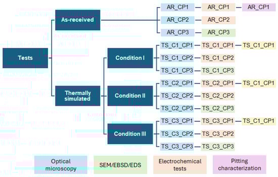
Figure 1.
Flowchart of tests and specimens.
2.1. Material
As mentioned, the material used in this study was the super-duplex stainless steel UNS S32750, in the form of plates with a thickness of 10 mm. The as-received condition corresponds to the hot-rolled steel heat-treated at 1100 °C and water-quenched. All characterization took place on the face perpendicular to the rolling direction. The chemical composition of the material, according to the material datasheet provided by the supplier, and its corresponding pitting resistance equivalent number (PREN) are presented in Table 1. The method for calculating PREN is described in Equation (1), using the weight percentages of each element:
PREN = %Cr + 3.3%Mo + 16%N

Table 1.
Chemical composition of the AISD UNS S32750 steel (wt%; balance: Fe).
2.2. Physical Simulation
The physical simulation was designed to replicate the HTHAZ of a single-pass weld, with a thermal history described as a sequence of heating and cooling cycles [27,28,29]. The HTHAZ was chosen because it is critical for the performance of the SDSS. High ferrite fractions in this region can significantly impact the material’s corrosion resistance and mechanical properties [30]. A Gleeble 540® Welding Simulator (Poestenkill, NY, USA) was used to simulate three different heat input conditions—low (C1), medium (C2), and high (C3)—in specimens with dimensions of 75 × 10 × 10 mm (L × W × H) [16]. According to the literature, a peak temperature of 1350 °C was defined to represent the HTHAZ [16,27]. To obtain the thermal cycle for each condition, the ratio between cooling times from 800 to 500 °C (∆t8/5) and from 1200 to 800 °C (∆t12/8) was kept around 3.0, according to Equation (2), where T0 is the initial temperature (25 °C) [27,29].
The relationship between heat input and ∆t8/5 is given by Equation (3), where Q is the heat input (J/mm), d is the thickness of the material (mm), and k is the thermal coefficient (kJ/mm2s1/2). For this material, a coefficient of 25.52 kJ/mm2s1/2 was considered [27,29].
Table 2 presents the conditions studied with their respective values of cooling rates (CRs), associated times, and heat inputs (Q), for the peak temperature of 1350 °C, whose values were obtained by the equations above. As shown in Figure 1, three repetitions were performed for each condition, totaling nine samples.
Table 2.
Parameters considered for each condition.
Thermal cycles were input as scripts into Gleeble’s QuikSim2 software. The heating rate was set at 350 °C/s for all conditions, and compressed air was used as the cooling medium. A K-type thermocouple was spot-welded onto the specimen’s surface in its mid-length position for temperature control and acquisition. All subsequent characterization was performed on the cross-sections of specimens aligned with the thermocouple’s placement. Graphical representations of the three thermal cycles are shown in Figure 2.
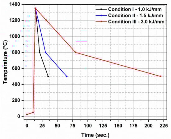
Figure 2.
Thermal curves used for the three different conditions.
2.3. Microstructural Characterization
Both as-received and Gleeble-processed conditions were analyzed by optical microscopy (OM), scanning electron microscopy with energy-dispersive spectroscopy (SEM/EDS), and electron backscatter diffraction (EBSD). For all analyses, specimens machined for Gleeble simulations were cut in their mid-length position to expose the 10 × 10 mm cross-section. Cross-sections were mechanically ground up to the 2000 mesh sandpaper and polished with 1 µm and 0.3 µm alumina suspensions. For corrosion tests, specimens were further cold-embedded with a copper wire to provide electrical contact.
Specimens were etched with Behara II (20 mL of hydrochloric acid in of 100 mL distilled water with the addition of 0.6 g of potassium metabisulfite) for OM [31]. Phase quantification under the light microscope (Zeiss Axio Scope.A1 equipped with an Axiocam ERc 5s camera, Oberkochen, Germany) was carried out by acquiring 04 (four) images with a magnification of 100× in each specimen and post-processing using thresholding by color contrast in the open software ImageJ 1.53 to obtain area fractions of ferrite and austenite.
For SEM, the Murakami electrolytic etching procedure was used to reveal grain boundaries after mechanical polishing, using an aqueous solution of potassium hydroxide with a 3:7 volume proportion and the application of a 3 V tension for 7 s [32]. Specimens were then analyzed in a JEOL JSM-6510LV tungsten microscope operated (Tokyo, Japan) at 20 kV equipped with a Thermo Fisher UltraDry detector (Waltham, MA, USA) for semiquantitative energy-dispersive spectroscopy (EDS) analyses. Five spot measurements were conducted in each phase to obtain their average composition.
Finally, for EBSD, mechanically polished specimens were subjected to electrolytic polishing using a mixed solution of phosphoric and sulfuric acids with a 3:1 volume proportion at 70 °C, under a current of 5 A for one minute [33]. EBSD analyses were carried out under the same SEM using a Bruker eFlash FS detector (Billerica, MA, USA) with a step size of 0.2 µm. Data processing was performed in the Bruker Esprit 2.5 software.
2.4. Electrochemical Tests
For electrochemical tests, a cell based on Daniell’s cell was used, aiming to preserve the integrity of the reference electrode during high-temperature tests, according to the ASTM G5 (2004) standard [34]. In one cell, specimens were placed in a 3.5% (m/V) NaCl solution, simulating a marine environment, together with the Pt counter-electrode, where heating takes place. A saline bridge made of agar-agar in a 1.0 M KCl solution links the heated cell to the other cell, containing the Ag/AgCl reference electrode immersed in a 3.0 M KCl solution at room temperature. All electrodes were connected to an Autolab Metrohm PGSTAT128N potentiostat/galvanostat (Utrecht, The Netherlands). The NOVA 2.1 software was used for data extraction and Tafel extrapolation [12,34,35].
Tests were performed with a scanning rate of 1.0 mV/s, from −1500 mV to +1500 mV. Before each run, the open-circuit potential (OCP) was kept for one hour until its stabilization. Different temperatures were used to define the CPT of each condition, as shown in Table 3. Firstly, the as-received condition was tested in temperatures ranging from 30 °C to 90 °C to define the relevant test interval to understand the material’s behavior; this interval (40–70 °C) was then used to characterize simulated conditions. To determine the CPT, linear curves were traced tangential to the passive and transpassive regions of the polarization curve. The pitting potential (Epitting) corresponds to the intersection point of both curves [35,36,37]. With these values, it was possible to plot the pitting potential as function of temperature. The CPT is defined as the inflection point of the fitted polynomial curve. Two specimens of each condition were used to draw the polarization curves to ensure repeatability.
Table 3.
Test temperatures used for CPT determination.
3. Results and Discussion
3.1. Physical Simulation
The curves obtained after simulation of the HTHAZ, plotted against the calculated curves for comparison, are presented in Figure 3. The nearly perfect superimposition between simulated curves for each condition indicates the repeatability of the technique. Moreover, experimental curves are sufficiently close to the calculated one in all cases. The peak temperature was approximately 1340 °C for all tested conditions, close to the target value of 1350 °C. Cooling curves showed a maximum difference of 13% with respect to the target values in the ∆t12/5 region of condition I, which can be explained by the higher cooling rate.
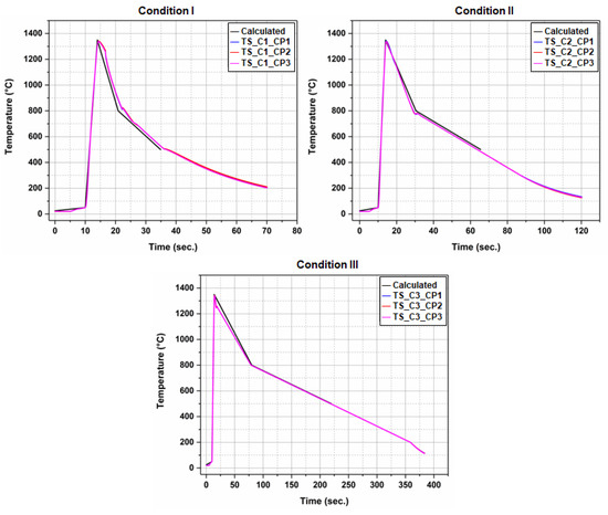
Figure 3.
Experimental curves obtained after simulation of HTHAZ along with the reference (calculated) curve for all conditions.
3.2. Microstructure
OM images of the as-received steel and conditions I-III are shown in Figure 4, along with the respective area fractions measured for ferrite (dark phase). After thermal cycles, the amount of ferrite increased, which is expected since austenite partially transforms into ferrite, and cooling rates are not slow enough to allow all ferrite to transform back into austenite [38]. However, it did not vary significantly between heat-treated conditions, especially considering the standard deviation, although a slight tendency of increase in ferrite fraction with decreasing cooling rate can be observed. On the other hand, the evolution of phase morphology and grain size is notable. After heat treatment, Widmanstätten morphology, usually expected in the HTHAZ of super-duplex steels, can be observed. No secondary phases, such as sigma or chi, were detected by OM [10,14,39]. Phase maps obtained by EBSD, depicted in Figure 5, show no signal of sigma and chi phases either.
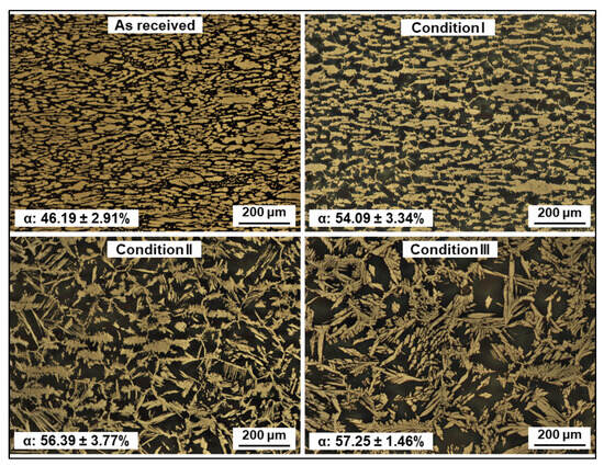
Figure 4.
Optical microscopy images showing the microstructure of the super-duplex steel in all studied conditions, along with respective ferrite fractions obtained by image analysis. The rolling direction is parallel to the width of the images.
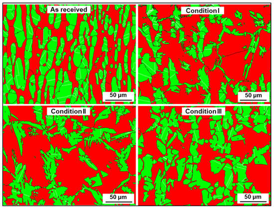
Figure 5.
EBSD phase maps showing ferrite (red) and austenite (green). The rolling direction is parallel to the height of the images.
The average compositions of each phase obtained by EDS are summarized in Table 4, while maps showing element distribution in the as-received condition are presented in Figure 6, with Ni enrichment in austenite and Cr and Mo enrichment in ferrite. Because the technique has limitations when it comes to the detection and quantification of light elements, such as carbon (C) and nitrogen (N), these elements were not considered in the analysis [10,40,41,42]. Alternatively, for the calculation of the PREN, C and N amounts were taken from the material datasheet provided by the manufacturer (0.015% and 0.27%, respectively), while the concentration of other elements was determined using the EDS technique. Molybdenum’s behavior was the same in both phases, decreasing in comparison with the as-received condition and gradually increasing with decreasing cooling rate. In opposition, the Cr concentration increases discretely. PREN evolution is graphically represented in Figure 7, where one can notice that PREN decreases after thermal cycles in both phases, with a tendency to increase with decreasing cooling rate (and increasing ferrite fraction).
Table 4.
Summarized compositions of ferrite and austenite obtained by EDS and resulting PREN (balance: Fe).
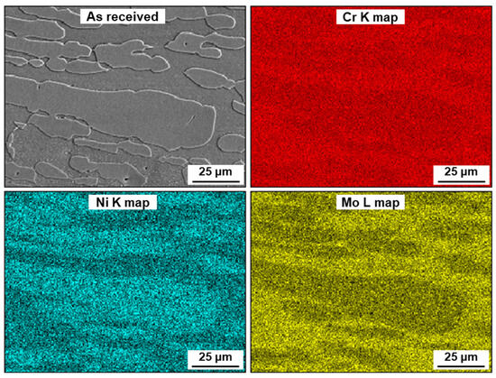
Figure 6.
EDS maps showing Cr, Ni, and Mo distribution in the as-received condition. The rolling direction is parallel to the width of the images.
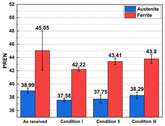
Figure 7.
PREN evolution in ferrite and austenite after the application of different cycles.
3.3. Potentiodynamic Polarization and Critical Pitting Temperature (CPT)
Figure 8 presents the potentiodynamic polarization curves of the super-duplex steel in NaCl solution, from which the pitting potentials (Ep) were extracted, as indicated by the arrows. The figure shows results of tests conducted at temperatures ranging from 30 °C to 90 °C for the material in the as-received condition, and from 40 °C to 70 °C for the thermally simulated samples.
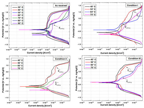
Figure 8.
Potentiodynamic polarization curves in 3.5% (m/V) NaCl solution, for as-received and heat-treated conditions.
The pitting potentials (Ep) for the as-received condition were around 1 V vs. Ag/AgCl, indicating high resistance to pitting corrosion at temperatures up to 50 °C. The passive region appeared continuous, with minimal noise, perpendicular, and without repassivation segments. In this case, temperature was the only factor responsible for the decrease in pitting corrosion resistance in the as-received condition.
In the thermally simulated conditions, repassivation events were observed, occurring when the passive layer weakens in certain areas, initiating metastable pitting corrosion. Similar to the as-received condition, the curves for lower temperatures, 40 °C and 50 °C, in all three conditions showed a larger and more stable passive region than those at higher temperatures. The curves exhibited a slope along their length, indicating instability in the formation of the passive film, suggesting that thermal cycling significantly influences the corrosion resistance of super-duplex steels. This behavior may be related to microstructural variations due to an imbalance in the amount of austenite and ferrite, resulting in different electrochemical passivation mechanisms and generating localized galvanic activity.
The critical pitting temperature (CPT) presented in Figure 9 was determined by the inflection point of the polynomial curve, based on the pitting potential values extracted from the potentiodynamic polarization curves. For the as-received condition, the average Ep was 1.0102 ± 0.32 V vs. Ag/AgCl at temperatures of 50 °C, 60 °C, and 70 °C, dropping to 0.17741 V vs. Ag/AgCl at 90 °C. This value is observed when the current density increases due to the breakdown of the passive film, indicating that the steel exhibits low corrosion resistance at higher temperatures.
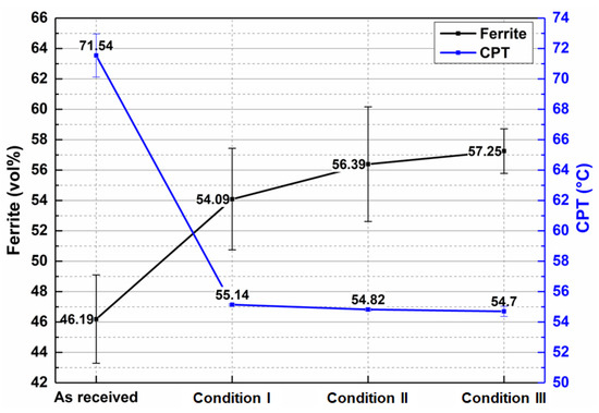
Figure 9.
Correlation between CPT and ferrite amount in all conditions.
A similar effect was observed in thermally treated samples, where the Ep values ranged from 54.87 ± 0.049 V vs. Ag/AgCl at 40 °C and 50 °C to −0.004 ± 0.127 V vs. Ag/AgCl at 70 °C. The thermally simulated samples displayed very close CPTs, with an average value of 54.89 °C, while the as-received material showed higher corrosion resistance, with a CPT of 71.54 °C. Therefore, both pitting potential and CPT values confirm the reduction in pitting corrosion resistance of super-duplex steel after thermal treatments [43].
Pitting corrosion resistance, although largely governed by the alloying elements represented by the pitting resistance equivalent number (PREN)—where higher values indicate greater corrosion resistance—is not the sole determining factor in measuring corrosion resistance in duplex stainless steels [44]. The PREN does not account for all the factors influencing electrochemical balance, such as surface roughness, heterogeneous particles, and local variations in the passive film, which can lead to inaccurate conclusions when considered alone [44,45,46,47].
In the work of Pecly et al. [48], the effect of cooling in the heat-affected zone of duplex UNS S32205 and super-duplex UNS S32750 steels was analyzed, revealing that the increase in ferrite fraction was the main factor contributing to the reduction in corrosion resistance. Austenite generally exhibits a higher corrosion potential compared to ferrite, due to the distribution of alloying elements in each phase, as Cr and Mo stabilize the ferritic phase, while Ni and N stabilize the austenitic phase. However, it was also confirmed that the distribution of alloying elements in each phase varies with heat treatment, which can alter the phase balance and thereby reduce corrosion resistance [49]. For this reason, corrosion tends to occur at the δ/γ phase interface or within ferrite phase domains. Several researchers [50,51,52] report that thermal treatments with high cooling rates result in a decrease in the austenitic phase, leading to a reduction in overall pitting corrosion resistance.
The relationship between the increase in ferrite fraction and the decrease in CPT is shown in Figure 9. The as-received material exhibited 46.19% ferrite and achieved the highest corrosion resistance, with a CPT of 71.54 °C. Thermally simulated samples showed ferrite fractions that were very close, ranging between 54.09% and 57.25%, as well as similar CPT values. This corroborates that the predominant mechanism in the reduction of CPT in thermally simulated samples was the increase in the ferrite phase.
The microstructure of the different conditions after polarization tests conducted at 70 °C (as-received) and 50 °C (conditions I–III) is shown in Figure 10. In the as-received condition, pitting corrosion occurred primarily in ferritic grains, especially at ferrite (δ)/austenite (γ) interfaces. After thermal cycling, however, the pits were larger in size and fewer in number, indicating the increased severity of the attack. This increased pitting severity can be attributed to the fact that thermal cycling leads to greater reductions in PREN in the latter phase (6.28% in condition I, 3.64% in condition II, and 2.77% in condition III), as shown in Figure 7.
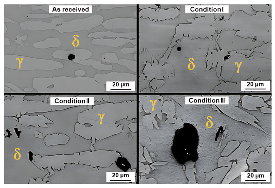
Figure 10.
SEM images showing the microstructures of the as-received condition after polarization tests at 70 °C and of conditions I–III after polarization tests at 50 °C. The black regions correspond to the pits formed after polarization.
4. Conclusions
In this study, a SDSS UNS S32750 steel was submitted to physical simulations of the HTHAZ, aiming to reproduce typical thermal cycles of single-pass arc welding at three different heat inputs (low, medium, and high)—1.0, 1.5, and 3.0 kJ/mm—using a Gleeble® simulator. By microstructural and electrochemical assessment of simulated specimens, it was possible to draw the following conclusions:
- All conditions experienced an increase in ferrite amount with respect to the as-received material, which is an expected consequence of the thermal input. Differences in phase morphologies through all conditions were noticeable, with the presence of Widmanstätten austenite and small portions of secondary austenite. Deleterious phases, such as sigma or chi, were not detected either by conventional OM, SEM, or EBSD characterization.
- Super-duplex steel, in the “as-received” condition, exhibits excellent pitting corrosion resistance, with an average pitting potential (Ep) of approximately 1 V vs. Ag/AgCl at temperatures up to 50 °C, indicating stable passive film formation. However, as the temperature increases to 90 °C, resistance drops sharply, with the pitting potential falling to 0.17741 V, highlighting greater susceptibility to corrosion due to the breakdown of the passive layer. In the thermally treated samples, pitting corrosion resistance was significantly reduced. This behavior was evidenced by the polarization curves, which did not show a uniform passive region and exhibited multiple passivation, indicating a complex electrochemical behavior in response to variations in the applied potential.
- The critical pitting temperature (CPT) of the treated samples was lower than that of the “as-received” condition (71.54 °C), with values of 55.14 °C, 54.82 °C, and 54.7 °C for conditions I, II, and III, respectively. This result suggests that the increase in ferrite fraction observed in the simulated samples is the main factor responsible for the reduction in corrosion resistance. It was possible to correlate chemical composition with the preferential location of pits at temperatures close to CPT: in the as-received material, corrosion occurred preferentially in austenitic grains and grain boundaries due to the difference in chemical composition of ferrite and austenite phases. After thermal cycling, however, pitting occurred preferentially in ferritic regions.
- To prevent the loss of corrosion resistance and unbalanced microstructure, it is important to control welding parameters such as current, voltage, and heat input. Using filler materials with austenitizing elements helps to prevent an increase in ferrite. Additionally, using appropriate shielding and purge gases is crucial to avoid contamination of the material. Mechanizing the welding process can help prevent significant variations in welding parameters. Proper control of welding time and temperature is essential to avoid the formation of deleterious phases and ensure a balanced microstructure.
Author Contributions
Conceptualization, F.M.d.S.J., T.N.L. and R.S.C.; methodology, F.M.d.S.J., L.O.P.d.S., B.C. and T.N.L.; formal analysis, F.M.d.S.J., L.O.P.d.S., Y.T.B.d.S., B.C. and T.N.L.; investigation, F.M.d.S.J., L.O.P.d.S. and Y.T.B.d.S.; resources, L.O.P.d.S. and F.M.d.S.J.; writing—original draft preparation, L.O.P.d.S., Y.T.B.d.S., B.C. and T.N.L.; writing—review and editing, F.M.d.S.J., L.O.P.d.S., Y.T.B.d.S., B.C. and T.N.L.; visualization, B.C.; supervision, R.S.C.; project administration, T.N.L.; funding acquisition, R.S.C. All authors have read and agreed to the published version of the manuscript.
Funding
This research was funded by the ANP/PETROBRAS program (SAP 4600580712).
Data Availability Statement
The original contributions presented in this study are included in the article. Further inquiries can be directed to the corresponding author.
Acknowledgments
The authors would like to acknowledge the post-graduate program GETEC at SENAI CIMATEC and ANP/PETROBRAS for their financial support to this project.
Conflicts of Interest
The authors declare no conflicts of interest.
References
- Han, Y.; Chi, R.; Chen, Q.; Wang, B.; Liu, W.; He, Y. Microstructural Evolution and Coarsening Behavior of the Precipitates in 2205 Duplex Stainless Steel Aged at 850 °C. J. Mater. Res. Technol. 2023, 26, 2560–2574. [Google Scholar] [CrossRef]
- Arun, D.; Devendranath Ramkumar, K.; Vimala, R. Multi-Pass Arc Welding Techniques of 12 mm Thick Super-Duplex Stainless Steel. J. Mater. Process Technol. 2019, 271, 126–143. [Google Scholar] [CrossRef]
- Sakata, M.; Kadoi, K.; Inoue, H. Age-Hardening Behaviors of the Weld Metals of 22% Cr and 25% Cr Duplex Stainless Steels at 400 °C. J. Nucl. Mater. 2023, 581, 154438. [Google Scholar] [CrossRef]
- Zhang, Z.; Jing, H.; Xu, L.; Han, Y.; Zhao, L. Investigation on Microstructure Evolution and Properties of Duplex Stainless Steel Joint Multi-Pass Welded by Using Different Methods. Mater. Des. 2016, 109, 670–685. [Google Scholar] [CrossRef]
- Acuna, A.; Ramirez, A.J. Sigma Phase Formation Kinetics in Hyper Duplex Stainless Steel Welding Filler Metal. Mater. Charact. 2023, 200, 112832. [Google Scholar] [CrossRef]
- Llorca-Isern, N.; López-Luque, H.; López-Jiménez, I.; Biezma, M.V. Identification of Sigma and Chi Phases in Duplex Stainless Steels. Mater. Charact. 2016, 112, 20–29. [Google Scholar] [CrossRef]
- Dornelas, P.H.; Payão Filho, J.D.; Moraes e Oliveira, V.H.; Farias, F.W. Influence of Interpass Temperature on the Simulated Coarse-Grained Heat-Affected Zone of a Circumferentially Welded 2.25Cr-1Mo Steel Pipe Joint. J. Manuf. Mater. Process. 2024, 8, 248. [Google Scholar] [CrossRef]
- Garzón, C.M.; Serna, C.A.; Brandi, S.D.; Ramirez, A.J. The Relationship between Atomic Partitioning and Corrosion Resistance in the Weld-Heat Affected Zone Microstructures of UNS S32304 Duplex Stainless Steel. J. Mater. Sci. 2007, 42, 9021–9029. [Google Scholar] [CrossRef]
- Zhang, Z.; Jing, H.; Xu, L.; Han, Y.; Zhao, L.; Lv, X. Effect of Post-Weld Heat Treatment on Microstructure Evolution and Pitting Corrosion Resistance of Electron Beam-Welded Duplex Stainless Steel. Corros. Sci. 2018, 141, 30–45. [Google Scholar] [CrossRef]
- Khalfallah, A.; Moradi, M.; Beygi, R. Welding and Joining of Metallic Materials: Microstructure and Mechanical Properties. Crystals 2024, 14, 839. [Google Scholar] [CrossRef]
- Jiang, Y.; Tan, H.; Wang, Z.; Hong, J.; Jiang, L.; Li, J. Influence of Creq/Nieq on Pitting Corrosion Resistance and Mechanical Properties of UNS S32304 Duplex Stainless Steel Welded Joints. Corros. Sci. 2013, 70, 252–259. [Google Scholar] [CrossRef]
- Yang, Y.; Guo, Y.; Liu, Y.; Li, J.; Jiang, Y. The Microstructure and Pitting Resistance of 2002 Lean Duplex Stainless Steel after the Simulated Welding Thermal Cycle Process. Materials 2019, 12, 70. [Google Scholar] [CrossRef] [PubMed]
- A Hosseini, V.; Karlsson, L. Physical and Kinetic Simulation of Nitrogen Loss in High Temperature Heat Affected Zone of Duplex Stainless Steels. Materialia 2019, 6, 100325. [Google Scholar] [CrossRef]
- Acuna, A.; Riffel, K.C.; Ramirez, A. A Comparison of Sigma Phase Formation in Solubilized Hyper Duplex Stainless Steel and Super Duplex Stainless Steel Filler Metals. Met. Mater. Trans. A Phys. Met. Mater. Sci. 2024, 55, 2881–2896. [Google Scholar] [CrossRef]
- Tan, H.; Wang, Z.; Jiang, Y.; Yang, Y.; Deng, B.; Song, H.; Li, J. Influence of Welding Thermal Cycles on Microstructure and Pitting Corrosion Resistance of 2304 Duplex Stainless Steels. Corros. Sci. 2012, 55, 368–377. [Google Scholar] [CrossRef]
- da Silva, L.O.P.; Lima, T.N.; Júnior, F.M.d.S.; Callegari, B.; Folle, L.F.; Coelho, R.S. Heat-Affected Zone Microstructural Study via Coupled Numerical/Physical Simulation in Welded Superduplex Stainless Steels. Crystals 2024, 14, 204. [Google Scholar] [CrossRef]
- Guo, Y.; Sun, T.; Hu, J.; Jiang, Y.; Jiang, L.; Li, J. Microstructure Evolution and Pitting Corrosion Resistance of the Gleeble-Simulated Heat-Affected Zone of a Newly Developed Lean Duplex Stainless Steel 2002. J. Alloys Compd. 2016, 658, 1031–1040. [Google Scholar] [CrossRef]
- Cojocaru, E.M.; Raducanu, D.; Nocivin, A.; Cojocaru, V.D. Influence of Ageing Treatment Temperature and Duration on σ-Phase Precipitation and Mechanical Properties of UNS S32750 SDSS Alloy. J. Adv. Res. 2021, 30, 53–61. [Google Scholar] [CrossRef] [PubMed]
- Gutiérrez-Vargas, G.; Ruiz, A.; López-Morelos, V.H.; Kim, J.Y.; González-Sánchez, J.; Medina-Flores, A. Evaluation of 475 °C Embrittlement in UNS S32750 Super Duplex Stainless Steel Using Four-Point Electric Conductivity Measurements. Nucl. Eng. Technol. 2021, 53, 2982–2989. [Google Scholar] [CrossRef]
- Shrivastava, R.; Maurya, R.; Katiyar, P.K. Examining Sigma Phase in Super Duplex Stainless Steels (UNS S32750) after Isothermal Aging, Focusing on Its Influence on Etching and Pitting Corrosion with Optical Microscopy. Metallogr. Microstruct. Anal. 2024, 13, 741–763. [Google Scholar] [CrossRef]
- Ajay, E.; Prasad, A.D.V.; Rao, A.G.; Raja, V.S. Role of Microstructure on the Varying Corrosion Behavior across the UNS S32750 Super Duplex Stainless Steel Friction Stir Weld. J. Mater. Sci. 2024, 2024, 1–19. [Google Scholar] [CrossRef]
- Borges, F.M.R.; Borges, W.F.A.; Santos, R.L.P.; Leal, V.S.; dos Santos Júnior, J.R.; Lobo, A.O.; de Sousa, R.R.M. Corrosion Resistance and Microstructural Evaluation of a Plasma Nitrided Weld Joint of UNS S32750 Super Duplex Stainless Steel. Mater. Res. 2021, 24, e20210087. [Google Scholar] [CrossRef]
- Devendranath Ramkumar, K.; Thiruvengatam, G.; Sudharsan, S.P.; Mishra, D.; Arivazhagan, N.; Sridhar, R. Characterization of Weld Strength and Impact Toughness in the Multi-Pass Welding of Super-Duplex Stainless Steel UNS 32750. Mater. Des. 2014, 60, 125–135. [Google Scholar] [CrossRef]
- Zhang, Z.; Zhang, H.; Hu, J.; Qi, X.; Bian, Y.; Shen, A.; Xu, P.; Zhao, Y. Microstructure Evolution and Mechanical Properties of Briefly Heat-Treated SAF 2507 Super Duplex Stainless Steel Welds. Constr. Build. Mater. 2018, 168, 338–345. [Google Scholar] [CrossRef]
- de Farias Azevedo, C.R.; Boschetti Pereira, H.; Wolynec, S.; Padilha, A.F. An Overview of the Recurrent Failures of Duplex Stainless Steels. Eng. Fail. Anal. 2019, 97, 161–188. [Google Scholar] [CrossRef]
- Tavares, S.S.M.; Pardal, J.M.; Almeida, B.B.; Mendes, M.T.; Freire, J.L.F.; Vidal, A.C. Failure of Superduplex Stainless Steel Flange Due to Inadequate Microstructure and Fabrication Process. Eng. Fail. Anal. 2018, 84, 1–10. [Google Scholar] [CrossRef]
- Liou, H.-Y.; Hsieh, R.-I.; Tsai, W.-T. Microstructure and Stress Corrosion Cracking in Simulated Heat-Affected Zones of Duplex Stainless Steels. Corros. Sci. 2002, 44, 2841–2856. [Google Scholar] [CrossRef]
- Reccagni, P.; Guilherme, L.H.; Lu, Q.; Gittos, M.F.; Engelberg, D.L. Reduction of Austenite-Ferrite Galvanic Activity in the Heat-Affected Zone of a Gleeble-Simulated Grade 2205 Duplex Stainless Steel Weld. Corros. Sci. 2019, 161, 108198. [Google Scholar] [CrossRef]
- Yang, Y.; Yan, B.; Li, J.; Wang, J. The Effect of Large Heat Input on the Microstructure and Corrosion Behaviour of Simulated Heat Affected Zone in 2205 Duplex Stainless Steel. Corros. Sci. 2011, 53, 3756–3763. [Google Scholar] [CrossRef]
- Zhang, Z.; Jing, H.; Xu, L.; Han, Y.; Gao, Z.; Zhao, L.; Zhang, J. Microstructural Characterization and Electron Backscatter Diffraction Analysis across the Welded Interface of Duplex Stainless Steel. Appl. Surf. Sci. 2017, 413, 327–343. [Google Scholar] [CrossRef]
- Cláudia, T.; Farias, C.; Tadeu, Y.; Henrique, D.; Zanini, S.; Coelho, R.; Simas Filho, E.; Silva, I. Influence of Deleterious Phases in Super-Duplex Steel SAF 2507 in the Ultrasonic Lamb Waves Propagation. In Proceedings of the 11th European Conference on Non-Destructive Testing (ECNDT 2014), Prague, Czech Republic, 6–11 October 2014. [Google Scholar]
- Putz, A.; Althuber, M.; Zelić, A.; Westin, E.; Willidal, T.; Enzinger, N. Methods for the Measurement of Ferrite Content in Multipass Duplex Stainless Steel Welds. Weld. World 2019, 63, 1075–1086. [Google Scholar] [CrossRef]
- Huang, C.A.; Hsu, C. The Electrochemical Polishing Behavior of Duplex Stainless Steel (SAF 2205) in Phosphoric-Sulfuric Mixed Acids. Int. J. Adv. Manuf. Technol. 2007, 34, 904–910. [Google Scholar] [CrossRef]
- ASTM International. ASTM G5—Standard Reference Test Method for Making Potentiodynamic Anodic Polarization Measurements. In Book 03.02, Standards Volume; Astm International: West Conshohocken, PA, USA, 2004. [Google Scholar]
- Souza, J.P.B.d; Arias, A.d.G.; Pardal, J.M.; Mainier, F.B.; Ferreira, M.L.R.; Tavares, S.S.M. Análise Da Resistência à Corrosão Por Pite Em Soldas de Reparo Pelo Processo TIG Em Aço Inoxidável Superduplex UNS S32750. Soldag. Inspeção 2011, 16, 104–113. [Google Scholar] [CrossRef]
- Ferreira, M.L.R.; Silva, C.A.F.d.; Pardal, J.M.; Tavares, S.S.M. Influência Dos Gases de Proteção Na Soldagem Do Aço UNS S31803 Com Arame E2209-T1/4 Pelo Processo FCAW. Soldag. Inspeção 2018, 23, 309–325. [Google Scholar] [CrossRef]
- Sawczen, T. Electrochemical Characterization and Proposed Methodology for the Determination of Critical Pitting Temperature of UNS S32760 Super Duplex Stainless Steel; USP: North Bethesda, MD, USA, 2014. [Google Scholar]
- Higelin, A.; Le Manchet, S.; Passot, G.; Cissé, S.; Grocki, J. Heat-Affected Zone Ferrite Content Control of a Duplex Stainless Steel Grade to Enhance Weldability. Weld. World 2022, 66, 1503–1519. [Google Scholar] [CrossRef]
- Souza, C.S.; Lins, V.d.F.C.; Silveira, D.M.d.; Costa, C.G.F.; Cardoso Junior, R.; Campos, F.R.; Bracarense, A.Q. Avaliação Da Soldagem Multipasse de Chapas Espessas de Aços Inoxidáveis Lean Duplex UNS S32304 Soldadas Pelos Processos SMAW, GMAW e FCAW -: Resistência à Corrosão. Soldag. Inspeção 2013, 18, 257–267. [Google Scholar] [CrossRef]
- Verma, J.; Taiwade, R.V. Effect of Welding Processes and Conditions on the Microstructure, Mechanical Properties and Corrosion Resistance of Duplex Stainless Steel Weldments—A Review. J. Manuf. Process 2017, 25, 134–152. [Google Scholar] [CrossRef]
- Li, G.; Wang, J.; Wu, T.; Wen, Y.; Li, H.; Liu, C. Microstructure and Mechanical Properties of 2205 DSS Metal Inert-Gaswelding Joints. Cailiao Yanjiu Xuebao/Chin. J. Mater. Res. 2016, 30, 897–902. [Google Scholar] [CrossRef]
- Que, Z.; Ahonen, M.; Virkkunen, I.; Nevasmaa, P.; Rautala, P.; Reinvall, H. Study of Cracking and Microstructure in Co-Free Valve Seat Hardfacing. Nucl. Mater. Energy 2022, 31, 101202. [Google Scholar] [CrossRef]
- Gholami, M.; Hoseinpoor, M.; Moayed, M.H. A Statistical Study on the Effect of Annealing Temperature on Pitting Corrosion Resistance of 2205 Duplex Stainless Steel. Corros. Sci. 2015, 94, 156–164. [Google Scholar] [CrossRef]
- Ran, G.; Tu, W.; Dong, H.; Jiang, Y.; Li, J.; Liu, K.; Sun, Y. Comparative Statistical Analysis of Pitting in Two 2205 Duplex Stainless Steel Variants. npj Mater. Degrad. 2024, 8, 30. [Google Scholar] [CrossRef]
- Wang, R. Precipitation of Sigma Phase in Duplex Stainless Steel and Recent Development on Its Detection by Electrochemical Potentiokinetic Reactivation:A Review. Corros. Commun. 2021, 2, 41–54. [Google Scholar] [CrossRef]
- Ma, L.; Wiame, F.; Maurice, V.; Marcus, P. Origin of Nanoscale Heterogeneity in the Surface Oxide Film Protecting Stainless Steel against Corrosion. npj Mater. Degrad. 2019, 3, 29. [Google Scholar] [CrossRef]
- Tan, X.; Jiang, Y.; Chen, Y.; Tong, A.; Li, J.; Sun, Y. Roles of Different Components of Complex Inclusion in Pitting of 321 Stainless Steel: Induction Effect of CaS and Inhibition Effect of TiN. Corros. Sci. 2022, 209, 110692. [Google Scholar] [CrossRef]
- Pecly, P.H.R.; Almeida, B.B.; Perez, G.; Pimenta, A.R.; Tavares, S.S.M. Microstructure, Corrosion Resistance, and Hardness of Simulated Heat-Affected Zone of Duplex UNS S32205 and Superduplex UNS S32750 Stainless Steels. J. Mater. Eng. Perform. 2023, 32, 9019–9028. [Google Scholar] [CrossRef]
- Nithin Raj, P.; Sivan, A.P.; Sekar, K.; Joseph, M.A. Effect of Austenite Reformation on Localized Corrosion Resistance of Hyper-Duplex Stainless Steel in Hot Chloride Solution. Int. J. Met. 2020, 14, 167–178. [Google Scholar] [CrossRef]
- Tan, H.; Jiang, Y.; Deng, B.; Sun, T.; Xu, J.; Li, J. Effect of Annealing Temperature on the Pitting Corrosion Resistance of Super Duplex Stainless Steel UNS S32750. Mater. Charact. 2009, 60, 1049–1054. [Google Scholar] [CrossRef]
- Guo, L.Q.; Li, M.; Shi, X.L.; Yan, Y.; Li, X.Y.; Qiao, L.J. Effect of Annealing Temperature on the Corrosion Behavior of Duplex Stainless Steel Studied by in Situ Techniques. Corros. Sci. 2011, 53, 3733–3741. [Google Scholar] [CrossRef]
- Zhang, L.; Zhang, W.; Jiang, Y.; Deng, B.; Sun, D.; Li, J. Influence of Annealing Treatment on the Corrosion Resistance of Lean Duplex Stainless Steel 2101. Electrochim. Acta 2009, 54, 5387–5392. [Google Scholar] [CrossRef]


Disclaimer/Publisher’s Note: The statements, opinions and data contained in all publications are solely those of the individual author(s) and contributor(s) and not of MDPI and/or the editor(s). MDPI and/or the editor(s) disclaim responsibility for any injury to people or property resulting from any ideas, methods, instructions or products referred to in the content. |
© 2024 by the authors. Licensee MDPI, Basel, Switzerland. This article is an open access article distributed under the terms and conditions of the Creative Commons Attribution (CC BY) license (https://creativecommons.org/licenses/by/4.0/).