
Effect of Post-Weld Heat Treatment Cooling Strategies on Microstructure and Mechanical Properties of 0.3 C-Cr-Mo-V Steel Weld Joints Using GTAW Process

 ,
,  , , , and
Abstract
1. Introduction
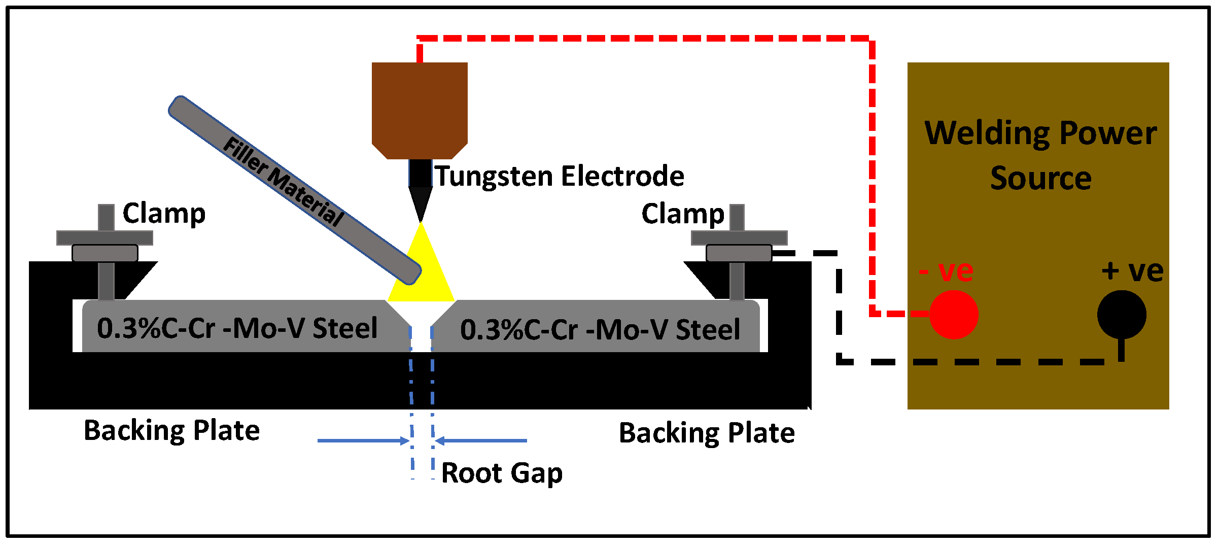
2. Materials and Methods
3. Results and Discussion
3.1. Correlation of Heat Input, Filler Usage, and Weld Bead Geometry
3.2. Microstructure Characterization
3.3. Mechanical Properties
3.3.1. Testing Hardness
3.3.2. Tensile and Impact Testing
4. Conclusions
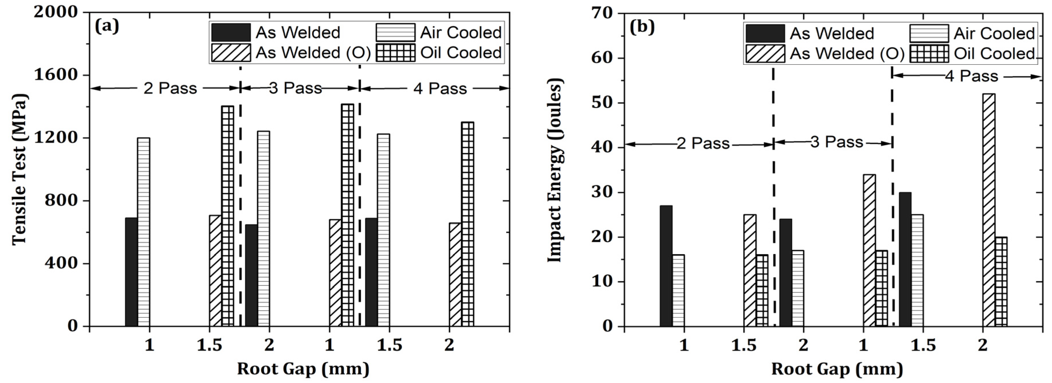
- As-welded specimens exhibited tensile strengths ranging from 650 to 690 MPa, with failure occurring at the HAZ–base metal interface, indicating that the weldment retained high strength. The weld joint efficiency exceeded 90%, aligning with the literature.
- An increase in the number of passes resulted in lower tensile strength but improved ductility and impact toughness, accentuating the inverse relationship between hardness and toughness.
- OC produced a fine martensitic–bainitic microstructure, leading to higher tensile strength than AC, though with slightly reduced ductility. PWHT enhanced impact toughness while maintaining hardness, leading to a more balanced mechanical performance. The OC offered a refined microstructure and an optimal combination of strength and toughness.
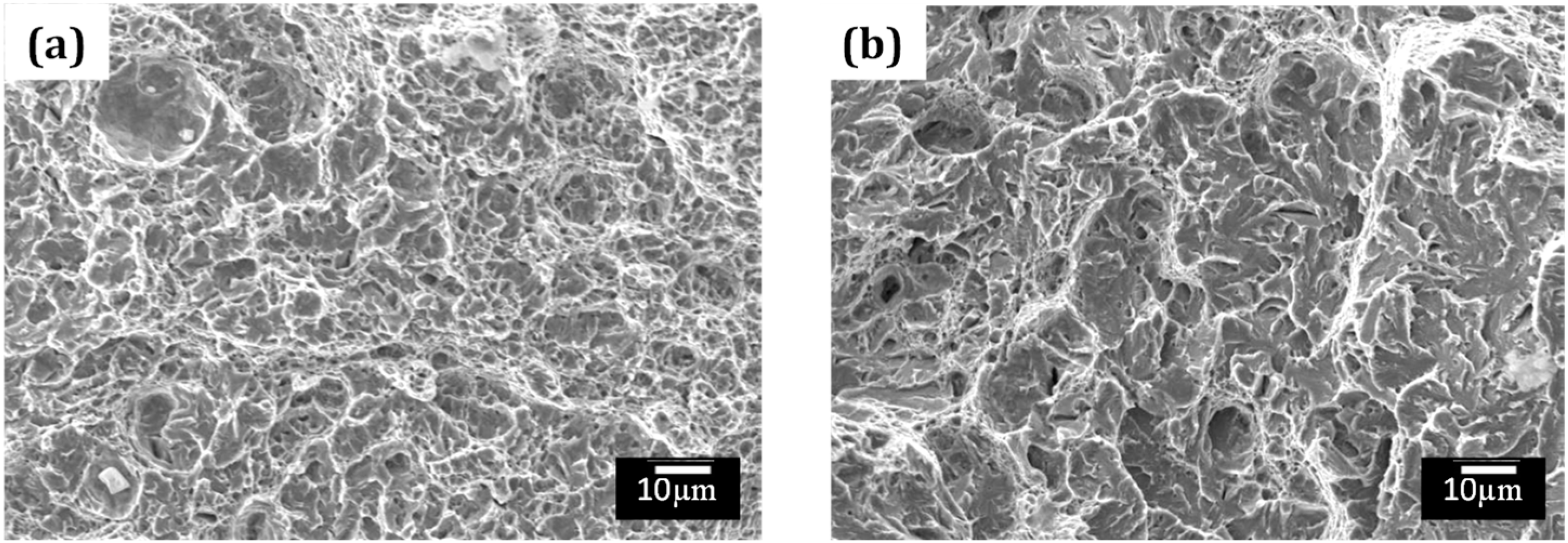
- Fractography analysis showed that OC samples had a mixed ductile–brittle failure mode, while AC samples exhibited ductile fracture with deep dimples and micro-voids.
Author Contributions
Funding
Data Availability Statement
Acknowledgments
Conflicts of Interest
Abbreviations
| AC | Air Cooled |
| ASTM | American Standard Testing Method |
| BHN | Brinell Hardness |
| BM | Base Metal |
| CE | Carbon Equivalent |
| DCEN | Direct Current Electrode Negative |
| DOE | Design of Experiments |
| DPT | Dye Penetration Test |
| EDM | Electric Discharge Machining |
| FC | Furnace cooled |
| FZ | Fusion Zone |
| GMAW | Gas Metal Arc Welding |
| GTAW | Gas Tungsten Arc Welding |
| HAZ | Heat Affected Zone |
| HSLA | High-Strength Low-Alloy |
| OC | Oil Cooled |
| PS | Proof Stress |
| PWHT | Post-Weld Heat Treatment |
| PWHTCS | Post-Weld Heat Treatment and Cooling Strategies |
| SEM | Scanning Electron Microscope |
| SMAW | Shielded Metal Arc Welding |
| TIG | Tungsten Inert Gas |
| UTM | Universal Testing Machine |
| UTS | Ultimate Tensile Strength |
| WC | Water Cooled. |
References
- Ju, J.; Fu, H.-G.; Fu, D.-M.; Wei, S.-Z.; Sang, P.; Wu, Z.-W.; Tang, K.-Z.; Lei, Y.-P. Effects of Cr and V Additions on the Microstructure and Properties of High-Vanadium Wear-Resistant Alloy Steel. Ironmak. Steelmak. 2018, 45, 176–186. [Google Scholar] [CrossRef]
- Ramkumar, P.; Kumar, V.A.; Gupta, R.K.; Karthikeyan, M.K.; Prasad, S.N.; Prakash, F.G.; Chakravarthi, K.V.A.; Prasad, Y.M.; Venkitakrishnan, P.V. Melting and Thermomechanical Processing of High Strength 0.3%C–CrMoV (ESR) Steel. Trans. Indian Inst. Met. 2018, 71, 1475–1485. [Google Scholar] [CrossRef]
- Chandra Sekhar, M.; Srinivasa Rao, D.; Ramesh, D. Welding Development in ESR Modified 15CDV6 Material. Int. J. Recent Res. Civ. Mech. Eng. 2014, 1, 12–17. [Google Scholar]
- Ramkumar, P.; Karthikeyan, M.K.; Gupta, R.K.; Anil Kumar, V.; Magadum, C.; Muthupandi, V. Plasma Arc Welding of High Strength 0.3%C–CrMoV (ESR) Steel. Trans. Indian Inst. Met. 2017, 70, 1317–1322. [Google Scholar] [CrossRef]
- Song, K.; Lin, Z.; Fa, Y.; Zhao, X.; Zhu, Z.; Ya, W.; Sun, Z.; Yu, X. Microstructure and Mechanical Properties of High-Strength, Low-Alloy Steel Thin-Wall Fabricated with Wire and Arc Additive Manufacturing. Metals 2023, 13, 764. [Google Scholar] [CrossRef]
- Srinivasan, L.; Kannan, T.D.B.; Sathiya, P.; Biju, S. Effect of Heat Input, Heat Treatment on Microstructure and Mechanical Properties of GTA Welded Aerospace Material 15CDV6. J. Mater. Res. 2017, 32, 1361–1366. [Google Scholar] [CrossRef]
- Franceschi, M.; Bregolin, E.; Miotti-Bettanini, A.; Pasqualini, L.; Campagnolo, S.; Zambon, A.; Pezzato, L.; Dabalà, M. Effect of the Welding Technique and Post-Welding Heat Treatments on the Microstructure and Mechanical Properties of a High Silicon Nanostructured Carbide-Free Bainitic Steel. J. Mater. Res. Technol. 2024, 31, 718–732. [Google Scholar] [CrossRef]
- Radhakrishnan, K.; Hameed, S.S.; Muralidharan, V.; Moinuddin, S.Q. Optimizing Process Parameters and a Comparative Study of Post-Weld Heat Treatments on the Microstructure and Mechanical Properties of 0.3%C-Cr-Mo-V Steel. Int. J. Interact. Des. Manuf. 2024, 19, 365–374. [Google Scholar] [CrossRef]
- Alipooramirabad, H.; Paradowska, A.; Nafisi, S.; Reid, M.; Ghomashchi, R. Post-Weld Heat Treatment of API 5L X70 High Strength Low Alloy Steel Welds. Materials 2020, 13, 5801. [Google Scholar] [CrossRef]
- Jorge, J.C.F.; Monteiro, J.L.D.; Gomes, A.J.d.C.; Bott, I.d.S.; de Souza, L.F.G.; Mendes, M.C.; Araújo, L.S. Influence of Welding Procedure and PWHT on HSLA Steel Weld Metals. J. Mater. Res. Technol. 2019, 8, 561–571. [Google Scholar] [CrossRef]
- Alipooramirabad, H.; Paradowska, A.; Reid, M.; Ghomashchi, R. Effect of Holding Time on Strain Relaxation in High-Strength Low-Alloy Steel Welds: An In-Situ Neutron Diffraction Approach. J. Manuf. Process. 2022, 73, 326–339. [Google Scholar] [CrossRef]
- Harati, E.; Onochie, U. Effect of Post-Weld Heat Treatment on Mechanical and Microstructural Properties of High Strength Steel Weld Metal. Weld. Int. 2024, 38, 422–429. [Google Scholar] [CrossRef]
- Zhang, L.; Pittner, A.; Michael, T.; Rhode, M.; Kannengiesser, T. Effect of Cooling Rate on Microstructure and Properties of Microalloyed HSLA Steel Weld Metals. Sci. Technol. Weld. Join. 2015, 20, 371–377. [Google Scholar] [CrossRef]
- Tomerlin, D.; Marić, D.; Kozak, D.; Samardžić, I. Post-Weld Heat Treatment of S690QL1 Steel Welded Joints: Influence on Microstructure, Mechanical Properties and Residual Stress. Metals 2023, 13, 999. [Google Scholar] [CrossRef]
- Tiwari, R.; Yadav, V.K.; Singh, I.V. Microstructural Evolution and Mechanical Property Analysis of Weldox-700 Steel: Effect of Welding and Post-Weld Heat Treatments. J. Mater. Eng. Perform. 2024, 33, 1–20. [Google Scholar] [CrossRef]
- Ramkumar, P.; Gupta, R.K.; Anil Kumar, V.; Muthupandi, V. Effect of Pre- and Post-Weld Heat Treatment on Microstructure Development and Mechanical Properties of 0.3%C-CrMoV (ESR) High-Strength Low-Alloy Steel. J. Mater. Eng. Perform. 2021, 30, 7835–7850. [Google Scholar] [CrossRef]
- Radhakrishnan, K.; Muralidharan, V. The Effect of Quenching Mediums on Heat Treatment Properties of Multi-Pass Welding of 0.3%C-Cr Mo V Steel. Adv. Des. Therm. Syst. 2021, 463–474. [Google Scholar] [CrossRef]
- ASTM A370-10; Standard Test Methods and Definition for Mechanical Testing of Steel Products. ASTM International: West Conshohocken, PA, USA, 2024.
- ASTM E10-18; Standard Test Method for Brinell Hardness of Metallic Materials. ASTM International: West Conshohocken, PA, USA, 2023.
- ASTM E8/E8M-22; Standard Test Method for Tension Testing of Metallic Materials. ASTM International: West Conshohocken, PA, USA, 2024.
- ASTM E23-18; Standard Test Method for Notched Bar Impact Testing of Metallic Materials. ASTM International: West Conshohocken, PA, USA, 2023.
- ASTM E165; Test Method for Liquid Penetrant Examination. ASTM International: West Conshohocken, PA, USA, 2023.
- AIR 9112/A; Condition for Checking and Receiving Steel Parts and Assemblies Made by Melting Welding. DGA, Global Specs: Gurgaon, India, 1967.
- IQI EN462-1/ISO19232; Image Quality Indicators. ISO: Geneva, Switzerland, 2013.
- Mishra, S.K.; Das, S.; Ranganathan, S. Precipitation in High Strength Low Alloy (HSLA) Steel: A TEM Study. Mater. Sci. Eng. A 2002, 323, 285–292. [Google Scholar] [CrossRef]
- Radhakrishnan, K.; Muralidharan, V. A Study on the Welding and Heat Treatment of 0.3%C-Cr-Mo-V Steel. In Advances in Design and Thermal Systems; Springer: Singapore, 2021; pp. 463–474. [Google Scholar] [CrossRef]
- Suresh, M.R. 0.3 C–CrMoV (ESR) Steel: A New Ultrahigh Strength Steel. Trans. Indian Inst. Met. 2011, 64, 483–492. [Google Scholar] [CrossRef]
- Kumar, G.D.C.; Kumar, V.A.; Gupta, R.K.; Murty, S.V.S.N.; Kashyap, B.P. Effect of Strain Rate and Temperature on the Tensile Flow Behavior and Microstructure Evolution in Fe-0.3 Pct C-CrMoV Grade Steel. Metall. Mater. Trans. A 2019, 50, 161–178. [Google Scholar] [CrossRef]
- Dudko, V.; Yuzbekova, D.; Gaidar, S.; Vetrova, S.; Kaibyshev, R. Tempering Behavior of Novel Low-Alloy High-Strength Steel. Metals 2022, 12, 2177. [Google Scholar] [CrossRef]
- Jiang, W.; Wu, D.; Zhang, Q.; Li, M.; Liu, W. Effect of Tempering Time on the Microstructure and Properties of Martensitic Stainless Steel. Metals 2024, 14, 322. [Google Scholar] [CrossRef]
- Sun, Q.; Li, X.; Li, K.; Cai, Z.; Han, C.; Li, S.; Gao, D.; Pan, J. Effects of Long-Term Service on Microstructure and Impact Toughness of the Weld Metal and Heat-Affected Zone in CrMoV Steel Joints. Metals 2022, 12, 278. [Google Scholar] [CrossRef]
- Aguilar, F.; Huynh, T.; Kljestan, N.; Knezevic, M.; Sohn, Y. Microstructure and Mechanical Characterization of AISI 4340 Steel Additively Manufactured by Laser Powder Bed Fusion. Metals 2025, 15, 412. [Google Scholar] [CrossRef]
- Jelis, E.; Hespos, M.R.; Ravindra, N.M. Process Evaluation of AISI 4340 Steel Manufactured by Laser Powder Bed Fusion. J. Mater. Eng. Perform. 2018, 27, 63–71. [Google Scholar] [CrossRef]


| Elements | C | Mn | Si | Mo | V | Cr | S | P | Nb | Fe |
|---|---|---|---|---|---|---|---|---|---|---|
| Weight % | 0.27–0.31 | 0.81–1.0 | 0.20 max | 0.80–0.90 | 0.20–0.30 | 1.25–1.50 | 0.015 max | 0.02 max | 0.1 | Bal |
| Exp. No. | Current (I) | Voltage (V) | Travel Speed | Root Gap | Number of Passes | PWHTCS | |
|---|---|---|---|---|---|---|---|
| Ampere | Volts | mm/min | mm | 2/3/4 | Air/Oil | ||
| 1 | 160 | 19 | 99 | 1 | 1st | 2 passes | Air |
| 160 | 18 | 46 | 2nd | ||||
| 2 | 202 | 20 | 65 | 1.5 | 1st | Oil | |
| 160 | 19 | 47 | 2nd | ||||
| 3 | 206 | 19 | 75 | 2 | 1st | 3 passes | Air |
| 206 | 19 | 63 | 2nd | ||||
| 180 | 18 | 64 | 3rd | ||||
| 4 | 160 | 16 | 71 | 1 | 1st | Oil | |
| 160 | 16 | 62 | 2nd | ||||
| 158 | 18 | 62 | 3rd | ||||
| 5 | 204 | 19 | 75 | 1.5 | 1st | 4 passes | Air |
| 203 | 19 | 97 | 2nd | ||||
| 205 | 19 | 105 | 3rd | ||||
| 180 | 18 | 74 | 4th | ||||
| 6 | 203 | 20 | 98 | 2 | 1st | Oil | |
| 203 | 20 | 103 | 2nd | ||||
| 203 | 18 | 75 | 3rd | ||||
| 181 | 18 | 67 | 4th | ||||
| Process | Temperature at Loading (°C) | Temperature at Soaking (°C) | Soaking Time (mins) | Quenching Medium | |
|---|---|---|---|---|---|
| Air | Oil | ||||
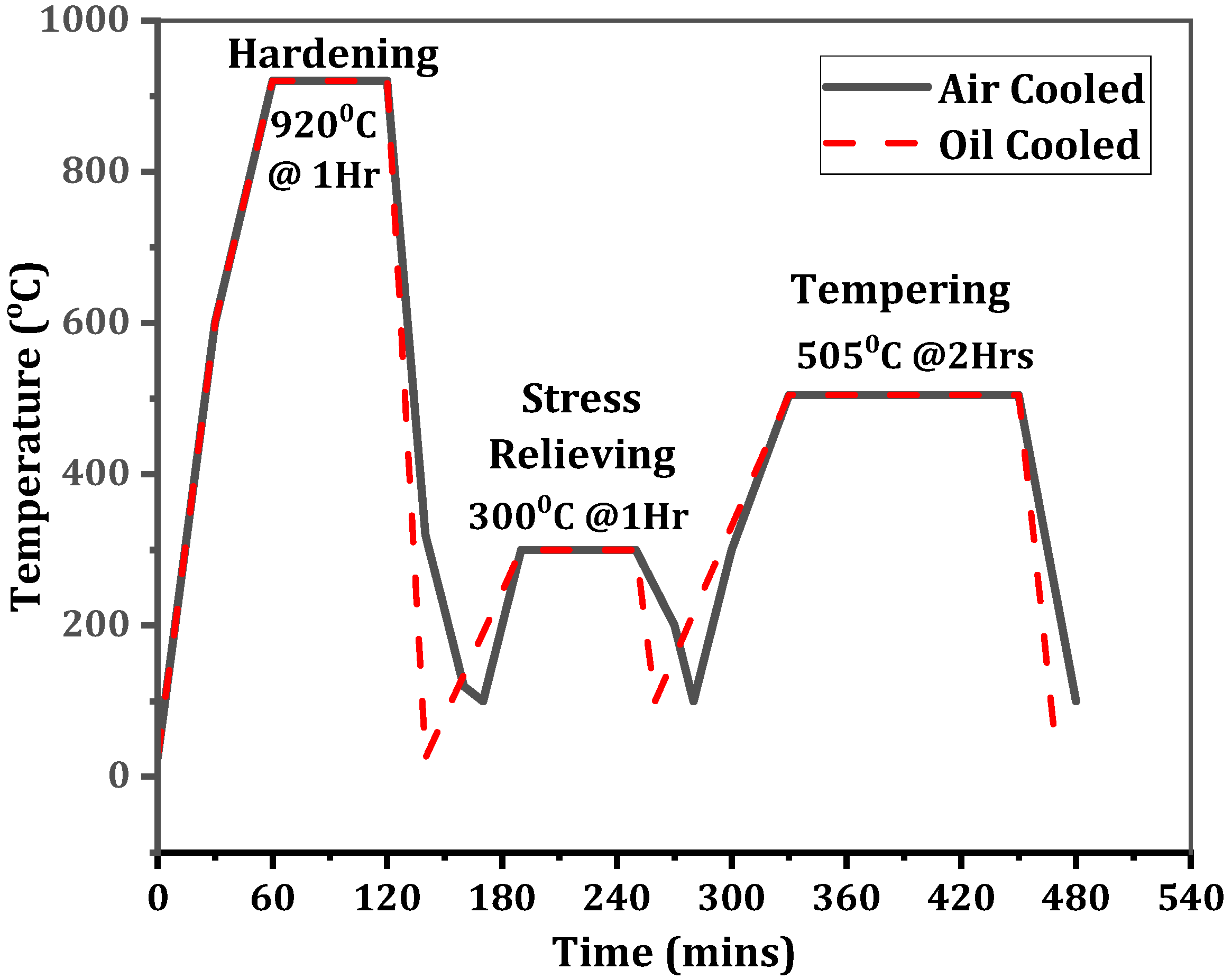
| Hardening | 600 | 920 | 60 | Exp. No.—1, 3, 5 | Exp. No.—2, 4, 6 |
| Stress Relieving | 200 | 300 | 60 | ||
| Tempering | 300 | 505 | 120 | ||
| PWHTCS Conditions | Tensile Properties | Impact Toughness (Joules) | ||||
|---|---|---|---|---|---|---|
| Root Gap (mm) | No. of Passes | UTS (MPa) | 0.2% PS (MPa) | % Elongation (%) | ||
| As-welded | 1 | 2 | 690 | 558 | 16.2 | 27 |
| Air | 1200 | 1075 | 13.5 | 16 | ||
| As-welded | 1.5 | 706 | 509 | 18 | 25 | |
| Oil | 1404 | 1374 | 11.7 | 16 | ||
| As-welded | 2 | 3 | 648 | 459 | 16.3 | 24 |
| Air | 1244 | 1183 | 11.9 | 17 | ||
| As-welded | 1 | 679 | 521 | 17.8 | 34 | |
| Oil | 1417 | 1380 | 9.3 | 17 | ||
| As-welded | 1.5 | 4 | 688 | 439 | 17.7 | 30 |
| Air | 1225 | 1110 | 12.9 | 25 | ||
| As-welded | 2 | 657 | 484 | 16.1 | 52 | |
| Oil | 1301 | 1192 | 11.1 | 20 | ||
Disclaimer/Publisher’s Note: The statements, opinions and data contained in all publications are solely those of the individual author(s) and contributor(s) and not of MDPI and/or the editor(s). MDPI and/or the editor(s) disclaim responsibility for any injury to people or property resulting from any ideas, methods, instructions or products referred to in the content. |
© 2025 by the authors. Licensee MDPI, Basel, Switzerland. This article is an open access article distributed under the terms and conditions of the Creative Commons Attribution (CC BY) license (https://creativecommons.org/licenses/by/4.0/).
Share and Cite
Moinuddin, S.Q.; Khan, M.F.; Alnamasi, K.; Jribi, S.; Radhakrishnan, K.; Hameed, S.S.; Muralidharan, V.; Cheepu, M. Effect of Post-Weld Heat Treatment Cooling Strategies on Microstructure and Mechanical Properties of 0.3 C-Cr-Mo-V Steel Weld Joints Using GTAW Process. Metals 2025, 15, 496. https://doi.org/10.3390/met15050496
Moinuddin SQ, Khan MF, Alnamasi K, Jribi S, Radhakrishnan K, Hameed SS, Muralidharan V, Cheepu M. Effect of Post-Weld Heat Treatment Cooling Strategies on Microstructure and Mechanical Properties of 0.3 C-Cr-Mo-V Steel Weld Joints Using GTAW Process. Metals. 2025; 15(5):496. https://doi.org/10.3390/met15050496
Chicago/Turabian StyleMoinuddin, Syed Quadir, Mohammad Faseeulla Khan, Khaled Alnamasi, Skander Jribi, K. Radhakrishnan, Syed Shaul Hameed, V. Muralidharan, and Muralimohan Cheepu. 2025. "Effect of Post-Weld Heat Treatment Cooling Strategies on Microstructure and Mechanical Properties of 0.3 C-Cr-Mo-V Steel Weld Joints Using GTAW Process" Metals 15, no. 5: 496. https://doi.org/10.3390/met15050496
APA StyleMoinuddin, S. Q., Khan, M. F., Alnamasi, K., Jribi, S., Radhakrishnan, K., Hameed, S. S., Muralidharan, V., & Cheepu, M. (2025). Effect of Post-Weld Heat Treatment Cooling Strategies on Microstructure and Mechanical Properties of 0.3 C-Cr-Mo-V Steel Weld Joints Using GTAW Process. Metals, 15(5), 496. https://doi.org/10.3390/met15050496