Article

Microstructure Tailoring for High Strength Ti-6Al-4V without Alloying Elements through Optimized Preheating and Post-Heating Laser Scanning in Laser Powder Bed Fusion

by
Ahmet Alptug Tanrikulu
1,2,
Aditya Ganesh-Ram
3,
Hamidreza Hekmatjou
3,
Sadman Hafiz Durlov
3,
Md Najmus Salehin
3 and
Amirhesam Amerinatanzi
1,3,*
1
Materials Science and Engineering, The University of Texas at Arlington, Arlington, TX 76019, USA
2
Turkish Aerospace Industries, Ankara 06980, Turkey
3
Mechanical Engineering, The University of Texas at Arlington, Arlington, TX 76019, USA
*
Author to whom correspondence should be addressed.
Metals 2024, 14(6), 629; https://doi.org/10.3390/met14060629
Submission received: 15 April 2024 / Revised: 19 May 2024 / Accepted: 22 May 2024 / Published: 26 May 2024
(This article belongs to the Special Issue Microstructural Tailoring of Metals and Alloys)

Abstract

:
Ti-6Al-4V with its eclectic array of excellent properties along with the combination of meticulous precision and flexibility offered by the laser powder bed fusion (LPBF) technology makes it a strong proponent in the field of engineering applications. As a substantial amount of research has paved the way to fabricate Ti-6AL-4V more effectively and efficiently, researchers are becoming more adventurous in finding out the optimal techniques to get better yields in terms of mechanical responses. This includes post-processing techniques i.e., heat treatment (HT) or introducing various alloying elements. Nevertheless, these techniques not only make the overall fabrication more expensive and time-consuming but also contradict the simplistic notion of additive manufacturing (AM) by imparting multistage fabrication without a considerable improvement overall. Here, we propose an innovative breakthrough in the field of Ti-6AL-4V fabrication with LPBF by introducing an in-situ approach to tackle the handicap mentioned in contemporary studies. By imparting multiple laser scans prior to and after the melting scan at each layer, a remarkable 37% improvement in yield strength (YS) can be achieved with higher elongation, while also maintaining a high relative density of around 99.99%.

1. Introduction

Ti-6Al-4V alloy stands out as the most preferred titanium alloy renowned for its exceptional mechanical properties [1]. Its impressive strength-to-weight ratio, extraordinary fracture toughness, resistance at corrosive environments, and biocompatibility have made it the top choice for manufacturing durable lightweight components needed for the automotive, aerospace, and biomedical industries [2,3]. These exceptional attributes have propelled Ti-6Al-4V to significant prominence for AM applications [2].
AM technology emerged in the 1980s and has seen a surge in interest over the last two decades, particularly among researchers in aerospace engineering, owing to its unique capability to fabricate directly from computer-aided design (CAD) files [4,5]. In aerospace applications, metal AM offers compelling advantages, such as substantial cost and lead-time reduction, mass reduction through highly efficient and lightweight designs, consolidation of multiple components for performance enhancement, and the utilization of novel materials [6]. In addition to these advantages, AM technology enhances sustainability by reducing material waste and minimizing energy consumption [7].
Advanced aerospace components, including impellers, turbine blades, and airfoils, are manufactured using the material Ti-6Al-4V, exploiting the benefits of AM technology [6,8]. LPBF technology is the most adequate fabrication technique among the other metal AM techniques due to its capability to fabricate very fine features which is also termed as the resolution [9]. Utilizing LPBF techniques on Ti-6Al-4V enhances the fine feature details in lightweight engineering components during fabrication, resulting in outstanding mechanical characteristics [10,11,12,13,14].
A high-power laser beam is exposed to micron-level regions interacting with loose powder at very high scanning speeds. This heat source and powder material interaction leads to rapid solidification and cooling rates which deliver highly stressed parts due to the accelerated shrinkage and contraction [15,16,17]. Additionally, heat dissipation through the build material underneath the melt pool promotes directional solidification which turns out as a grain texture in the final microstructure [18,19,20]. The microstructure of the LPBF-fabricated Ti-6Al-4V exhibits an anisotropic mechanical response [21,22,23,24,25].
Despite its capability for complex lightweight geometry fabrication and superior mechanical properties, LPBF-fabricated Ti-6Al-4V has a challenging microstructure that limits the engineering application of this technology and still needs to be fully addressed. There are studies seeking solutions to address these issues through optimization of the process parameters [15,26,27]. In addition to these, there are a great number of reported studies investigating the impact of post-HT [28,29,30,31,32,33]. Due to the requirement for advanced equipment, HT increases the production cost as well as the lead time. To avoid the expense and extra effort to optimize complementary processes for modifying the complex microstructure of LPBF-fabricated Ti-6Al-4V, an innovative in-situ thermal process was proposed in this research.
A combination of preheating and post-heating laser scans, in addition to the melting laser scan, was used to manage rapid cooling during fabrication, leading to a complex microstructure with porosity, micro strain, and variations in α/α′ morphology. The effects of laser parameters during preheating and post-heating were investigated. Compared to the reference specimen condition, which was built with only a single laser scan (melting laser scan only), the porosity level showed a significant improvement. The porosity level of the microstructure built with only the melting laser scan was 0.47 ± 0.015%, consistent with previous publications [34,35]. The proposed innovative scan strategies decreased this value up to 0.01%. During the experiment, first, the effect of the preheating and post-heating laser scan on the microstructure was evaluated independently and the findings indicated that the microstructure exhibited the lowest porosity level when the additional energy was limited within the range of 25 J/mm3 to 45 J/mm3, regardless of the sequence of the additional scan applied before or after the melting laser scan. Then the combination of both preheating and post-heating laser scan strategy at each layer was studied.
The objective of this study is to modify the microstructure of LPBF-fabricated Ti-6Al-4V, which initially exhibits relatively low mechanical strength due to inherent porosity, micro strain in the crystal structure, and grain morphology. This is achieved by utilizing the laser source with multi-laser scan strategies before and after the melting scan. The average reported YS of the literature for LPBF-fabricated Ti-6Al-4V was 1048.9 ± 120 MPa [28].
The common strengthening practice in materials processing applications has been studied by introducing alloying elements and components (N2 [36], LaB6 [37], TiC [38]) to the microstructure during LPBF fabrication. The results of this study indicate that the investigated innovative in-situ thermal process modifies the LPBF-fabricated Ti-6Al-4V microstructure and delivers very high mechanical strength with up to 37% YS compared to the as-built condition without alloying elements or compounds. Additionally, a significant increase in elongation was observed, up to 59% compared to the elongation at the reference (as-built) condition. This reduction is minimal compared to the reductions reported in existing strengthening methods in the literature [37,39,40]. It is worth noting that the reported findings in material properties were achieved during the fabrication process, requiring no additional post-processing or complex process modification to achieve these remarkable properties.

2. Materials and Methods

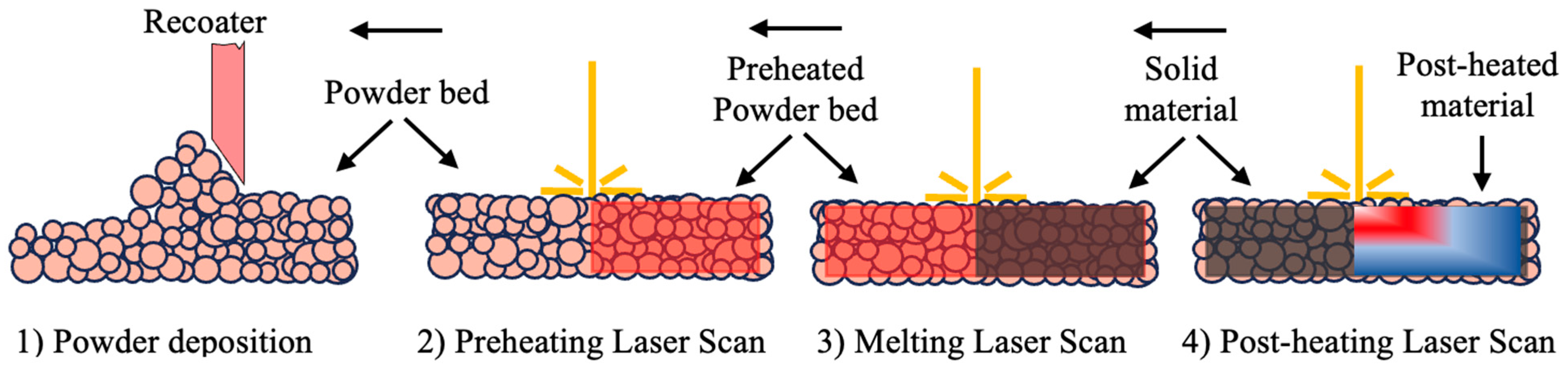
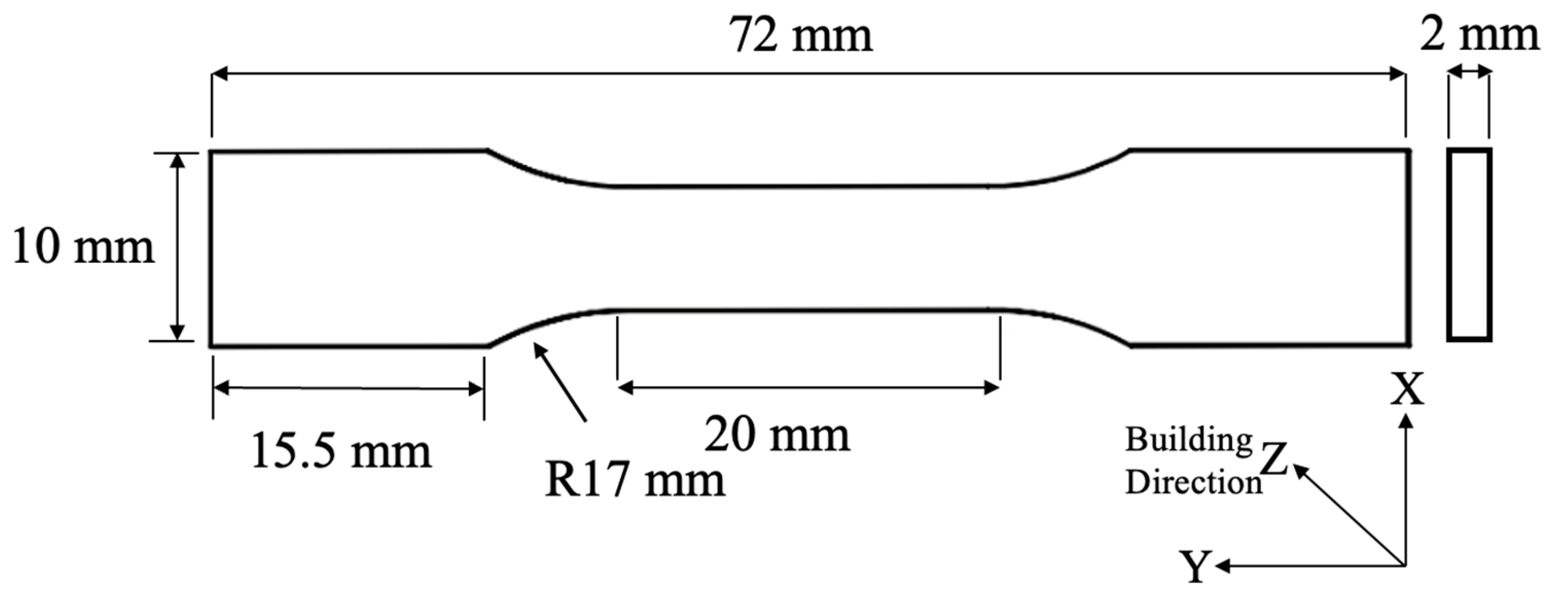
2.1. Materials and Fabrication

The metal powder used in the experimental study was provided by EOS North America (Pflugerville, TX, USA). The powder material is fabricated by gas atomization to achieve the highest spheroidization quality. The composition of the materials has (%wt.) 5.50–6.75 Al, 3.50–4.50 V, 0.20 O, 0.05 N, 0.08 C, 0.015 H, 0.30 Fe, and the balance was Ti [41] and standardized as Ti-6Al-4V Grade 5.
A 3D printer, EOS M290 (EOS GmbH, Electro Optical Systems, Krailling, Germany) equipped with Ytterbium fiber laser power of 400 W was utilized for the fabrication of the samples. Fabrication parameters of Ti-6Al-4V by the manufacturer are 280 W laser power, 1300 mm/s scan speed, 120 μm hatch spacing, 100 μm laser spot size with a Gaussian distribution of energy, and 40 μm of layer thickness with 47° angle stripes scanning strategy (used for the reference specimen process parameters) [27]. These parameters were obscured by the printer’s proprietary software, EOS Print (version 2.6; EOS GmbH, Krailling, Germany). Specimens were exposed to an initial preheating laser scan with varying laser power and laser scan speed. This was followed by the melting laser scan which was conducted under the manufacturer’s recommended parameters. Finally, a post-heating laser scan was applied once more, with a variety of laser power and laser scan speeds. The illustrated laser scanning strategy sequence is presented in Figure 1. To quantize the effect of the applied preheating and post-heating scan along the melting laser scan, energy density was calculated from the equation reported by Thijs et al. (Equation (1)) [42].
E v = P v · h · t

2.2. Experimental Methods

Microstructure samples fabricated with the dimensions of 20 mm × 6 mm × 6 mm and test coupons for tensile testing fabricated in dog-bone geometry with the dimensions shown in Figure 2. The most inclusive tensile test methodology, ASTM E8/E8M, does not have rectangular cross-section test specimen dimensions smaller than 25 mm gauge length. Therefore, the authors created a representative geometry close to that dimension, which is suitable for fitting multiple specimens in one fabrication batch for an LPBF printer.
Box—Behnken design of experiment (DOE) [43] was performed with 4 factors at 3 levels each to explore the optimal process parameters for the fabrication. The findings of the previous study revealed that the best porosity values were obtained when the additional energy input was kept in the range of 25 J/mm3 to 45 J/mm3 [44]. The results of the Box–Behnken DOE show the fabrication scenarios including those with a higher total energy of 45 J/mm3 which was set as the limit for the additional energy input. Table 1 presents a compilation of potential combinations of preheating and post-heating energy derived from the Box-Behnken design, with the total energy kept below 45 J/mm3.
Scanning Electron Microscopy (SEM) was performed for porosity, α-phase lath width, and grain morphology caused by various energy inputs during the in-situ thermal process. Microstructure imaging samples were cut out by a TECHCUT 5TM precision cutter (Allied High-Tech Products, Inc., Rancho Dominguez, CA, USA) from the center of the fabricated specimen along the building plane. Samples were cold mounted for the sample holder of the automated polishing equipment (E-PREP Grinding/Polishing System, Allied High-Tech Products, Inc., Rancho Dominguez, CA, USA). Sample preparation for the metallography started with the grinding from 320 to 1200 grit size of SiC sandpaper. It was then followed by the first step of polishing on a DiaMat® polishing cloth (Allied High-Tech Products, Inc., Rancho Domingues, CA, USA) with 1 μm diamond suspension. The final step of the polishing was performed with 0.04 μm colloidal silica suspension on Red Final C® polishing pad used to obtain scratch-free, mirror-like finish sample surfaces. Polished samples were rinsed in micro-organic soap and cleaned with isopropyl alcohol. Samples were etched with Kroll’s reagent (1–3 mL HF, 2–6 mL HNO3, 100 mL water) to identify the grain boundaries and phases of the microstructure.
The porosity level of each microstructure sample was assessed by utilizing the image processing software Image J (version 1.53) [45]. The porosity distribution was determined from at least three different regions at 2 magnification levels (500× and 1000×). Image J was also used for the lath width calculation of the α-phase. For lath thickness measurement, microstructure images were first converted to RGB stack-type grayscale images before setting the auto contrast level. Thresholding was applied to improve the contrast of α/α′ phase laths borders. Particle sizes within the range of 0.2 μm to 2.0 μm were analyzed, and the total counts for each size were computed to obtain the average value. This was performed on a minimum of 6 different images to obtain statistically reliable data for each sample.
X-ray diffraction (XRD) analyses were conducted for further microstructural characterization, to calculate lattice parameters, and to determine microstructure orientations for each sample. A Bruker D8 Advance X-ray diffractometer (Bruker Corporation, Madison, WI, USA) was utilized for the XRD with a Cu k-alpha wavelength of 1.5406 Å, operating at 40 mA current and 40 kV voltage at room temperature. Measurements were taken with step intervals of 0.05° and a scan speed of 1 s/step, while 2θ ranged from 20° to 80°.
Lattice parameters were computed following Bragg’s law (Equation (2)), where d represents inter-planar spacing, and a and c denote the lattice parameters. The variables h, k, and l refer to the Miller indices.
1 d 2 = 4 3   ( h 2 + hk +   k 2 a 2   ) + l 2 c 2 λ = 2 d   sin θ
XRD data was analyzed with the Williamson–Hall (W–H) model [46] to obtain the micro strain value of the reference and the in-situ thermal processed samples. The XRD data was utilized in the following equations (Equations (3)–(5)). The XRD pattern’s peak broadening results from crystal imperfections and distortion, as expressed by ε ≈ βs/tanθ. The plot of the W–H model was used for the calculation of the micro strain value. Si standard reflection (0.0013 rad) [47] was subtracted before strain analysis using the W–H method. The Scherrer’s equation is expressed as Equation (3) and further derived to Equation (5) where β is peak broadening, λ is the wavelength (Å), K is the Cu Ks (0.94), D is the crystallite size (nm) and θ is the peak position.
D = λ   K β   cos θ
β = β T 2 β i 2
β   cos θ = λ   K D + 4 ε   sin θ
Mechanical testing was performed using a Shimadzu EHF E-Series (100 kN) testing machine equipped with a 4830 Servo Controller (Shimadzu Scientific Instruments, Inc., Missouri City, TX, USA). For accurate strain measurements in the gauge section, a digital image correlation (DIC) system (Correlated Solutions, Inc., Irmo, SC, USA) was employed. The system tracked light-intensity patterns of high-contrast speckles on the coupon surface to measure the surface displacements and strain. Image capturing utilized a charged-coupled device (CCD) camera with 2.3 Mega Pixels each, specifically a Grasshopper GS3-U3-23S6M (FLIR Systems, Inc., Santa Barbara, CA, USA), featuring a pixel array of 1920 × 1200. Image and data processing were carried out using VIC-3D-9® software (Correlated Solutions, Inc., Irmo, SC, USA). All specimens underwent testing at a constant loading rate of 1.2 mm/min, following the recommended testing standard for LPBF-fabricated Ti-6Al-4V tensile specimens as outlined in the literature [48].

3. Results

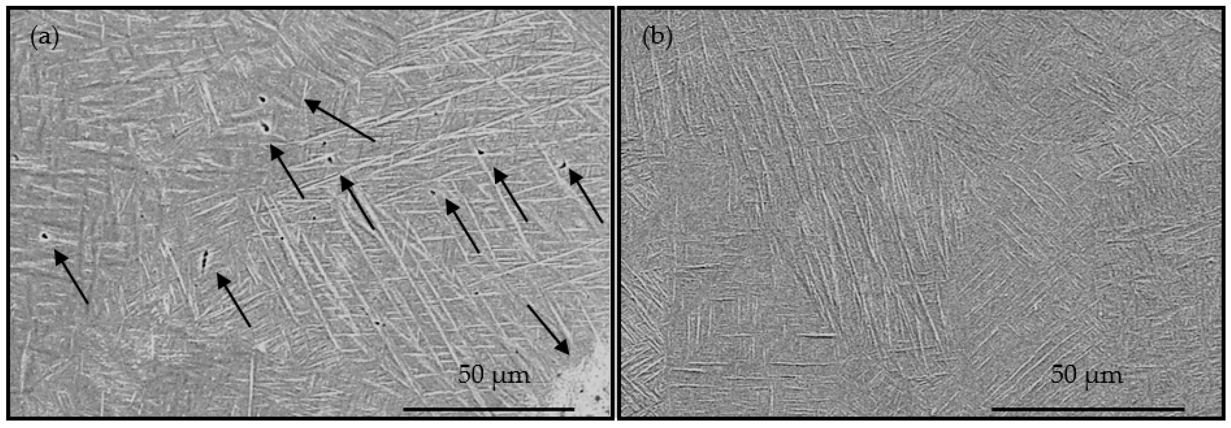
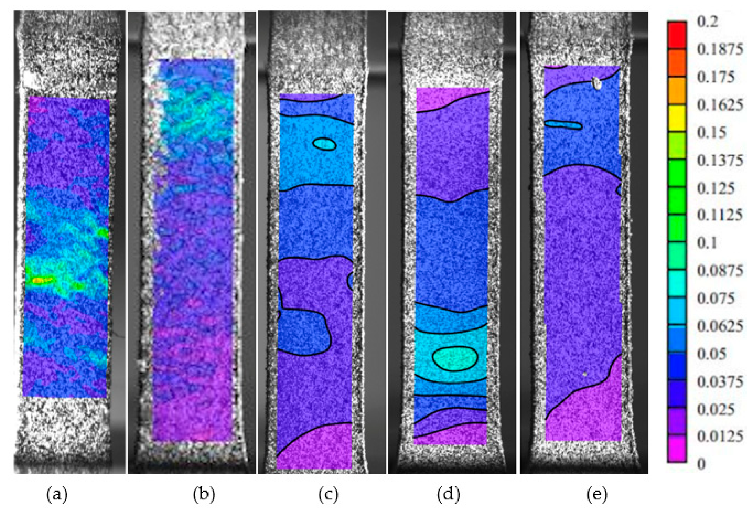
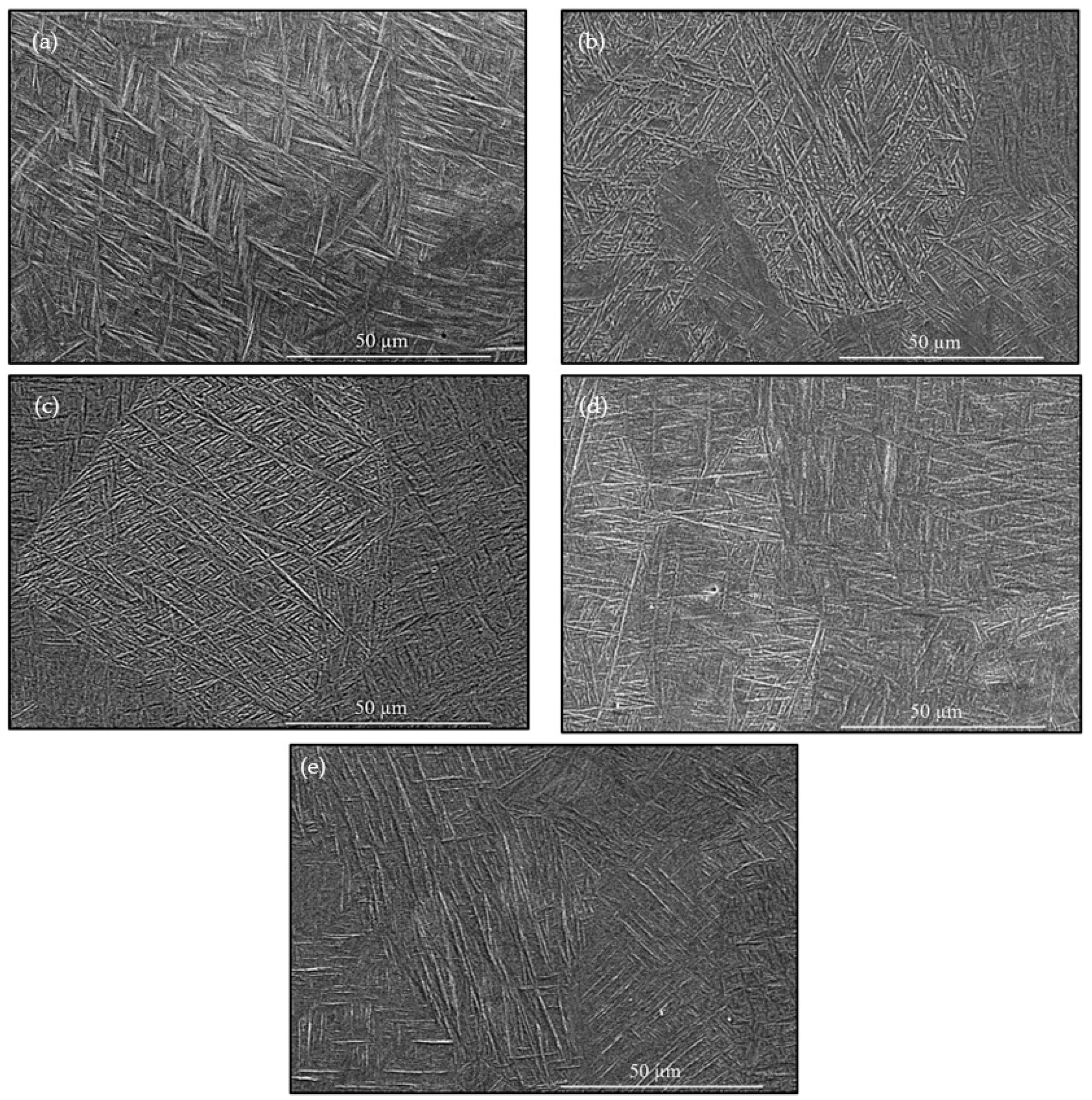
3.1. Microstructure Defects and Grain Structure

SEM microstructure images of the reference sample and one of the in-situ thermally processed samples (196W preheating laser scan power, 1950 mm/s preheating laser scan speed + 56 W post-heating laser scan power, 1300 mm/s post-heating laser scan speed) are depicted in Figure 3. In Figure 3a the internal defects of the reference sample were marked with black arrows. Figure 3b shows the obvious effect of the in-situ thermal processing on the inherent process-induced defects of the LPBF-fabricated Ti-6Al-V. Nevertheless, while defects are easily discernible in the reference sample micrograph, no distinct defects were observed in the in-situ thermally processed sample. To avoid any potential confusion in the further sections of this paper, it is better to clarify that all volumetric defects identified through the SEM micrography are counted and termed as porosity and are included during the defect calculations regardless of the shape and size of the discontinuity.
Porosity levels for the preheating laser scan and post-heating laser scan applications were assessed by SEM micrographs. Figure 4 shows the porosity level of the preheating and post-heating applications respectively. It was observed that in both applications the lowest porosity level was achieved in the energy density range of 25 J/mm3 to 45 J/mm3.
In the presented in-situ thermal process, which involves the combination of preheating and post-heating laser scans, the total energy level was maintained within this range. The Box—Behnken DOE parameters are listed in Table 2 for the selected preheating and post-heating laser scan parameters. The potential combinations of process parameters were analyzed, and parameter sets falling outside of this energy range were eliminated. All process parameters set combinations with a total energy input between 25 J/mm3 and 45 J/mm3 were derived from the remaining dataset for the fabrication process and are listed in Table 1.
Microstructure coupons were fabricated for each parameter set listed in Table 1 and the porosity levels of the microstructure for each case are listed in Table 2.
Figure 5 illustrates how the porosity value responds to variations in the applied preheating laser scan parameters during the in-situ thermal processing of the LPBF-fabricated Ti-6Al4V. A notable decrease in porosity was observed at lower energy levels of the preheating laser scan when combined with each post-heating laser scan. Specifically, preheating laser scan speeds below 1000 mm/s and laser power less than 180 W led to higher porosity levels when they were coupled with the post-heating laser scan. It was noted that samples incorporating post-heating at a laser power of 56 W and 1300 mm/s exhibited increased sensitivity to porosity formation. The samples subjected to post-heating with a laser scan power of 56 W and a scan speed of 650 mm/s exhibit the least variation in porosity depending on the preheating process parameters.
The reference coupon did not undergo any preheating or post-heating and exhibited an average porosity of 0.47% ± 0.015%. It is noteworthy that the porosity level was reduced to 0.01% ± 0.01% with the applied in-situ thermal process presented in this research. The combination of preheating and post-heating laser scans achieved the four lowest porosity levels and were selected for further microstructural characterization and mechanical testing for the following sections of this publication. These parameter combinations are listed in Table 2, under row numbers 3, 10, 19, and 23.
Examination of the microstructure through SEM micrography revealed that LPBF-fabricated Ti-6Al-4V possessed lamellar microstructure that lath colonies correspond to in either the α or α′ phase [49]. The lath thickness (in some studies it is referred to as lath width) of the basketweave-like structure determines the mechanical response of the material [50]. The lath thickness of the samples that were exposed to the in-situ thermal process and the reference sample (no thermal processing) is presented in Figure 6 using image processing techniques on SEM micrographs via ImageJ software.
In the reference sample with the energy input of 44.87 J/mm3, the α/α’ laths thickness was measured to be 0.797 ± 0.005 µm. Similar to the reference sample, the in-situ thermally processed samples exhibited α/α’ laths thickness ranging from 0.792 µm to 0.812 µm at the total energy inputs between 74.79 J/mm3 and 89.74 J/mm3. The α/α’ lath thickness measurements were conducted as explained in the previous section and the authors quantized at least 6 images at two different magnification levels each to maintain the reliability of the quantized data.

3.2. Lattice Transformation, and Phase Decomposition in Preheated LPBF Ti-6Al-4V

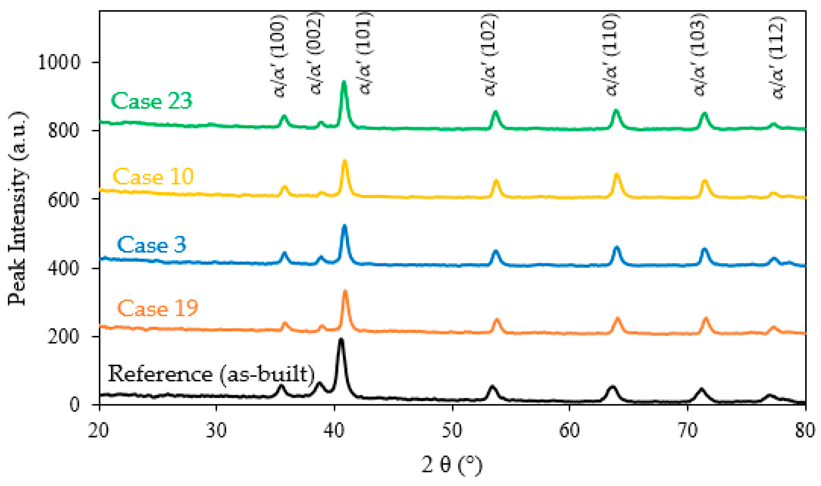
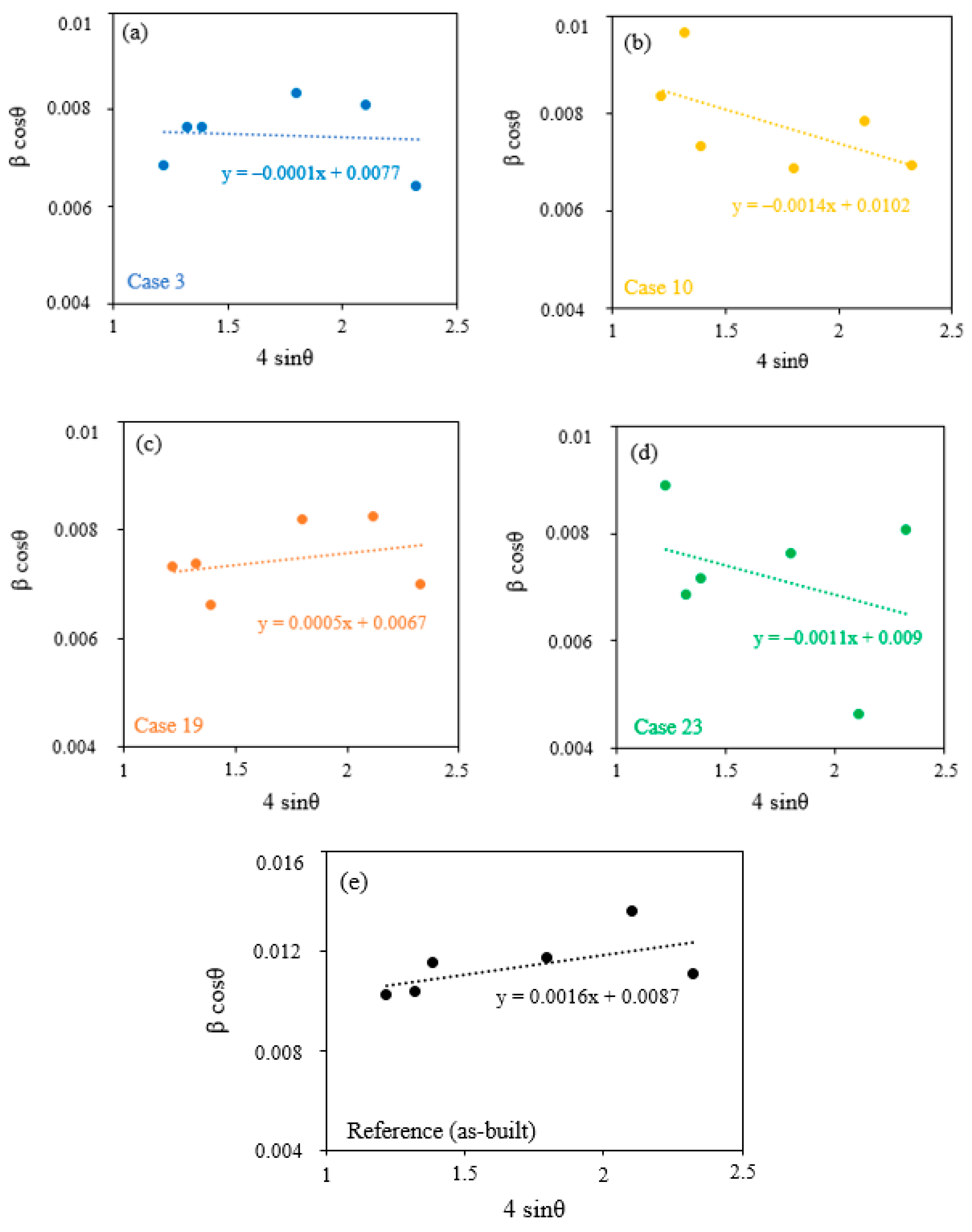
3.2.1. Crystallography through XRD Analysis

Figure 7 shows the XRD profiles of the reference and in-situ thermally processed samples, arranged in ascending order of total energy inputs. The highest intensity of Bragg’s peak was observed at the (101) plane for the reference sample. In parallel, in-situ thermally processed samples have similar peak patterns; it is noteworthy that the strongest peak intensity was observed at the (101) plane. The XRD diffraction pattern data was quantized by utilizing Bragg’s and the W–H model for further evaluation in the following sections.
The W–H model was performed to determine the impact of the in-situ thermal process on the micro strain values for the selected cases that delivered the lowest porosity levels. The W–H model for the reference sample and the in-situ thermally processed samples are illustrated in Figure 8. When the W–H equation (Equation (5)) is viewed as a linear equation in the form of y = mx + c, then the slope of the equation corresponds to the strain value. The reference sample exhibits a positive slope. It is noteworthy that utilizing the in-situ thermal processing transformed the slope from positive to negative except for one in-situ thermal process condition (Figure 8). However, the in-situ thermal processing with the parameters of 252 W preheating laser scan power, 1950 mm/s preheating laser scan speed, 56 W post-heating laser scan power, and 650 mm/s post-heating laser scan speed (Figure 8c) exhibits a different trend in which the slope is positive, but the value is smaller than the reference microstructure. The transformation of the slope from a positive value to a negative value shows that the micro strain value shifted from tension mode to compression mode. Additionally, the change of the slope to a smaller positive value shows the decrease in the strain in the tension mode.

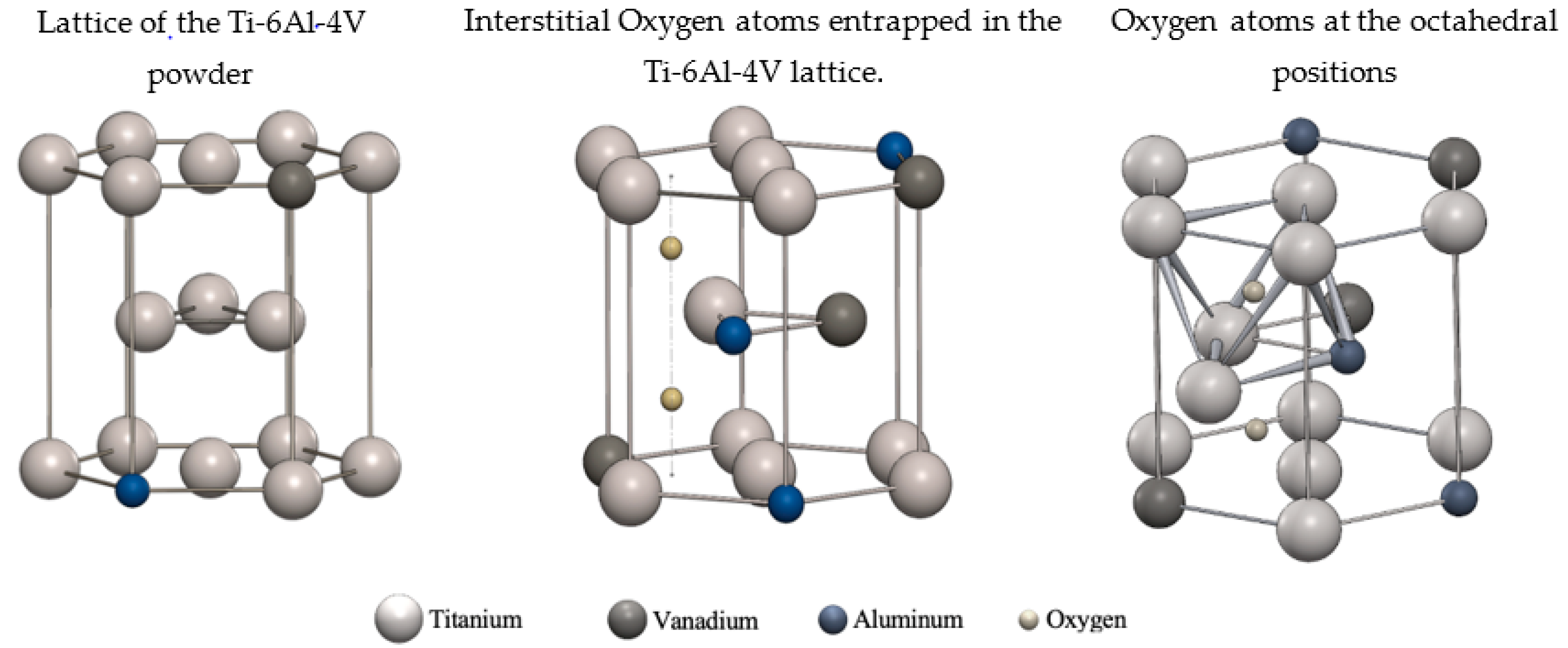
3.2.2. Hexagonal Close-Packed (HCP) Lattice Modification

The XRD data utilized in Bragg’s model (Equation (2)) for additional microstructure characterization particularly focus on lattice deformation in the material [15]. As per the model, Figure 9 depicts the lattice parameters of the HCP phase, which is the prevailing stable phase indicated by the XRD data [44] with additional energy to the system; a reduction of 1.1% and 0.3% in both lattice parameters of a and c was observed, respectively (Figure 9a,b). Furthermore, lattice strain was observed with the applied in-situ thermal process (Figure 9c). The lattice strain was shown with a higher c/a ratio. The in-situ thermally processed samples exhibit lower ‘a’ and ‘c’ lattice parameters. However, the ratio of the parameters in the modified microstructure indicates a higher strain value.

3.3. Mechanical Properties

The mechanical behavior of the modified microstructure with the in-situ thermal process was quantized through the tensile test. The stress–strain plot is depicted in Figure 10. It is evident that the application of the in-situ thermal process had a noticeable effect on the material’s strength. It was observed that both the Ultimate Tensile Strength (UTS) and the Yield Strength (YS) values were enhanced. A remarkable increase in the slope during elastic deformation achieved a higher YS for each in-situ thermally processed specimen. The reference specimen (as-built) exhibits a 1012.8 MPa YS and 1187.1 MPa UTS. The mechanical strength of the as-built microstructure is matching with the literature with a slightly lower YS [51]. The improvements in the YS for the four selected in-situ thermal process conditions were 37%, 33%, 15%, and 31% for sample numbers 3, 10, 19, and 23 respectively, as listed in Figure 10. The enhancements in UTS were measured as 28%, 23%, 8%, and 45% for case numbers 3, 10, 19, and 23, respectively. The process parameters of case 3 (preheated with 252 W laser power, 1625 mm/s laser scan speed, and post-heated with 56 W laser power, and 975 mm/s laser scan speed) exhibit the highest UTS (1515.6 MPa) and YS (1389.0 MPa) which is about a 28% and 37% improvement relatively compared to the reference case. The lowest improvement in the material’s strength was observed in case 19 with the in-situ thermal process conditions of 252 W preheating laser power, 1950 mm/s preheating laser scan speed, 56 W post-heating laser power, and 650 mm/s post-heating laser scan speed. The measured UTS and YS were 1284.3 MPa and 1061.9 MPa, with an improvement of 15% and 8%, respectively.
The localized strain right before the rupture for the reference and the in-situ thermally processed specimens are depicted in Figure 11. It was observed that the reference sample (Figure 11) has the highest deformation amount and the largest deformed region compared to the in-situ thermally processed specimens. Among the in-situ thermal applications, it is noteworthy that case 23 has the lowest deformation region (cyan regions).

4. Discussions

4.1. Material Modification via In-Situ Thermal Process toward a Defect-Free Microstructure

In the present study, an in-situ thermal process to tailor the microstructure of Ti-6Al-4V during the LPBF fabrication was investigated. The application of the preheating laser scan before the melting scan to modify the microstructure was investigated in detail in the previous study [44,52,53,54]. A novel third laser scan strategy was introduced in the proposed approach to gain further precision in the microstructure modification. This complimentary third scan has been termed as the post-heating laser scan. The innovative in-situ thermal processing developed for the LPBF process and Ti-6Al-4V material aims to control rapid cooling rates. Higher energy input regulates the rapid cooling and also effects the directional solidification of the PBF technology [44]. The interaction of the laser source with the loose titanium powder creates a melt pool that has powder borders. The laser power and the scanning speed influence the melt pool size (width and depth); higher laser power can lead to a higher energy input, influencing grain growth and phase transformation kinetics. A faster scanning speed can generate a narrower melt pool with a faster cooling rate which consequently affects the wetting surface energy of the melt pool at the borders. This partial melting enhances the volumetric defects inside the material and decreases the surface finish quality at the surface of the part. Faster scanning speeds result in shorter exposure, which can lead to a finer microstructure due to the faster cooling rate. The proposed thermal processing enhances melt pool characteristics to prevent process-induced volumetric defects, transforms the micro strain characteristics of the crystal structure to minimize the effect of the inherent residual stress, and partially refines the grain morphology to strengthen the material’s mechanical response. It is noteworthy that the modified microstructure with the in-situ thermal processing led to a significant reduction in the process-induced porosity level of the microstructure. Almost 98% improvement was observed by performing the in-situ thermal process at the porosity level. This improvement can be considered as a result of partial melting [55] during the preheating laser scan and re-melting [26] with the complementary post-heating laser scan. Low energy inputs cause partial melting [56]. At this stage, the applied preheating can be considered as the low energy input that causes powder particles to partially melt at their connection regions, leading to a sintering-like effect. The agglomerated powder particles with irregular geometries in the powder bed impede the powder particle spattering during the melting. Spattering due to the high-speed laser and loose powder interactions is one of the reasons for the inherent porosity [57] in LPBF technology. Similar improvements were observed in the literature and achieved by the re-melting effect [15,26,58]. Post-heating laser scan in the in-situ thermal process can be considered as the remelting effect. However, the post-heating laser scan has a lower energy value than the melting scan, and the material has elevated temperatures in which even lower energy inputs might exceed the melting temperature of the material. Furthermore, Figure 5e illustrates that elevated post-heating laser power corresponds to a relatively higher level of porosity, attributed to increased evaporation under higher post-heating energy.
The results plotted in Figure 5e demonstrate that lower post-heating laser scan energy delivered a lower porosity value compared to the higher energy levels. The results indicate that the in-situ thermal process enhanced the soundness of the material at moderate preheating laser scan energies and lower post-heating laser scan energy levels. The inherent volumetric defects decreased from 0.47% (as built) to 0.01%. It is reported that the complementary post-process of HIP [17,59] also reduces the porosity level drastically; however, it requires additional processing cost and time. The proposed in-situ thermal microstructure tailoring promises to eliminate the requirement of additional complementary processes to reduce the inherent volumetric defects of the LPBF-fabricated Ti-6Al-4V. Although there are some studies that evaluate the multi-laser scan effect on Ti-6Al-4V materials during LPBF, the effect of the energy at different scanning steps remains unsolved. In the presented study, robust control of the multi-scan laser scan promises precise final microstructure adjustments, rather than the existing literature, which is limited to the multi-scan laser application of the single laser parameters to obtain the remelting effect. Moreover, in the presented study, an improvement in the inherent porosity level was achieved without the necessity of costly and time-consuming additional processes such as HIP.

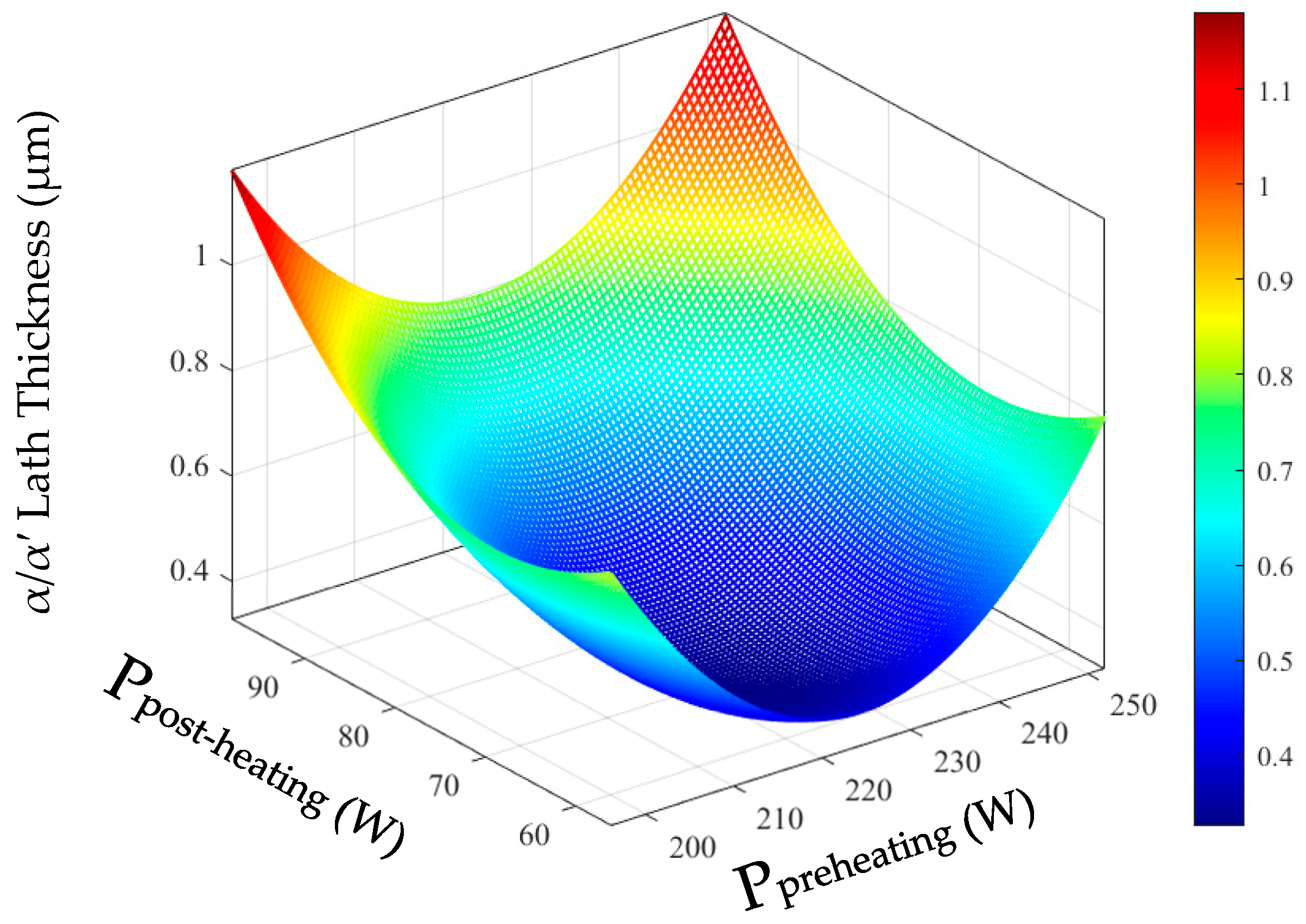
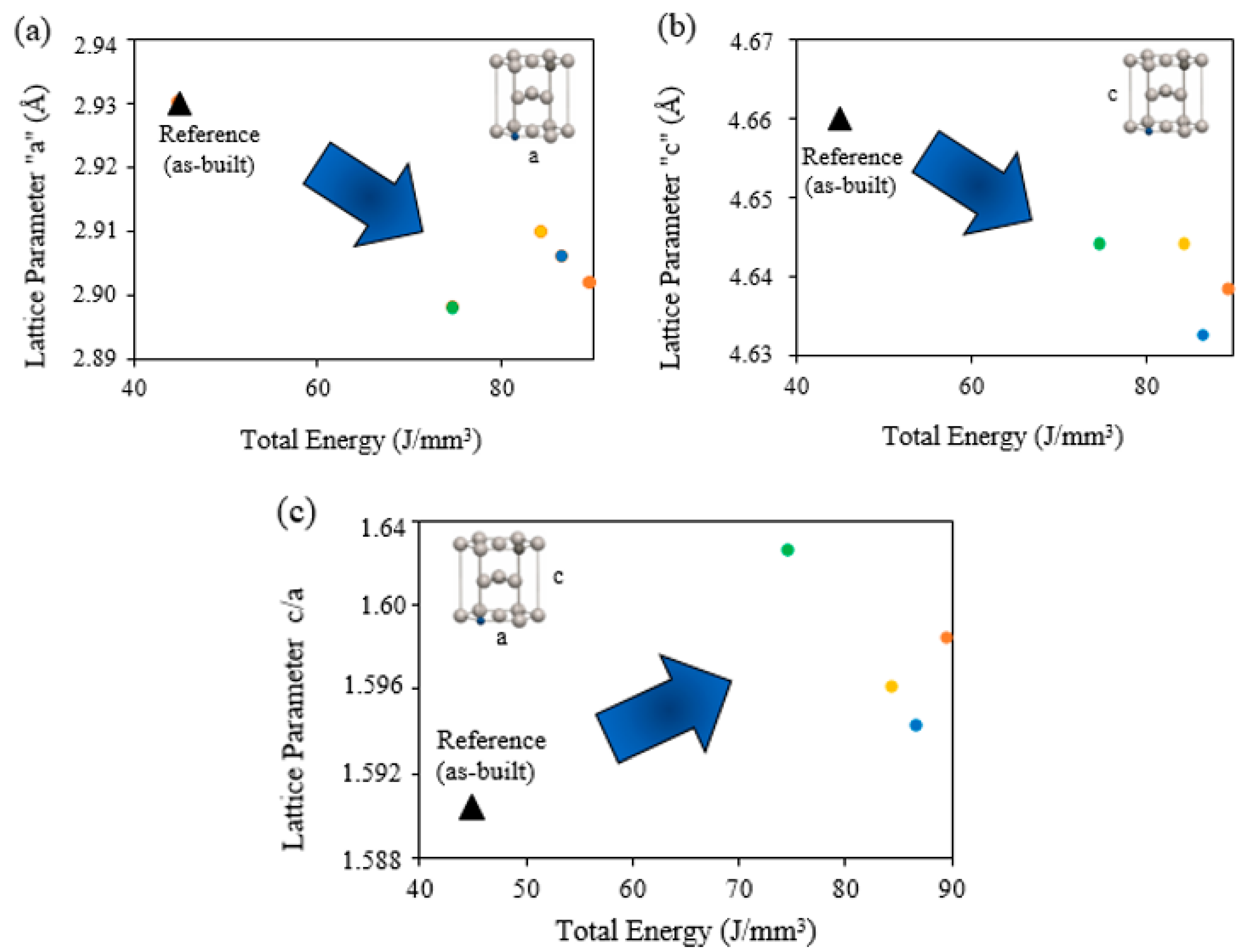
4.2. Modification of the α/α′ Lath Growth and The HCP Lattice Strain during β → α + β Decomposition

The microstructure of LPBF-fabricated Ti-6Al-4V primarily consisted of α and α′ phases. In the present study, both phases were referred to as the structure of α/α′ phases, in consideration of the complexity of the microstructure and the common literature practice. The mechanical response of the microstructure is a result of these α/α′ phases’ lath structures [60]. The main structural feature of these phases that defines the mechanical property of the material is the lath thickness. The formulated innovative in-situ thermal processing of Ti-6Al-4V during LPBF transformed the α/α′ lath structure during the β → α + β decomposition into a slightly thicker morphology regarding the total heat input. Figure 6 demonstrates the variation of the α/α′ phases’ lath thickness in relation to the total energy input during the fabrication process. The thickness variation after the in-situ thermal processing changed the initial thickness of the α/α′ phases from 0.797 µm to a thickness variation of 0.792 µm to 0.812 µm (Figure 12). However, the laths shifted to a thicker structure naturally due to the regulated cooling rate, and a thinner lath morphology compared to the reference condition was also observed [61]. This divergence of the lath structure can be correlated with the prior-β grain structure. It is known that the parent β grains exhibit different sizes and shapes during grain growth under different cooling rates from melting to the allotropic transformation temperature [62]. The slower cooling rates with applied preheating modifies the parent grain morphology to a lower surface geometry [44]. The prior-β boundaries transformed from random polygonal to tetragonal and circular at further preheating heat inputs [44]. Similarly, the regulated cooling rate of the proposed in-situ thermal tailoring of the Ti-6Al-4V microstructure modified the parent β alternatively regarding the total heat input and the sequence of each energy levels. Thus, the decomposition of the α/α′ laths from the parent β grain was affected by the parent β grain geometry and resulted in a variety of lath structure in terms of thickness. The measured lath thickness values in Figure 6 and the micrographs from Figure 12 make it challenging to establish a clear trend relation between the α/α′ lath thickness and the in-situ thermal process of LPBF-fabricated Ti-6Al-4V. Therefore, it is rational to relate the mechanical response more to the enhanced porosity and micro strain condition of the microstructure.
Moreover, XRD analysis pronounced a transformation in the peak pattern of the material. Microstructure characterization was performed through XRD analysis to provide detailed insights into the impact of the in-situ thermal processing on the LPBF-fabricated microstructure, specifically on the material’s lattice structure. Figure 7 exhibits the peak patterns of the reference specimen and the selected in-situ thermally processed specimens. A noteworthy reduction in the disparity between the peak intensity values was observed. This can be considered as an improvement in the isotropy of grain orientation within the microstructure, which is associated with the cooling rates and the inherent directional cooling behavior of the process. Introducing additional energy during the in-situ thermal processing changed the cooling rate of the material which turned out as a transformation in the peak patterns. Additional introduced energy increased the total energy input which decreased the cooling rate. This observation is in parallel with the previous studies that reported the XRD diffraction patterns of the conventionally fabricated Ti-6Al-4V with slower cooling rates [63,64]. The change in the grain orientation will transform the deformation behavior of the material under tensile loadings. Deformation is governed by the grain boundary network during the elastic region [65] and once it exceeds to the plastic region, it is driven by the active slip systems of the microstructure [66]. Change in the grain orientation highly affects the deformation mechanism in the elastic region as discussed in the subsequent paragraphs in this section [44].
XRD diffraction patterns were also employed to calculate the lattice parameters by Bragg’s law. Figure 9 illustrates the lattice parameters of the reference specimens and in-situ thermally processed specimens. Figure 9a,b pronounced a noteworthy reduction in both lattice parameters of ‘a’ and ‘c’ after the application of the additional energy compared to the reference specimen. The HCP lattice parameters changed from the initial condition, and a notable strain was observed. The strained HCP lattice structure of the in-situ thermal process is shown in Figure 9c. The observed lattice strain due to the additional heat input to the powder with a preheating laser scan is in parallel with the previous study [44]. The lattice distortion is recognized to have a direct influence on the dislocation density and mobility, ultimately impacting the mechanical strength of the material [67]. The lattice deformation of the Ti-6Al-4V material can be rationalized with the super-saturated lattice with substitutional V atoms and interstitial O atoms. Additional energy during the in-situ thermal process modified the rapid cooling rates of the LPBF process. It is noteworthy that the lowest additional energy during the in-situ thermal process, case 23, exhibits the highest lattice distortion among all in-situ thermal process cases. The lower heat input is considered as the faster cooling rate which rationalizes smaller HCP lattices with limited vanadium diffusion. Vanadium atoms occupied the titanium atom positions with smaller radii. The lattice strain along the c-axis can be rationalized with the oxygen entrapment of the Ti-6Al-4V material at elevated temperatures. However, in the material fabricated under the shield gas of argon, there remains a limited amount of oxygen in the chamber, reaching up to 0.2%. Titanium is known for its high affinity to oxygen among metallic materials [68] which makes the material sensitive at elevated temperatures even at very low oxygen concentrations. Schematic of the lattice transformation is depicted in Figure 13.

4.3. The Mechanical Response of the Tailored Microstructure

Mechanical testing was performed to evaluate the response of the modified microstructure by the in-situ thermal process proposed in the presented research. A remarkable improvement in the strength value was observed with the application of the preheating and post-heating laser scans. It is demonstrated in Figure 10 how the in-situ thermal process enhances the materials strength of LPBF-fabricated Ti-6Al-4V. The most significant enhancement in strength was noticed with the in-situ thermal process parameters of case 3 (252 W preheating laser power, 1625 mm/s preheating laser scan speed, 56 W post-heating laser power, and 975 mm/s post-heating laser scan speed (illustrated by the blue line in Figure 10)). This fabrication case had the lowest energy input among the other in-situ thermally processed specimens. This remarkable improvement was attributed to the modified microstructure which exhibited one of the lowest porosity values (Figure 3 and Figure 5d) and the lattice strain value (Figure 9c). The negative effect of internal defects on mechanical properties is a well-known aspect [69,70,71] especially on the elastic modulus of the material, which is an outcome of the chemical composition and the crystal structure [71]. Bandyopadhyay et al. [71] reported a drastic change in the elastic modulus with respect to the relative density of the Ti-6Al-4V. According to their study, a slight decrease in relative density of around 5% (from 75% to 70%) decreased the modulus by around 50% (from 20 GPa to 10 GPa). The authors observed a similar trend in the presented study: with a decrease in porosity, the elastic modulus of the LPBF-fabricated Ti-6Al-4V increased (8%) (Figure 10). The greater influence of lower porosity on the elastic modulus was attributed to the combined effect of other microstructural features of the crystal structure of the material, particularly, micro strain and the lattice distortion. This finding is reported for the first time in the literature.
It is rational to obtain a reduction in elongation following the material’s strengthening [72]. The presented in-situ thermal process exhibits very high strength values with an increase in the elongation value of the material. A reduction in the porosity level can cause this microstructure response, leading to higher elongation [73]. The results of the presented study demonstrate that the innovative in-situ thermal process applied to LPBF-fabricated Ti-6Al-4V enhances the strength by up to 37% while eliminating the reduction of the elongation which is a result of the innovative strengthening process.

5. Conclusions

In the present study, an in-situ microstructure tailoring process is proposed by optimizing the layer wise preheating and post-heating laser scans. The triple laser scan strategy during LPBF fabrication of Ti-6Al-4V material modified the microstructure which turned out as a superior mechanical response of the material.
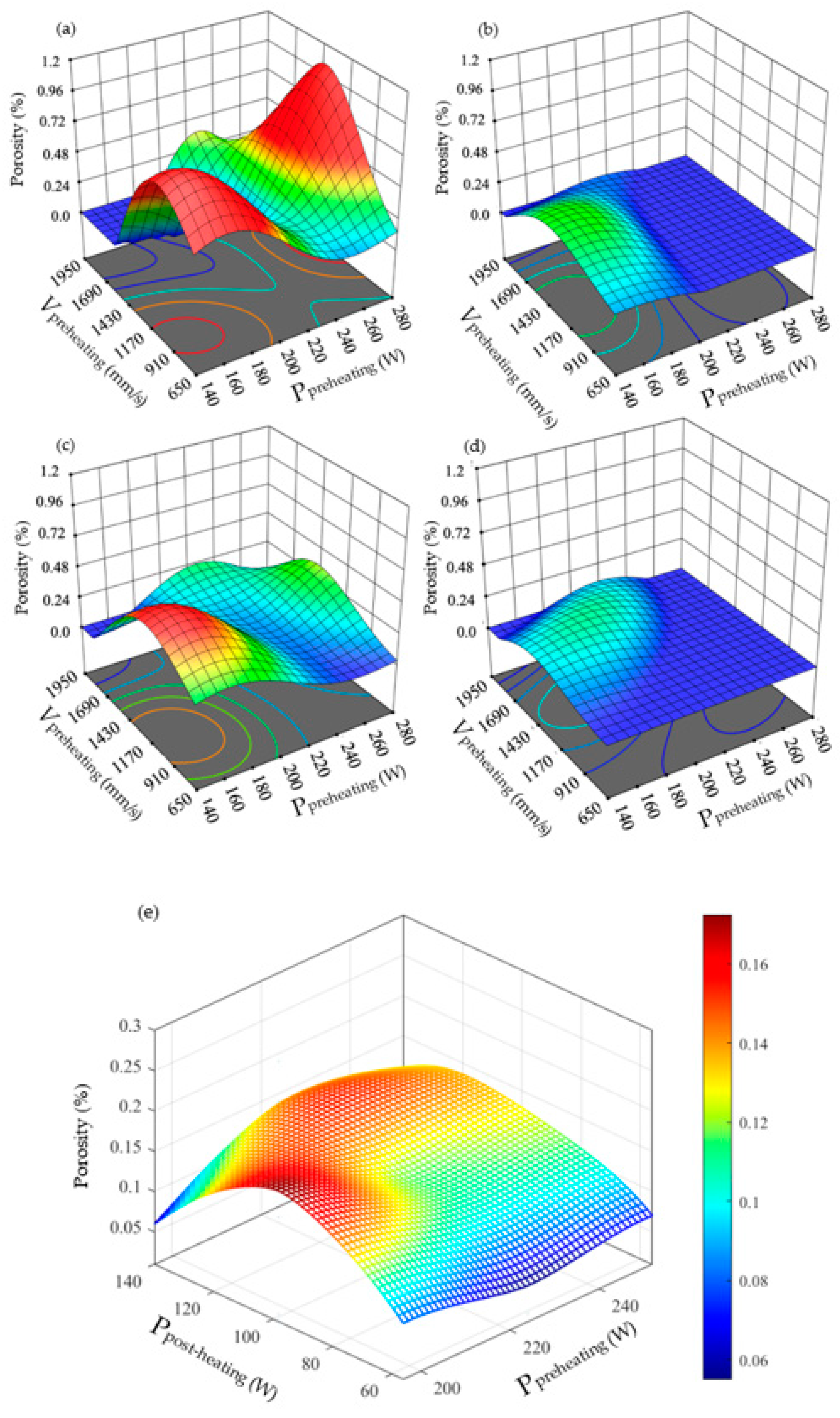
  • Combining layer wise preheating and post-heating laser scanning during the LPBF process improved the relative density up to 99.99% and eliminated the process-induced defects of the Ti-6Al-4V material.
  • In addition to defect improvement, the results showed that there is a noteworthy modification in the material’s microstructure i.e., thickness variation in α/α′ phases’ lath morphology, HCP lattice stretching, and the micro strain mode change with application of the combined layer wise preheating and post-heating laser scan.
  • The results indicate a record level improvement in mechanical response of the material and 37% improvement was noticed among the different scanning strategies during the experimental study of the presented research.
Results indicated that the proposed in-situ thermal processing of the LPBF fabricated Ti-6Al-4V material can alternate the requirement of the post-thermal processes to modify the microstructure for the desired mechanical response in engineering applications.
The investigated process cracked the doors of the future research that will focus on generating higher strength regions in the LPBF-fabricated Ti-6Al-4V for alloying element-free functionally graded regions in the material by applying the proposed scanning strategy selectively to the powder bed during LPBF fabrication.

Author Contributions

Conceptualization, A.A.T.; methodology, A.A.T. and A.A.; software, A.G.-R.; validation, A.A.T., A.G.-R. and A.A.; formal analysis, A.G.-R. and H.H.; investigation, S.H.D. and M.N.S.; resources, A.A.; data curation, A.G.-R. and H.H.; writing—original draft preparation, A.A.T.; writing—review and editing, A.G.-R., S.H.D. and M.N.S.; visualization, A.A.T. and H.H.; supervision, A.A.; project administration, A.A.; funding acquisition, A.A. All authors have read and agreed to the published version of the manuscript.

Funding

This research received no external funding.

Institutional Review Board Statement

Not applicable.

Informed Consent Statement

Not applicable.

Data Availability Statement

Data are contained within the article.

Acknowledgments

The authors are thankful for the characterization equipment provided by the University of Texas at Arlington Characterization Center for Materials and Biology.

Conflicts of Interest

Author Ahmet Alptug Tanrikulu was employed by the company Turkish Aerospace Industries. The remaining authors declare that the research was conducted in the absence of any commercial or financial relationships that could be construed as potential conflicts of interest.

References

  1. Liu, S.; Shin, Y.C. Additive Manufacturing of Ti6Al4V Alloy: A Review. Mater. Des. 2019, 164, 107552. [Google Scholar] [CrossRef]
  2. Tshephe, T.S.; Akinwamide, S.O.; Olevsky, E.; Olubambi, P.A. Additive Manufacturing of Titanium-Based Alloys–A Review of Methods, Properties, Challenges, and Prospects. Heliyon 2022, 8, e09041. [Google Scholar] [CrossRef]
  3. Tanrikulu, A. Microstructure and Mechanical Properties of Additive Manufacturing Titanium Alloys after Thermal Processing. Master’s Thesis, Portland State University, Portland, OR, USA, 2017. [Google Scholar]
  4. Ngo, T.D.; Kashani, A.; Imbalzano, G.; Nguyen, K.T.Q.; Hui, D. Additive Manufacturing (3D Printing): A Review of Materials, Methods, Applications and Challenges. Compos. B Eng. 2018, 143, 172–196. [Google Scholar] [CrossRef]
  5. Rasiya, G.; Shukla, A.; Saran, K. Additive Manufacturing-A Review. Mater. Today Proc. 2021, 47, 6896–6901. [Google Scholar] [CrossRef]
  6. Blakey-Milner, B.; Gradl, P.; Snedden, G.; Brooks, M.; Pitot, J.; Lopez, E.; Leary, M.; Berto, F.; du Plessis, A. Metal Additive Manufacturing in Aerospace: A Review. Mater. Des. 2021, 209, 110008. [Google Scholar] [CrossRef]
  7. Liu, Z.Y.; Li, C.; Fang, X.Y.; Guo, Y.B. Energy Consumption in Additive Manufacturing of Metal Parts. Procedia Manuf. 2018, 26, 834–845. [Google Scholar] [CrossRef]
  8. Peters, M.; Kumpfert, J.; Ward, C.H.; Leyens, C. Titanium Alloys for Aerospace Applications. Adv. Eng. Mater. 2003, 5, 419–427. [Google Scholar] [CrossRef]
  9. Wu, Z.; Narra, S.P.; Rollett, A. Exploring the Fabrication Limits of Thin-Wall Structures in a Laser Powder Bed Fusion Process. Int. J. Adv. Manuf. Technol. 2020, 110, 191–207. [Google Scholar] [CrossRef]
  10. Airbus, L.-A. Landing Gear Sensor Bracket. Available online: https://amfg.ai/2020/01/23/applications-spotlight-3d-printed-brackets/ (accessed on 7 November 2023).
  11. F. 3D Systems, GE Aircraft Bracket. Available online: https://www.3dsystems.com/learningcenter/case-studies/topology-optimization-and-dmp-combine-meet-geaircraft-engine-bracket (accessed on 7 November 2023).
  12. Airbus, E. Hydraulic Spoiler Manifold. Available online: https://www.eos.info/01_parts-andapplications/case_studies_applications_parts/_case_studies_pdf/en_cases/cs_m_aerospace_liebherr_en.pdf (accessed on 7 November 2023).
  13. Airbus, Reflector Bracket. Available online: https://www.eos.info/01_parts-andapplications/case_studies_applications_parts/_case_studies_pdf/en_cases/cs_m_aerospace_airbus_en.pdf (accessed on 7 November 2023).
  14. Airbus, A350 XWB Pylon Bracket. Available online: https://www.airbus.com/newsroom/pressreleases/en/2017/09/first-titanium-3d-printed-part-installed-into-serialproduction-.html (accessed on 7 November 2023).
  15. Karimi, J.; Suryanarayana, C.; Okulov, I.; Prashanth, K.G. Selective Laser Melting of Ti6Al4V: Effect of Laser Re-Melting. Mater. Sci. Eng. A 2021, 805, 140558. [Google Scholar] [CrossRef]
  16. Khorasani, A.M.; Gibson, I.; Ghasemi, A.; Ghaderi, A. Modelling of Laser Powder Bed Fusion Process and Analysing the Effective Parameters on Surface Characteristics of Ti-6Al-4V. Int. J. Mech. Sci. 2020, 168, 105299. [Google Scholar] [CrossRef]
  17. Mishurova, T.; Artzt, K.; Rehmer, B.; Haubrich, J.; Ávila, L.; Schoenstein, F.; Serrano-Munoz, I.; Requena, G.; Bruno, G. Separation of the Impact of Residual Stress and Microstructure on the Fatigue Performance of LPBF Ti-6Al-4V at Elevated Temperature. Int. J. Fatigue 2021, 148, 106239. [Google Scholar] [CrossRef]
  18. Peterson, J.; Issariyapat, A.; Umeda, J.; Kondoh, K. The Effects of Heat Treatment and Carbon Content on the Microstructure and Mechanical Properties of Laser Powder Bed Fusion Ti-6Al-4V with Dissolved TiC Particles. J. Alloys Compd. 2022, 920, 165930. [Google Scholar] [CrossRef]
  19. Ter Haar, G.M.; Becker, T.H. The Influence of Microstructural Texture and Prior Beta Grain Recrystallisation on the Deformation Behaviour of Laser Powder Bed Fusion Produced Ti-6Al-4V. Mater. Sci. Eng. A 2021, 814, 141185. [Google Scholar] [CrossRef]
  20. Liu, J.; Li, G.; Sun, Q.; Li, H.; Sun, J.; Wang, X. Understanding the Effect of Scanning Strategies on the Microstructure and Crystallographic Texture of Ti-6Al-4V Alloy Manufactured by Laser Powder Bed Fusion. J. Mater. Process. Technol. 2022, 299, 117366. [Google Scholar] [CrossRef]
  21. He, Y.; Ma, Y.; Zhang, W.; Wang, Z. Anisotropic Tensile and Fatigue Properties of Laser Powder Bed Fusion Ti6Al4V under High Temperature. Eng. Fract. Mech. 2022, 276, 108948. [Google Scholar] [CrossRef]
  22. Manikandan, P.; Kumar, V.A.; Pradeep, P.I.; Vivek, R.; Manwatkar, S.K.; Rao, G.S.; Murty, S.V.S.N.; Sivakumar, D.; Narayanan, P.R. On the Anisotropy in Room-Temperature Mechanical Properties of Laser Powder Bed Fusion Processed Ti6Al4V-ELI Alloy for Aerospace Applications. J. Mater. Sci. 2022, 57, 9599–9618. [Google Scholar] [CrossRef]
  23. Jamshidi, P.; Aristizabal, M.; Kong, W.; Villapun, V.; Cox, S.C.; Grover, L.M.; Attallah, M.M. Selective Laser Melting of Ti-6Al-4V: The Impact of Post-Processing on the Tensile, Fatigue and Biological Properties for Medical Implant Applications. Materials 2020, 13, 2813. [Google Scholar] [CrossRef]
  24. Xue, M.; Chen, X.; Ji, X.; Xie, X.; Chao, Q.; Fan, G. Effect of Particle Size Distribution on the Printing Quality and Tensile Properties of Ti-6Al-4V Alloy Produced by LPBF Process. Metals 2023, 13, 604. [Google Scholar] [CrossRef]
  25. Eskandari, H.; Lashgari, H.R.; Zangeneh, S.; Kong, C.; Ye, L.; Eizadjou, M.; Wang, H. Microstructural Characterization and Mechanical Properties of SLM-Printed Ti-6Al-4V Alloy: Effect of Build Orientation. J. Mater. Res. 2022, 37, 2645–2660. [Google Scholar] [CrossRef]
  26. Bedmar, J.; de la Pezuela, J.; Riquelme, A.; Torres, B.; Rams, J. Impact of Remelting in the Microstructure and Corrosion Properties of the Ti6Al4V Fabricated by Selective Laser Melting. Coatings 2022, 12, 284. [Google Scholar] [CrossRef]
  27. Farhang, B.; Tanrikulu, A.A.; Ganesh-Ram, A.; Durlov, S.H.; Shayesteh Moghaddam, N. Innovative Fabrication Design for In Situ Martensite Decomposition and Enhanced Mechanical Properties in Laser Powder Bed Fused Ti6Al4V Alloy. J. Manuf. Mater. Process. 2023, 7, 226. [Google Scholar] [CrossRef]
  28. Bartolomeu, F.; Gasik, M.; Silva, F.S.; Miranda, G. Mechanical Properties of Ti6Al4V Fabricated by Laser Powder Bed Fusion: A Review Focused on the Processing and Microstructural Parameters Influence on the Final Properties. Metals 2022, 12, 986. [Google Scholar] [CrossRef]
  29. Kasperovich, G.; Hausmann, J. Improvement of Fatigue Resistance and Ductility of TiAl6V4 Processed by Selective Laser Melting. J. Mater. Process. Technol. 2015, 220, 202–214. [Google Scholar] [CrossRef]
  30. Vrancken, B.; Thijs, L.; Kruth, J.-P.; Van Humbeeck, J. Heat Treatment of Ti6Al4V Produced by Selective Laser Melting: Microstructure and Mechanical Properties. J. Alloys Compd. 2012, 541, 177–185. [Google Scholar] [CrossRef]
  31. Vilaro, T.; Colin, C.; Bartout, J.D. As-Fabricated and Heat-Treated Microstructures of the Ti-6Al-4V Alloy Processed by Selective Laser Melting. Metall. Mater. Trans. A 2011, 42, 3190–3199. [Google Scholar] [CrossRef]
  32. Leuders, S.; Thöne, M.; Riemer, A.; Niendorf, T.; Tröster, T.; Richard, H.A.; Maier, H.J. On the Mechanical Behaviour of Titanium Alloy TiAl6V4 Manufactured by Selective Laser Melting: Fatigue Resistance and Crack Growth Performance. Int. J. Fatigue 2013, 48, 300–307. [Google Scholar] [CrossRef]
  33. Huang, Q.; Liu, X.; Yang, X.; Zhang, R.; Shen, Z.; Feng, Q. Specific Heat Treatment of Selective Laser Melted Ti-6Al-4V for Biomedical Applications. Front. Mater. Sci. 2015, 9, 373–381. [Google Scholar] [CrossRef]
  34. Singla, A.K.; Banerjee, M.; Sharma, A.; Singh, J.; Bansal, A.; Gupta, M.K.; Khanna, N.; Shahi, A.S.; Goyal, D.K. Selective Laser Melting of Ti6Al4V Alloy: Process Parameters, Defects and Post-Treatments. J. Manuf. Process. 2021, 64, 161–187. [Google Scholar] [CrossRef]
  35. Kan, W.H.; Gao, M.; Zhang, X.; Liang, E.; Chiu, N.S.L.; Lim, C.V.S.; Huang, A. The Influence of Porosity on Ti-6Al-4V Parts Fabricated by Laser Powder Bed Fusion in the Pursuit of Process Efficiency. Int. J. Adv. Manuf. Technol. 2022, 119, 5417–5438. [Google Scholar] [CrossRef]
  36. Liu, L.; Chen, C.; Zhao, R.; Wang, X.; Tao, H.; Shuai, S.; Wang, J.; Liao, H.; Ren, Z. In-Situ Nitrogen Strengthening of Selective Laser Melted Ti6Al4V with Superior Mechanical Performance. Addit. Manuf. 2021, 46, 102142. [Google Scholar] [CrossRef]
  37. He, D.; Wang, H.; Huang, W.; Chen, X.; Lian, G.; Wang, Y. Microstructure and Mechanical Properties of LaB6/Ti-6Al-4V Composites Fabricated by Selective Laser Melting. Metals 2023, 13, 264. [Google Scholar] [CrossRef]
  38. Jiang, Q.; Li, S.; Guo, S.; Fu, M.; Zhang, B. Comparative Study on Process-Structure-Property Relationships of TiC/Ti6Al4V and Ti6Al4V by Selective Laser Melting. Int. J. Mech. Sci. 2023, 241, 107963. [Google Scholar] [CrossRef]
  39. Xiao, Y.; Yang, Y.; Wang, D.; Liu, L.; Liu, Z.; Wu, S.; Zhou, H.; Liu, Z.; Song, C. In-Situ Synthesis of High Strength and Toughness TiN/Ti6Al4V Sandwich Composites by Laser Powder Bed Fusion under a Nitrogen-Containing Atmosphere. Compos. B Eng. 2023, 253, 110534. [Google Scholar] [CrossRef]
  40. Tang, M.; Zhang, L.; Zhang, N. Microstructural Evolution, Mechanical and Tribological Properties of TiC/Ti6Al4V Composites with Unique Microstructure Prepared by SLM. Mater. Sci. Eng. A 2021, 814, 141187. [Google Scholar] [CrossRef]
  41. EOS Titanium Ti64 Grade 5 Material Data Sheet Metal Solutions. Available online: https://www.eos.info/03_system-related-assets/material-related-contents/metal-materials-and-examples/metal-material-datasheet/titan/ti64/material_datasheet_eos_titanium_ti64_grade5_en_web.pdf (accessed on 15 April 2024).
  42. Thijs, L.; Verhaeghe, F.; Craeghs, T.; Humbeeck, J.V.; Kruth, J.-P. A Study of the Microstructural Evolution during Selective Laser Melting of Ti-6Al-4V. Acta Mater. 2010, 58, 3303–3312. [Google Scholar] [CrossRef]
  43. Ferreira, S.L.C.; Bruns, R.E.; Ferreira, H.S.; Matos, G.D.; David, J.M.; Brandão, G.C.; da Silva, E.G.P.; Portugal, L.A.; dos Reis, P.S.; Souza, A.S.; et al. Box-Behnken Design: An Alternative for the Optimization of Analytical Methods. Anal. Chim. Acta 2007, 597, 179–186. [Google Scholar] [CrossRef] [PubMed]
  44. Tanrikulu, A.A.; Ganesh-Ram, A.; Farhang, B.; Amerinatanzi, A. Unveiling the Impact of Layerwise Laser Preheating on Microstructure and Mechanical Response in Laser Powder Bed Fusion. J. Mater. Sci. 2023, 58, 17362–17382. [Google Scholar] [CrossRef]
  45. Schneider, C.A.; Rasband, W.S.; Eliceiri, K.W. NIH Image to ImageJ: 25 Years of Image Analysis. Nat. Methods 2012, 9, 671–675. [Google Scholar] [CrossRef] [PubMed]
  46. Khorsand Zak, A.; Majid, W.H.A.; Abrishami, M.E.; Yousefi, R. X-Ray Analysis of ZnO Nanoparticles by Williamson-Hall and Size-Strain Plot Methods. Solid. State Sci. 2011, 13, 251–256. [Google Scholar] [CrossRef]
  47. Bagasol, A.J.I.; Kaschel, F.R.; Ramachandran, S.; Mirihanage, W.; Browne, D.J.; Dowling, D.P. The Influence of a Large Build Area on the Microstructure and Mechanical Properties of PBF-LB Ti-6Al-4 V Alloy. Int. J. Adv. Manuf. Technol. 2023, 125, 1355–1369. [Google Scholar] [CrossRef]
  48. Pasang, T.; Tavlovich, B.; Yannay, O.; Jakson, B.; Fry, M.; Tao, Y.; Turangi, C.; Wang, J.C.; Jiang, C.P.; Sato, Y.; et al. Directionally-Dependent Mechanical Properties of Ti6Al4V Manufactured by Electron Beam Melting (EBM) and Selective Laser Melting (SLM). Materials 2021, 14, 3603. [Google Scholar] [CrossRef]
  49. Zhao, Z.; Chen, J.; Lu, X.; Tan, H.; Lin, X.; Huang, W. Formation Mechanism of the α Variant and Its Influence on the Tensile Properties of Laser Solid Formed Ti-6Al-4V Titanium Alloy. Mater. Sci. Eng. A 2017, 691, 16–24. [Google Scholar] [CrossRef]
  50. Baufeld, B.; van der Biest, O. Mechanical Properties of Ti-6Al-4V Specimens Produced by Shaped Metal Deposition. Sci. Technol. Adv. Mater. 2009, 10, 015008. [Google Scholar] [CrossRef]
  51. Cao, S.; Zou, Y.; Lim, C.V.S.; Wu, X. Review of Laser Powder Bed Fusion (LPBF) Fabricated Ti-6Al-4V: Process, Post-Process Treatment, Microstructure, and Property. Light Adv. Manuf. 2021, 2, 1. [Google Scholar] [CrossRef]
  52. Tanrikulu, A.A.; Ganesh-Ram, A.; Farhang, B.; Amerinatanzi, A. Comparison of Layerwise Preheating and Post-Heating Laser Scan on The Microstructure and Mechanical Properties of L-PBF Ti6Al4V. In Proceedings of the 2023 Annual International Solid Freeform Fabrication Symposium–An Additive Manufacturing Conference, Austin, TX, USA, 14–16 August 2023. [Google Scholar]
  53. Tanrikulu, A.A.; Farhang, B.; Ganesh-Ram, A.; Hekmatjou, H.; Durlov, S.H.; Amerinatanzi, A. In Situ Microstructure Modification Using a Layerwise Surface-Preheating Laser Scan of Ti-6Al-4V during Laser Powder Bed Fusion. Materials 2024, 17, 1929. [Google Scholar] [CrossRef]
  54. Ganesh-Ram, A.; Tanrikulu, A.A.; Valdez Loya, O.; Davidson, P.; Ameri, A. In-Situ Reinforcement Processing for Laser Powder Bed Fused Ti64 Parts. In Proceedings of the Solid Freeform Fabrication, Austin, TX, USA, 14–16 August 2023. [Google Scholar]
  55. Xu, Y.; Lu, Y.; Sundberg, K.L.; Liang, J.; Sisson, R.D. Effect of Annealing Treatments on the Microstructure, Mechanical Properties and Corrosion Behavior of Direct Metal Laser Sintered Ti-6Al-4V. J. Mater. Eng. Perform. 2017, 26, 2572–2582. [Google Scholar] [CrossRef]
  56. Pal, S.; Gubeljak, N.; Hudák, R.; Lojen, G.; Rajťúková, V.; Brajlih, T.; Drstvenšek, I. Evolution of the Metallurgical Properties of Ti-6Al-4V, Produced with Different Laser Processing Parameters, at Constant Energy Density in Selective Laser Melting. Results Phys. 2020, 17, 103186. [Google Scholar] [CrossRef]
  57. Li, Z.; Li, H.; Yin, J.; Li, Y.; Nie, Z.; Li, X.; You, D.; Guan, K.; Duan, W.; Cao, L.; et al. A Review of Spatter in Laser Powder Bed Fusion Additive Manufacturing: In Situ Detection, Generation, Effects, and Countermeasures. Micromachines 2022, 13, 1366. [Google Scholar] [CrossRef]
  58. Yasa, E.; Kruth, J.-P. Microstructural Investigation of Selective Laser Melting 316L Stainless Steel Parts Exposed to Laser Re-Melting. Procedia Eng. 2011, 19, 389–395. [Google Scholar] [CrossRef]
  59. Jamhari, F.I.; Foudzi, F.M.; Buhairi, M.A. Effect of HIP on Porosity of Ti6Al4V Manufactured by Laser Powder Bed Fusion: A Brief Review. In Proceedings of the 7th International Conference and Exhibition on Sustainable Energy and Advanced Materials (ICE-SEAM 2021), Melaka, Malaysia, 23 November 2021; Abdollah, M.F.B., Amiruddin, H., Phuman Singh, A.S., Abdul Munir, F., Ibrahim, A., Eds.; Springer Nature: Singapore, 2022; pp. 22–25. [Google Scholar]
  60. Cepeda-Jiménez, C.M.; Potenza, F.; Magalini, E.; Luchin, V.; Molinari, A.; Pérez-Prado, M.T. Effect of Energy Density on the Microstructure and Texture Evolution of Ti-6Al-4V Manufactured by Laser Powder Bed Fusion. Mater. Charact. 2020, 163, 110238. [Google Scholar] [CrossRef]
  61. Neikter, M.; Åkerfeldt, P.; Pederson, R.; Antti, M.L. Microstructure Characterisation of Ti-6Al-4V from Different Additive Manufacturing Processes. IOP Conf. Ser. Mater. Sci. Eng. 2017, 258, 012007. [Google Scholar] [CrossRef]
  62. Villa, M.; Brooks, J.W.; Turner, R.P.; Ward, M. Microstructural Modeling of Thermally-Driven β Grain Growth, Lamellae & Martensite in Ti-6Al-4V. Model. Numer. Simul. Mater. Sci. 2020, 10, 55–73. [Google Scholar] [CrossRef]
  63. Pantawane, M.V.; Ho, Y.H.; Joshi, S.S.; Dahotre, N.B. Computational Assessment of Thermokinetics and Associated Microstructural Evolution in Laser Powder Bed Fusion Manufacturing of Ti6Al4V Alloy. Sci. Rep. 2020, 10. [Google Scholar] [CrossRef] [PubMed]
  64. Huang, J.-Y.; Chang, C.-H.; Wang, W.-C.; Chou, M.-J.; Tseng, C.-C.; Tu, P.-W. Systematic Evaluation of Selective Fusion Additive Manufacturing Based on Thermal Energy Source Applied in Processing of Titanium Alloy Specimens for Medical Applications. Int. J. Adv. Manuf. Technol. 2020, 109, 2421–2429. [Google Scholar] [CrossRef]
  65. Farabi, E.; Tari, V.; Hodgson, P.D.; Rohrer, G.S.; Beladi, H. On the Grain Boundary Network Characteristics in a Martensitic Ti-6Al-4V Alloy. J. Mater. Sci. 2020, 55, 15299–15321. [Google Scholar] [CrossRef]
  66. Gong, J.; Wilkinson, A.J. Anisotropy in the Plastic Flow Properties of Single-Crystal α Titanium Determined from Micro-Cantilever Beams. Acta Mater. 2009, 57, 5693–5705. [Google Scholar] [CrossRef]
  67. Muiruri, A.; Maringa, M.; du Preez, W. Evaluation of Dislocation Densities in Various Microstructures of Additively Manufactured Ti6Al4V (Eli) by the Method of X-Ray Diffraction. Materials 2020, 13, 5355. [Google Scholar] [CrossRef] [PubMed]
  68. Hasegawa, M. Ellingham Diagram. In Treatise on Process. Metallurgy; Elsevier: Amsterdam, The Netherlands, 2014; pp. 507–516. [Google Scholar]
  69. Chen, Z.; Wang, X.; Giuliani, F.; Atkinson, A. Microstructural Characteristics and Elastic Modulus of Porous Solids. Acta Mater. 2015, 89, 268–277. [Google Scholar] [CrossRef]
  70. Kováčik, J. Correlation between Young’s Modulus and Porosity in Porous Materials. J. Mater. Sci. Lett. 1999, 18, 1007–1010. [Google Scholar] [CrossRef]
  71. Bandyopadhyay, A.; Espana, F.; Balla, V.K.; Bose, S.; Ohgami, Y.; Davies, N.M. Influence of Porosity on Mechanical Properties and in Vivo Response of Ti6Al4V Implants. Acta Biomater. 2010, 6, 1640–1648. [Google Scholar] [CrossRef]
  72. Brandl, E.; Palm, F.; Michailov, V.; Viehweger, B.; Leyens, C. Mechanical Properties of Additive Manufactured Titanium (Ti-6Al-4V) Blocks Deposited by a Solid-State Laser and Wire. Mater. Des. 2011, 32, 4665–4675. [Google Scholar] [CrossRef]
  73. Meng, L.X.; Yang, H.J.; Ben, D.D.; Ji, H.B.; Lian, D.L.; Ren, D.C.; Li, Y.; Bai, T.S.; Cai, Y.S.; Chen, J.; et al. Effects of Defects and Microstructures on Tensile Properties of Selective Laser Melted Ti6Al4V Alloys Fabricated in the Optimal Process Zone. Mater. Sci. Eng. A 2022, 830, 142294. [Google Scholar] [CrossRef]
Figure 1. Laser scanning strategy sequence: (1) Powder spreading from the dispenser onto the building plate. (2) Preheating the selective powder regions corresponding to the scanning pattern of the fabrication geometry. (3) Melting laser scan of the fabrication geometry. (4) Final, post-heating scan of the melted regions.
Metals 14 00629 g001
Figure 2. Tensile testing sample.
Metals 14 00629 g002
Figure 3. SEM images of (a) the reference (as-built) sample without any additional laser scan and (b) the in-situ thermal process sample (196 W preheating laser scan power, 1950 mm/s preheating laser scan speed + 56 W post-heating laser scan power, 1300 mm/s post-heating laser scan speed).
Metals 14 00629 g003
Figure 4. Influence of the applied single (a) preheating laser scan energy density on porosity, (b) single post-heating laser scan energy density on porosity. The porosity level of the reference sample without any additional laser scan is depicted with a red triangle marker in both figures.
Metals 14 00629 g004
Figure 5. Response surface plots of the impact of the in-situ thermal processing through the combination of preheating and post-heating laser scan on porosity. (a) Effect of the preheating laser scan parameters at constant post-heating laser parameters of 56 W laser power and 1300 mm/s laser scan speed which include case 23. (b) Preheating laser scan parameters impact at constant post-heating laser parameters of 56 W laser power and 975 mm/s laser scan speed which include case 3. (c) Preheating laser scan parameters impact constant post-heating laser parameters of 98 W laser power and 1300 mm/s laser scan speed which include case 10. (d) Effect of the preheating laser scan speed parameters, the post-heating laser scan of 56 W laser power and 650 mm/s laser scan speed which include case 19. (e) Surface response of porosity levels based on selected preheating and post-heating laser powers, revealing that lower post-heating laser scan power exhibits less porosity.
Metals 14 00629 g005
Figure 6. Response surface plots of the impact of the in-situ thermal processing through the combination of preheating and post-heating laser scan on α/α′ phase lath thickness. Lower post-heating laser power combined with moderate preheating laser scan powers delivered lower lath thickness.
Metals 14 00629 g006
Figure 7. The XRD patterns of the reference (as-built) and the in-situ thermally processed samples including case 3 (preheating: P = 252 W, V = 1625 mm/s, post-heating: 56 W, V = 975 mm/s), case 10 (preheating: P = 224 W, V = 1950 mm/s, post-heating: 98 W, V = 650 mm/s), case 19 (preheating: P = 252 W, V = 1950 mm/s, post-heating: 56 W, V = 650 mm/s), and case 23 (preheating: P = 196 W, V = 1950 mm/s, post-heating: 56 W, V = 1300 mm/s).
Metals 14 00629 g007
Figure 8. The micro strain values were derived from the slope of the fitted linear trendline in the W–H analysis for different in-situ thermal processing conditions. (a) Case 3 (preheating: P = 252 W, V = 1625 mm/s, post-heating: 56 W, V = 975 mm/s), (b) case 10 (preheating: P = 224 W, V = 1950 mm/s, post-heating: 98 W, V = 650 mm/s), (c) case 19 (preheating: P = 252 W, V = 1950 mm/s, post-heating: 56 W, V = 650 mm/s), and (d) case 23 (preheating: P = 196 W, V = 1950 mm/s, post-heating: 56 W, V = 1300 mm/s). (e) Reference sample without any additional laser scan application.
Metals 14 00629 g008
Figure 9. Effect of the in-situ thermal processing on HCP lattice parameters. (a) The total energy of the preheating and post-heating laser scans effect on lattice parameter “a”. (b) Lattice parameter “c”. (c) Lattice distortion variation at different total energy inputs.
Metals 14 00629 g009
Figure 10. Stress–strain plot of the reference (as-built) and the in-situ thermally processed specimens including case 3 (preheating: P = 252 W, V = 1625 mm/s, post-heating: 56 W, V = 975 mm/s); case 10 (preheating: P = 224 W, V = 1950 mm/s, post-heating: 98 W, V = 650 mm/s); case 19 (preheating: P = 252 W, V = 1950 mm/s, post-heating: 56 W, V = 650 mm/s); and case 23 (preheating: P = 196 W, V = 1950 mm/s, post-heating: 56 W, V = 1300 mm/s).
Metals 14 00629 g010
Figure 11. Localized strain contour maps of εyy from the DIC image analysis. (a) Reference sample (only melting laser scan). (b) Case 3 (preheating: P = 252 W, V = 1625 mm/s, post-heating: 56 W, V = 975 mm/s). (c) Case 10 (preheating: P = 224 W, V = 1950 mm/s, post-heating: 98 W, V = 1300 mm/s). (d) Case 19 (preheating: P = 252 W, V = 1950 mm/s, post-heating: 56 W, V = 650 mm/s). (e) Case 23 (preheating: P = 190 W, V = 1950 mm/s, post-heating: 98 W, V = 650 mm/s).
Metals 14 00629 g011
Figure 12. Microstructure of the LPBF-fabricated Ti-6Al-4V. (a) As-built condition without any additional laser scan. The average lath thickness is 0.797 µm and the “c/a” ratio of the HCP lattice is 1.5904. (b) Case 3 (preheating: P = 252W, V = 1625 mm/s, post-heating: 56 W, V = 975 mm/s): the average lath thickness is 0.812 and c/a of the HCP lattice is 1.5942. (c) Case 10 (preheating: P = 224 W, V = 1950 mm/s, post-heating: 98 W, V = 1300 mm/s): the average lath thickness is 0.792 and c/a of the HCP lattice is 1.5960. (d) Case 19 (preheating: P = 252 W, V = 1950 mm/s, post-heating: 56 W, V = 650 mm/s): the average lath thickness is 0.793 and c/a of the HCP lattice is 1.5983. (e) Case 23 (preheating: P = 190 W, V = 1950 mm/s, post-heating: 98 W, V = 650 mm/s): the average lath thickness is 0.808 and c/a of the HCP lattice is 1.6025.
Metals 14 00629 g012
Figure 13. Lattice deformation with the additional interstitial oxygen atoms in the octahedral positions during in-situ thermal processing of the LPBF-fabricated Ti-6Al-4V.
Metals 14 00629 g013
Table 1. Various Combinations of the Process Parameters for Preheating and Post-heating Laser Exposure Delivered by DOE with Energy Input Constraint (<45 J/mm3).
#.Preheating
Laser
Power (W)
Preheating
Laser
Speed (mm/s)
E_Preheating
(J/mm3)
Post Heating
Laser Power
(W)
Post Heating
Laser Speed
(mm/s)
E_Postheating
(J/mm3)
E_Total
(J/mm3)
1196130031.415697511.9743.38
2196130031.415613008.9740.38
3252162532.315697511.9744.27
4252162532.315613008.9741.28
5196162525.135697511.9737.09
6196162525.1398130015.7140.83
7196162525.135665017.9543.08
8224195023.935697511.9735.90
9224195023.939897520.9444.87
10224195023.9398130015.7139.64
11224195023.935613008.9732.91
12224195023.935665017.9541.88
13224162528.725697511.9740.68
14224162528.7298130015.7144.42
15224162528.725613008.9737.69
16224130035.905613008.9744.87
17252195026.925697511.9738.89
18252195026.9298130015.7142.63
19252195026.925665017.9544.87
20252195026.925613008.9735.90
21224130035.905613008.9744.87
22196195020.9498130015.7136.65
23196195020.945613008.9729.91
24196195020.945665017.9538.89
25196195020.945697511.9732.91
26224195023.935697511.9735.90
27196195020.949897520.9441.88
Table 2. Porosity in as-fabricated parts by laser parameters. Comparing porosity levels for each combination of preheating and post-heating laser settings.
#Preheating
Laser Power
(W)
Preheating
Laser Speed
(mm/s)
Post-Heating
Laser Power
(W)
Post-Heating
Laser Speed
(mm/s)
AVE (%)STD (%)
11961300569750.060.04
219613005613000.070.07
32521625569750.020.01
425216255613000.520.84
51961625569750.100.07
619616259813000.140.12
71961625566500.190.15
82241950569750.380.27
92241950989750.060.03
1022419509813000.020.01
1122419505613000.380.71
122241950566500.100.07
132241625569750.040.02
1422416259813000.120.12
1522416255613000.100.08
1622413005613000.070.06
172521950569750.060.02
1825219509813000.140.25
192521950566500.010.01
2025219505613000.110.10
2122413005613000.080.06
2219619509813000.140.24
2319619505613000.010.01
241961950566500.070.05
251961950569750.060.04
262241950569750.030.03
271961950989750.040.02
Disclaimer/Publisher’s Note: The statements, opinions and data contained in all publications are solely those of the individual author(s) and contributor(s) and not of MDPI and/or the editor(s). MDPI and/or the editor(s) disclaim responsibility for any injury to people or property resulting from any ideas, methods, instructions or products referred to in the content.

