Article

Corrosion Performance of Welded Joints for E40 Marine Steel

1
State Collaborative Innovation Centre of Steel Technology, University of Science and Technology Beijing, Beijing 100083, China
2
Research Institute, Nanjing Iron & Steel Co., Ltd., Nanjing 210035, China
*
Author to whom correspondence should be addressed.
Metals 2023, 13(9), 1528; https://doi.org/10.3390/met13091528
Submission received: 10 July 2023 / Revised: 19 August 2023 / Accepted: 25 August 2023 / Published: 28 August 2023
(This article belongs to the Special Issue Thermodynamic Properties of Metallurgical Melts)

Abstract

:
Marine steel requires excellent toughness and corrosion resistance in a low-temperature seawater environment. In this study, corrosion tests on E40 steel were performed, including electrochemical testing of the weld metal and heat-affected zone, dynamic corrosion testing in a simulated seawater environment, and the analysis and comparison of results obtained using different methods. The corrosion resistance of E40 was determined by measuring the saturation current density of the anodic dissolution of the steel in a corrosive medium by an electrochemical method. Under laboratory conditions, the corrosion resistance was investigated under simulated seawater. The results showed that regions with uneven microhardness corresponded to the inhomogeneity of the corrosion potential, with measured fluctuations of up to 40 mV. Nanoscale corrosive–aggressive non-metallic inclusions served as a substrate for the deposition of titanium and niobium carbonitrides, thereby weakening the corrosion resistance. The corrosion rate of the base metal was 1.16–1.64 mm/year, which was slightly higher than that of the heat-affected zone. The influence of deposition on the corrosion performance of welded joints under different deoxygenation processes was studied, and the deposition composition was controlled by a deoxygenation process to improve the corrosion resistance of the steel plate.

1. Introduction

Low-temperature steels, which are used as marine engineering steels, are required to exhibit strong toughness matching and good corrosion resistance to seawater. Welding, as one of the most important connection forms for steel in infrastructure, has been widely used in the production and assembly of structural components, particularly for some weld steel structures working in the conditions of an aggressive corrosion environment, such as bridges and marine structures, where fractures and fatigue damage due to serious corrosion in weld zones are the main threats to the structure’s service reliability and safety [1]. Any type of construction has to be sufficiently resistant to corrosion, just as it has to be sufficiently resistant to mechanical fracture [2]. The welding materials used to bond marine steels should ensure that the strength and cold resistance of the seam metal are not below those of the base metal and provide corrosion resistance against seawater. To increase the strength and other characteristics of seam metals, welding materials are alloyed with different elements that harden the solid solution and shift the γ→α microstructural transformation toward lower temperatures, leading to stronger fine-grained structures. The molten weld metal solidifies as a cast structure, which may not have the same composition as the parent material but will certainly have a different metallographic structure. Both of these factors may make its corrosion behavior different from that of the surrounding parent material [3].
Xu et al. studied the time-varying trends of pitting geometrical features for the different zones of Q235 welded joints, as well as the effect of pitting damage on the mechanical properties and fracture behaviors of welded joints [4]. The corrosion resistance of different positions on the joint surface and its effect on joint properties have been investigated under different solutions by Li et al. [5]. The microstructural evolution, mechanical properties, and corrosion performance of the thermomechanically affected zone and heat-affected zone were mainly studied to reveal the relationship between the microstructure and properties in different solutions. Sinhmar et al. studied the corrosion behavior of friction stir welding joints of Al alloys and investigated the role of precipitates in ensuring the corrosion potential of the joint [6]. A potential difference between the precipitates and the matrix resulted in the dissolution of the anodic part and led to corrosion. Qi et al. focused on the influence of the ratio of ferrite/austenite and the formation of precipitation on the corrosion properties of two types of super duplex stainless steel welding joints [7]. The weld microstructure under the crystallization of the high-temperature welding pool will show a certain extent of performance weakening, and the precipitation of the second phase also influences the micro-corrosion tendency of the weld matrix. The addition of alloying elements can effectively improve the corrosion behavior of welding joints. Moreover, the existence of a multiphase structure in the matrix can also induce corrosion [8,9]. Furthermore, the heat input has a significant effect on the microstructure and corrosion performance of welded joints. Wang et al. studied high-strength low-alloy E40 steels with different heat inputs formed by underwater wet welding. The corrosion performance of the base metal, weld metal, and heat-affected zone was investigated [10]. The results indicated that the corrosion resistance of the WM decreased with increasing heat input for a constant welding speed. An excessively high welding speed can cause severe deterioration in the corrosion resistance of the WM.
The current corrosion research of welding joints mainly focuses on stainless steel and austenitic steel. The corrosion properties of marine steel welded joints under different deoxygenic smelting processes have not been deeply studied. Welding is an important means of connection in the process of marine platform manufacturing, and high-strength and low-temperature resistance in the environment are the main challenges. The welding metal and welding thermal influence area are the weak links in the welding structure, and its strength, toughness, and corrosion resistance have a very important impact on the safety of the whole welding structure, so it is necessary to study the corrosion of the welding joints of marine structural steel. In this study, the corrosion properties of the welded joints of a typical steel type of marine steel E40 were evaluated by various methods, including electrochemical tests on the WM and HAZ and dynamic corrosion tests in simulated seawater. The compositions of non-metallic inclusions and other structural features were analyzed.

2. Materials and Methods

2.1. Test Materials

The steel specimens were prepared in a 150-ton furnace and then hot-rolled into plates of 30 mm thickness and finally air-cooled to room temperature at approximately 25 °C. The refining deoxidation process of Steel A was conducted as follows. Si–Mn alloy was added to eliminate oxygen. Al was added at the ladle furnace. Oxygen was blown during the RH process to modify the inclusions. The conditions for this process were as follows: 50 m3 oxygen blowing and RH post-calcium treatment. The refining deoxidation process of Steel B was a low-Al deoxidation process. Si–Mn alloys and Al were added to eliminate oxygen. Furthermore, instead of adding Al at the ladle furnace, an Al wire was added at the final stage of the Ruhrstahl–Heraeus (RH) degassing process. Then, Ca treatment was conducted for 2–3 min.
Approximately 10 samples of E40 steel plates with thicknesses of 30 mm were provided by Nanjing Iron & Steel Co., Ltd., (Nanjing, China) for testing. The actual chemical compositions of the different steels were analyzed using a Spectro Lab emission spectrometer. The chemical compositions of the two steel plates (A and B) are shown in Table 1. The steel plates were welded using submerged arc welding. PremierWeld Ni1K wire (Lincoln Electric, Cleveland, OH, USA) with a diameter of 4.0 mm was used as the submerged arc wire with the PremierWeld 8500 welding agent (Lincoln Electric). The chemical composition of the fused metal was 0.08 C, 0.56 Si, 1.15 Mn, 0.004 S, 0.012 P, 0.83 Ni, 0.07 Cr, and 0.001 Mo (wt%); others included Fe.

2.2. Welding

The size of the test plates used for automatic submerged arc welding was 800 mm × 200 mm. The length direction of the test plate was aligned parallel to the rolling direction of the steel plate. Symmetrical X-type grooves were cut into the plates, giving a 90° angle of the welding groove (Figure 1). Welding was performed using a current of 780 ± 10 A, arc voltage of 38 ± 2 V, speed of 36 ± 1 cm/min, and heat input of 49 ± 2 kJ/cm. Welding was performed from two sides. The first seam was welded in one pass and then the plate was turned over and the second seam was welded on the opposite side in one pass.

2.3. Characterization Methods

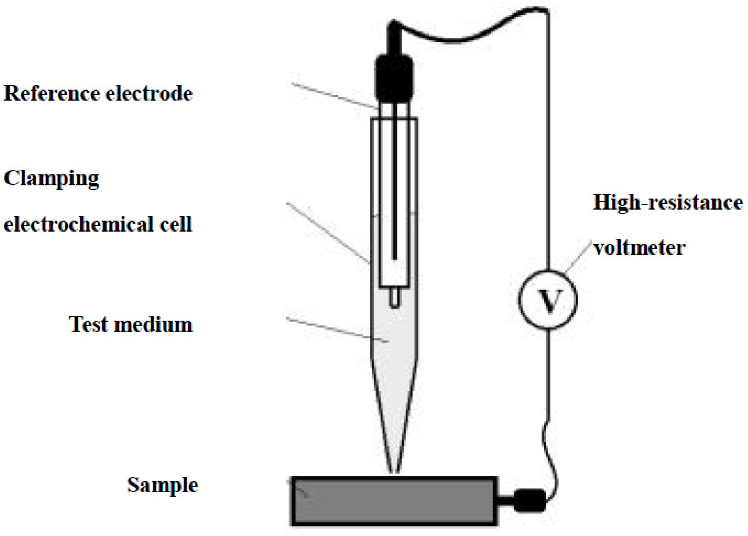
2.3.1. Electrochemical Tests

Measurements of the free-corrosion potentials in different zones of the welded samples were performed. First, the reinforcement of the welded joint was removed from the working surface of the sample (length of 150–160 mm and width of 20–30 mm) by grinding the surface to a roughness of 0.8–1.2 μm. Then, the samples were degreased with ethanol before testing. The tests were performed by measuring the local potential of an open circuit using a clamping electrochemical cell (see Figure 2) in contact with the surface of the test sample. An area of the metal surface with a diameter of 1 mm (limited by the area of the clamping device) was used as the working electrode. The electrochemical cell (ESR-10101) contained a double-junction Ag/AgCl reference electrode with an inner compartment containing 3 M aqueous KCl solution and an outer compartment filled with the test medium (aqueous solution of 5 wt% NaCl as simulated seawater). The open circuit potential was measured using a high-resistance voltmeter as the electrochemical cell was moved in a line along the sample surface, to analyze the base metal, HAZ, and WM. Measurements were taken every 5 mm and the duration of each test was 30 min.
The corrosion resistance of the steel samples in this study was determined by measuring the saturation current density of their anodic dissolution in a corrosive medium via an electrochemical method. Several specimens with dimensions of 30 mm × 10 mm × 6 mm were cut from the welded plates. The samples were potentiostatically aged in a three-electrode cell at a potential of 300 mV in a 0.5 M NaCl solution at 25 °C for 1 h. The saturation current density after aging was used to predict the corrosion resistance of the steel under specific operating conditions.

2.3.2. Metallographic Tests

Metallographic studies were performed using an Axiovert 40 MAT EN 61010-1 metallographic microscope. Furthermore, an analytical transmission electron microscope (JEM200CX, JEOL, Tokyo, Japan) was used to study the microstructure and particles of proeutectoid constituents. The types of inclusions and proeutectoid constituents were determined by electron microdiffraction. The specimens used for microstructural analysis were prepared using the polishing machine SS-2000 Leco. The specimens were ground by a series of emery papers (up to grade 1200) and mechanically polished to a mirror view using aqueous diamond suspensions with particle sizes of 3 µm and a fine silica suspension with particle sizes of 0.05 µm. The polished samples were degreased with ethanol. The hardness of the steel was measured using a Buehler 5101 Vickers micrometer with a load of 500 g.

3. Results

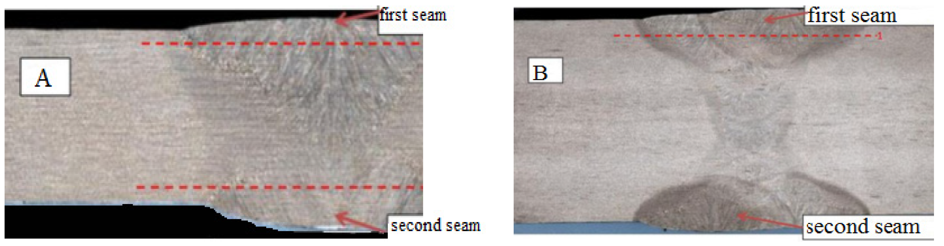
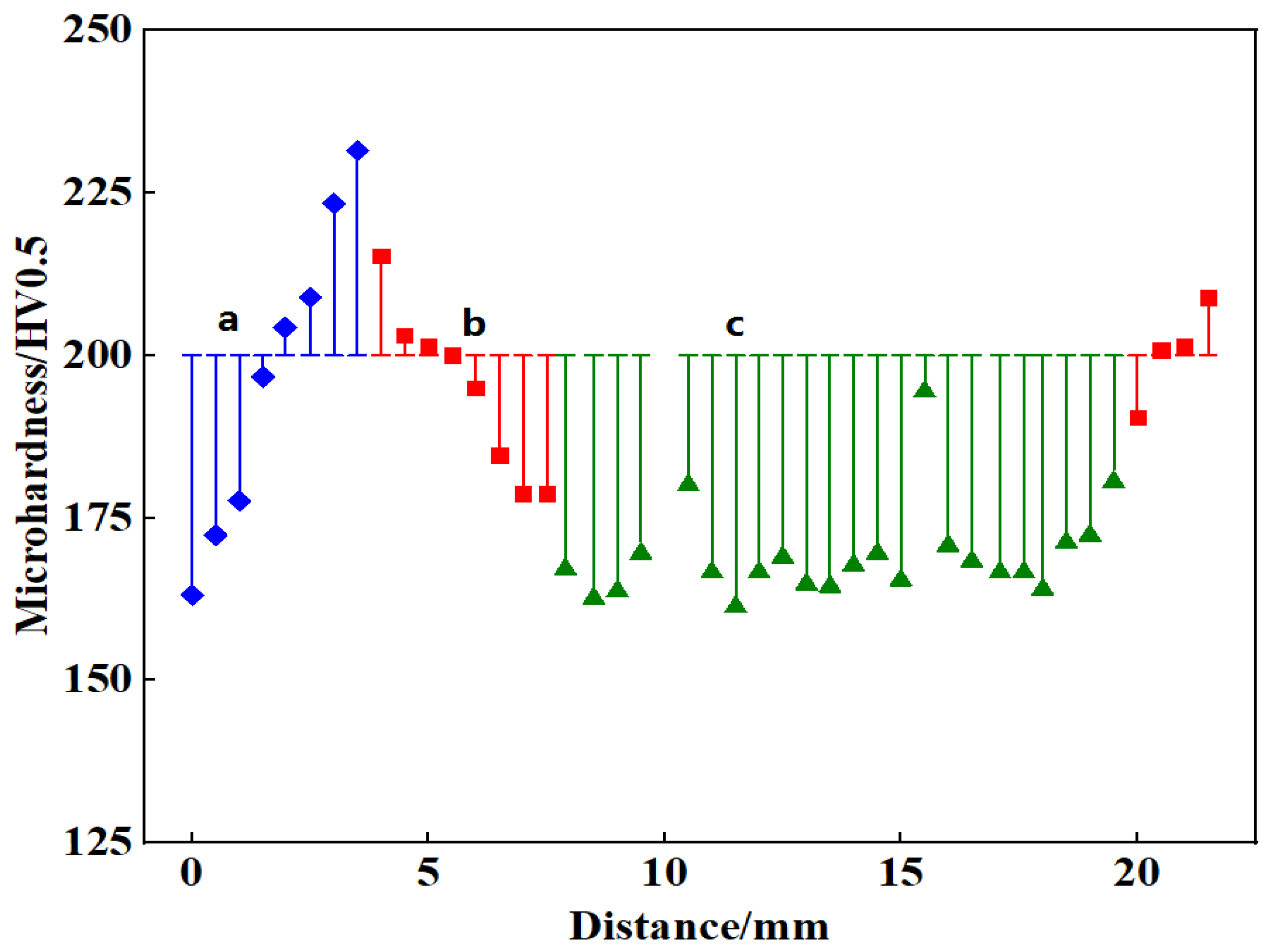
3.1. Microstructure and Microhardness of Welded Joints

Figure 3 displays the macrostructures of the welded joints of the samples and surface regions (indicated by arrows), where the paths used to measure the microhardness are indicated by dashed lines. The near-weld area contains a mixture of acicular ferrite and bainite. The joint areas near the fusion zone contain zones of columnar crystals formed during the crystallization of the first seam. The central part of the first seam contains a fine-grained ferrite–perlite structure, which was formed due to recrystallization from the additional heat input during the formation of the second seam.
Figure 4 and Figure 5 show the microhardness results for Steels A and B, respectively, along with the corresponding microstructures of the various welded joint areas, including the near-weld area. Figure 4 shows that the microhardness of the first seam metal of Steel A increases approaching the weld area, reaching a maximum value of 230 HV near the fusion line characterized by the bainitic structure. Then, the microhardness decreases in the area with columnar crystals (200 HV), and then remains quite constant in the recrystallization area (170 HV). In the case of Steel B, Figure 5 shows that the microstructure of the HAZ is a ferrite–bainite mixture, while the seam metal contains areas of columnar crystals and recrystallization characterized by a fine-grained mixture of acicular ferrite and bainite. The microhardness of the welded seam of Steel B increased from 170 HV in the base metal to 240 HV in the middle of the seam. The near-weld hardness did not exceed the value measured for the area of the seam metal with columnar crystals. The maximum microhardness was measured in the recrystallization area, which was attributed to the formation of the bainitic structure and also ascribable to the high density of fine intragranular precipitates [11]. The lower ferrite content and the microhardness also decreased with the decrease in the ferrite phase [12]. Generally, hardness usually implies resistance to plastic deformation [13].

3.2. Corrosion Rate in a Moving Environment Simulator

Using electrochemical techniques, it is possible to determine the behavior of electrochemical corrosion in materials, such as corrosion rates, corrosion potentials and currents, and types of corrosion [14]. The test procedure is described in detail in the test methods [15]. The test duration was 240 h. An evaluation of the corrosion resistance of various areas of the welded samples with the removal of the reinforcement of the welded seam was carried out according to the results of the measurement of the depth of corrosive dissolution with respect to the contour surface. According to the average depth of corrosive dissolution in the area of the base metal, HAZ, and seam metal, the corrosion rate was calculated by the formula k = h c p 240 × 8760 (mm/year). The results are shown in Figure 6.
Table 2 shows the distribution of the corrosion rates of individual parts of the surfaces of welded samples.
It can be seen from Table 2 that the corrosion rate of the base metal is slightly higher than that of the other parts of the welded seam, which is explained by the presence in the metal of the corrosive–aggressive non-metallic inclusion base. At the same time, the corrosion rate of the base metal and the thermal influence area of plate B are higher than those of plate A, which is related to the different deoxygenation processes of the two plates.
As seen in Figure 6, an assessment of the steel plate surface was carried out with a microscope. Local corrosion was found. Steel B showed more severe corrosion than Steel A. There was more serious corrosion damage to the seam metal and near-weld area. It is possible that the formation of local corrosion damage in the sample of Steel B is associated with the more negative potentials of free corrosion of the base metal and weld line, as well as the structural area on the weld surface—for example, with a recrystallization structure—which may have led to the local corrosion damage of these areas.

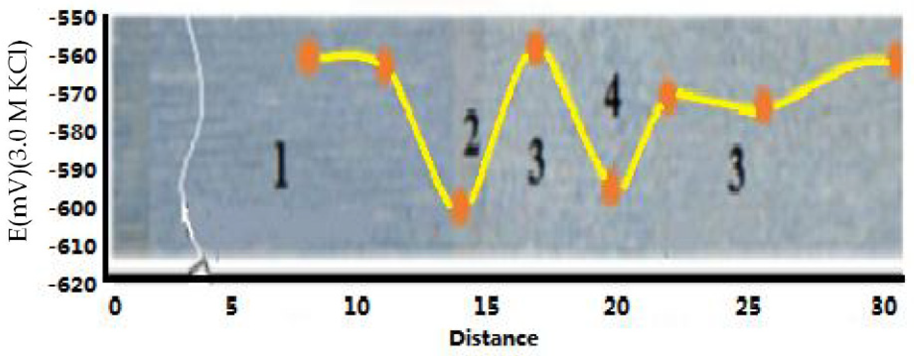
3.3. Free Corrosion Potential of Welded Joints

The corrosion resistance of the welded joints was investigated using various methods, as described above. One surface of Steel A and one surface of Steel B were measured as the welded seams on the samples were symmetrical considering the axial area. Figure 7 and Figure 8 show the distribution of the free corrosion potential over the surfaces of the welded samples. The region with the lowest free corrosion potential was the fusion zone of Steel B, where recrystallization occurred and defects formed during testing. The plots show oscillations of up to ~40 mV in the potential, indicating significant electrochemical heterogeneity over the welded joint sections, which reduced the corrosion resistance. The higher electronegative potential in the HAZ increased the probability of accelerated corrosion dissolution in this area and adjacent seam zones. In Steel A, the potential varied less than in Steel B, especially over the surface of the second seam. The microstructure differences in the different zones in the welded joint led to differences in the corrosion degree. Less corrosion happened as the ferrite content of the carbon steel increased [16]. The intercritical heat-affected zone in the welded joint was the most vulnerable location to SCC because this zone had less strength, more negative potential, and a higher corrosion current density. The M-A constituents had a detrimental effect on the SCC behavior in the synergetic effect of stress concentration, micro-galvanic corrosion, and HE [17].
In addition, samples were taken from each welded joint to determine the saturation current density of anodic dissolution in a corrosive medium by electrochemical measurements. The results of the current density measurements were obtained at a potential of 300 mV on the weld seams and near-weld areas of the samples. The saturation current density values of the weld seam and near-weld area of Steel A were 7.09 and 7.10 mA/cm2, respectively, while the corresponding values for Steel B were 9.07 and 12.93 mA/cm2, respectively. The seam and near-weld areas of the welded joint in Steel B showed significantly higher current values (i.e., enhanced corrosion), which may have been due to the unfavorable structure of the seam and the discharge of submicron particles in the HAZ. To verify this hypothesis, the selected area electron diffraction of the HAZ of Steel B was conducted. The local corrosion behavior and mechanism of the welded joints were studied. The results showed that the corrosion was caused by the distribution of microstructure defects in different areas of the weld [18]. The heat-affected zone of the joint was found to be the most sensitized to corrosion [19]. The key to improving the corrosion resistance of welded joints is avoiding the change in the root pass microstructure caused by tempering in the multi-pass welding process [20]. The heat-affected zone (HAZ) shows the worst corrosion resistance, whereas the base metal (BM) and weld metal (WM) show similar corrosion resistance [21].

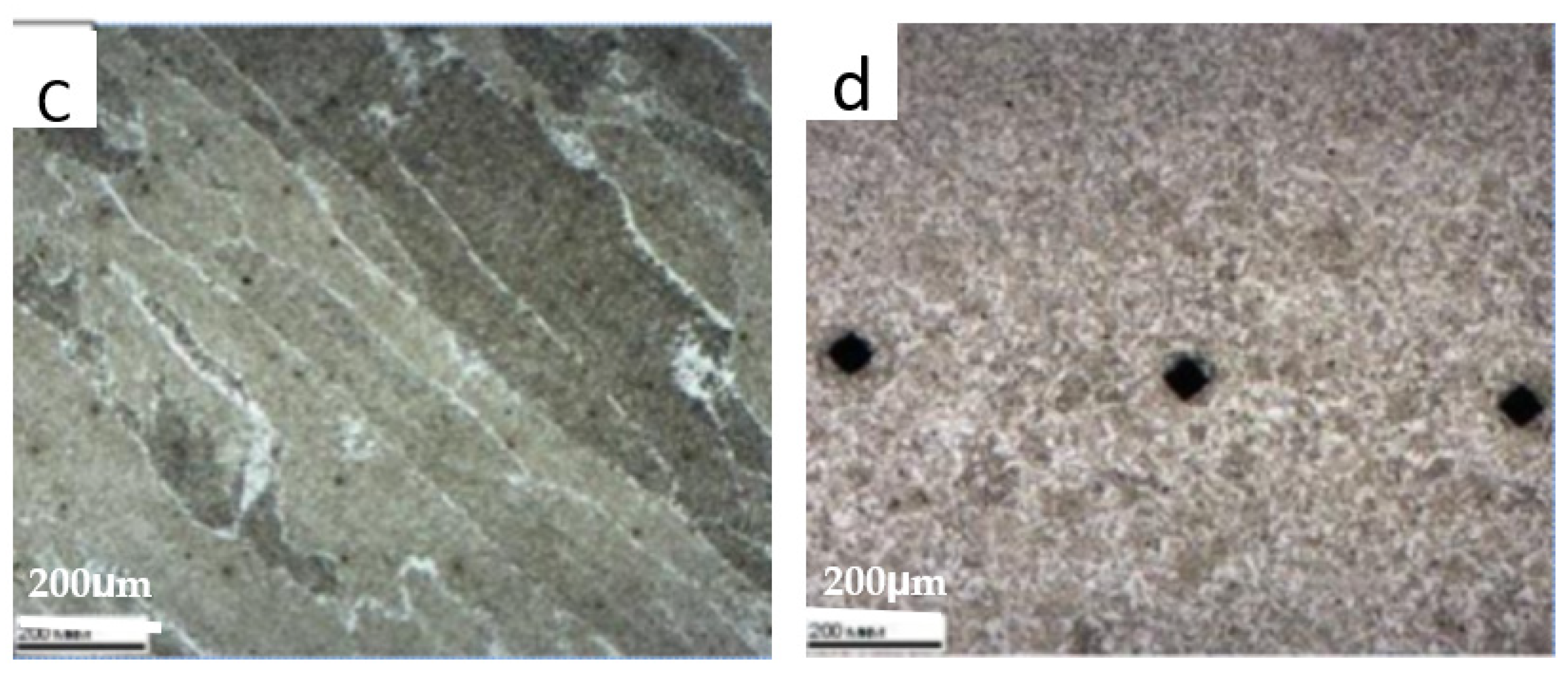
3.4. HAZ Microstructure

Large areas occupied by degenerate perlite were observed, with small perlite grains (diameters of several microns). In addition to degenerate perlite, cementite was observed along the boundaries of ferrite grains. Carbonitrides were observed in all parts of the sample, but their concentration fluctuated significantly in different areas. The carbonitride particles varied in size from 3–6 nm to 30–50 nm. A characteristic feature of the microdiffraction patterns of the carbonitrides is peak splitting (see Figure 9a). The reflected peaks form closely spaced pairs of subpeaks, one of which (near the zero beam) corresponds to larger interplanar spacing, and the other to smaller spacing. Such peak splitting can be explained by the inhomogeneous composition of particles, containing predominantly titanium in one layer and niobium in the other. The interplanar spacings for pairs of carbonitride peaks in Figure 9a were calculated using the ferrite (200) peaks to calibrate the intensity. The obtained interplanar spacings of 0.215 and 0.222 nm correspond to the tabulated values for the TiC (200) plane and NbC (200) plane, respectively, which confirms that the particles had a (Ti,Nb)C composition.
For a more detailed study of these particles, foils were investigated using transmission electron microscopy, and an image of the particles is shown in Figure 9b. Elemental mapping was performed at the three points shown in the image, and the corresponding results from the three spectra are shown in Table 3. The particles were found to contain significant amounts of Ti and Nb. In addition, oxygen was identified in the inclusion, suggesting the presence of an oxide substrate on which titanium and niobium carbides settled. As shown in Figure 9b, spectrum 1 identified both Ti and Nb, with higher content of Nb than Ti. In contrast, spectrum 3 (matrix area) identified no Mg, Ti, or Nb.

4. Conclusions

Microalloying of the seam metal with Ti, B, and Al in certain combinations contributed to the formation of acicular ferrite. Furthermore, compared with the matrix, the boundaries of the ferrite grains were less uniform and the dislocation density was higher in the HAZ. The TEM analyses identified an oxide component in the carbonitride particles, which is attributed to nanoscale corrosive–aggressive non-metallic inclusions that act as a substrate for the deposition of titanium and niobium carbides [22,23,24,25]. Such complex precipitates can lead to an additional reduction in the corrosion resistance of the metal in the HAZ [26]. Cooling down the HAZs at high rates seems to make them intrinsically less likely to corrode, but also less able to form effective passive films that could protect the corroding surfaces in the long run [27]. In steel, an increased level of corrosive–aggressive non-metallic inclusions can intensify local corrosion processes in the base metal and HAZ. Nanoscale corrosive–aggressive non-metallic inclusions and complex precipitates consisting of oxide and carbonitride components can further decrease the corrosion resistance of the metal in the HAZ [28]. The corrosion behavior in the heat-affected zone (HAZ) was quite different from that in the weld metal (WM) and base metal (BM). The HAZ was an active region that could be preferentially and more quickly corroded [29]. To improve the corrosion potential of the HAZ and weld, it is necessary to use high-Ni welding materials. The results show that the WM produced by a Ni-containing flux-cored arc welding material exhibited lower H diffusion and a higher density of relatively strong high-angle grain boundary trap sites (irreversible H traps), indicating that the WM is more resistant to hydrogen-containing environments and could be suitable for hydrogen applications [30].
(1)
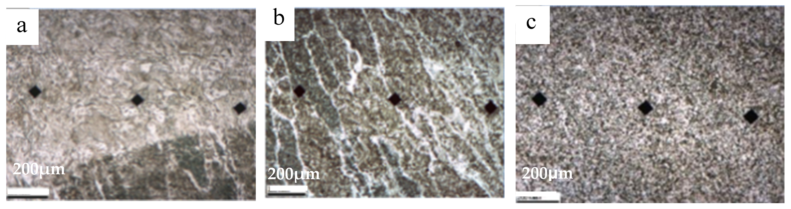
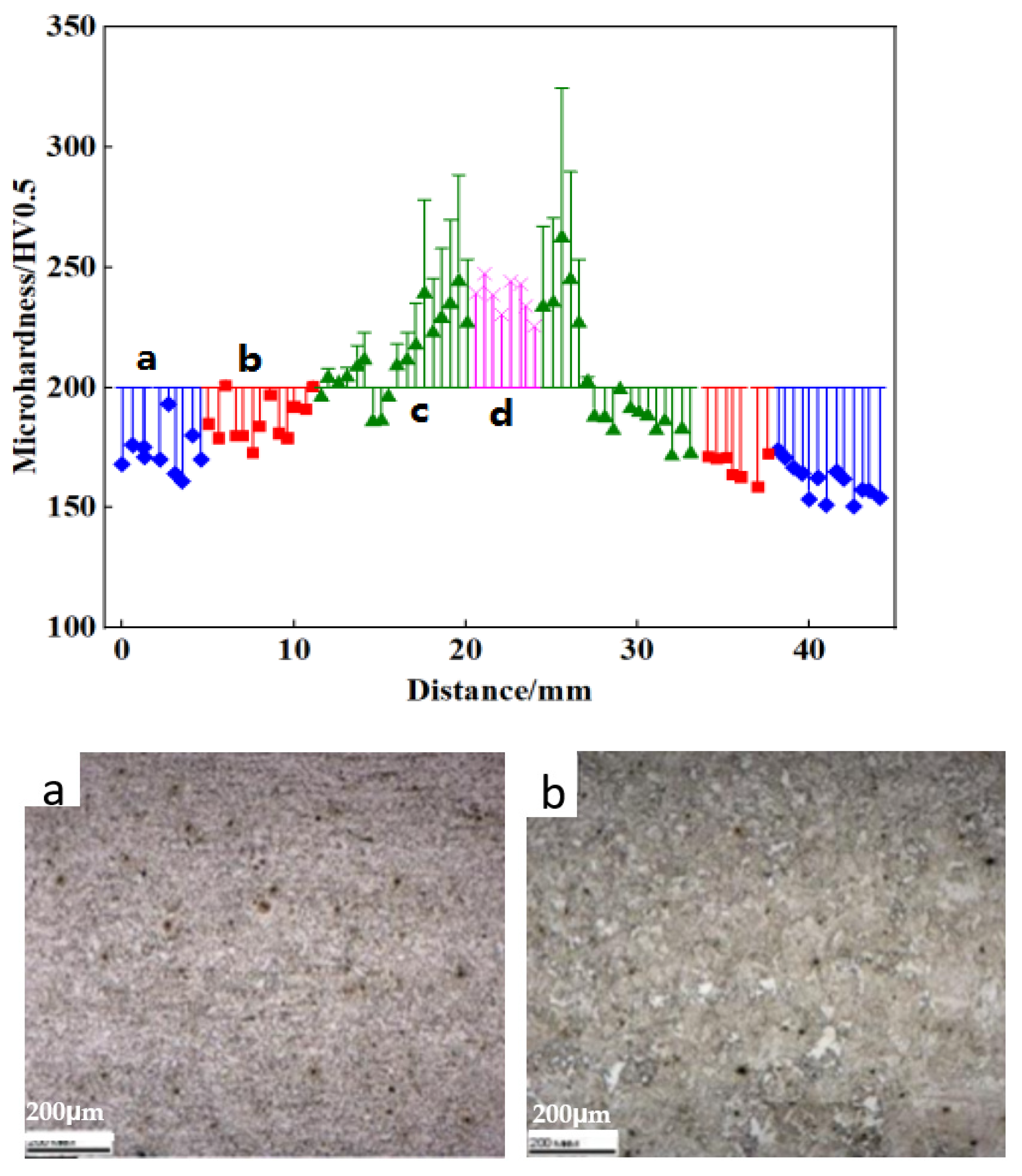
The microhardness distribution of welded joints was compared. The microhardness of Steel A increased in the weld area, reaching a maximum value of 230 HV near the fusion line characterized by a bainitic structure. The microhardness of the welded seam of Steel B increased from 170 HV in the base metal to 240 HV in the middle of the seam. The maximum microhardness was measured in the recrystallization area.
(2)
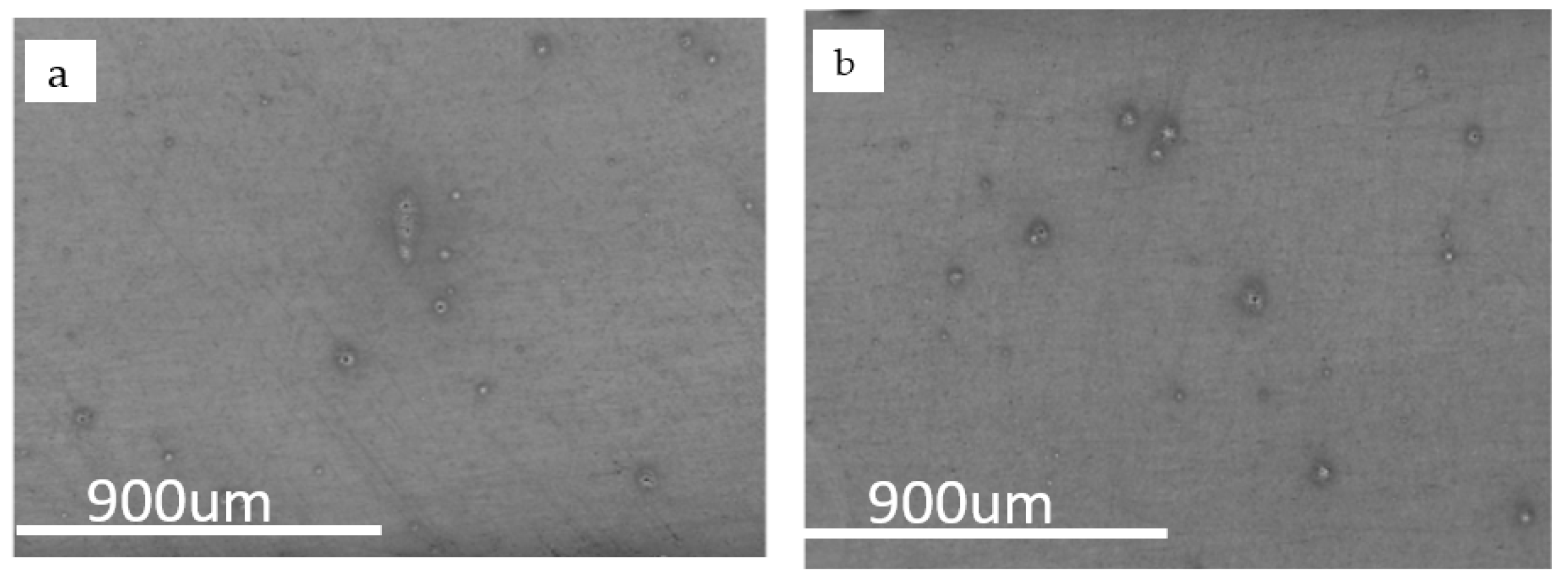
The corrosion rate of the matrix was higher than that of other parts of the weld, due to the presence of corrosive non-metallic inclusions in the substrate. The average corrosion rates of Steels A and B were 0.85 and 1.19 mm/year in the HAZ, respectively. The serious corrosion was due to the lower free corrosion potential.
(3)
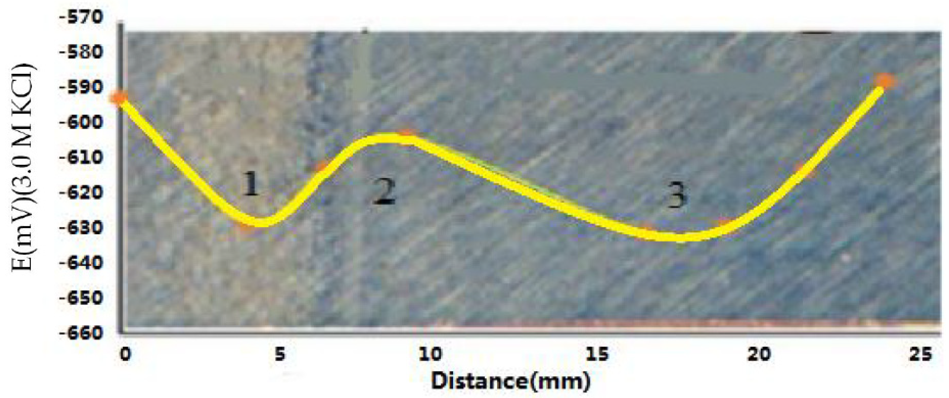
The free corrosion potentials of different parts of the welds were measured. The free corrosion potential difference of the adjacent area of Steel B was more than 40 mV, which implied a significant electrochemical difference that reduced the corrosion resistance. In contrast, the potential difference of Steel A was small. The recrystallization area had the highest microhardness, and local corrosion defects occurred due to recrystallization. The weld fusion line had the lowest free corrosion potential due to the precipitation of sub-micron ions.
(4)
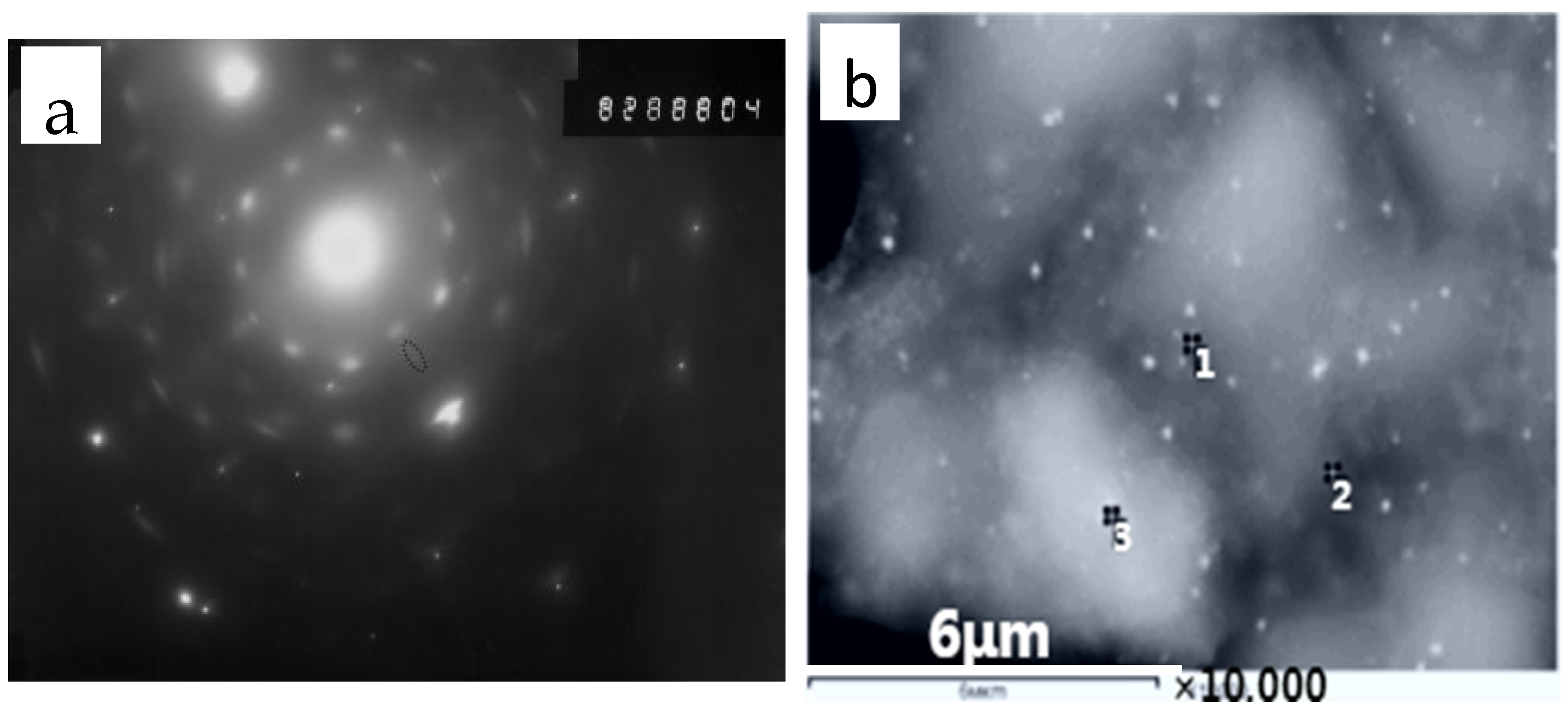
EDS and XRD analyses of the precipitates identified Mg, Si, and Ca oxide components in addition to Ti and Nb carbonitrides. Nanometer non-metallic inclusions were observed in the matrix, which was coated with precipitates of Ti and Nb carbonitrides. Such composite precipitates may further reduce the corrosion resistance in the HAZ.

Author Contributions

Conceptualization, M.L. and H.W.; methodology, H.W. and Y.S.; software, H.W.; validation, H.W. and Y.S.; formal analysis, M.L.; investigation, M.L.; resources, M.L.; data curation, H.W. and Y.S.; writing—original draft preparation, M.L.; writing—review and editing, H.W. and Y.S.; visualization, M.L.; supervision, Y.S.; project administration, M.L.; funding acquisition, M.L.; All authors approved the published version and agreed to be responsible for the work. All authors have read and agreed to the published version of the manuscript.

Funding

This research received no external funding.

Data Availability Statement

Not applicable.

Conflicts of Interest

The authors declare no conflict of interest.

References

  1. Li, M.; Wu, H.; Sun, Y. Effect of the inclusion features on mechanical properties of steel. Ironmak. Steelmak. 2021, 49, 405–411. [Google Scholar] [CrossRef]
  2. Hoar, T.P. Corrosion Control at Welded Joints in Constructional Steels. Br. Corros. J. 1967, 2, 46–48. [Google Scholar] [CrossRef]
  3. Baker, R.G.; Whitman, J.G. Practical Corrosion Problems in Relation to Welded Joints. I. Special Characteristics of the Welding Process Which can Cause Corrosion Problems. Brit. Corros. J. 1967, 2, 34–40. [Google Scholar] [CrossRef]
  4. Xu, S.; Wang, H.; Li, A.; Wang, Y.; Su, L. Effects of corrosion on surface characterization and mechanical properties of butt-welded joints. J. Constr. Steel Res. 2016, 126, 50–62. [Google Scholar] [CrossRef]
  5. Li, M.; Li, W.Y.; Yang, X.W.; Alexopoulos, N.D. Corrosion performance and mechanical properties of friction stir welded AA2024-T3 joints under different corrosion solution exposure. Mater. Corros. 2017, 68, 970–976. [Google Scholar] [CrossRef]
  6. Sinhmar, S.; Dwivedi, D. Enhancement of mechanical properties and corrosion resistance of friction stir welded joint of AA2014 using water cooling. Mater. Sci. Eng. A 2017, 684, 413–422. [Google Scholar] [CrossRef]
  7. Qi, K.; Li, R.; Wang, G.; Li, G.; Liu, B.; Wu, M. Microstructure and Corrosion Properties of Laser-Welded SAF 2507 Super Duplex Stainless Steel Joints. J. Mater. Eng. Perform. 2018, 28, 287–295. [Google Scholar] [CrossRef]
  8. Bai, D.; Liu, F.; Zhang, H.; Liu, J. Study on corrosion behavior of high nitrogen steel welded joint assisted by ultrasonic vibration. Mater. Lett. 2022, 317, 132101. [Google Scholar] [CrossRef]
  9. Cheng, M.; He, P.; Lei, L.; Tan, X.; Wang, X.; Sun, Y.; Li, J.; Jiang, Y. Comparative studies on microstructure evolution and corrosion resistance of 304 and a newly developed high Mn and N austenitic stainless steel welded joints. Corros. Sci. 2021, 183, 109338. [Google Scholar] [CrossRef]
  10. Wang, J.F.; Ma, J.K.; Liu, Y.; Zhang, T.; Wu, S.; Sun, Q. Influence of Heat Input on Microstructure and Corrosion Resistance of Underwater Wet-Welded E40 Steel Joints. J. Mater. Eng. Perform. 2020, 29, 6987–6996. [Google Scholar] [CrossRef]
  11. Bocchi, S.; Cabrini, M.; D’urso, G.; Giardini, C.; Lorenzi, S.; Pastore, T. The influence of process parameters on mechanical properties and corrosion behavior of friction stir welded aluminum joints. J. Manuf. Process. 2018, 35, 1–15. [Google Scholar] [CrossRef]
  12. Huang, Y.; Huang, J.; Zhang, J.; Yu, X.; Li, Q.; Wang, Z.; Fan, D. Microstructure and corrosion characterization of weld metal in stainless steel and low carbon steel joint under different heat input. Mater. Today Commun. 2021, 29, 102948. [Google Scholar] [CrossRef]
  13. Wu, W.; Hu, S.; Shen, J. Microstructure, mechanical properties and corrosion behavior of laser welded dissimilar joints between ferritic stainless steel and carbon steel. Mater. Des. 2015, 65, 855–861. [Google Scholar] [CrossRef]
  14. Montes, O.F.; Garcés, R.S.; Reyes, F.A.R.; Robledo, P.d.C.Z.; López, F.H.E.; Calderón, F.A. Behaviour on corrosion of API X70 steel welded using the process of double submerged arc welding immersed in corrosive media. Weld. Int. 2018, 32, 651–659. [Google Scholar] [CrossRef]
  15. Li, M.; Wu, H.; Sun, Y. Influence of Non-metallic Inclusions on Corrosive Properties of Polar Steel. Front. Mater. 2021, 8, 602851. [Google Scholar] [CrossRef]
  16. Yan, Y.; Deng, H.; Xiao, W.; Ou, T.; Cao, X. Corrosion behaviour of X80 pipeline steel welded joint in H2O-saturated supercritical-CO2 environment. Int. J. Electrochem. Sci. 2020, 15, 1713–1726. [Google Scholar] [CrossRef]
  17. Ma, H.; Liu, Z.; Du, C.; Wang, H.; Li, X.; Zhang, D.; Cui, Z. Stress corrosion cracking of E690 steel as a welded joint in a simulated marine atmosphere containing sulphur dioxide. Corros. Sci. 2015, 100, 627–641. [Google Scholar] [CrossRef]
  18. Song, J.; Li, Z.; Xiao, K.; Luo, H.; Chen, J.; Yu, W.; Zhang, X.; Dong, C. Study on the local corrosion behaviour and mechanism of bogie steel welded joints. Corros. Sci. 2022, 208, 110709. [Google Scholar] [CrossRef]
  19. Rajesh, S.; Badheka, V. Influence of heat input/multiple passes and post weld heat treatment on strength electrochemical characteristics of friction stir weld joint. Mater. Manuf. Process. 2018, 33, 156–164. [Google Scholar] [CrossRef]
  20. Gu, Y.; Lu, N.; Xu, Y.; Shi, Y.; Zhang, G.; Sun, Q. Microstructure characteristics of Q345R-steel welded joints and their corrosion behavior in a hydrofluoric acid environment. J. Nucl. Mater. 2023, 574, 154214. [Google Scholar] [CrossRef]
  21. Dou, X.; He, Z.; Zhang, X.; Liu, Y.; Liu, R.; Tan, Z.; Zhang, D.; Li, Y. Corrosion behavior and mechanism of X80 pipeline steel welded joints under high shear flow fields. Colloids Surf. A Physicochem. Eng. Asp. 2023, 665, 131225. [Google Scholar] [CrossRef]
  22. Rodionova, I.G.; Baklanova, O.N.; Filippov, G.A.; Reformatskaya, I.I.; Podobaev, A.N.; Zinchenko, S.D.; Filatov, M.V.; Efimov, S.V.; Tishkov, Y.V.; Golovanov, A.V.; et al. The role of non-metallic inclusions in accelerating the local corrosion of metal products made of plain-carbon and low-alloy steels. Metallurgist 2005, 49, 125–130. [Google Scholar] [CrossRef]
  23. Rodionova, I.G.; Baklanova, O.N.; Zaitsev, A.I. On the role of non-metallic inclusions in the acceleration of local corrosion of oil-field pipelines made of carbon and low-alloy steels. Russ. Metall. 2004, 5, 13–18. [Google Scholar]
  24. Li, H.; Qiao, J.; Jiang, X.; Chen, J.; Wu, Y. Tissue and corrosion properties of laser welded joints of high strength steel. Trans. China Weld. Instit. 2015, 36, 75–78. [Google Scholar]
  25. Li, Y.; Yang, M.; Huang, S.; Wu, K. Study on corrosion resistance of X90 pipeline steel welded joint. Electric Weld. Mach. 2017, 47, 37–42. [Google Scholar]
  26. Zinchenko, S.D.; Lamukhin, A.M.; Filatov, M.; Efimov, S.; Rodionova, I.; Zaitsev, A.; Baklanova, O. Development of recommendations on making tube steels produced at the severstal combine cleaner with respect to corrosion-active non-metallic inclusions. Metallurgist 2005, 4, 131–137. [Google Scholar] [CrossRef]
  27. Eliyan, F.F.; Alfantazi, A. Effect of bicarbonate concentration on corrosion of high strength steel. Corros. Eng. Sci. Technol. 2014, 50, 178–185. [Google Scholar] [CrossRef]
  28. Wang, J.; Guo, P.; Wang, X.; Di, H.; Zhao, Y. Study on microstructure and corrosion resistance of laser welded joint of X100 pipeline steel. Appl. Laser 2017, 37, 835–840. [Google Scholar]
  29. Yan, M.; Wei, B.; Xu, J.; Li, Y.; Hu, Y.; Cai, Z.; Sun, C. Insight into sulfate-reducing bacteria corrosion behavior of X80 pipeline steel welded joint in a soil solution. J. Mater. Res. Technol. 2023, 24, 5839–5863. [Google Scholar] [CrossRef]
  30. Moshtaghi, M.; Loder, B.; Safyari, M.; Willidal, T.; Hojo, T.; Mori, G. Hydrogen trapping and desorption affected by ferrite grain boundary types in shielded metal and flux-cored arc weldments with Ni addition. Int. J. Hydrogen Energy 2022, 47, 20676–20683. [Google Scholar] [CrossRef]
Figure 1. Schematic diagram of the welding groove.
Metals 13 01528 g001
Figure 2. Schematic of the electrochemical test setup.
Metals 13 01528 g002
Figure 3. Macrostructures of the welded joints of steel (A,B).
Metals 13 01528 g003
Figure 4. Microhardness and the corresponding microstructure of the first welded seam on Steel A: (a) near-weld area, (b) area with columnar crystals, and (c) recrystallization area.
Metals 13 01528 g004aMetals 13 01528 g004b
Figure 5. Microhardness and the corresponding microstructure of the first welded seam of Steel B: (a) base metal, (b) HAZ, (c) area containing columnar crystals, and (d) recrystallization area.
Metals 13 01528 g005aMetals 13 01528 g005b
Figure 6. Macrostructure of the investigated steel samples at 70 magnification: Steel A (a) and Steel B (b).
Metals 13 01528 g006
Figure 7. Free corrosion potential versus distance along the weld joint of Steel A: (1) near-weld area, (2) area with columnar crystals, and (3) recrystallization area.
Metals 13 01528 g007
Figure 8. Free corrosion potential versus distance along the weld joint of Steel B: (1) base metal, (2) HAZ, (3) area with columnar crystals, and (4) recrystallization area.
Metals 13 01528 g008
Figure 9. (a) Diffraction pattern from a nanosized carbonitride particle in the HAZ and (b) a TEM image showing the non-uniform composition of carbonitride particles.
Metals 13 01528 g009
Table 1. Chemical composition of the steel plates (wt%).
SampleCMnSiSPCrTiNbAl
A0.061.480.180.0020.0120.150.0050.0120.042
B0.121.560.240.0030.0160.110.0130.0360.018
Table 2. Results of corrosion tests in a moving corrosive environment of welded seams.
SampleAverage Depth of Corrosion, mmAverage Corrosion Rate, mm/year
Base MetalHAZSeam MetalBase MetalHAZSeam Metal
A0.0320.0230.0341.160.851.23
B0.0450.0330.0301.641.191.10
Table 3. Elemental compositions obtained from the points shown in the TEM image in Figure 9b.
SpectrumCOMgAlSiCaTiMnFeNb
120.5112.420.001.190.420.360.391.1260.812.15
241.6813.820.000.971.350.220.000.8938.461.69
317.199.270.451.460.550.220.001.4068.510.00
Disclaimer/Publisher’s Note: The statements, opinions and data contained in all publications are solely those of the individual author(s) and contributor(s) and not of MDPI and/or the editor(s). MDPI and/or the editor(s) disclaim responsibility for any injury to people or property resulting from any ideas, methods, instructions or products referred to in the content.

