Article

Study on Joining for Thin-Walled Aluminum Alloy/Steel Tubes by Electromagnetic Flanging Process

1
State Key Laboratory of Advanced Design and Manufacturing Technology for Vehicle, Hunan University, Changsha 410082, China
2
School of Mechanical and Electrical Engineering, Hunan City University, Yiyang 413000, China
3
Shenzhen Automotive Research Institute (Shenzhen Research Institute of National Engineering Laboratory for Electric Vehicles), Shenzhen 518118, China
*
Author to whom correspondence should be addressed.
Metals 2023, 13(9), 1529; https://doi.org/10.3390/met13091529
Submission received: 3 July 2023 / Revised: 23 August 2023 / Accepted: 27 August 2023 / Published: 29 August 2023
(This article belongs to the Section Welding and Joining)

Abstract

:
A structure for joining thin-walled 6061-T6 aluminum alloy tube (outer tube) and Q195 steel tube (inner tube) by electromagnetic flanging process was proposed. The formation process, mechanical properties, failure modes, and morphology of the joint were investigated. The results showed that the outer tube impacted the inner tube, the flanges of the prefabricated holes on the outer tube were embedded into the prefabricated holes of the inner tube under the action of Lorentz force, and thus the mechanical locking joint was obtained. There were two tensile failure modes for the joints: Pull-out and fracture. Specifically, when the discharge energy was relatively high, the failure mode changed from pull-out to fracture. Combining the results of tensile tests and morphology observations, the maximum loads of the joints increased with the discharge energy. However, excessive discharge energy would lead to the brittle fracture of the inner tube, which was not beneficial to the service. Better discharge energy and the maximum load of the joint at this discharge energy were obtained.

1. Introduction

Currently, the development of the vehicle industry is facing great pressure from energy and the environment [1,2]. According to relevant research, each 10% reduction in the weight of a vehicle will reduce fuel consumption by 8% and emissions by 4%. Therefore, lightweight vehicles have become an important way to save energy and reduce emissions [3,4,5,6]. For new energy vehicles, the weight also affects the cruising range and performance directly, and the demand for lightweight vehicles is more urgent. It is an important means to use aluminum alloys to partially replace steel to achieve the goal of lightweight vehicles, but the problem of joining aluminum alloys and steel needs to be solved [7,8].
Joining-by-forming is a process of obtaining a joint through the plastic deformation of at least one joining component. There are many advantages of the joining-by-forming process, such as high joint strength, simple structure, low cost, high productivity, and wide applicability. It has great prospects in the field of manufacturing, which is especially suitable for the joining between dissimilar materials [9,10]. Traditional joining-by-forming processes include clinching, hemming, riveting, extrusion, forging, hydroforming, rolling, swaging, and spinning [11,12,13,14,15,16]. However, due to the relatively poor formability of aluminum alloys at room temperature, it is easy to crack when forming by the traditional process. Electromagnetic forming (EMF) could generate high strain rates of aluminum alloys by Lorentz force, which increases its forming limit at room temperature greatly, which improves the quality of forming and joining [17,18,19].
EMF has been widely used to join aluminum alloys and other materials in many fields. Park et al. [20] designed the axial joint and torque joint of joining by EMF between 6063-T5 aluminum alloy tubes and high-strength steel tubes. They analyzed the stress and deformation of an aluminum alloy tube and studied the influence of groove parameters on the mechanical properties of the joints. Furthermore, the guidelines for designing the joint by EMF were established. Areda et al. [21] joined 1050 aluminum alloy tubes and 4340 steel rods by EMF. The effects of discharge energy on the effective plastic strain, deformation velocity, displacement, Lorentz force, current density, magnetic induction intensity, and maximum shear stress were predicted, and the optimal discharge energy was found. Kumar et al. [22] used EMF to join 1050 aluminum alloy tubes onto 1020 steel rods and analyzed the strength and microstructure of the joints with the change in profile of the steel rod. The results showed that the threaded profile provided higher strength than the plain and knurled profiles, and there was no gap between the joining components at the appropriate discharge energy. Rajak et al. [23] obtained the joints between aluminum connector terminals and copper wires by EMF. It was found that in the gap between the aluminum connector terminal and copper wire, the resistance was reduced compared to the traditional process. The pull-out force, surface roughness, and hardness of the joints were improved. Weddelling et al. [24] joined extruded aluminum alloy tubes and mandrels by EMF and analyzed the influence of the groove shape on joint strength. The joints formed by the rectangular groove and circular groove were stronger than those formed by the triangular groove with the same size. Interference stresses at the tube/mandrel interface were generated with the increase in charging energy, which increased the pull-out strength. Chen et al. [25] studied the joining between large-diameter 6061-T6 aluminum alloy tubes and AZ31B magnesium alloy shafts through EMF by numerical simulation and experiments. Two failure modes of the joint, torsional separation and torsional crack, were found, and the maximum torque at better process parameters was obtained.
As a form of EMF, the electromagnetic flanging process has also been studied by scholars. Jimbert et al. [26] investigated a two-step electromagnetic flanging process for AA6016-T4 aluminum alloy sheets and quantified the process window considering the variation of maximum allowable overlap with component radius. This process window was applied to determine the process dimensions of complex components. Chu et al. [27] analyzed the possibility of electromagnetic flanging blank design and process design for AA6061-T6 aluminum alloy sheets and studied the changes in electromagnetic parameters during the flanging process. The results showed that the deformation of the workpieces had a significant influence on the electromagnetic force, and the flanging quality of preformed workpieces was better. Deng et al. [28] established a fracture model of electromagnetic flanging for AA5052 aluminum alloy sheets using the high-speed Digital Image Correlation system and verified its effectiveness by the experiments. The model combined the uncoupled fracture model, the Gissmo damage evolution model, and the Johnson–Cook strain rate effect. However, the application of electromagnetic flanging in joining thin-walled tubes is still rare. There are a large number of thin-walled structural components in the lightweight design and manufacturing of vehicles, among which the thin-walled tube components account for a considerable proportion, such as the transmission shaft, seat frame, and car cross beam (CCB). With the popularization of the space frame vehicle body, thin-walled tubes have become increasingly important in vehicles. In this work, a structure was proposed for joining thin-walled aluminum alloy and steel tubes by the electromagnetic flanging process. The formation process, mechanical properties, failure modes, and morphology of the joints were studied. First, the LS-DYNA® was used for numerical simulation, and the accuracy of the model was verified. Subsequently, the tensile tests were performed after the experiments of joining by electromagnetic flanging, and the failure modes were analyzed. Finally, the morphology of the joints was observed, and the relationships between it and the mechanical behaviors were discussed. This work could provide a new reference for the lightweight design and manufacture of vehicles.

2. Materials and Methods

2.1. Materials Preparation

A 6061-T6 aluminum alloy tube and a Q195 steel tube were used, and the element compositions and the mechanical properties of the two materials are shown in Table 1 and Table 2. The length, outer diameter, and inner diameter of the aluminum alloy tube are 162 mm, 30 mm, and 27.8 mm. The length, outer diameter, and inner diameter of the steel tube are 162 mm, 28 mm, and 25.9 mm. There were four evenly distributed prefabricated holes located 28 mm away from one end of both of the two tubes. The diameter of the prefabricated holes on the aluminum alloy tube is 8 mm, and the diameter of the prefabricated holes on the steel tube is 13 mm. For ease of assembly and positioning, there was a positioning hole located 10 mm away from the other end of both tubes. The angle between the central axis of the positioning hole and the central axis of the one of prefabricated holes is 135°. At the end of the steel tube with prefabricated holes, it was turned into a step with an outer diameter of 27.4 mm and a length of 56 mm. The specimens were polished with fine sandpaper, and then cleaned with ultrasonic wave for 5 min and assembled after drying. Figure 1 shows the structural assembly and dimensional parameters, where the aluminum alloy tube is the outer part of the joint and the steel tube is the inner part of the joint.

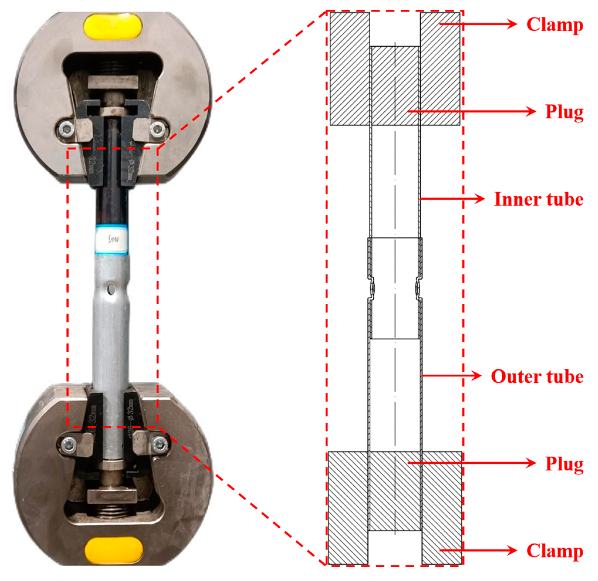
2.2. Experiments of Joining by Electromagnetic Flanging

Figure 2a shows the electromagnetic system (EMS) in this work, which includes the control cabinet, capacitor cabinet, and cable. The EMS needs to be used with tools together, which mainly include a coil, field shaper, slider, and chute, as shown in Figure 2b. Before discharging, the inner and outer tubes are fixed on the sliders by pins and positioning holes. Moving the sliders on the chutes makes the prefabricated holes on the inner and outer tubes concentric and they are located in the working area of the field shaper. Then the bolt is locked to fix the processing position. When the EMS discharges, the high-frequency attenuating oscillating currents flow into the coil through the cable, generating a transient strong magnetic field. There are induced currents on the field shaper under the influence of this transient strong magnetic field, resulting in secondary induced currents on the outer tube, which causes the outer tube to move away from the field shaper at a high velocity driven by the Lorentz force. When the outer tube impacts the inner tube, the flanges of the prefabricated holes on the outer tube embed into the prefabricated holes of the inner tube, so as to obtain a mechanically locked joint. Figure 3 shows the joining process for the joint. In this work, the discharge energies of 14 kJ, 15 kJ, 16 kJ, 17 kJ, 18 kJ, and 19 kJ were selected for the experiments, and each experiment was repeated thrice to ensure its reliability.

2.3. Test Methods

Figure 4 shows the tensile test, which was conducted on the LABSANS LD 26.105 universal testing machine at the tensile speed of 2 mm/min. The test standard is GB/T 228.1-2021 Metallic materials-Tensile testing-Part 1: Method of test at room temperature [29]. The ends of both the inner and outer tubes were supported by steel plugs to prevent deformation and slipping. The micro-morphology of the joints and fracture was observed on an Olympus DSX1000 digital microscope (Olympus, Tokyo, Japan) and a Carl Zeiss Σ IGMA HD field emission scanning electron microscope (Carl Zeiss AG, Jena, Germany).

3. Numerical Simulation

3.1. Numerical Model

In the electromagnetic flanging process, the tubes produce severe plastic deformation in an extremely short period of time, and it is difficult to observe the electromagnetic and mechanical characteristics of the tubes. The numerical simulation with sequential coupling of the Finite Element Method (FEM) and the Boundary Element Method (BEM) could solve this problem well [30,31]. The simplified coupling model of the electromagnetic field and mechanical field was established in the commercial software LS-DYNA® (V9.71 R7.0, LSTC, Livermore, CA, USA) in this study, as shown in Table 3 and Figure 5.
The strain, strain rate, temperature, and stress of the material change when subjected to dynamic load, and the Johnson–Cook (J-C) model could characterize the constitutive relationship of the material in this case [32]. The J-C model could be described by an equation:
δ = A + B ε n 1 + C ln ε ˙ ε ˙ 0 1 T T r T m e l t T r m
where Tr are Tmelt are the reference temperature and melting temperature, respectively. Due to the instantaneous completion of the electromagnetic flanging process, there is almost no temperature change, so the temperature correction part in the J-C model is ignored. The simplified J-C model can be described by an equation:
δ = A + B ε n 1 + C ln ε ˙ ε ˙ 0
where δ, ε, ε ˙ , and ε ˙ 0 are the equivalent yield stress, the equivalent plastic strain, the effective plastic strain rate, and the reference plastic strain rate, respectively. A, B, C, n, and m are the yield stress at the reference strain rate and the reference temperature, the strain strengthening coefficient, the strain rate sensitivity coefficient, the strain hardening coefficient, and the temperature sensitivity coefficient, respectively. The J-C model parameters and material parameters were cited from references [33,34,35,36,37], as shown in Table 4 and Table 5.
The time–current curve was obtained by the Rogowski coil, as shown in Figure 6, and the numerical simulation was conducted at the discharge energy of 18 kJ (9.393 kV). The maximum amplitude and the frequency of the curve were 166.8 kA and 12.721 kHz, respectively. The time–current curve was imported into the electromagnetic (EM) module of the LS-DYNA® as the exciting currents to drive the deformation of the outer tube.

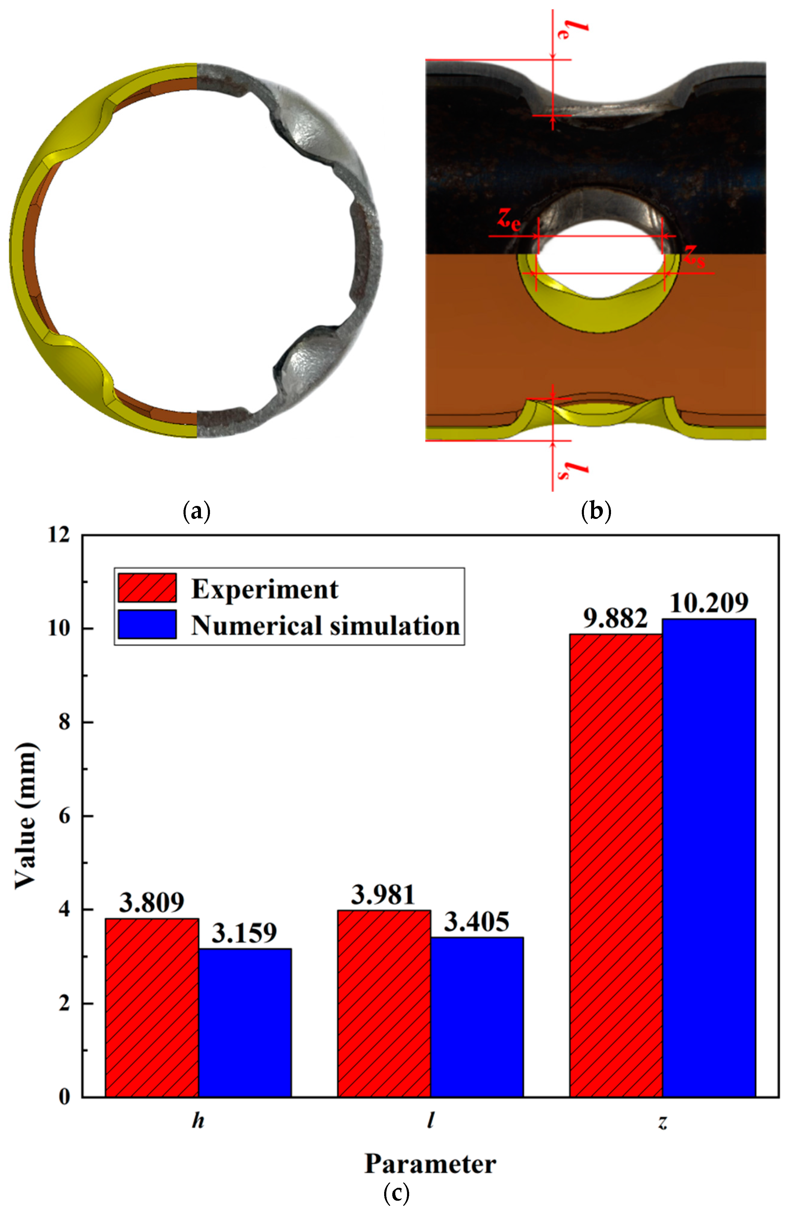
3.2. Verification of Model

In order to verify the accuracy of the electromagnetic flanging process in the model, the morphology of the cross-section and longitudinal section of the joint obtained by the experiment was compared with that of the numerical simulation, as shown in Figure 7a,b. It could be seen that their morphology was considerably consistent. The flanging height on the cross-section (he/hs), the flanging height on the longitudinal section (le/ls), and the length of the major semi-axis of the oval hole on the outer tube after flanging (ze/zs) were selected as the measurement objects in the experiment and numerical simulation, respectively. All of them were parameters that reflected the deformation of the components. Figure 7c shows the measured values of these parameters, in which the average values of he/hs, le/ls, and ze/zs were 3.809 mm/3.159 mm, 3.981 mm/3.405 mm, and 9.882 mm/10.209 mm, respectively, while the errors were only 17.06%, 14.47%, and 3.31%. It could be proven that the numerical model in the LS-DYNA® was reliable relatively.

4. Results and Discussion

4.1. Formation Process of the Joint

The formation process of the joints could be analyzed from the distribution of current density, distribution of Lorentz force, and deformation of the tubes via the numerical simulation. The entire duration of the numerical simulation was 30 μs, and Figure 8 shows the distribution of current density on the outer tube at the intermediate moment (t = 15 μs). It can be seen that the currents on the outer tube flowed in the circumferential direction, and they were mainly concentrated in the working area of the field shaper. The currents bifurcated at the prefabricated holes and accumulated at their axial ends due to the skin effect, so the current density was highest at these positions.
The intermediate moment (t = 15 μs) was also selected as the time to observe the distribution of Lorentz force on the outer tube, as shown in Figure 9. Due to the current densities at the axial ends of the prefabricated holes being much higher than those at other positions, the Lorentz force also exhibited the same distribution.
The longitudinal section and cross-section were selected to observe the deformation of the tubes, as shown in Figure 10, wherein the cross-section was located in the middle of the overlap zone between the inner and outer tubes. When the time was 00 μs, both the inner tube and outer tube were not deformed, and there was a slight gap between them due to the assembly. When the time was 20 μs, the outer tube in the influence range of the working area of the field shaper contracted inward and made contact with the inner tube due to the Lorentz force, and the gap disappeared. Because the Lorentz force on the axial ends of the prefabricated holes on the outer tube was larger than that on other positions, the deformation of the longitudinal section was greater than that of the cross-section too. When the time was 26 μs, the outer tube squeezed the inner tube continuously to deform it, while the flanges of the prefabricated holes on the outer tube flanged inward further and embedded into the prefabricated holes on the inner tube. When the time was 30 μs, the electromagnetic flanging process ended, and the tubes did not deform any further. The inner and outer tubes were joined mechanically by plastic deformation due to the uneven deformation of various positions, and the projection shape on the longitudinal section of the prefabricated holes on the outer tube was oval.

4.2. Mechanical Properties of the Joint

Table 6 shows the average maximum tensile loads and failure modes of the joints at different discharge energies. The Lorentz force increased with the discharge energy, thus the effect of mechanical locking was enhanced and the maximum tensile load of the joint also increased. The specific reason is explained further in the subsequent section “Morphology of the joint”. The failure mode is an important performance in determining the quality of the tubular joint [38]. There were two failure modes of the joint, as shown in Figure 11. Figure 11a shows the failure mode of pull-out, which was manifested as the outer tube (especially the part of the hole after flanging) deformed and then separated from the inner tube during the tensile process. Figure 11b shows the failure mode of fracture, which was manifested as the inner tube fractured during the tensile process.
Figure 12 shows the typical displacement–load curves of two failure modes. When the discharge energies were less than 18 kJ, the trends of the curves were generally consistent. Overall, the greater the discharge energies, the higher the strength of the joints. Specifically, the loads first increased and then decreased with the displacement. Subsequently, the loads increased again and then decreased, until they approached zero near the displacement of 24 mm, which indicated the complete separation of the inner tubes and outer tubes. When the discharge energy was 19 kJ, the load dropped to zero sharply after the joint was elongated by approximately 2 mm, and the inner tube was fractured. The maximum load of the joint at the discharge energy of 18 kJ was just 1.38% lower than that of 19 kJ (just lower by 123.07 N). However, the elongation of the joint before complete failure at the discharge energy of 18 kJ was much greater than that of 19 kJ, so it was more reliable in service. Therefore, the better discharge energy was 18 kJ.
Figure 13 shows the process for the failure mode of pull-out. It was obvious that the joints resisted tension under the combined action of friction force and normal force. The friction force came from the inward contraction of the outer tube wall, and the normal force came from the inward flanging of the flanges of the prefabricated holes on the outer tube. As the tensile process progressed, the friction force increased gradually, and the flanges at the front end of the prefabricated holes on the outer tube also moved outward until they “recovered” completely. At this moment, the normal force disappeared, and the friction force also began to decrease due to the further separation of the inner and outer tubes. Subsequently, the flanges at the back end of the prefabricated holes on the outer tube touched the inner tube, and then they were torn slowly. At this stage, the normal force generated and disappeared again. This explained why the joint underwent another process of rise and fall for tensile load after the peak of it. Finally, the inner and outer tubes were separated completely.

4.3. Morphology of the Joint

Figure 14 shows the macro-morphology of the joints at the discharge energies of 18 kJ and 19 kJ. It could be observed that the flanges of the prefabricated hole on the outer tubes were thinned due to shearing, and the wall of the inner tubes was also thinned due to impact. The flanging height on the cross-section (ha/hb), the flanging height on the longitudinal section (lc/ld), the thicknesses in the impact zone of the inner tubes (da/db), and the thicknesses in the shearing zone of the outer tubes (sc/sd) were measured. The average values of ha/hb, lc/ld, and da/db, sc/sd were 3.878 mm/4.508 mm, 4.172 mm/4.617 mm, 1.007 mm/0.800 mm, and 1.006 mm/0.977 mm, respectively. With the increase in discharge energy, the values of h and l increased by 16.25% and 10.67%, respectively, and the values of d and s decreased by 20.56% and 2.88%, respectively. Generally, the mechanical locking effects of the joints were better due to the greater flanging height. Meanwhile, the squeeze from the outer tubes on the inner tubes was also stronger, resulting in a larger friction force of the joint during the tensile process. Therefore, the maximum tensile load increased with the discharge energy. Although the outer tubes underwent shearing and thickness reduction, the reduction was slight with the increase in discharge energy, and there was little effect on the change in strength. The thickness reduction of the inner tubes significantly increased with the discharge energy, and its strength increased but its toughness decreased due to the work hardening. In addition, because of the decrease in force area, the stress also increased during the tensile process. When the strength of the joints increased with the discharge energy to be greater than the stress of the thinned zone of the inner tubes, brittle fracture occurred in the inner tubes.
For the joining-by-forming process, the performance of the joints largely depended on the micro-morphology of the components after deformation. To study the mechanical properties of the joints further, the metallographic structures of the outer tubes were observed, as shown in Figure 15. Zone A did not deform and zone B underwent the flanging deformation. The metallographic structure of zone A was the original metallographic structure of the outer tube. The material deformation in zone B was very large, and the grains also deformed severely. Specifically, the grains near the prefabricated holes of the inner tubes changed shape from equiaxed to slender along the flanging direction. The material in this zone was subjected to work hardening, which improved the strength of the joint. Compared with the discharge energy of 18 kJ, when it was 19 kJ, the slenderness of the grains in Zone B of the outer tubes was greater, resulting in higher strength of the joint. However, the inner tube would fracture before the joint failed due to the excessive deformation.
Figure 16 shows the fracture micro-morphology of the inner tube observed by scanning electron microscopy at the discharge energy of 19 kJ. There were no massive dimples accumulated at the fracture surface, just a few small and shallow equiaxed dimples appeared in some zones, which indicated that micro-plastic deformation occurred at the fracture surface locally, but the overall performance of the fracture was brittle. This further explained why the tensile load of the joint at the discharge energy of 19 kJ in Figure 12 decreased to zero immediately after reaching the peak.

5. Conclusions

In this paper, the electromagnetic flanging process was proposed for joining a thin-walled 6061-T6 aluminum alloy tube and a Q195 steel tube. The formation process, mechanical properties, failure modes, and morphology of the joint were investigated by numerical simulation and experiments. The main conclusions are as follows:
  • The electromagnetic flanging process could obtain effective joints between the aluminum alloy tube and the steel tube, which was a manufacturing process with application prospects for thin-walled structural tube components of vehicles.
  • The formation process of the joint was analyzed through numerical simulation. Because of the uneven distribution of the induced current density and Lorentz force, the deformation of flanges of the prefabricated holes on the outer tubes at the axial ends was greater than that at other positions. Therefore, their projection shape on the longitudinal section was oval.
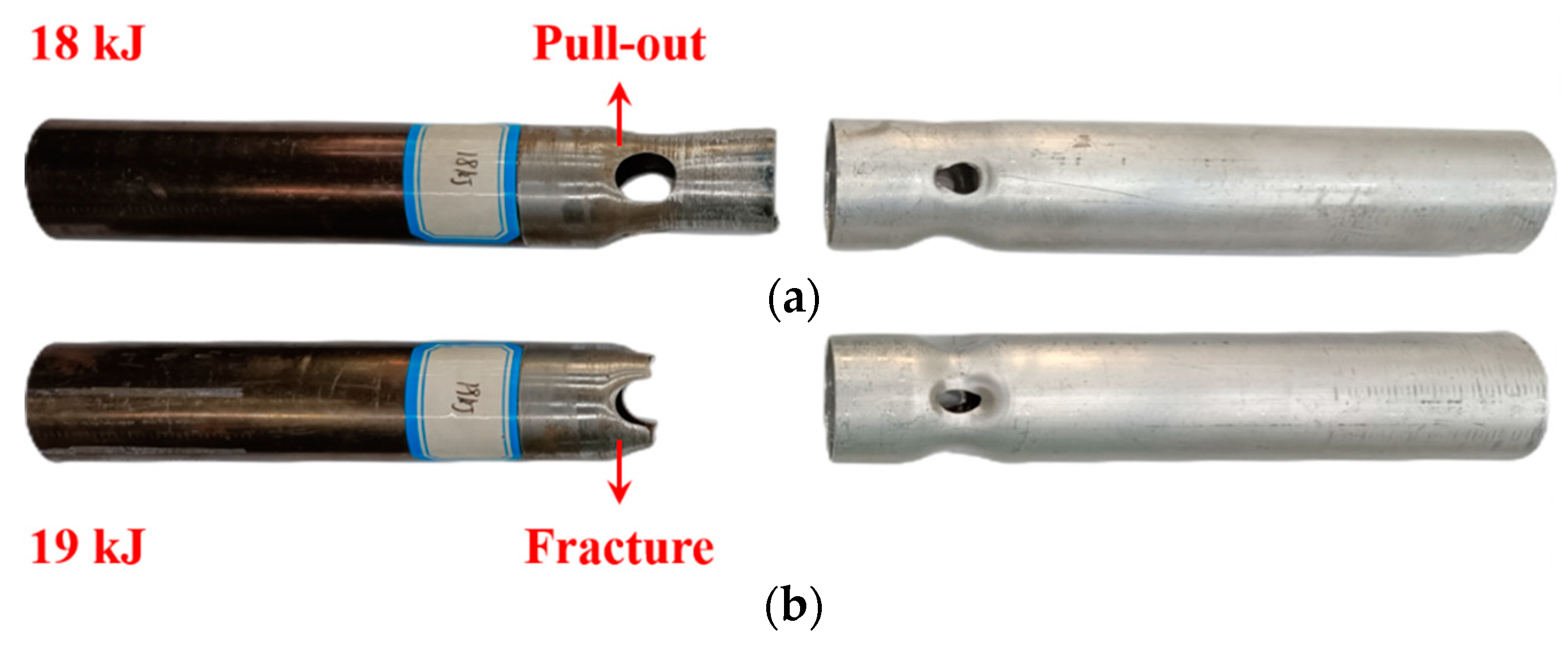
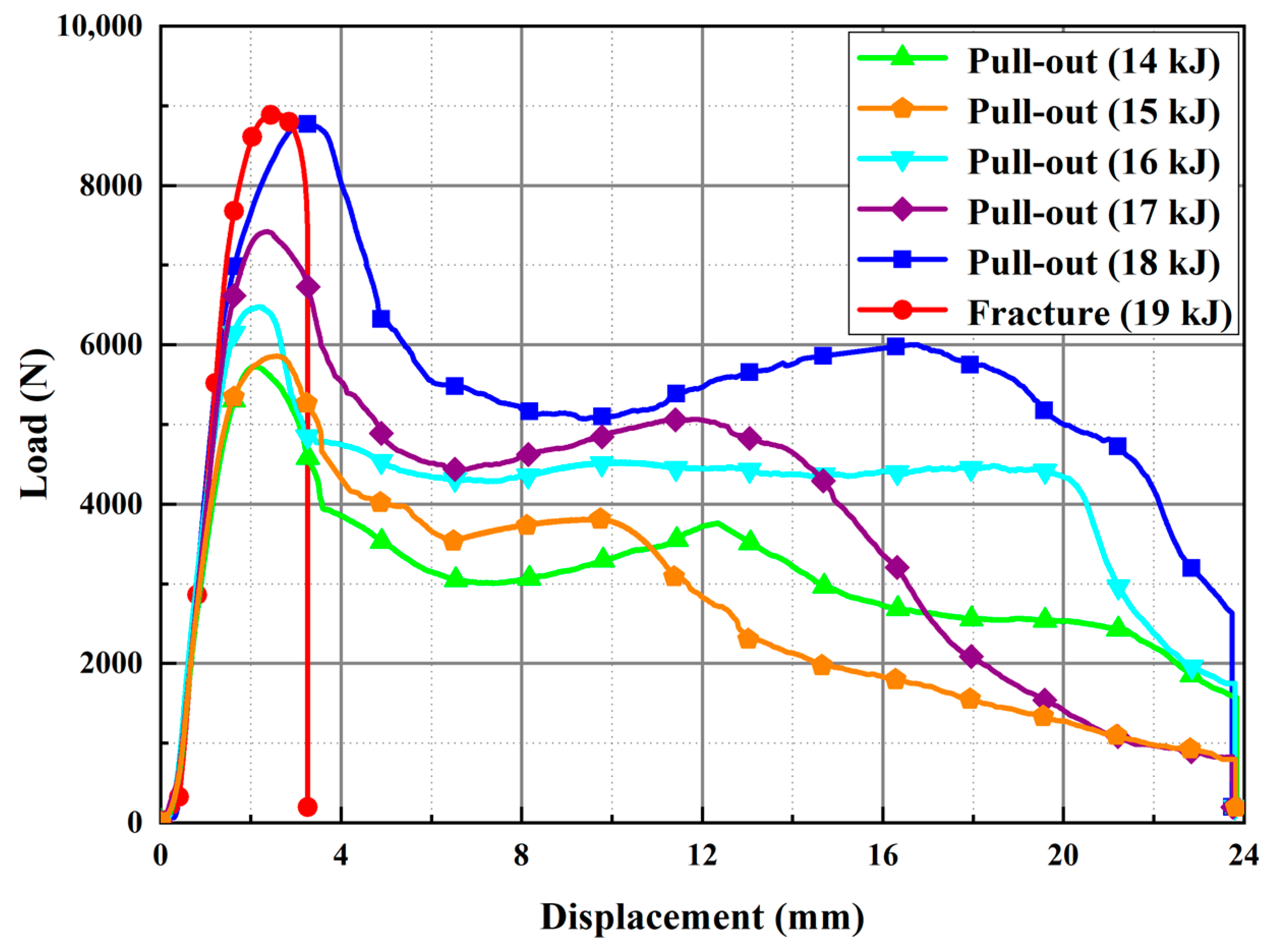
  • It was found by tensile tests and morphology observation that the maximum tensile load of the joint increased with the discharge energy. There were two failure modes of the joint. When the discharge energy was below 19 kJ, the failure mode of the joints was pull-out. When the discharge energy reached 19 kJ, the failure mode of the joints was a fracture.
  • When the failure mode of the joint transited from pull-out (18 kJ) to fracture (19 kJ), the maximum tensile load just increased from 8771.70 N to 8894.77 N, while the inner tube fractured brittlely, which was not suitable for service. Hence, the comprehensive performance of the joints was better when the discharge energy was 18 kJ.

Author Contributions

Writing—original draft, C.C.; methodology, C.C. and J.C.; data curation, C.C.; software, Y.Z.; investigation, Y.Z., J.C. and G.L.; conceptualization, D.W.; writing—review and editing, H.J.; funding acquisition, H.J. All authors have read and agreed to the published version of the manuscript.

Funding

This research was funded by the National Natural Science Foundation of China, grant numbers 51975202 and 52175315, the Natural Science Foundation of Hunan Province, grant numbers 2021JJ40073 and 2023JJ50340, and the Shenzhen Science and Technology Program, grant number KQTD20200820113110016.

Institutional Review Board Statement

This study was not conducted on humans or animals.

Informed Consent Statement

Not applicable.

Data Availability Statement

The raw/processed data required to reproduce these findings cannot be shared at this time due to technical or time limitations.

Conflicts of Interest

The authors declare no conflict of interest.

References

  1. Cui, J.J.; Sun, T.; Geng, H.H.; Yuan, W.; Li, G.Y.; Zhang, X. Effect of surface treatment on the mechanical properties and microstructures of Al-Fe single-lap joint by magnetic pulse welding. Int. J. Adv. Manuf. Technol. 2018, 98, 1081–1092. [Google Scholar] [CrossRef]
  2. Marmiroli, B.; Venditti, M.; Dotelli, G.; Spessa, E. The transport of goods in the urban environment: A comparative life cycle assessment of electric, compressed natural gas and diesel light-duty vehicles. Appl. Energy 2020, 260, 114236. [Google Scholar] [CrossRef]
  3. Jiang, H.; Liao, Y.X.; Jing, L.J.; Gao, S.; Li, G.Y.; Cui, J.J. Mechanical properties and corrosion behavior of galvanized steel/Al dissimilar joints. Arch. Civ. Mech. Eng. 2021, 21, 168. [Google Scholar] [CrossRef]
  4. Liao, Y.X.; Sun, H.; Wu, G.; Jin, C.; Cui, J.; Li, G.; Jiang, H. Effect of rivet arrangement on fatigue performance of electromagnetic riveted joint with Φ10 mm diameter rivet. Int. J. Fatigue 2023, 176, 107892. [Google Scholar] [CrossRef]
  5. Kayode, O.; Akinlabi, E.T. An overview on joining of aluminium and magnesium alloys using friction stir welding (FSW) for automotive lightweight applications. Mater. Res. Express 2020, 6, 112005. [Google Scholar] [CrossRef]
  6. Taub, A.; De Moor, E.; Luo, A.; Matlock, D.K.; Speer, J.G.; Vaidya, U. Materials for automotive lightweighting. Annu. Rev. Mater. Res. 2019, 49, 327–359. [Google Scholar] [CrossRef]
  7. Geng, H.H.; Xia, Z.H.; Zhang, X.; Li, G.Y.; Cui, J.J. Microstructures and mechanical properties of the welded AA5182/HC340LA joint by magnetic pulse welding. Mater. Charact. 2018, 138, 229–237. [Google Scholar] [CrossRef]
  8. Zhu, C.C.; Sun, L.Q.; Gao, W.L.; Li, G.Y.; Cui, J.J. The effect of temperature on microstructure and mechanical properties of Al/Mg lap joints manufactured by magnetic pulse welding. J. Mater. Res. Technol. 2019, 8, 3270–3280. [Google Scholar] [CrossRef]
  9. Weber, F.; Gebhard, J.; Gitschel, R.; Goyal, S.; Kamaliev, M.; Wernicke, S.; Tekkaya, A.E. Joining by forming—A selective review. J. Adv. Join. Process. 2021, 3, 100054. [Google Scholar] [CrossRef]
  10. Mori, K.; Bay, N.; Fratini, L.; Micari, F.; Tekkaya, A.E. Joining by plastic deformation. CIRP Ann.-Manuf. Technol. 2013, 62, 673–694. [Google Scholar] [CrossRef]
  11. Groche, P.; Wohletz, S.; Brenneis, M.; Pabst, C.; Resch, F. Joining by forming-A review on joint mechanisms, applications and future trends. J. Mater. Process. Technol. 2014, 214, 1972–1994. [Google Scholar] [CrossRef]
  12. Abe, Y.; Saito, T.; Mori, K.; Kato, T. Mechanical clinching with dies for control of metal flow of ultra-high-strength steel and high-strength steel sheets. Proc. Inst. Mech. Eng. Part B J. Eng. Manuf. 2018, 232, 644–649. [Google Scholar] [CrossRef]
  13. Pragana, J.P.M.; Silva, C.M.A.; Braganca, I.M.F.; Alves, L.M.; Martins, P.A.F. A new joining by forming process to produce lap joints in metal sheets. CIRP Ann.-Manuf. Technol. 2018, 67, 301–304. [Google Scholar] [CrossRef]
  14. Zhang, Q.; Zhang, Y.S.; Cao, M.; Ben, N.Y.; Ma, X.W.; Ma, H.X. Joining process for copper and aluminum tubes by rotary swaging method. Int. J. Adv. Manuf. Technol. 2017, 89, 163–173. [Google Scholar] [CrossRef]
  15. Marre, M.; Rautenberg, J.; Tekkaya, A.E.; Zabel, A.; Biermann, D.; Wojciechowski, J.; Przybylski, W. An experimental study on the groove design for joints produced by hydraulic expansion considering axial or torque load. Mater. Manuf. Process. 2012, 27, 545–555. [Google Scholar] [CrossRef]
  16. Ossenkemper, S.; Dahnke, C.; Tekkaya, A.E. Analytical and experimental bond strength investigation of cold forged composite shafts. J. Mater. Process. Technol. 2019, 264, 190–199. [Google Scholar] [CrossRef]
  17. Cai, D.; An, H.; Li, G.Y.; Ou, H.; Cui, J.J.; Jiang, H. Local flanging process on a curved wind deflector using electromagnetic forming. J. Manuf. Process. 2022, 84, 1030–1041. [Google Scholar] [CrossRef]
  18. Satonkar, N.; Gopalan, V. Simulation of electromagnetic forming process and optimization of geometric parameters of perforated Al sheet using RSM. Mathematics 2023, 11, 1983. [Google Scholar] [CrossRef]
  19. Psyk, V.; Risch, D.; Kinsey, B.L.; Tekkaya, A.E.; Kleiner, M. Electromagnetic forming-A review. J. Mater. Process. Technol. 2011, 211, 787–829. [Google Scholar] [CrossRef]
  20. Park, Y.B.; Kim, H.Y.; Oh, S.I. Design of axial/torque joint made by electromagnetic forming. Thin Wall Struct. 2005, 43, 826–844. [Google Scholar] [CrossRef]
  21. Areda, G.T.; Kore, S.D. Numerical study and experimental investigation on electromagnetic crimping for tube-to-rod configuration. Int. J. Precis. Eng. Manuf. 2019, 20, 181–191. [Google Scholar] [CrossRef]
  22. Kumar, R.; Kore, S.D. Electromagnetic crimping in tube-to-cylinder configuration: Influence of the base profiles on the joint quality. J. Test. Eval. 2018, 46, 1064–1075. [Google Scholar] [CrossRef]
  23. Rajak, A.K.; Kore, S.D. Experimental investigation of aluminium-copper wire crimping with electromagnetic process: Its advantages over conventional process. J. Manuf. Process. 2017, 26, 57–66. [Google Scholar] [CrossRef]
  24. Weddeling, C.; Woodward, S.T.; Marre, M.; Nellesen, J.; Psyk, V.; Tekkaya, A.E.; Tillmann, W. Influence of groove characteristics on strength of form-fit joints. J. Mater. Process. Technol. 2011, 211, 925–935. [Google Scholar] [CrossRef]
  25. Chen, C.; Han, Z.C.; Cui, J.J.; Li, G.Y.; Jiang, H. Study on magnetic pulse crimping process for joining large-diameter aluminum alloy tube/magnesium alloy shaft. Int. J. Adv. Manuf. Technol. 2023, 127, 527–546. [Google Scholar] [CrossRef]
  26. Jimbert, P.; Eguia, I.; Gutierrez, M.A.; Gonzalez, B.; Daehn, G.S.; Zhang, Y.; Anderson, R.; Sundberg, H.; Olsson, S.O.; Brännström., P. Flanging and hemming of auto body panels using the electro magnetic forming technology. In Proceedings of the 3rd International Conference on High Speed Forming (ICHSF), Dortmund, Germany, 11–12 March 2008. [Google Scholar] [CrossRef]
  27. Chu, Y.Y.; Lee, R.S. Effects of blank design on the electromagnetic flanging process. Proc. Inst. Mech. Eng. Part B J. Eng. Manuf. 2010, 224, 75–86. [Google Scholar] [CrossRef]
  28. Deng, H.K.; Mao, Y.F.; Li, G.Y.; Zhang, X.; Cui, J.J. AA5052 failure prediction of electromagnetic flanging process using a combined fracture model. Arch. Civ. Mech. Eng. 2022, 22, 84. [Google Scholar] [CrossRef]
  29. GB/T 228.1-2021; Metallic Materials-Tensile Testing-Part 1: Method of Test at Room Temperature. National Standards of the People’s Republic of China: Beijing, China, 2021.
  30. Liu, Q.X.X.; Wang, S.L.; Li, G.Y.; Cui, J.J.; Yu, Y.; Jiang, H. A sandwich structure realizing the connection of CFRP and Al sheets using magnetic pulse welding. Compos. Struct. 2022, 295, 115865. [Google Scholar] [CrossRef]
  31. Jiang, H.; Hong, Z.B.; Li, G.Y.; Cui, J.J. Numerical and experiment investigation on joining process and failure behaviors of CFRP/Al electromagnetic riveted joint. Mech. Adv. Mater. Struct. 2022, 29, 1996–2007. [Google Scholar] [CrossRef]
  32. Johnson, G.R.; Cook, W.H. Fracture characteristics of three metals subjected to various strains, strain rates, temperatures and pressures. Eng. Fract. Mech. 1985, 21, 31–48. [Google Scholar] [CrossRef]
  33. Nam, H.S.; Je, J.H.; Han, J.J.; Kim, Y.J. Investigation of crack tip stress and strain fields at crack initiation of A106 Gr. B carbon steels under high strain rates. In Proceedings of the 20th European Conference on Fracture (ECF), Trondheim, Norway, 30 June–4 July 2014. [Google Scholar] [CrossRef]
  34. Liu, Q.X.X.; Yao, Y.H.; Xia, Z.H.; Li, G.Y.; Cui, J.J.; Jiang, H. A novel method for joining steel/al tube parts based on electromagnetic force by flat coil. Coatings 2021, 11, 1356. [Google Scholar] [CrossRef]
  35. Wu, Y.Z.; Ma, Y.Q.; Gao, H.T.; Zhang, Y.; Liu, S.Y. Electrical conductibility of copper clad steel wire by drawing at room temperature. Key Eng. Mater. 2007, 334–335, 321–324. [Google Scholar] [CrossRef]
  36. Yao, Y.H.; Jing, L.J.; Wang, S.L.; Li, G.Y.; Cui, J.J.; Tang, X.H.; Jiang, H. Mechanical properties and joining mechanisms of Al-Fe magnetic pulse welding by spot form for automotive application. J. Manuf. Process. 2022, 76, 504–517. [Google Scholar] [CrossRef]
  37. Liu, Z.D.; Wang, G.; Feng, Y.C.; Li, L.X. High-strain-rate constitutive parameters of 6061 aluminum alloys. Min. Metall. Eng. 2011, 31, 120–123. [Google Scholar] [CrossRef]
  38. Nassiraei, H.; Mojtahedi, A.; Lotfollahi-Yaghin, M.A. Static strength of X-joints reinforced with collar plates subjected to brace tensile loading. Ocean Eng. 2018, 161, 227–241. [Google Scholar] [CrossRef]
Figure 1. Schematic of the structural assembly.
Metals 13 01529 g001
Figure 2. The EMS and the tool: (a) EMS; (b) tool.
Metals 13 01529 g002
Figure 3. Schematic of the joining process for the joint.
Metals 13 01529 g003
Figure 4. The tensile test.
Metals 13 01529 g004
Figure 5. Assembly structure of the numerical model.
Metals 13 01529 g005
Figure 6. The Rogowski coil and time–current curve.
Metals 13 01529 g006
Figure 7. Comparison of the experiment and simulation: (a) Cross-section; (b) longitudinal section; (c) comparison of each measured parameter.
Metals 13 01529 g007
Figure 8. Distribution of current density on the outer tube.
Metals 13 01529 g008
Figure 9. Distribution of Lorentz force on the outer tube.
Metals 13 01529 g009
Figure 10. Deformation of the tubes.
Metals 13 01529 g010
Figure 11. Failure mode of the joint: (a) Failure mode of pull-out; (b) failure mode of fracture.
Metals 13 01529 g011
Figure 12. Typical displacement–load curves of two failure modes.
Metals 13 01529 g012
Figure 13. Schematic of process for the failure mode of pull-out.
Metals 13 01529 g013
Figure 14. Macro-morphology of the joint: (a) Cross-section at the discharge energy of 18 kJ; (b) cross-section at the discharge energy of 19 kJ; (c) longitudinal section at the discharge energy of 18 kJ; (d) longitudinal section at the discharge energy of 19 kJ.
Metals 13 01529 g014aMetals 13 01529 g014b
Figure 15. Metallographic structure of the outer tube.
Metals 13 01529 g015
Figure 16. Fracture micro-morphology of the inner tube.
Metals 13 01529 g016
Table 1. Chemical compositions of materials (in wt.%).
MaterialSiCrCuMnCZnVPTiMoMgCoAlFe
T6061-T60.4~0.80.04~0.350.15~0.4<0.15-<0.25-0.04~0.35<0.15-0.5~1.2-Bal.<0.7
Q195<0.05<0.3-0.3~0.50.12~0.2-<0.03<0.05<0.03<0.03-<0.03 Bal.
Table 2. Mechanical properties of materials.
MaterialYoung’s Modulus (GPa)Yield Strength (MPa)Tensile Strength (MPa)Density (kg/m3)Poisson Ratio
T6061-T66924029027000.330
Q19521219539076900.286
Table 3. Number of units and nodes in each part in the numerical model.
PartNumber of ElementsNumber of Nodes
Coil21,22428,050
Field shaper36724654
Outer tube40,19660,534
Inner tube35597296
Table 4. The J-C model parameters of materials.
MaterialA (MPa)B (MPa)nC
T6061-T6205.78130.590.3570.015
Q195294818.720.3792−0.06441
Table 5. The material parameters of each part.
PartMaterialDensity (kg/m3)Young’s Modulus (GPa)Poisson RatioMaterial ModelElectrical Conductivity (S/m)
Coil6061T62700690.330Rigid2.46 × 107
Field shaperCopper8900970.330Rigid5.71 × 107
Outer tube6061T62700690.330Plastic2.46 × 107
Inner tubeQ19576902120.286Plastic0.65 × 107
Table 6. Average maximum tensile load and failure mode of the joint at different discharge energies.
Discharge Energy (kJ)Average Maximum Tensile Load (N)Failure Mode
145726.90Pull-out
155861.79Pull-out
166475.27Pull-out
177422.24Pull-out
188771.70Pull-out
198894.77Fracture
Disclaimer/Publisher’s Note: The statements, opinions and data contained in all publications are solely those of the individual author(s) and contributor(s) and not of MDPI and/or the editor(s). MDPI and/or the editor(s) disclaim responsibility for any injury to people or property resulting from any ideas, methods, instructions or products referred to in the content.

