Active and Passive Thermal Management in Wire Arc Additive Manufacturing
Abstract
1. Introduction
2. Materials and Methods
2.1. Component Fabrication
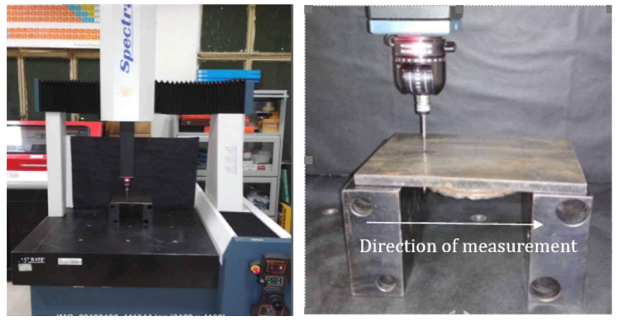
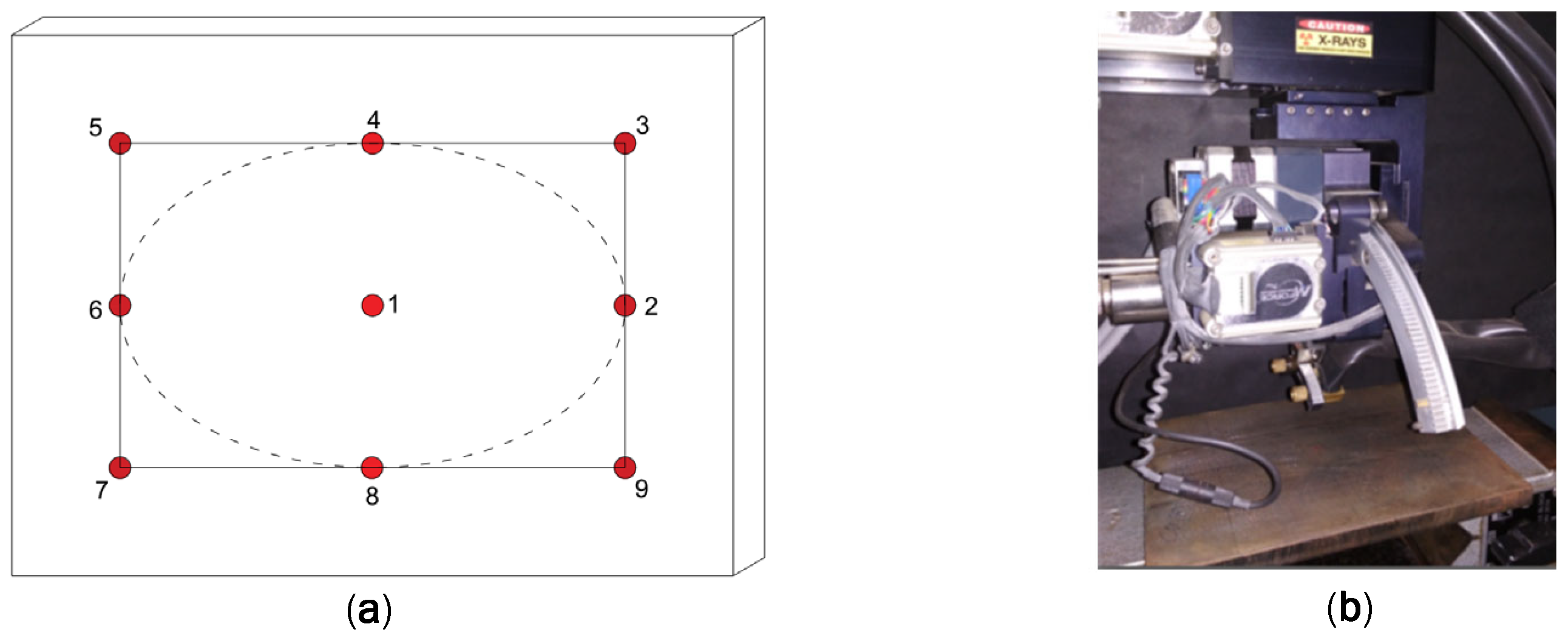
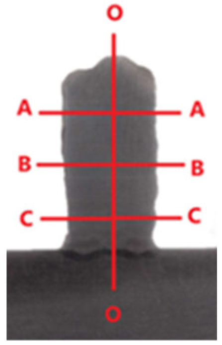
2.2. Measurement Methodology
3. Passive and Active Approaches to Thermal Management
3.1. Passive Approach
- Process parameters of deposition (welding current and traverse speed)
- Shape/geometry of the component being deposited
- Pace of the build process (with or without interlayer pause or delay)
- External intervention on the build system, if any
3.2. Active Approach
4. Results and Discussions
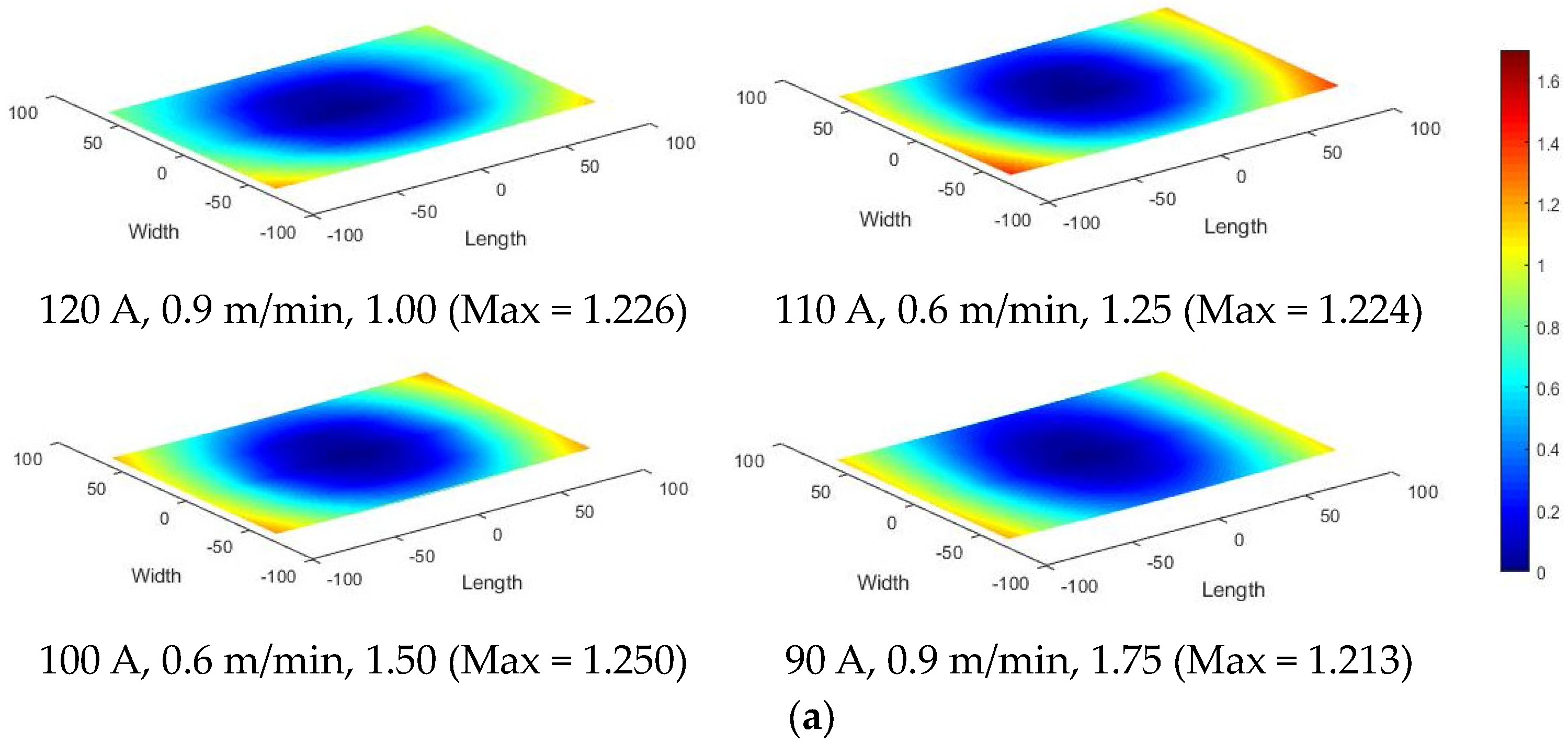
4.1. Distortion with Passive and Active Thermal Management
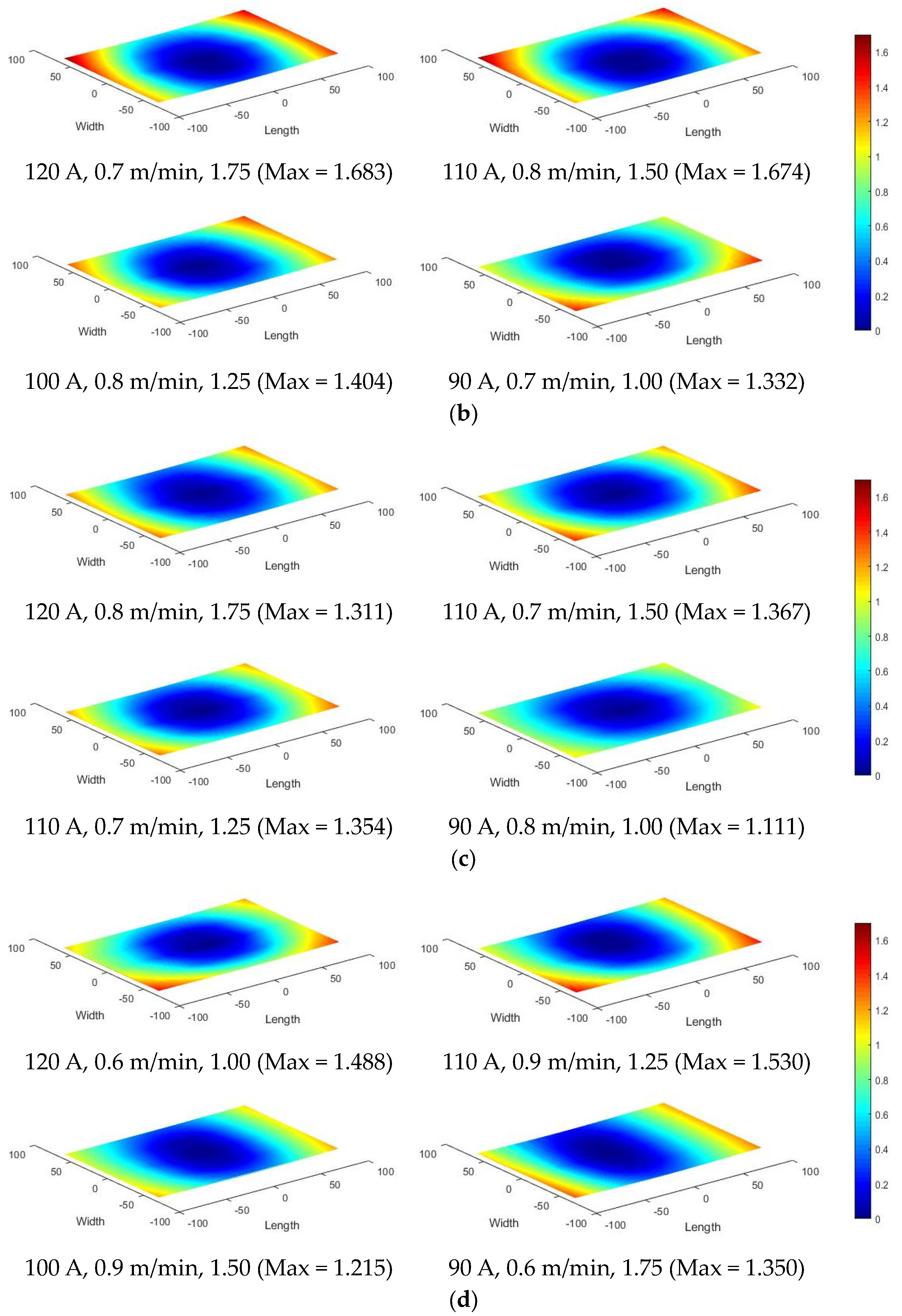
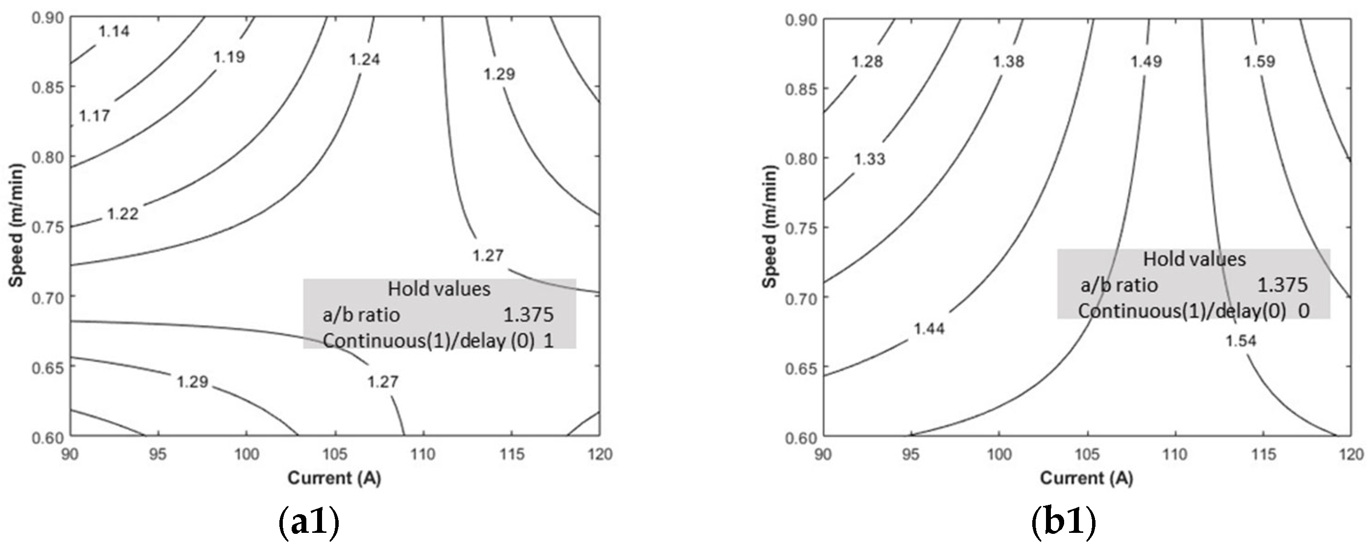
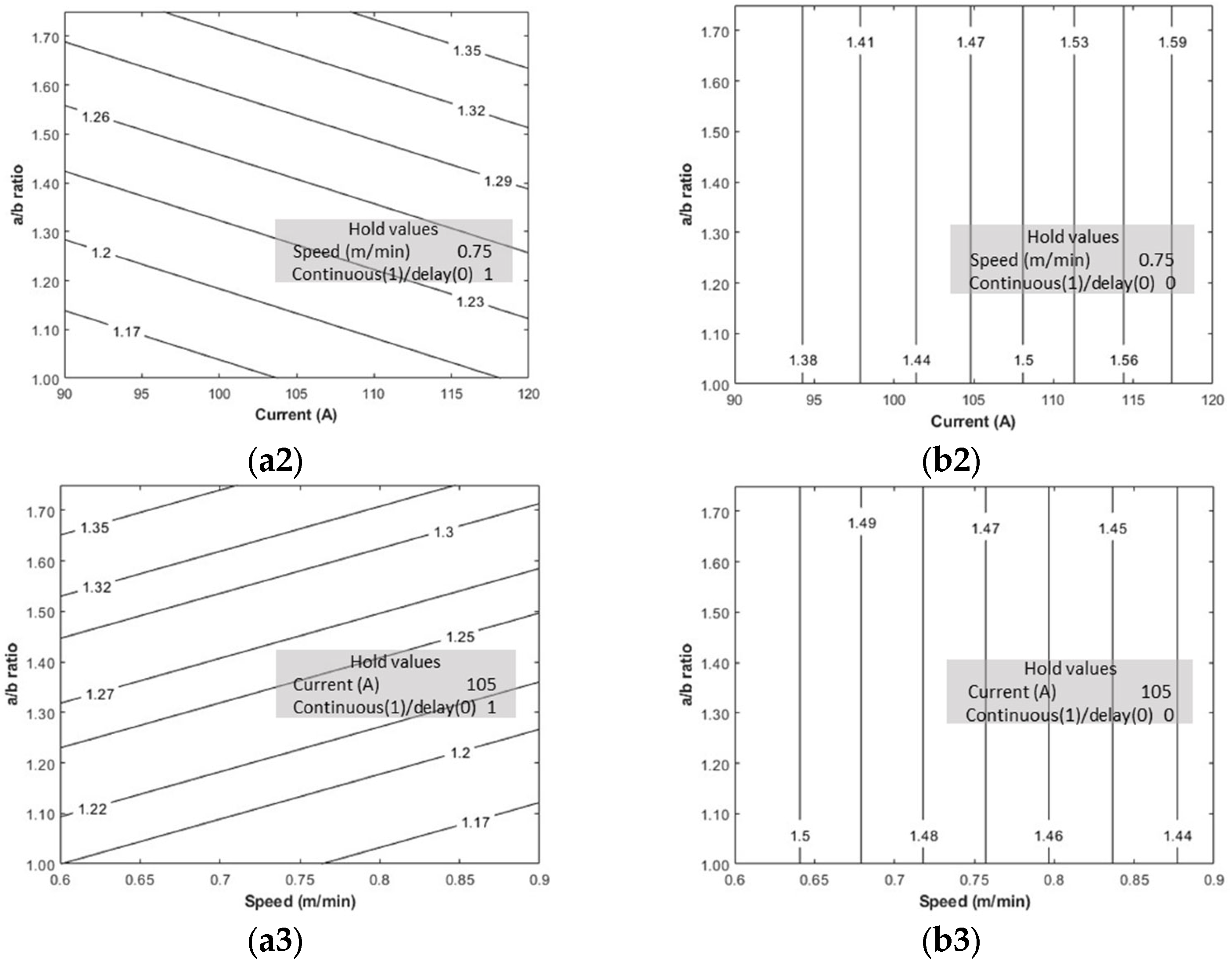
- Distortion is lower for continuous deposition than with an interlayer delay. This is possibly due to the progressive nature of the thermal evolution (in continuous deposition) against the intermittent kind (in delayed deposit).
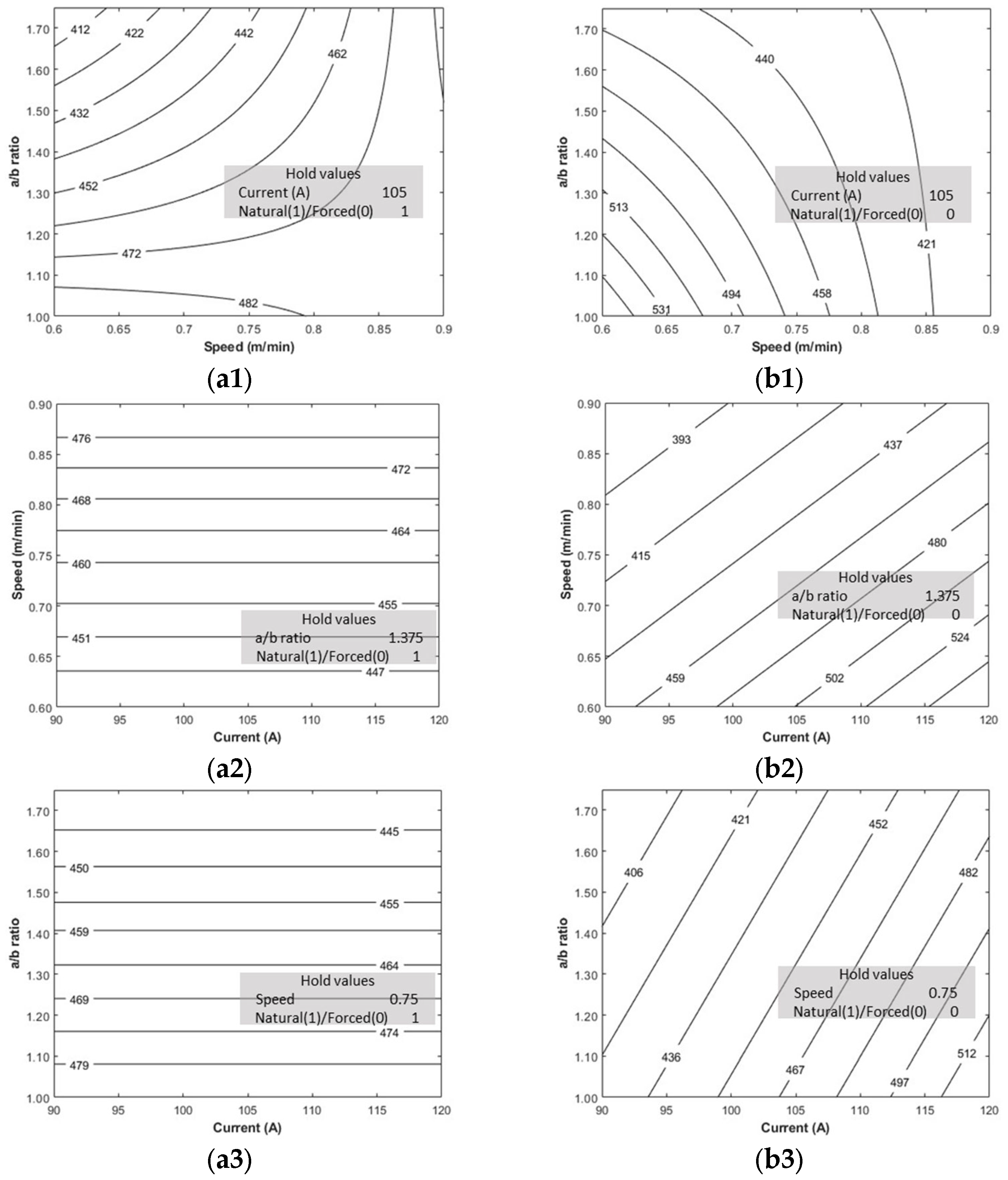
- Low current and/or high torch speed help decrease the thermal peaks and distortions.
- With the continual accumulation of heat, the aspect ratio was found to have no significant effect in the case of continuous deposition. However, it was observed to be influencing the distortions in the case of delayed deposit.
4.2. Residual Stresses with Passive and Active Thermal Management
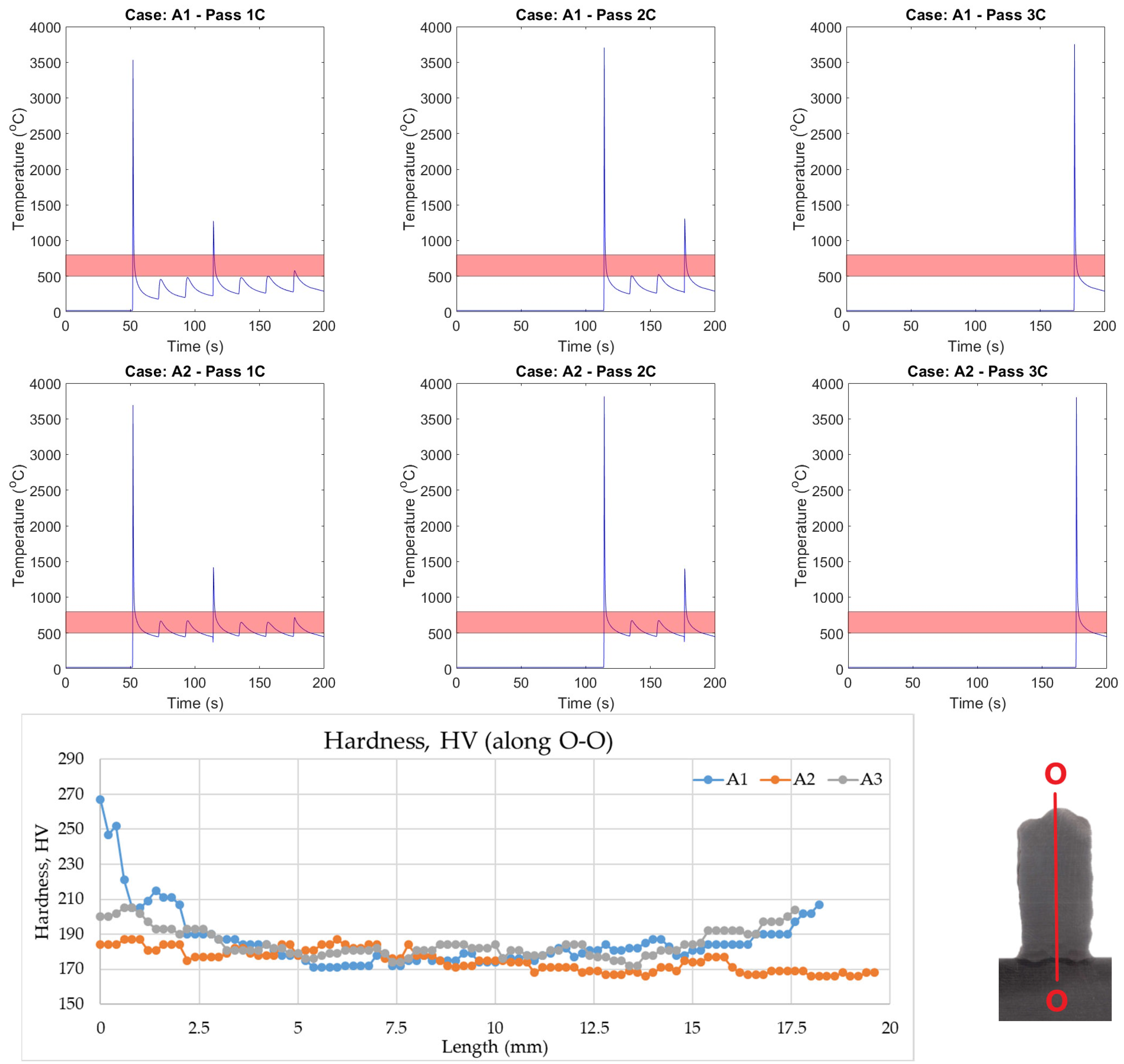
4.3. Hardness Variation with Passive and Active Thermal Management
4.4. Intralayer and Interlayer Thermal Evolution
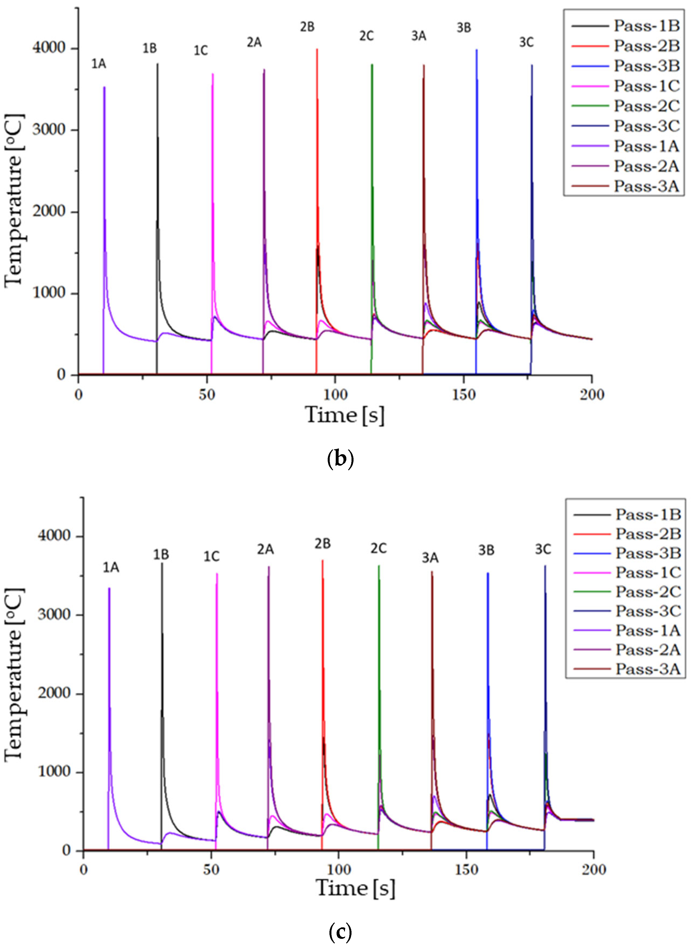
- Insulated substrate (Natural cooling, continuous, 120 A, 0.9 m/min, 1.0)
- Insulated + heated substrate (Natural cooling, heated substrate (400 °C), continuous, 120 A, 0.9 m/min, 1.0)
4.5. Comparison of Hardness Based on T8/5
5. Conclusions
- Thermal management is an effective tool that can alter the distortion and residual stress pattern and the mechanical properties in an AM component. Measures to regulate the cooling and heating rate in the AM component can be designed to have predictive capabilities.
- The qualitative effects of process conditions on the distortion and residual stresses are evaluated using analysis of variance (ANOVA) for the passive thermal management approach.
- Current and torch speed are the parameters that affect distortion. Increasing current or decreasing speed increases the heat input rate, leading to higher distortion. In the case of continuous deposition for a given torch speed, a higher current can cause increased distortion due to greater heat input. Additionally, an increased aspect ratio can lead to uneven heat concentration, resulting in greater distortion. However, delayed deposition minimizes the impact of the aspect ratio on distortion, as it allows more time for heat to spread.
- Torch speed and geometry affect the residual stresses; the rate of heat distribution and geometry change causes the stress to accumulate, which increases the residual stresses. The welding current influences the residual stresses in the case of forced cooling, whereas the effect is insignificant in the natural cooling for the range of experiments considered.
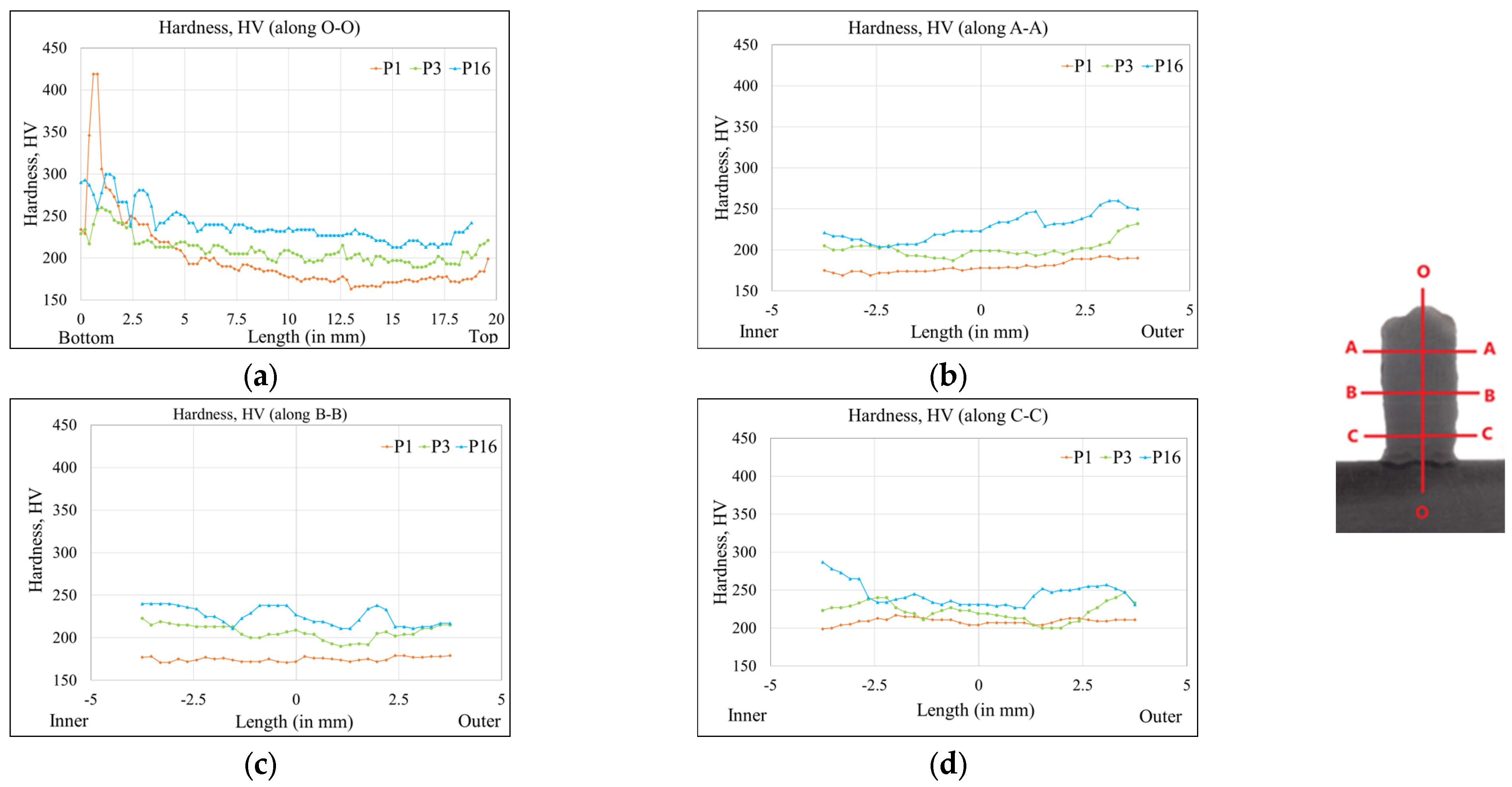
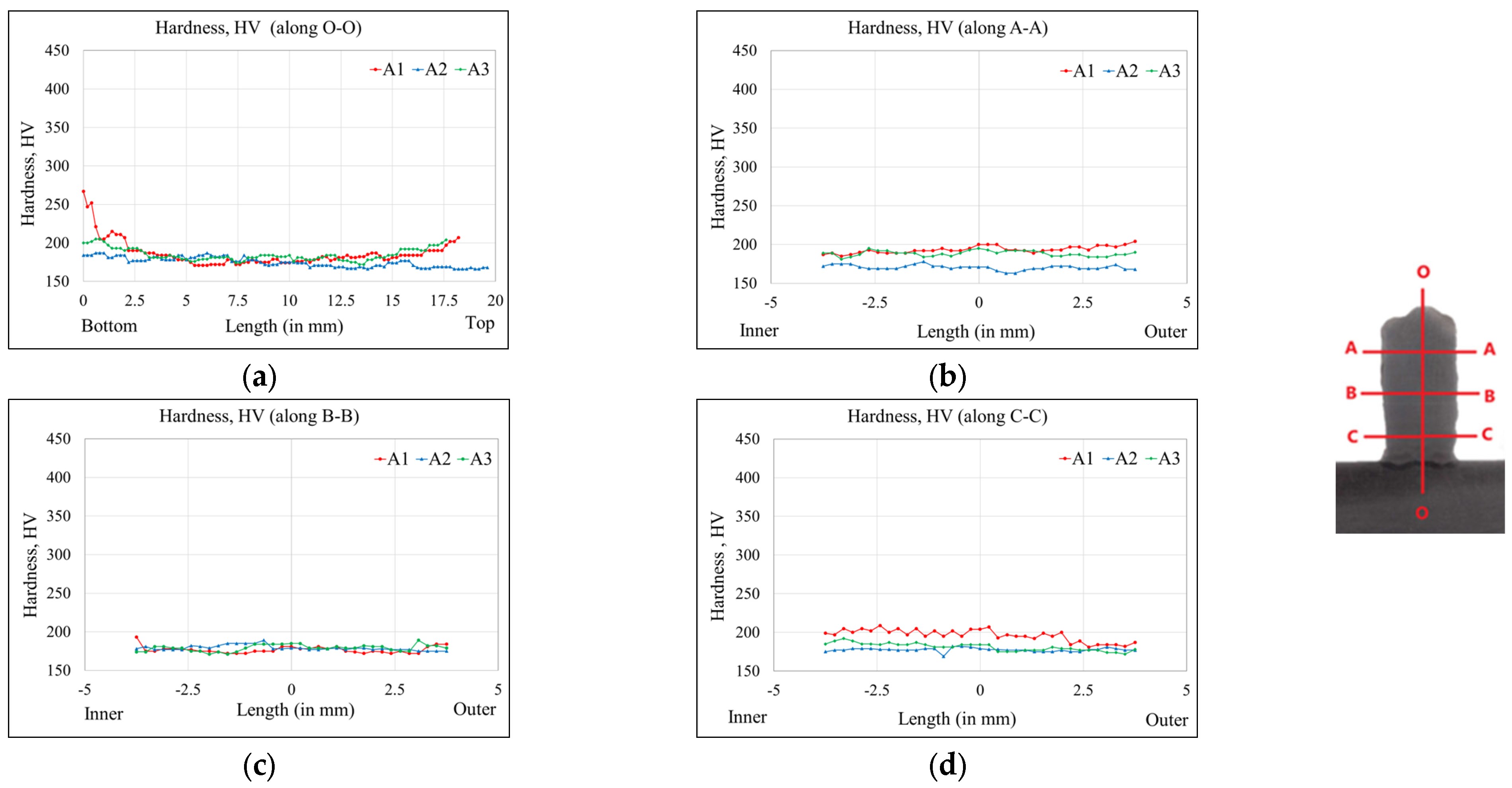
- Heating the substrate shows a lower distortion comparatively and a uniform hardness across the cross-section.
- Heating the substrate is an effective measure to manage the in-process distortion. The components that are difficult to complete because of in-process distortion are expected to manufacture with thermal management.
- Thermal management techniques do depend on geometry. The efficacy of the technique needs to be evaluated through simulation and limited experiments before implementation. The maximum distortion and maximum stress can be expressed as a function of process parameters for a given thermal management technique for a given geometry.
- The AM component may have through-wall thickness variation in the properties (in addition to the across-layer variation). A concave surface may benefit self-heating, thereby reducing the cooling rate.
- Dynamic management of process parameters with layers has been found to have a limited effect in the current investigation, perhaps because of the fewer number of deposited layers. However, this approach must be checked with a component with many layers.
- The thermal management results of this investigation can be deployed to other AM processes. The coupling of active and passive management merits investigation to further the benefits of thermal management.
Author Contributions
Funding
Data Availability Statement
Acknowledgments
Conflicts of Interest
References
- Farzaneh, A.; Khorasani, M.; Farabi, E.; Gibson, I.; Leary, M.; Ghasemi, A.; Rolfe, B. Sandwich structure printing of Ti-Ni-Ti by directed energy deposition. Virtual Phys. Prototyp. 2022, 17, 1006–1030. [Google Scholar] [CrossRef]
- Chen, X.; Fu, Y.; Kong, F.; Li, R.; Xiao, Y.; Hu, J.; Zhang, H. An in-process multi-feature data fusion nondestructive testing approach for wire arc additive manufacturing. Rapid Prototyp. J. 2022, 28, 573–584. [Google Scholar] [CrossRef]
- Chi, Y.; Murali, N.; Liu, J.; Liese, M.; Li, X. Wire arc additive manufacturing (WAAM) of nanotreated aluminum alloy 6061. Rapid Prototyp. J. 2022. ahead of print. [Google Scholar] [CrossRef]
- Mishra, A.; Paul, A.R.; Mukherjee, M.; Singh, R.K.; Sharma, A.K. Evaluation of Cu-Ti dissimilar interface characteristics for wire arc additive manufacturing process. Rapid Prototyp. J. 2023, 29, 366–377. [Google Scholar] [CrossRef]
- Somashekara, M.A.; Naveenkumar, M.; Kumar, A.; Viswanath, C.; Simhambhatla, S. Investigations into effect of weld-deposition pattern on residual stress evolution for metallic additive manufacturing. Int. J. Adv. Manuf. Technol. 2017, 90, 2009–2025. [Google Scholar] [CrossRef]
- Zhao, H.; Zhang, G.; Yin, Z.; Wu, L. Effects of Interpass Idle Time on Thermal Stresses in Multipass Multilayer Weld-Based Rapid Prototyping. J. Manuf. Sci. Eng. 2013, 135, 011016. [Google Scholar] [CrossRef]
- Denlinger, E.R.; Heigel, J.C.; Michaleris, P.; Palmer, T.A. Effect of inter-layer dwell time on distortion and residual stress in additive manufacturing of titanium and nickel alloys. J. Mater. Process. Technol. 2015, 215, 123–131. [Google Scholar] [CrossRef]
- Zhao, X.; Iyer, A.; Promoppatum, P.; Yao, S.C. Numerical modeling of the thermal behavior and residual stress in the direct metal laser sintering process of titanium alloy products. Addit. Manuf. 2017, 14, 126–136. [Google Scholar] [CrossRef]
- Hoye, N.; Li, H.J.; Cuiuri, D.; Paradowska, A.M. Measurement of Residual Stresses in Titanium Aerospace Components Formed via Additive Manufacturing. Mater. Sci. Forum 2014, 777, 124–129. [Google Scholar] [CrossRef]
- Klingbeil, N.W.; Beuth, J.L.; Chin, R.K.; Amon, C.H. Residual stress-induced warping in direct metal solid freeform fabrication. Int. J. Mech. Sci. 2002, 44, 57–77. [Google Scholar] [CrossRef]
- Klingbeil, N.W.; Zinn, J.W.; Beuth, J.L. Measurement of Residual Stresses in Parts Created by Shape Deposition Manufacturing. In Proceedings of the International Solid Freeform Fabrication Symposium, Austin, TX, USA, 11–13 August 1997; p. 8. [Google Scholar]
- Colegrove, P.A.; Coules, H.E.; Fairman, J.; Martina, F.; Kashoob, T.; Mamash, H.; Cozzolino, L.D. Microstructure and residual stress improvement in wire and arc additively manufactured parts through high-pressure rolling. J. Mater. Process. Technol. 2013, 213, 1782–1791. [Google Scholar] [CrossRef]
- Vastola, G.; Zhang, G.; Pei, Q.X.; Zhang, Y.W. Controlling of residual stress in additive manufacturing of Ti6Al4V by finite element modeling. Addit. Manuf. 2016, 12, 231–239. [Google Scholar] [CrossRef]
- Lockett, H.; Ding, J.; Williams, S.; Martina, F. Design for Wire + Arc Additive Manufacture: Design rules and build orientation selection. J. Eng. Des. 2017, 28, 568–598. [Google Scholar] [CrossRef]
- Huang, W.; Wang, Q.; Ma, N.; Kitano, H. Distribution characteristics of residual stresses in typical wall and pipe components built by wire arc additive manufacturing. J. Manuf. Process. 2022, 82, 434–447. [Google Scholar] [CrossRef]
- Cambon, C.; Bendaoud, I.; Rouquette, S.; Soulié, F. A WAAM benchmark: From process parameters to thermal effects on weld pool shape, microstructure and residual stresses. Mater. Today Commun. 2022, 33, 104235. [Google Scholar] [CrossRef]
- Scharf-Wildenhain, R.; Haelsig, A.; Hensel, J.; Wandtke, K.; Schroepfer, D.; Kromm, A.; Kannengiesser, T. Influence of Heat Control on Properties and Residual Stresses of Additive-Welded High-Strength Steel Components. Metals 2022, 12, 951. [Google Scholar] [CrossRef]
- Doumenc, G.; Couturier, L.; Courant, B.; Paillard, P.; Benoit, A.; Gautron, E.; Girault, B.; Pirling, T.; Cabeza, S.; Gloaguen, D. Investigation of microstructure, hardness and residual stresses of wire and arc additive manufactured 6061 aluminium alloy. Materialia 2022, 25, 101520. [Google Scholar] [CrossRef]
- Fan, D.; Gao, M.; Li, C.; Huang, J.; Yu, X. Residual stress and microstructure properties by trailing cooling of argon gas of wire and arc additive manufacturing. J. Manuf. Process. 2022, 77, 32–39. [Google Scholar] [CrossRef]
- Reddy, S.; Kumar, M.; Panchagnula, J.S.; Parchuri, P.K.; Kumar, S.S.; Ito, K.; Sharma, A. A new approach for attaining uniform properties in build direction in additive manufactured components through coupled thermal-hardness model. J. Manuf. Process. 2019, 40, 46–58. [Google Scholar] [CrossRef]
- Montevecchi, F.; Venturini, G.; Grossi, N.; Scippa, A.; Campatelli, G. Heat accumulation prevention in Wire-Arc-Additive-Manufacturing using air jet impingement. Manuf. Lett. 2018, 17, 14–18. [Google Scholar] [CrossRef]
- Lu, X.; Chiumenti, M.; Cervera, M.; Zhang, G.; Lin, X. Mitigation of residual stresses and microstructure homogenization in directed energy deposition processes. Eng. Comput. 2022, 38, 4771–4790. [Google Scholar] [CrossRef]
- Sharma, S.D.; Saluja, R.; Moeed, K.M. A review on effect of preheating and/or post weld heat treatment (PWHT) on hardened steel. Int. J. Tech. Res. App. 2013, 1, 5–7. [Google Scholar]







| Attribute | Specifications |
|---|---|
| Feed wire material | AWS ER 70 S-6 (steel alloy AWS A5.18) |
| Diameter of the feed wire | 0.8 mm |
| Shielding gas | 80% Ar and 20% CO2 |
| Gas flow rate | 10−12 L/min |
| Weld plate dimensions | 200 mm × 150 mm × 11 mm |
| Coolant plate dimensions | 200 mm × 150 mm × 25 mm |
| Coolant duct diameter | 10 mm (five holes) |
| Attribute | Baseplate and Coolant Plate Properties | Filler Wire Properties |
|---|---|---|
| Ultimate tensile strength | 650–850 MPa | 480 MPa |
| Yield strength | 350–550 MPa | 400 MPa |
| Melting temperature | 1450–1510 °C | - |
| Variable | Generic Terms | Equivalent in WAAM | Selected Parameters |
|---|---|---|---|
| Process Parameters | Heat Intensity | Current | 90, 100, 110, 120 A |
| Material Deposition Rate | Torch Speed | 0.6, 0.7, 0.8, 0.9 m/min | |
| Control Measures | Temperature Control (External Cooling/Heating) | Natural Cooling/ Forced Cooling | Coolant through substrate: (yes/no) |
| Pace Control (Continuous/ Intermittent) | Continuous vs. Pause after every layer | Continuous vs. Pause after every layer | |
| Mass/heat Distribution | Geometry | Proximity/Distribution | Ellipse with a/b ratio: 1.00, 1.25, 1.5, 1.75 |
| Exp. No. | Natural Cooling/ Forced Cooling | Continuous/ Delay | Current (in A) | Speed (m/min) | a/b Ratio |
|---|---|---|---|---|---|
| P1 | Natural cooling | Continuous | 120 | 0.90 | 1.00 |
| P2 | Forced cooling | Delay | 110 | 0.90 | 1.25 |
| P3 | Natural cooling | Delay | 110 | 0.80 | 1.50 |
| P4 | Natural cooling | Delay | 120 | 0.70 | 1.75 |
| P5 | Forced cooling | Continuous | 120 | 0.80 | 1.75 |
| P6 | Forced cooling | Continuous | 90 | 0.80 | 1.00 |
| P7 | Forced cooling | Delay | 100 | 0.90 | 1.50 |
| P8 | Natural cooling | Delay | 100 | 0.80 | 1.25 |
| P9 | Forced cooling | Continuous | 100 | 0.70 | 1.25 |
| P10 | Natural cooling | Delay | 90 | 0.70 | 1.00 |
| P11 | Natural cooling | Continuous | 90 | 0.90 | 1.75 |
| P12 | Natural cooling | Continuous | 110 | 0.60 | 1.25 |
| P13 | Forced cooling | Delay | 120 | 0.60 | 1.00 |
| P14 | Natural cooling | Continuous | 100 | 0.60 | 1.50 |
| P15 | Forced cooling | Continuous | 110 | 0.70 | 1.50 |
| P16 | Forced cooling | Delay | 90 | 0.60 | 1.75 |
| Method of Cooling | Method of Deposition | Exp. No | Current (A) | Speed (m/min) | a/b Ratio | Max Stress (in MPa) | Min Stress (in MPa) | Distortion (in mm) |
|---|---|---|---|---|---|---|---|---|
| Passive approach | ||||||||
| N | C | P1 | 120 | 0.90 | 1.00 | 492.31 | 73.74 | 1.226 |
| N | C | P12 | 110 | 0.60 | 1.25 | 420.57 | 185.16 | 1.224 |
| N | C | P14 | 100 | 0.60 | 1.50 | 435.52 | 63.03 | 1.250 |
| N | C | P11 | 90 | 0.90 | 1.75 | 469.01 | 50.53 | 1.213 |
| N | D | P4 | 120 | 0.70 | 1.75 | 445.88 | −284.08 | 1.683 |
| N | D | P3 | 110 | 0.80 | 1.50 | 464.38 | 95.58 | 1.674 |
| N | D | P8 | 100 | 0.80 | 1.25 | 431.49 | −50.78 | 1.404 |
| N | D | P10 | 90 | 0.70 | 1.00 | 560.29 | 111.32 | 1.332 |
| F | C | P5 | 120 | 0.80 | 1.75 | 449.13 | −237.08 | 1.311 |
| F | C | P15 | 110 | 0.70 | 1.50 | 534.66 | 159.72 | 1.367 |
| F | C | P9 | 100 | 0.70 | 1.25 | 499.59 | −2.77 | 1.354 |
| F | C | P6 | 90 | 0.80 | 1.00 | 387.21 | 6.66 | 1.111 |
| F | D | P13 | 120 | 0.60 | 1.00 | 582.34 | 151.35 | 1.488 |
| F | D | P2 | 110 | 0.90 | 1.25 | 370.88 | 73.30 | 1.530 |
| F | D | P7 | 100 | 0.90 | 1.50 | 410.98 | −167.44 | 1.215 |
| F | D | P16 | 90 | 0.60 | 1.75 | 373.59 | −213.46 | 1.350 |
| Active approach | ||||||||
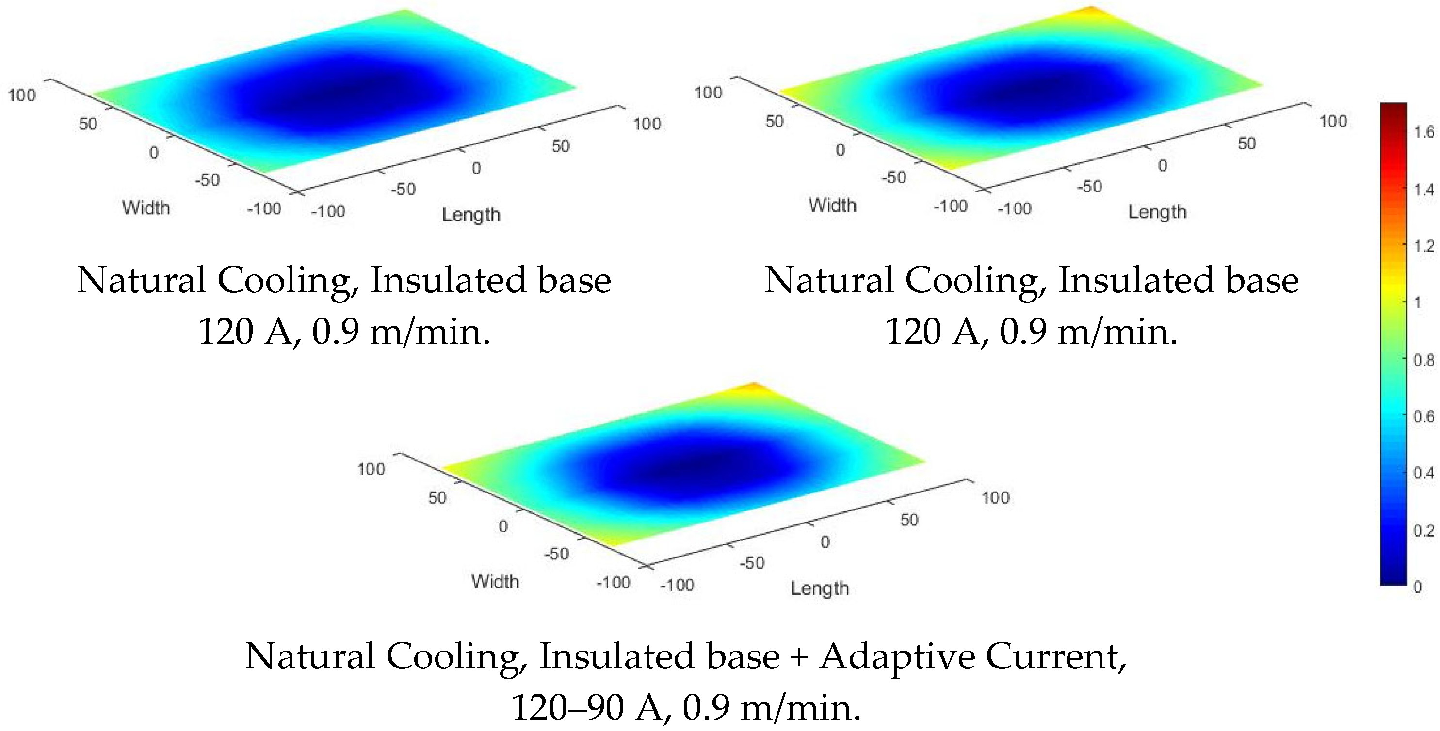
| N, IB | C | A1 | 120 | 0.90 | 1.00 | 367.74 | 63.04 | 0.529 |
| N, IHP | C | A2 | 120 | 0.90 | 1.00 | 350.68 | −21.43 | 0.431 |
| N, IB + A | C | A3 | 120–90 | 0.90 | 1.00 | 366.79 | −22.59 | 0.699 |
| Source | DF | Adj SS | Adj MS | F-Value | p-Value | |
|---|---|---|---|---|---|---|
| Regression | 5 | 11.8498 | 2.36996 | 2391.02 | 0.000 | |
| Current (A) | 1 | 0.2045 | 0.20450 | 206.32 | 0.000 | |
| Speed (m/min) | 1 | 0.1841 | 0.18409 | 185.72 | 0.000 | |
| Current (A) × Speed (m/min) | 1 | 0.1156 | 0.11563 | 116.66 | 0.000 | |
| Current (A) × Continuous(1)/delay(0) | 1 | 0.0107 | 0.01070 | 10.79 | 0.007 | |
| a/b ratio × Continuous(1)/delay(0) | 1 | 0.0043 | 0.00431 | 4.35 | 0.061 | |
| Error | 11 | 0.0109 | 0.00099 | |||
| Total | 16 | 11.8607 | ||||
| S | R-sq | R-sq (adj) | R-sq (pred) | |||
| 0.0314833 | 99.91% | 99.87% | 99.83% | |||
| Source | DF | Adj SS | Adj MS | F-Value | p-Value |
|---|---|---|---|---|---|
| Regression | 6 | 0.000080 | 0.000013 | 293.46 | 0.000 |
| Current (A) | 1 | 0.000000 | 0.000000 | 8.01 | 0.018 |
| Speed (m/min) | 1 | 0.000002 | 0.000002 | 33.96 | 0.000 |
| a/b ratio | 1 | 0.000001 | 0.000001 | 19.76 | 0.001 |
| Current (A) × Natural(1)/Forced(0) | 1 | 0.000000 | 0.000000 | 6.64 | 0.028 |
| Speed (m/min) × Natural(1)/Forced(0) | 1 | 0.000000 | 0.000000 | 7.69 | 0.020 |
| Speed (m/min) × a/b ratio | 1 | 0.000001 | 0.000001 | 12.39 | 0.006 |
| Error | 10 | 0.000000 | 0.000000 | - | - |
| Total | 16 | 0.000080 | - | - | - |
| Regression | 6 | 0.000080 | 0.000013 | 293.46 | 0.000 |
| S | R-sq | R-sq (adj) | R-sq (pred) | ||
| 0.0002129 | 99.44% | 99.10% | 98.54% | ||
Disclaimer/Publisher’s Note: The statements, opinions and data contained in all publications are solely those of the individual author(s) and contributor(s) and not of MDPI and/or the editor(s). MDPI and/or the editor(s) disclaim responsibility for any injury to people or property resulting from any ideas, methods, instructions or products referred to in the content. |
© 2023 by the authors. Licensee MDPI, Basel, Switzerland. This article is an open access article distributed under the terms and conditions of the Creative Commons Attribution (CC BY) license (https://creativecommons.org/licenses/by/4.0/).
Share and Cite
Nagallapati, V.; Khare, V.K.; Sharma, A.; Simhambhatla, S. Active and Passive Thermal Management in Wire Arc Additive Manufacturing. Metals 2023, 13, 682. https://doi.org/10.3390/met13040682
Nagallapati V, Khare VK, Sharma A, Simhambhatla S. Active and Passive Thermal Management in Wire Arc Additive Manufacturing. Metals. 2023; 13(4):682. https://doi.org/10.3390/met13040682
Chicago/Turabian StyleNagallapati, Vishwanath, Vivek Kumar Khare, Abhay Sharma, and Suryakumar Simhambhatla. 2023. "Active and Passive Thermal Management in Wire Arc Additive Manufacturing" Metals 13, no. 4: 682. https://doi.org/10.3390/met13040682
APA StyleNagallapati, V., Khare, V. K., Sharma, A., & Simhambhatla, S. (2023). Active and Passive Thermal Management in Wire Arc Additive Manufacturing. Metals, 13(4), 682. https://doi.org/10.3390/met13040682


