Article

Buckling of Hydroformed Toroidal Pressure Hulls with Octagonal Cross-Sections

1
School of Mechanical Engineering, Jiangsu University of Science and Technology, Zhenjiang 212003, China
2
Shanghai Engineering Research Center of Hadal Science and Technology, Shanghai Ocean University, Shanghai 201306, China
*
Author to whom correspondence should be addressed.
Metals 2022, 12(9), 1475; https://doi.org/10.3390/met12091475
Submission received: 17 July 2022 / Revised: 20 August 2022 / Accepted: 31 August 2022 / Published: 4 September 2022

Abstract

:
This paper is devoted to the hydroforming performances of toroidal pressure hulls with octagonal cross-sections, together with the buckling performances of hydroformed hulls. The octagonal cross-sections of toroidal preforms are inscribed from the circular cross-sections of perfect toroidal shells with a 150 mm major radius, a 75 mm section radius, and a 1.058 mm wall thickness. The nonlinear finite-element method was employed to study the hydroforming and buckling performances under various hydroforming pressures. To verify the numerical findings, three nominally identical toroidal pressure hulls with discrete octagonal cross-sections were tentatively manufactured, internally hydroformed, and externally collapsed. The numerical and experimental data exhibited satisfactory agreement. It is indicated that the hydroforming technique could greatly enhance the loading capacity of toroidal pressure hulls.

1. Introduction

In recent years, toroidal shells have generated extensive research interest because of their high loading capacity and good serviceability. Toroidal structures can be used for vehicle or aircraft tires [1], subsea pipeline connectors [2,3,4], fuel tanks of passenger cars [5,6,7], and special pressure vessels [8,9]. Toroidal shells are considered as a potential geometry for pressure hulls for deep-sea space stations [10,11,12,13,14,15]. Toroidal deep-sea space stations are easy to steer in space [15,16,17,18]. However, the manufacturing of toroidal pressure hulls of deep-sea space stations is a challenging issue owing to their large sizes.
Traditional manufacturing methods of toroidal pressure hulls involve compression molding and cast molding. Such manufacturing methods are only applicable to the manufacturing of small or medium toroidal pressure hulls [19,20]. In particular, professional molds are required for these methods. As a result, these methods have the disadvantages of high cost, low accuracy, and long duration.
Compared with traditional manufacturing methods, the integral hydroforming technique is a convenient, efficient, and flexible manufacturing method. The integral hydroforming technique has been reasonably used to manufacture ellipsoids, spheres, and small toroids [21,22,23,24,25,26,27,28]. Yuan et al. investigated hydroformed toroids by theoretical, numerical, and experimental methods [29,30,31]. The results showed that hydroformed toroids with flat-top hexagonal cross-sections cause local wrinkles in the interior, while wrinkling of the inner shell can be avoided by designing inner preforms [31,32,33]. Soni et al. conducted finite-element simulation and process evaluation of the hydroforming process of toroids, proving the feasibility of this technology [34]. However, previous studies mainly focused on internal pressure vessels or decorative objects. Little attention has been paid to toroidal pressure hulls subjected to external pressure.
Therefore, Zhang et al. explored the integral hydroforming performances of egg-shaped pressure hulls [35,36,37] and barrel-shaped pressure hulls [38,39]. They studied the buckling of hydroformed pressure hulls under uniform external pressure. The numerical and experimental results showed that the egg-shaped and barrel-shaped pressure hulls after hydroforming have a high loading capacity [35,36,37,38,39].
Recently, Zhang et al. studied the hydroforming and buckling of toroidal hulls with irregular octagonal cross-sections. The inner cross-sections of the toroidal preform took the form of a dodecagonal polyhedron, and the remaining zone took the form of a hexagonal polyhedron. The results showed that the inner cross-section was well-formed. However, the remaining zone had a large hydroforming deviation [40].
This study examines the hydroforming performances of toroidal pressure hulls with octagonal cross-sections, together with the buckling performances of hydroformed hulls. In Section 2, the nonlinear finite-element method was employed to study the hydroforming and buckling performances under various hydroforming pressures. To verify the numerical findings, three nominally identical toroidal pressure hulls with discrete octagonal cross-sections were tentatively manufactured, internally hydroformed, and externally collapsed in Section 3. Finally, Section 4 concludes the whole study.

2. Numerical Study

In this section, the nonlinear finite-element method was employed to study the hydroforming performances of toroidal pressure hulls with octagonal cross-sections, together with the buckling performances of hydroformed hulls.

2.1. Geometric Definition and Numerical Modeling

Consider that the octagonal cross-sections of toroidal preforms are inscribed from the circular cross-sections of perfect toroidal shells with major radius R , section radius r , and wall thickness t . The detailed geometric dimensions are listed in Table 1. As can be seen in Figure 1, the octagonal cross-sections of toroidal preforms take the shape of an octagon. The toroidal preforms consist of two cylinders (A/E), two circular plates (C), and four frustums (D/B).
The material properties are obtained from the uniaxial tensile tests as per the ISO6892-1 (2009) standard [41]. Three flat coupons are cut from a stainless sheet used to manufacture the toroidal pressure hulls. The material of stainless steel is 06Cr19Ni10 stainless steel, and the chemical compositions are as follows: C is 0.08%, Si is 0.75%, Mn is 2.00%, Cr is 18.00–20.00%, and Ni is 8.00–10.50%. The detailed procedure is given in previous works [38,39,42,43]. The determined true stress versus true strain curves of the three flat coupons are shown in Figure 2. All curves demonstrate a bilinear elastic–plastic characteristic, which can be described using the following equation:
σ = { E ε , σ < σ y σ y + K ε , σ > σ y
where σ , ε , E , σ y and K denote true stress, true strain, Young′s modulus, yield stress, and strength coefficient, respectively. In addition, Poisson′s ratio is determined from the ratio of transverse to longitudinal strains. The statistical results of these material properties are listed in Table 2.
The anisotropy of the material was not considered during the forming. We only considered the isotropy of the material because the anisotropy of materials has a slight effect on the hydroforming performances. Wang et al. studied the hydroforming process of stainless spherical shells. The results showed that the anisotropy of the stainless steel has a slight effect on the hydroforming performances [44,45].
To numerically examine the hydroforming and buckling performances of toroidal pressure hulls, finite-element analyses were carried out with the help of commercial code ABAQUS. The finite-element model of toroidal preforms was developed based on the geometric dimensions in Figure 1 and Table 1. Finite elements and boundary conditions of toroidal pressure hulls with discrete octagonal cross-sections are shown in Figure 3.
The primary element type was chosen as the general-purpose shell element (S4) with four nodes to assure estimating precision. The assistant element type was chosen as the triangular general-purpose shell element (S3) with three nodes to ensure consistent element size. Through element convergence analysis, the number of quadrilateral shell elements was 16,587, while the number of triangular shell elements was 350. The wall thickness was set to 1.058 mm, which was the average value of afterward experimental samples. The three-point constraint was defined, referring to the guidelines of the China Classification Society [46]. This boundary condition has been effectively applied in previous studies into various shells of revolution [43,47,48].
The different mechanical properties of the welding lines were not considered in the simulations. The welding lines were assumed to have the same material properties as the stainless steel. The welding lines were always inscribed on the target toroidal shells and were subjected to bending effects during the hydroforming process. There was nearly no deformation for the welding lines according to previous studies into the hydroforming of toroidal, spherical, ellipsoidal, and egg-shaped shells [21,31,37,49].
Three loading steps of toroidal pressure hulls, including free hydroforming, spring back, and hydrostatic buckling, are described in Figure 4. First, the internal hydroforming pressure ( p = p h ) was applied to the octagonal cross-sectional preforms to simulate the hydroforming. The pressure value p h was set to 1.0 MPa, 1.5 MPa, 2.0 MPa, 2.5 MPa, 3.0 MPa, 3.5 MPa, 4.0 MPa, 4.5 MPa, and 5.0 MPa, respectively. Then, the hydroforming pressure ( p = 0 ) was reduced to zero to simulate the spring back. Finally, an external pressure ( p = p b ) was applied to the hydroformed toroid to simulate the buckling.
General static analysis available in ABAQUS/Standard was chosen to evaluate the hydroforming and spring back of the toroidal preforms. The solving parameters were defined as follows: the initial time increment is 0.1, the time period is 1, the minimum time increment is 1e-50, and the maximum time increment is 0.1. On the other hand, the Riks method was chosen to evaluate the buckling of the hydroformed toroids. The solving parameters were defined as follows: the maximum number is 300, the initial increment is 0.01, the minimum arc length increment is 1e-50, and the maximum arc length increment is 0.04. Geometrical and mechanical performances obtained using numerical methodology are shown in next section.

2.2. Numerical Results and Discussion

2.2.1. Hydroforming Analysis of Toroidal Pressure Hulls with Octagonal Cross-Sections

Hydroforming evaluation was conducted for toroidal pressure hulls under various hydroforming magnitudes. The geometric shape, wall thickness, equivalent stress, and plastic strain are given as follows.
Because of the axisymmetric geometry, load, and boundary conditions, the hydroformed toroidal pressure hulls are axisymmetric around the axis of revolution as well. The cross-sections (blue solid lines) of hydroformed toroidal pressure hulls after spring back subjected to various hydroforming pressures are shown in Figure 5. Black solid lines correspond to discrete octagonal cross-sections before hydroforming in Figure 1; red lines correspond to continuous circular cross-sections with perfect geometry. As can be seen in Figure 5, the cross-sections of hydroformed toroidal pressure hulls change gradually from a discrete octagon into a continuous circle as the hydroforming pressure increases. There is a slight out-of-roundness for the circle owing to the positive and negative Gaussian curvatures of toroidal geometries [40]. The vertical deformation at the two poles is more severe than the horizontal deformation at the equator. As a result, the hydroformed cross-sections appear to be a little elliptical. The length–width ratios ( L / W ) of the cross-sections of hydroformed toroidal pressure hulls are listed in Table 3. The length–width ratio increases from 1.026 to 1.074 before the hydroforming pressure of 3 MPa. After that, the length–width ratio decreases from 1.074 to 1.065.
Due to the hydroforming deformations, the increasing surface area of toroidal pressure hulls leads to a decrease in wall thickness. Thickness thinning ratios of toroidal pressure hulls are plotted against the measuring points in Figure 6 and against hydroforming pressures in Figure 7. The measuring points are described in Figure 1. The thinning ratio is defined as the ratio of the thickness of pressure hulls before the hydroforming to that of pressure hulls after the hydroforming. As can be seen in Figure 6 and Figure 7, the higher the hydroforming pressure, the higher the thinning ratio. There is a threshold hydroforming pressure with a value of about 3.5 MPa. After the threshold, a sudden increase in the thinning ratio occurs on the innermost toroid, demonstrating a hydroforming instability. Comparing Figure 5 and Figure 6, the optimum hydroforming pressure appears to be 3.5 MPa. In this optimum pressure, two poles are hydroformed into the desired geometry, while the remaining areas are hydroformed into continuous geometry. The cross-sections of hydroformed pressure hulls are nearly symmetric around the vertical and horizontal axes.
Therefore, the hydroforming performances in this optimum pressure are presented in detail. The equivalent stress, plastic strain, and wall thickness obtained after loading and spring back are shown in Figure 8. As can be seen in Figure 8a, the stress was highly concentrated in the innermost toroids of the pressure hulls. The maximum stress was distributed in conjunction between cylinder and frustum because of the bending effect. After the spring back, the stress of most areas decreases sharply except for the conjunction rings. There exists large residual stress in the conjunction among cylinders, frustums, and circular plates. The residual stress can be effectively released using heat treatment to fill the technical requirement.
Similar to stress distributions, the plastic strain was highly concentrated in the innermost toroids of the pressure hulls. As can be seen in Figure 8b, the maximum strain was distributed in conjunction between cylinders and frustums because of the bending effect. As a result, the thickness thinning of the innermost toroid is more than the remaining area. Interestingly, the thickness of conjunction tends to increase slightly due to the bending effect. Nevertheless, the wall thickness varies slightly from 1.023 to 1.079 mm, suggesting a nearly uniform distribution of hydroforming.
The hydroforming pressure increases monotonically with the increase in the hydroforming amplitude. The internal hydroforming pressures of toroidal pressure hulls under various hydroforming amplitudes are shown in Figure 9a. The hydroforming amplitudes correspond to the maximum deformation ( Δ B ) of circular plates in Figure 5. This monotonical increase is mainly attributed to the material hardening and curvature increasing after the hydroforming. It is inferred that the maximum loading capacity of hydroformed shells can be more than the hydroforming pressure when the shells are used in the field of internal pressure vessels.

2.2.2. Buckling Analysis of Toroidal Pressure Hulls under Various Hydroforming Pressures

A buckling evaluation was conducted for toroidal pressure hulls under various hydroforming pressures. The equilibrium paths, post-buckling modes, and external collapse strengths of toroidal pressure hulls are given as follows.
The external collapse strengths are used to evaluate the loading capacity of toroidal pressure hulls under various hydroforming amplitudes. The external collapse strengths correspond to the maximum values of applied pressure–arc length curves in Figure 10. The external collapse strengths ( p b ) of toroidal pressure hulls under various hydroforming amplitudes ( Δ B ) are normalized by the external collapse strength ( P i ) of toroidal pressure hulls with continuous circular cross-sections in Figure 1. The normalized strengths are shown in Figure 9b and are listed in the last column of Table 3. The normalized strengths are plotted against the normalized hydroforming amplitudes ( Δ B / B ). The symbols Δ B   and B are shown in Figure 5. As can be seen in Figure 9b, the external collapse strength increases monotonically with the hydroforming amplitude.
For the first two hydroforming cases and the last three hydroforming cases, the external collapse strength keeps constant. For the remaining hydroforming cases ( P h = 2 ,   2.5 ,   3 ,   3.5   MPa ), the external collapse strength increases linearly and considerably with an increase in the hydroforming amplitude. These observations suggest that the optimal hydroforming pressure of toroidal pressure hulls with octagonal cross-sections is 3.5 MPa. In the case of 3.5 MPa hydroforming pressure, the external collapse strength of hydroformed toroidal pressure hulls is 88.7% of toroidal pressure hulls with circular cross-sections and is 2.2 times that of toroidal pressure hulls with octagonal cross-sections. In the case of 5 MPa hydroforming pressure, the external collapse strength of hydroformed toroidal pressure hulls is 98% of toroidal pressure hulls with circular cross-sections. It is suggested that hydroforming can significantly enhance the external loading capacity of toroidal pressure hulls.
The post-collapse character changes from unstable buckling to metastable buckling as the hydroforming pressure increases. Three typical equilibrium paths, expressed as applied pressure–arc length curves, are shown in Figure 10. Notably, the toroidal pressure hull under zero hydroforming pressure corresponds to the nonhydroformed toroidal pressure hull with an octagonal cross-section. This is a special case of hydroformed toroidal pressure hulls. As can be seen in Figure 10a, the applied pressure increases steadily with an increase in arc length before the final collapse. Interestingly, two stairs of the applied pressure–arc length curve suggest that metastable buckling may occur before the final collapse. This complex phenomenon is typical of ring-stiffened cylindrical pressure hulls [50,51]. The toroidal pressure hull under 3 MPa hydroforming pressure takes the form of typical unstable buckling behavior for shells of revolution under external pressure [36,37,38,39]. In addition, the toroidal pressure hull under 5 MPa hydroforming pressure takes the form of typical metastable buckling behavior for toroidal pressure hulls [10,15,16,43].
From a mechanical point of view, hydroformed toroidal pressure hulls under various hydroforming pressures can be considered as perfect toroidal pressure hulls with initial geometric and material imperfections. Both imperfections are symmetrically distributed around the axis of revolution. The geometric imperfections correspond to the deviation of hydroformed cross-sections from the nominal circle. The material imperfections correspond to the material hardening and residual stress caused by hydroforming. Such axisymmetric imperfections result in an axisymmetric collapse mode of hydroformed toroidal pressure hulls (Figure 10). The axisymmetric collapse mode has been widely found for toroidal pressure hulls with perfect geometry [10,43].

3. Experimental Study

To verify the numerical findings, three nominally identical toroidal pressure hulls with octagonal cross-sections were tentatively manufactured, internally hydroformed, and externally collapsed in this section. Additionally, the experimental results are compared with the numerical results.

3.1. Preform Manufacture and Experimental Methodology

Three nominally identical toroidal pressure hulls with octagonal cross-sections (called preformed toroids later) are manufactured according to the geometrical properties in Figure 1 and Table 1. The manufacturing flowchart of the preformed toroids includes blank cutting, cut blank inspecting, cut blank bending, bent blank inspecting, bent blank assembling, and bent blank welding. The manufacturing scenes are shown in Figure 11. To apply the hydroforming pressure, a small inlet hole is opened on the outside of the preform toroid, and a hose connector is welded to the hole. The hole location will not affect the buckling performances of the hydroformed toroids because the instability initiates far away from the outermost toroid (Figure 10). The manufacturing details can be found in our previous study on toroidal pressure hulls with polyhedral sections [40].
After the preform manufacturing, the manufactured toroidal pressure hulls were presented for the experimentations. The experimental flowchart of toroidal pressure hulls named preformed toroids is shown in Figure 12. In Figure 12, 1 = 3D laser scanner, 2 = preformed toroid, 3 = ultrasonic thickness measurer, 4 = data recorder, 5 = manual pressure pump, 6 = digital pressure sensor, 7 = hydroformed toroid, 8 = hydraulic lift truck, 9 = pressure tank, and 10 = collapsed toroid. This flowchart has been successfully used to explore the hydroforming and buckling of egg-shaped and barrel-shaped pressure hulls [35,36,37,38,39].
As can be seen in Figure 12, each preformed toroid was optically scanned for the external geometry, ultrasonically measured for wall thickness, and quasi-statically hydroformed into a satisfactory geometry. To examine the effect of hydroforming on the buckling of hydroformed toroidal pressure hulls, three preformed toroids were subjected to different hydroforming pressures. The first preformed toroid was not hydroformed and directly hydrostatically tested into collapse. The remaining two preformed toroids were hydroformed until the leakage. The hydroforming pressure was controlled within 2–3.5 MPa according to the numerical findings.
After the hydroforming, two hydroformed toroids were optically scanned for the external geometry and ultrasonically measured for wall thickness. The thickness measurements were performed on the same points of toroidal pressure hulls before and after the hydroforming. As can be seen in Figure 12b,d, the measuring points consisted of 24 equidistant measuring points along the cross-sectional direction and 30 equidistant along the circumferential direction. As a result, a total of 24 × 30 = 720 points were ultrasonically measured. In this way, the geometrical properties of hydroformed toroidal pressure hulls can be estimated. The scanned and measured data are shown in next section.
Finally, two hydroformed toroids and one preformed toroid were hydrostatically tested to collapse. The leakage points of the two hydroformed toroids were sealed using silicone resin to ensure a closed space. The pressure was manually applied using a water pump. The collapse of the three tested toroids was accompanied by an explosive sound and a sudden drop in the pressure. The obtained pressure histories recorded from the hydroforming and hydrostatic tests are shown in Figure 16. Photographs of the two hydroformed toroids after the hydroforming tests are shown in Figure 17, while photographs of the two hydroformed toroids and one preformed toroid after the hydrostatic tests are shown in Figure 18.

3.2. Experimental Results and Discussion

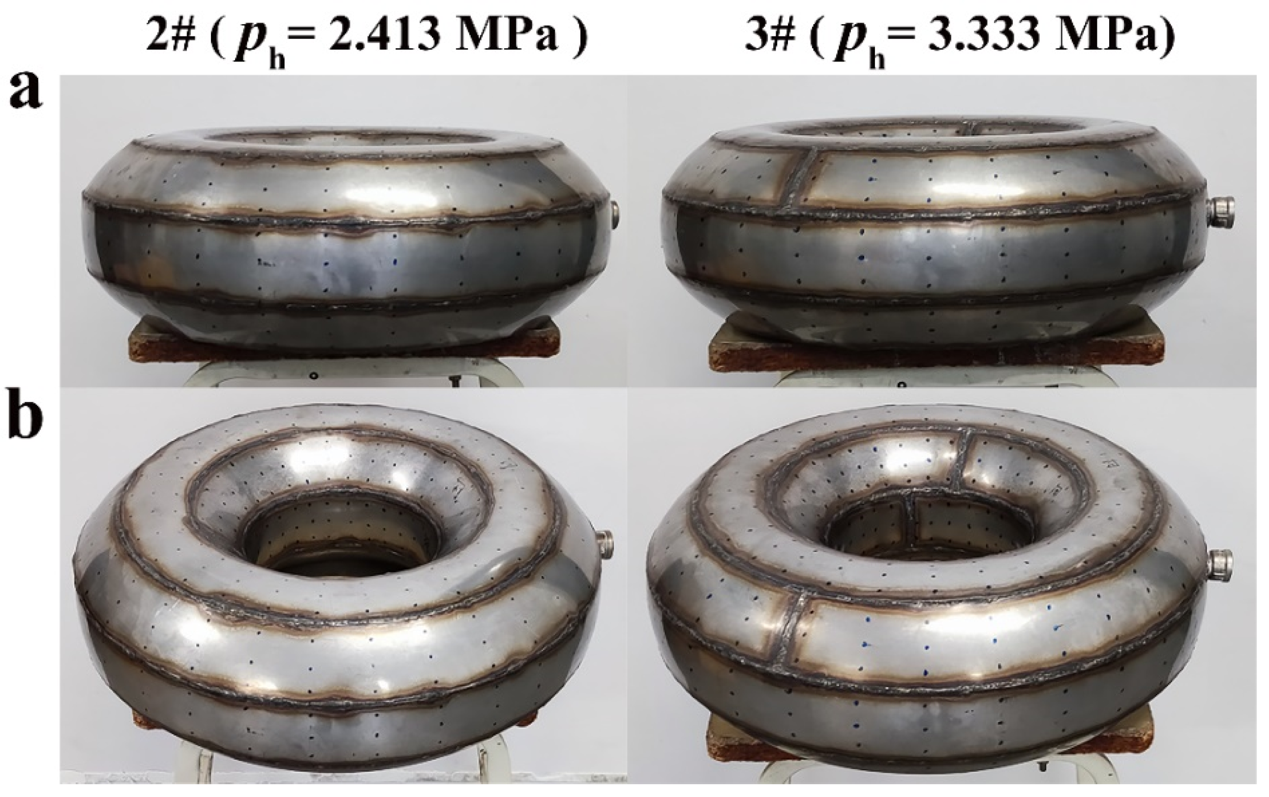
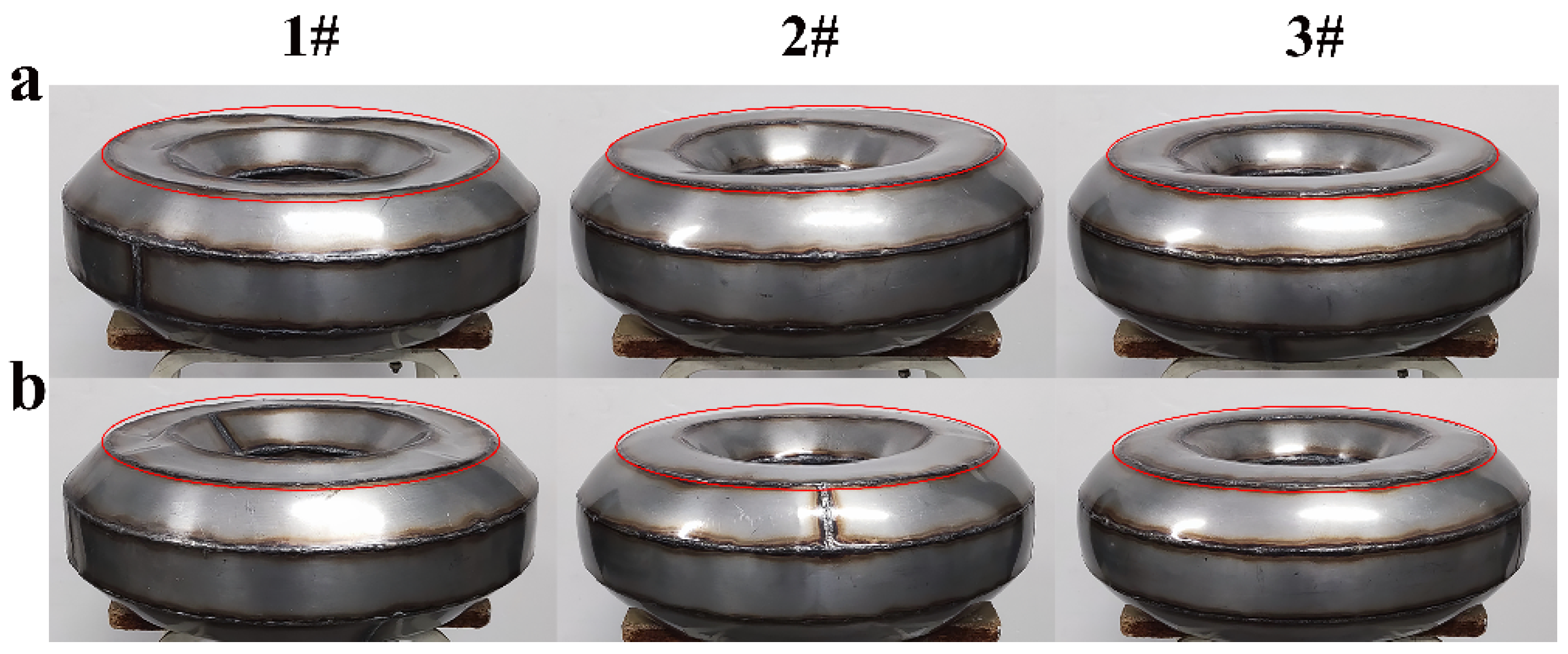
3.2.1. Geometrical Analysis of Three Manufactured Toroid Pressure Hulls

The obtained geometries and thicknesses of the three preformed toroids exhibit good accuracy and iterance of manufacturing. The geometrical deviations of the three preformed toroids from the nominal geometry of the black lines in Figure 1 are shown in Figure 13. As can be seen in Figure 13, most deviations range only from −2 to 2 mm. The probability density in the legends is concentrated around zero. Several local dimples were found on the pole circular plates (C) of the preformed toroids due to the welding deformation and residual stress. The statistical data on wall thicknesses are listed in Table 4. The thickness ranges from 1.054 to 1.062 mm for the 1# preformed toroid, 1.054 to 1.060 mm for the 2# preformed toroid, and 1.052 to 1.059 mm for the 3# preformed toroid. These slight ranges suggest a nearly uniform distribution of wall thickness. Comparing Figure 7 and Table 4, the results of the experimental points and the numerical observations are in good agreement.
The obvious plastic deformation is found for circular plates (C) and innermost frustum (D) because of the high distributed stress [43]. The geometrical deviations of the hydroformed toroids from the nominal geometry of the red lines in Figure 1 and from the preformed geometries in Figure 13 are shown in Figure 14. As can be seen in Figure 14, the maximum deformation is located in the middle of the pole circular plates (C). There is almost no deformation for welding lines because of the high stiffness. The deformation of the outmost cylinder (A) and outmost frustum (B) is small because of the low distributed stress. Comparing the geometrical deviations of the 2# hydroformed toroids and 3# hydroformed toroids, high hydroforming pressure leads to large plastic deformation. Comparing Figure 13 and Figure 14a, local dimple-shaped imperfections can be alleviated and finally eliminated through the hydroforming process. Such alleviation and elimination can be attributed to the principle of the hastening sphere [21,22,23,24,25,26]. As a result, a highly axisymmetric geometry of toroidal pressure hulls can be obtained from the hydroforming technique. These experimental findings confirm well the numerical observations in Figure 5.
The geometrical deformation is strongly associated with the thickness variations of hydroformed toroids. Thicknesses thinning ratios after the hydroforming of the two preformed toroids are shown in Figure 15. The thinning ratio is defined as the ratio of the thickness difference between preformed toroids and hydroformed toroids to the thickness of preformed toroid. As can be seen in Figure 15, the maximum thinning ratio is close to 0.8 for the 2# hydroformed toroids and is close to 1 for the 3# hydroformed toroid. The thinning is mainly attributed to the increased surface area caused by geometrical deformation. According to the principle of constant material volume, the larger the toroid surface area, the thinner the toroid wall. The minimum thinning ratio of both toroids are close to zero because of manufactured geometric imperfection. These experimental findings confirm well the numerical observations in Figure 6 and Figure 7. In addition, the similar findings of geometrical properties were obtained in the free hydroforming of ellipsoids [23,24,25,26], egg-shaped shells [35,36,37], and spheres [21,22].

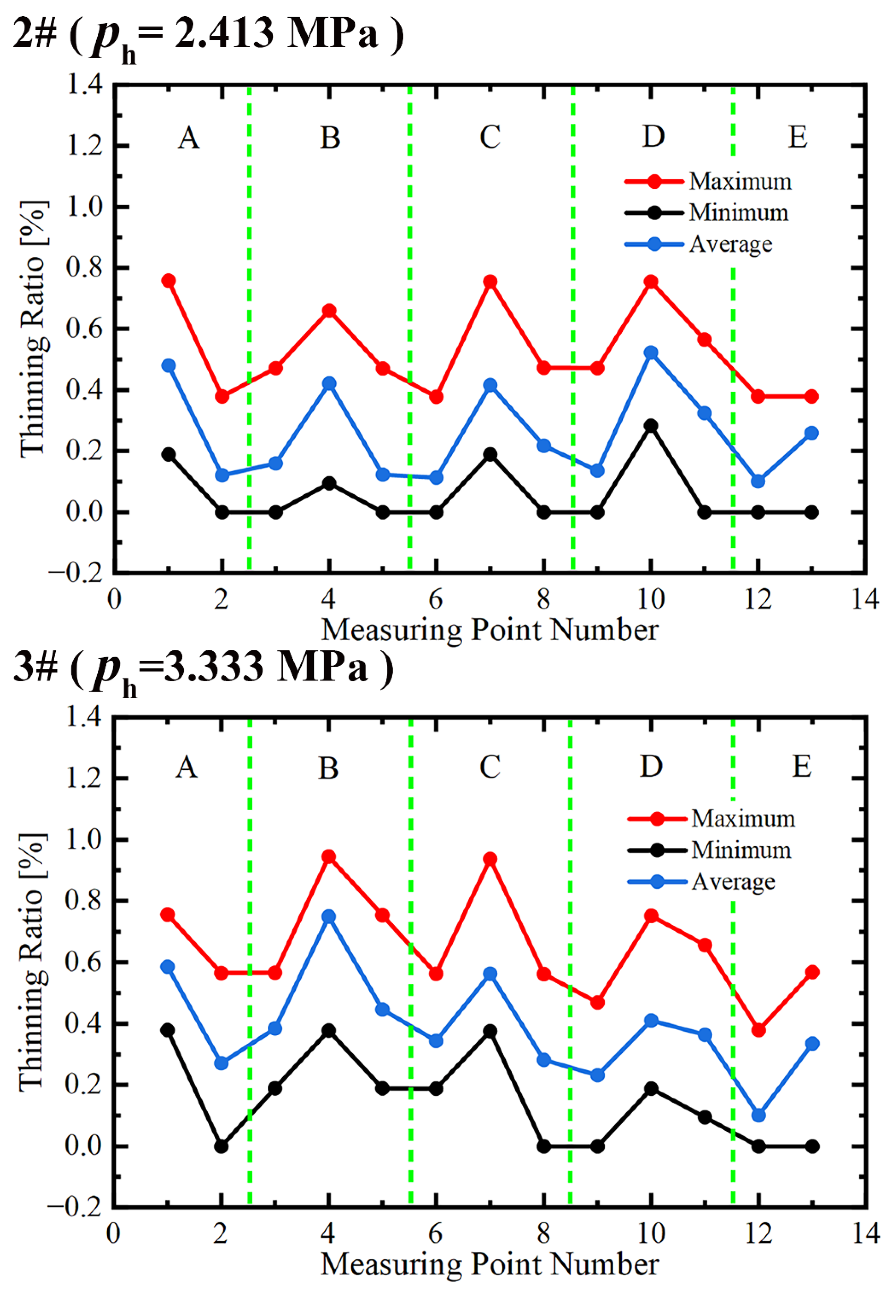
3.2.2. Mechanical Analysis of Three Manufactured Toroid Pressure Hulls

The applied pressure increases monotonically and quasi-statically until leakage during the hydroforming tests. The monotonical increase in pressure is mainly due to the material hardening and the curvature increasing. The pressure histories recorded from the hydroforming tests of the two preformed toroids are shown in Figure 16a. As can be seen in Figure 16a, the loading time is as long as 54 s for the 2# preformed toroid and is as long as 95 s for the 3# preformed toroid. The long time suggests a quasi-static process of the hydroforming test. The difference in the loading rates of the two preformed toroids results from the manual operation of the water pump.
Due to welding defects, a pinhole with a diameter of less than 1 mm can occur at the weld seam when the hydroforming pressure reaches a certain degree in the hydroforming process. This pinhole causes water to eject out of the shell and the pressure inside the shell cannot continue to increase. At this time, the water ejecting is called leakage, and hydroforming is finished. According to previous studies on pressure spherical shells with openings [52], a small hole has nearly no effect on the shell collapse strength under external pressure.
The maximum pressure at the end of each hydroforming test corresponds to the hydroforming pressure. The hydroforming pressure is 2.413 MPa for the 2# preformed toroid and 3.333 MPa for the 3# preformed toroid. The experimental data agree well with the numerical estimations in Figure 9a. It is inferred that an optimum toroid can be obtained if high-quality welding is conducted to avoid leakage. Photographs of the two hydroformed toroids after the hydroforming tests are shown in Figure 17. The weld seams can be clearly identified because the black oxide skin is not treated after the welding.
Similarly, the applied pressure increases monotonically and quasi-statically until the collapse during the hydrostatic tests. Two hydroformed toroids and one preformed toroid were tested to collapse. The pressure histories recorded from the hydrostatic tests of the three toroids are shown in Figure 16b. As can be seen in Figure 16b, the loading time is as long as 46 s for the 1# preformed toroid, as long as 62 s for the 2# hydroformed toroid, and as long as 64 s for the 3# hydroformed toroid. The long time suggests the quasi-static process of the hydrostatic test. The difference in the loading rates of the three toroids results from the manual operation of the water pump.
The maximum pressure of each hydrostatic test corresponds to the external collapse strength, which can be used to examine the loading capacity of toroidal pressure hulls. After the collapse strength, the applied pressure dropped suddenly due to the sudden decrease in the capacity of collapsed toroids. The external collapse strength is 0.458 MPa for the 1# preformed toroid, 0.729 MPa for the 2# hydroformed toroid, and 0.837 MPa for the 3# hydroformed toroid. Compared to the preformed toroids, the loading capacity of the hydroformed toroids increased by as much as 1.59–1.83 times. The experimental data agree well with the numerical estimations in Figure 9b.
The collapse modes of the tested toroids belong to the deformation of pole plates along the axis of revolution. Photographs of the two hydroformed toroids and one preformed toroid after the hydrostatic tests are shown in Figure 18. As can be seen in Figure 18, the deformation is nearly axisymmetric around the axis of revolution, which is consistent with the numerical estimations in Figure 10.

4. Conclusions

This study conducted a numerical and experimental investigation of the hydroforming and buckling of toroidal pressure hulls with octagonal cross-sections. The numerical estimations and experimental observations are consistent with each other. The following conclusions are drawn:
(1)
The cross-sections of hydroformed toroidal pressure hulls change gradually from a discrete octagon into a continuous circle as the hydroforming pressure increases. The wall thickness varies slightly, suggesting a nearly uniform distribution of hydroforming.
(2)
For the first two hydroforming cases and the last three hydroforming cases, the numerical collapse strength keeps constant. For the remaining hydroforming cases, the numerical collapse strength increases linearly and considerably with an increase in the hydroforming amplitude.
(3)
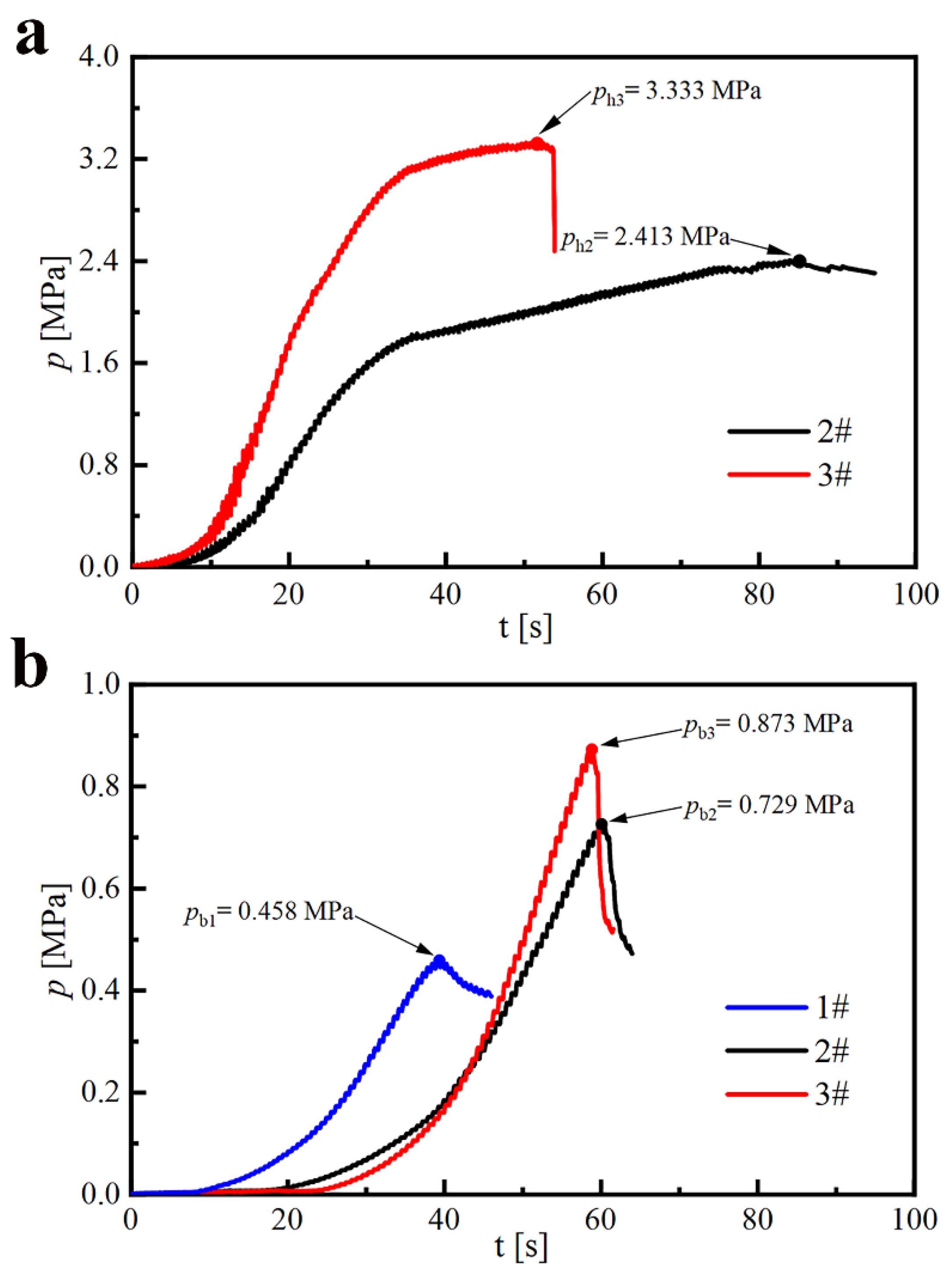
The experimental collapse strength is 0.458 MPa for preformed toroids and 0.729 MPa and 0.837 MPa for hydroformed toroids. Compared to the preformed toroids, the loading capacity of the hydroformed toroids increased by as much as 1.59–1.83 times.
(4)
The collapse modes of the tested toroids belong to the deformation of pole plates along the axis of revolution. The deformation is nearly axisymmetric around the axis of revolution, which is consistent with the numerical observations.

Author Contributions

X.L. and J.Z. equally contributed to this work. Conceptualization, C.D.; methodology, J.Z.; software, M.Z.; validation, F.W.; formal analysis, X.L. and J.Z.; investigation, X.L. and J.Z.; data curation, X.L. and C.D.; writing—original draft preparation, X.L.; writing—review and editing, J.Z.; All authors have read and agreed to the published version of the manuscript.

Funding

This work was supported by the National Natural Science Foundation of China (Grant Nos. 52071160 and 52071203).

Institutional Review Board Statement

Not applicable.

Informed Consent Statement

Not applicable.

Data Availability Statement

The data presented in this study are available on request from the corresponding author. The data are not publicly available due to privacy.

Conflicts of Interest

The authors declare no conflict of interest.

References

  1. Jiammeepreecha, W.; Chucheepsakul, S. Nonlinear Static Analysis of an Underwater Elastic Semi-Toroidal Shell. Thin-Walled Struct. 2017, 116, 12–18. [Google Scholar] [CrossRef]
  2. Zhang, J.; Wang, X.; Tang, W.; Wang, F.; Yin, B. Experimental and Numerical Buckling Analysis of Toroidal Shell Segments under Uniform External Pressure. Thin-Walled Struct. 2020, 150, 106689. [Google Scholar] [CrossRef]
  3. Pietraszkiewicz, W.; Konopińska, V. Junctions in Shell Structures: A Review. Thin-Walled Struct. 2015, 95, 310–334. [Google Scholar] [CrossRef]
  4. Wang, Z.R.; Hu, W.L.; Yuan, S.J.; Wang, X.S. Engineering Plasticity-Theory and Applications in Metal Forming; Higher Education Press: Beijing, China; John Wiley & Sons Singapore Pte., Ltd.: Singapore, 2018; pp. 355–356. [Google Scholar]
  5. Zhan, H.J.; Redekop, D. Vibration, Buckling and Collapse of Ovaloid Toroidal Tanks. Thin-Walled Struct. 2008, 46, 380–389. [Google Scholar] [CrossRef]
  6. Zhan, H.J.; Redekop, D. Static and Dynamic Loading of an Ovaloid Toroidal Tank. Thin-Walled Struct. 2009, 47, 760–767. [Google Scholar] [CrossRef]
  7. Lubis, A.; Su’Udi, A. Ring Stability of Underground Toroidal Tanks. AIP Conf. Proc. 2017, 1855, 040003. [Google Scholar] [CrossRef]
  8. Zingoni, A. Liquid-Containment Shells of Revolution: A Review of Recent Studies on Strength, Stability and Dynamics. Thin-Walled Struct. 2015, 87, 102–114. [Google Scholar] [CrossRef]
  9. Zingoni, A.; Enoma, N.; Govender, N. Equatorial Bending of an Elliptic Toroidal Shell. Thin-Walled Struct. 2015, 96, 286–294. [Google Scholar] [CrossRef]
  10. Zhang, J.; Di, C.; Wang, F.; Tang, W. Buckling of Segmented Toroids under External Pressure. Ocean Eng. 2021, 239, 109921. [Google Scholar] [CrossRef]
  11. Ross, C.T.F. A Conceptual Design of an Underwater Vehicle. Ocean Eng. 2006, 33, 2087–2104. [Google Scholar] [CrossRef]
  12. Ross, C.T.F. A Conceptual Design of an Underwater Missile Launcher. Ocean Eng. 2005, 32, 85–99. [Google Scholar] [CrossRef]
  13. Du, Q.; Cui, W.; Zhang, B. Buckling Characteristics of a Circular Toroidal Shell with Stiffened Ribs. Ocean Eng. 2015, 108, 325–335. [Google Scholar] [CrossRef]
  14. Du, Q.; Zou, G.; Zhang, B.; Wan, Z. Simplified Theoretical Solution of Circular Toroidal Shell with Ribs under Uniform External Pressure. Thin-Walled Struct. 2015, 96, 49–55. [Google Scholar] [CrossRef]
  15. Błachut, J. Buckling and First Ply Failure of Composite Toroidal Pressure Hull. Comput. Struct. 2004, 82, 1981–1992. [Google Scholar] [CrossRef]
  16. Galletly, G.D.; Blachut, J. Stability of Complete Circular and Non-Circular Toroidal Shells. J. Mech. Eng. Sci. 1995, 209, 245–255. [Google Scholar]
  17. Zou, G.; Peng, X.N.; Du, Q.H. Theoretical Solution and Essential Research of the Ring-Stiffened Toroidal Shell. J. Ship Mech. 2012, 16, 83–92. [Google Scholar]
  18. Du, Q.H.; Cui, W.C.; Wan, Z.Q. Nonlinear Finite Element Analysis of a Toroidal Shell with Ring-Stiffened RIBS. In Proceedings of the International Conference on Offshore Mechanics and Arctic Engineering—OMAE, Shanghai, China, 6–11 June 2010; Volume 2, pp. 759–765. [Google Scholar]
  19. Alves, L.M.; Martins, P.A.F. Forming of Thin-Walled Tubes into Toroidal Shells. J. Mater. Process. Technol. 2010, 210, 689–695. [Google Scholar] [CrossRef]
  20. Micari, F.; Ambrogio, G.; Filice, L. Shape and Dimensional Accuracy in Single Point Incremental Forming: State of the Art and Future Trends. J. Mater. Process. Technol. 2007, 191, 390–395. [Google Scholar] [CrossRef]
  21. Zhang, R.; Zhang, W.W.; Yuan, S.J. Research on Hydro-Forming of Spherical Shells with Different Preform Types. Int. J. Adv. Manuf. Technol. 2017, 92, 2631–2638. [Google Scholar] [CrossRef]
  22. Zhang, Q.; Wang, Z.R. Shape Improvement of a Dieless Hydro-Bulged Sphere Made of Hexagonal and Pentagonal Shaped Panels. J. Mater. Process. Technol. 2015, 220, 87–95. [Google Scholar] [CrossRef]
  23. Zhang, W.W.; Yuan, S.J. Reverse Geometric Modeling for Pre-Form Shape of Prolate Ellipsoid before Hydro-Forming. Int. J. Adv. Manuf. Technol. 2016, 88, 1903–1909. [Google Scholar] [CrossRef]
  24. Zhang, W.W.; Yuan, S.J. Research on Hydro-Forming of Combined Prolate Ellipsoidal Shell with Double Generating Lines. Int. J. Adv. Manuf. Technol. 2015, 82, 595–603. [Google Scholar] [CrossRef]
  25. Yuan, S.J.; Zhang, W.W.; Teng, B.G. Research on Hydro-Forming of Combined Ellipsoidal Shells with Two Axis Length Ratios. J. Mater. Process. Technol. 2015, 219, 124–132. [Google Scholar] [CrossRef]
  26. Zhang, W.W.; Teng, B.G.; Yuan, S. J Research on Deformation and Stress in Hydroforming Process of an Ellipsoidal Shell without Constraint. Int. J. Adv. Manuf. Technol. 2015, 76, 1555–1562. [Google Scholar] [CrossRef]
  27. Ruan, S.; Lang, L.; Ge, Y. Hydroforming Process for an Ultrasmall Bending Radius Elbow. Adv. Mater. Sci. Eng. 2018, 2018, 7634708. [Google Scholar] [CrossRef]
  28. Wang, Z.R. Shell and Tube Hydroforming: Mechanics of Dieless Closed Shell Hydro-Bulging; Higher Education Press: Beijing, China, 2018; pp. 343–364. [Google Scholar]
  29. Yuan, S.; Teng, B.; Wang, Z.R. A New Hydroforming Process for Large Elbow Pipes. J. Mater. Process. Technol. 2001, 117, 28–31. [Google Scholar] [CrossRef]
  30. Yuan, S.J.; Xu, Z.; Wang, Z.R.; Hai, W. The Integrally Hydro-Forming Process of Pipe Elbows. Int. J. Press. Vessel. Pip. 1998, 75, 7–9. [Google Scholar] [CrossRef]
  31. Yuan, S.; Wang, Z.R.; He, Q. Finite Element Analysis of Hydro-Forming Process of a Toroidal Shell. Int. J. Mach. Tools Manuf. 1999, 39, 1439–1450. [Google Scholar] [CrossRef]
  32. Teng, B.G.; Yuan, S.J.; Wang, Z.R. Effect of the Initial Structure on the Hydro-Forming of Toroidal Shells. J. Mater. Process. Technol. 2002, 123, 18–21. [Google Scholar] [CrossRef]
  33. Teng, B.G.; Yuan, S.J.; Wang, Z.R. Experiment and Numerical Simulation of Hydro-Forming Toroidal Shells with Different Initial Structure. Int. J. Press. Vessel. Pip. 2001, 78, 31–34. [Google Scholar] [CrossRef]
  34. Soni, A.; Vimal, J.; Sharma, A.K. Finite Element Analysis of Component Developed by Tube Hydro Forming. Int. J. Res. Eng. Appl. Sci. 2014, 1, 35–43. [Google Scholar]
  35. Zhang, J.; Dai, M.; Wang, F.; Tang, W.; Zhao, X. Buckling Performance of Egg-Shaped Shells Fabricated through Free Hydroforming. Int. J. Press. Vessel. Pip. 2021, 193, 104435. [Google Scholar] [CrossRef]
  36. Zhang, J.; Dai, M.; Wang, F.; Tang, W.; Zhao, X. Theoretical and Experimental Study of the Free Hydroforming of Egg-Shaped Shell. Ships Offshore Struct. 2022, 17, 257–267. [Google Scholar] [CrossRef]
  37. Zhang, J.; Cheng, P.; Wang, F.; Tang, W.; Zhao, X. Hydroforming and Buckling of an Egg-Shaped Shell Based on a Petal-Shaped Preform. Ocean Eng. 2022, 250, 111057. [Google Scholar] [CrossRef]
  38. Zhang, J.; Wang, F.; Wang, F.; Zhao, X.; Tang, W.; Chen, F. Buckling Properties of Bulged Barrels under External Pressure. Thin-Walled Struct. 2021, 168, 108226. [Google Scholar] [CrossRef]
  39. Zhang, J.; Liu, C.; Tang, W.; Wang, F.; Zhao, X.; Zhang, J.; Tang, L. Collapse of Barreled Frustums under External Hydrostatic Pressure. Mar. Struct. 2022, 84, 103218. [Google Scholar] [CrossRef]
  40. Zhang, J.; Liu, X.; Zhan, M.; Wang, F.; Zhao, X. Hydroforming and buckling of toroids with polyhedral sections. Ships Offshore Struct. 2022; 1–11, in press. [Google Scholar] [CrossRef]
  41. ISO 6892-1; Metallic Materials, Tensile Testing-Part-1: Method of Test at Room Temperature. ISO: Geneva, Switzerland, 2009; Volume 2009.
  42. Zhang, J.; Hua, Z.; Tang, W.; Wang, F.; Wang, S. Buckling of Externally Pressurised Egg-Shaped Shells with Variable and Constant Wall Thicknesses. Thin-Walled Struct. 2018, 132, 111–119. [Google Scholar] [CrossRef]
  43. Zhang, J.; Wang, X.; Tang, W.; Wang, F.; Zhu, Y. Non-Linear Collapse Behavior of Externally Pressurized Resin Toroidal and Cylindrical Shells: Numerical and Experimental Studies. Ships Offshore Struct. 2021, 16, 529–545. [Google Scholar] [CrossRef]
  44. Wang, Z.R.; Zeng, Y.S.; Yuan, S.J.; Zhang, S.H. The Research on the Plastic Deformation of the Hydrobulge Forming of Ellipsoidal Shells. Acta Mech. Solida Sin. 1998, 19, 259–264. [Google Scholar]
  45. Wang, Z.R.; Wang, T.; Kang, D.C.; Zhang, S.H.; Yi, F. The Technology of the Hydro-Bulging of Whole Spherical Vessels and Experimental Analysis. J. Mech. Work. Technol. 1989, 18, 85–94. [Google Scholar] [CrossRef]
  46. CCS. Rules for Construction and Classification of Diving Systems and Submersibles; China Classification Society: Beijing, China, 2013. [Google Scholar]
  47. Tang, W.; Wang, W.; Zhang, J.; Wang, S. Buckling of Cassini Oval Pressure Hulls Subjected to External Pressure. China Ocean Eng. 2019, 33, 503–508. [Google Scholar] [CrossRef]
  48. Wang, M.; Zhang, J.; Wang, W.; Tang, W. Linear and Nonlinear Elastic Buckling of Stereolithography Resin Egg-Shaped Shells Subjected to External Pressure. Thin-Walled Struct. 2018, 127, 516–522. [Google Scholar] [CrossRef]
  49. Zhang, W.W.; Yuan, S.J. Pre-Form Design for Hydro-Forming Process of Combined Ellipsoidal Shells by Response Surface Methodology. Int. J. Adv. Manuf. Technol. 2015, 81, 1977–1986. [Google Scholar] [CrossRef]
  50. Rathinam, N.; Prabu, B.; Anbazhaghan, N. Buckling Analysis of Ring Stiffened Thin Cylindrical Shell under External Pressure. J. Ocean Eng. Sci. 2021, 6, 360–366. [Google Scholar] [CrossRef]
  51. Foryś, P. Optimization of Cylindrical Shells Stiffened by Rings under External Pressure Including Their Post-Buckling Behaviour. Thin-Walled Struct. 2015, 95, 231–243. [Google Scholar] [CrossRef]
  52. Yu, M.H.; Wang, R.H.; Li, L.B. Research on the Ultimate Strength of Pressure Spherical Shell with Openings in Manned Deep-sea Submersible. Shipbuild. China 2005, 46, 92–96. [Google Scholar]
Figure 1. Schematic of toroidal pressure hulls with discrete octagonal cross-sections (black lines) and continuous circular cross-sections (red lines).
Metals 12 01475 g001
Figure 2. True stress versus true strain curves (a) obtained from uniaxial tensile tests of three flat coupons (b).
Metals 12 01475 g002
Figure 3. Finite-element and boundary conditions of toroidal pressure hull with discrete octagonal cross-section.
Metals 12 01475 g003
Figure 4. Three loading steps of toroidal pressure hulls: plastic deformation under internal hydroforming pressure ( p = p h ) (a); spring back under zero hydroforming pressure ( p = 0 ) (b); external collapse under external hydrostatic pressure ( p = p b ) (c).
Metals 12 01475 g004
Figure 5. Cross-sections (blue solid lines) of hydroformed toroidal pressure hulls after spring back subjected to various hydroforming pressures. Black solid lines correspond to discrete octagonal cross-sections before hydroforming in Figure 1; red lines correspond to continuous circular cross-sections with perfect geometry.
Metals 12 01475 g005
Figure 6. Thicknesses thinning ratio of toroidal pressure hulls after spring back subjected to various hydroforming pressures.
Metals 12 01475 g006
Figure 7. (ae) Thicknesses thinning ratio of toroidal pressure hulls under various hydroforming pressures.
Metals 12 01475 g007
Figure 8. Contour plots of equivalent stress (a), plastic strain (b), and wall thickness (c) for the nominal geometry.
Metals 12 01475 g008
Figure 9. Internal hydroforming pressures (a) and external collapse strengths (b) of toroidal pressure hulls under various hydroforming amplitudes ( Δ B ); hydroforming amplitudes ( Δ B ) are depicted in Figure 5. # is the number of the pressure hulls.
Metals 12 01475 g009
Figure 10. Applied pressure–arc length curves of toroidal pressure hulls under hydroforming pressures of 0 MPa (a), 3 MPa (b), and 5 MPa (c), along with several representative deformed geometries. Zero hydroforming pressure corresponds to discrete octagonal cross-sections before hydroforming in Figure 1.
Metals 12 01475 g010
Figure 11. Manufacturing flowchart of toroidal pressure hull with discrete octagonal cross-section: (a) blank cutting, (b) cut blank inspecting, (c) cut blank bending, (d) bent blank inspecting, (e) bent blank assembling, and (f) bent blank welding.
Metals 12 01475 g011
Figure 12. Experimental flowchart of toroidal pressure hull: (a) surface scanning of preformed toroid, (b) thickness measuring of preformed toroid, (c) internal hydroforming of preformed toroid, (d) thickness measuring of hydroformed toroid, (e) surface scanning of hydroformed toroid, and (f) hydrostatic testing of hydroformed toroid.
Metals 12 01475 g012
Figure 13. Geometrical deviations of preformed toroids from nominal geometry of black lines in Figure 1.
Metals 12 01475 g013
Figure 14. Geometrical deviations of hydroformed toroids from nominal geometry of red lines in Figure 1 (a) and from preformed geometries in Figure 13 (b).
Metals 12 01475 g014
Figure 15. Thicknesses thinning ratio after hydroforming of two preformed toroids.
Metals 12 01475 g015
Figure 16. Pressure histories recorded from hydroforming tests of two preformed toroids (a) and from hydrostatic tests of two hydroformed toroids and one preformed toroid (b).
Metals 12 01475 g016
Figure 17. Photographs of two hydroformed toroids after hydroforming tests: (a) front view and (b) isometric view.
Metals 12 01475 g017
Figure 18. Photographs of two hydroformed toroids and one preformed toroid after hydrostatic tests: (a) main view and (b) rear view.
Metals 12 01475 g018
Table 1. Geometrical dimensions of toroidal pressure hulls.
a / m m r / m m R / m m t / m m
57.4751501.058
Table 2. Material properties of 304 stainless steel.
Sample E / G P a μ σ y / M P a K
SC1198.20.292501566.3
SC2197.50.302521518.7
SC3197.80.302401578.9
AVE197.80.302471554.6
E = Young′s modulus; μ = Poisson′s ratio; σ y = yield stress; K = strength coefficient.
Table 3. Maximum vertical deformations and external collapse strengths of toroidal pressure hulls under various internal hydroforming pressures.
p h / M P a Δ B / m m p b / M P a L / W Δ B / B p b / p i
000.472000.405
10.8890.4891.0260.2640.419
1.51.7190.5081.0480.5110.435
22.3490.6291.0600.6980.539
2.52.7740.7761.0710.8240.665
33.0740.9051.0740.9130.775
3.53.3581.0351.0710.9980.887
43.6171.0861.0691.0750.931
4.53.8501.1121.0681.0430.953
54.7121.1441.0651.3990.981
p h = internal hydroforming pressure; Δ B = maximum vertical deformation; p b = external collapse strength; L = length of hydroformed toroidal pressure hulls; W = width of hydroformed toroidal pressure hulls; B = ideal deformation (3.366 mm); p i = external collapse strength of toroidal pressure hulls with continuous circular cross-sections (1.167 MPa).
Table 4. Measured wall thicknesses of three preformed toroids.
Measuring Point
Number
t / m m
1#2#3#
11.054 (N/A)1.057 (0.481)1.056 (0.586)
21.054 (N/A)1.058 (0.120)1.055 (0.274)
31.060 (N/A)1.058 (0.138)1.053 (0.384)
41.060 (N/A)1.058 (0.422)1.052 (0.749)
51.060 (N/A)1.058 (0.122)1.052 (0.447)
61.060 (N/A)1.058 (0.113)1.059 (0.345)
71.060 (N/A)1.058 (0.416)1.058 (0.564)
81.060 (N/A)1.058 (0.217)1.059 (0.282)
91.062 (N/A)1.059 (0.122)1.058 (0.232)
101.062 (N/A)1.060 (0.523)1.058 (0.410)
111.062 (N/A)1.060 (0.324)1.058 (0.363)
121.056 (N/A)1.054 (0.101)1.055 (0.101)
131.056 (N/A)1.055 (0.259)1.054 (0.335)
Note: Values in parentheses indicate thicknesses thinning ratio of hydroformed toroids. No hydroforming test for 1# preformed toroid.
Publisher’s Note: MDPI stays neutral with regard to jurisdictional claims in published maps and institutional affiliations.

