1. Introduction
Nitinol, a binary alloy of titanium and nickel, is one of the best-known smart materials. This is a temperature-sensitive alloy capable of realizing reversible diffusion-free thermoelastic phase transformations between two phases: high-temperature austenitic and low-temperature martensitic. The alloy can realize shape memory effect and superelasticity effect due to the thermoelastic transformation phenomenon [
1,
2]. This alloy was patented in 1965 and used in the industry for the first time in 1969 as a material for thermomechanical coupling of pipelines in hydraulic systems of F-14 fighters [
3,
4].
Further development of science and technology has expanded the Nitinol application. The alloy is currently applied in automotive, aerospace, and other industries as a material for thermal actuators and other devices of various purposes [
3,
5,
6,
7,
8]. Nitinol has also found its application in various fields of medicine due to its excellent biocompatibility because of the presence of oxide layers on the surface, consisting mainly of titanium dioxide [
9,
10,
11,
12,
13]. In orthopedics, Nitinol is used as a material for medical staples and other implants to treat various diseases of the skeletal system. In dentistry, the alloy is used as braces, in cardiology—as stents, artificial heart valves, pacemakers, and many other medical products [
3,
14,
15,
16,
17].
The development of additive technologies allows expanding Nitinol application as a smart material. Additive technologies make it possible to fabricate products with complex geometry that cannot be produced by classical machining methods. This may help to solve a number of problems including those in the medical sphere. In addition, it is noted that the use of additive technologies does not have a negative impact on the level of biocompatibility of the alloy. It is noted that the use of additive technologies with laser scanning (for example, SLM) improves the level of biocompatibility of the resulting structures, due to a thicker oxide film on the surface [
18,
19].
One of these problems is related to implants for various purposes. Today, most implants are fabricated from materials with stiffness higher than that of human bone tissue. The elastic modulus of a human cortical bone is 12–18 GPa, while the elastic modulus of a cancellous (trabecular) bone equals 0.1–5 GPa [
20,
21,
22,
23,
24,
25]. In turn, the elastic modulus of titanium and its alloys, of which most implants are made, is several times higher: 102–104 GPa for pure titanium, 110–114 GPa for Ti-6Al-4V alloy, and 50 to 100 GPa for other applied titanium alloys [
20,
25,
26,
27,
28].
Due to high stiffness, an implant carries a significant body load, which reduces a load on the bone around the implant. Reduced bone loading, in turn, can lead to bone resorption at the bone–implant interface, ingress of wear particles with subsequent inflammation and gradual loosening and detachment of the implant. In the literature, this phenomenon is known as stress shielding effect [
22,
29,
30]. There is a possibility of circulation of wear particles in the body (with their detection in the bone marrow, lymphatic system), followed by the induction of cytotoxicity and neoplasms [
28,
31].
This problem can be solved by reducing stiffness of the implant material to a level comparable to the stiffness of a human bone. Nitinol is one of the promising materials in this field. The Young’s modulus of Nitinol in martensite is 30–40 MPa, in austenite—75–83 MPa [
3,
14]. These values are clearly lower than those of the Ti-6Al-4V alloy, but still exceed the elastic modulus of a human bone. As an alternative, the Young’s modulus of Nitinol can be reduced using lattice structures with a certain level of porosity, which are fabricated by the SLM technique. An increased porosity significantly reduces the Young’s modulus of the fabricated structures. In [
22], this idea was confirmed by computer simulation. This approach has been described in papers [
30,
32,
33,
34] where lattice structures with low elastic modulus values were obtained through the use of porous structures with the geometry of single cells based on struts with different levels of porosity. Values of elasticity modulus have been obtained close to those of the human cortical bone. However, values were not achieved close to those of the human trabecular bone.
The existence of a relationship between the topology of a unit cell of the lattice structure and the properties of the alloy was noted in [
30]. Furthermore, in [
24], it was noted that a computer simulation can be implemented to predict the behavior of TiNi samples with different levels of porosity and geometry. In turn, in our work [
35], using computer simulation, the theoretical possibility of controlling the properties of the lattice structure, including the values of the modulus of elasticity, was confirmed not only by changing the porosity, but also by changing the geometry of a unit cell of the lattice structure.
Apart from the implant stiffness problem, there is also the problem of implant detachment due to the constant positive Poisson’s ratio along the implant. When the implant with a constant positive Poisson’s ratio is used under cyclic compression–extension loading conditions, one side of the implant will be pressed against the bone at the interface, while the other, on the contrary, will be drawn aside. The latter side is more susceptible to surface damage. Besides, the implant drawn aside allows wear particles to penetrate into the space between the implant and the bone, causing the patient’s immune system to react to the foreign body, which results in inflammatory bone loss [
29,
36].
This problem can be solved using complex implants, where the side drawn away from the bone will have a negative Poisson’s ratio. Due to this, the side will exert additional pressure on the bone-implant interface when used cyclically, mechanically stimulating bone growth and blocking the possibility of bone tissue detachment and inflammation [
36].
The priority task can be clearly defined based on the above-described problems: development and fabrication of TiNi alloy lattice structures with low elastic modulus and negative Poisson’s ratio. The solution to this problem must be considered in a complex way, using the possibilities of computer simulation for the initial programming of the properties of the lattice structure, and production of this lattice structure by the SLM method from TiNi alloy powder. Accordingly, it is necessary to develop a complete methodology for obtaining lattice structures from the TiNi alloy, which makes it possible to obtain products for various purposes with different properties.
This paper presents an integrated approach to solving the described problem, consisting of the implementation of several successive stages: computer simulation of a lattice structure for programming its characteristics; fabrication of a lattice structure by the SLM method from TiNi alloy powder; study of the resulting lattice structures. The study involves the determination of mechanical characteristics and the possibility to implement the superelasticity phenomenon useful in the advanced use of the fabricated structures in implants subjected to cyclic loads. Besides, the study allows checking the simulated parameters of lattice structures for compliance with the actual parameters and the general capability to fabricate TiNi alloy lattice structures with negative Poisson’s ratio by the SLM technique. Thus, the take home message of this work is the experimental confirmation of the developed technique for obtaining lattice structures from the TiNi alloy with programmable properties—a low value of the elastic modulus and a negative Poisson’s ratio.
2. Materials and Methods
Figure 1 shows the block diagram that explain the workflow of the present study, consisting of several main steps—computer simulation, fabrication, and study of the resulting lattice structure.
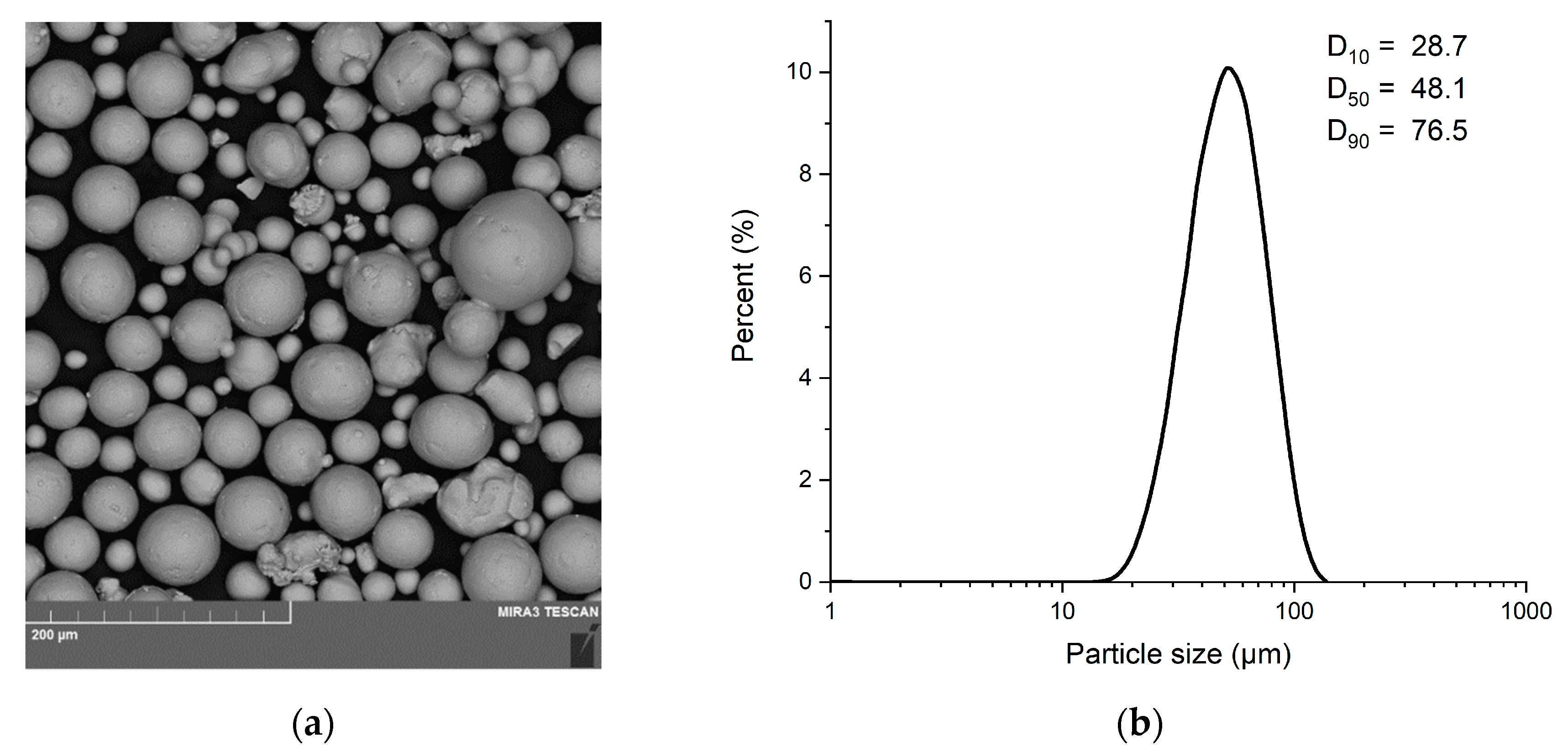
Samples were fabricated from spherical powder of TiNi alloy (with atomic percent of 49% and 51% for Ti and Ni, respectively) by CNPC Powder, Shanghai, China, using the electrode induction melting gas atomization method (EIGA). A SEM image of the alloy powder is shown in
Figure 2a.
Figure 2b presents the powder particle size.
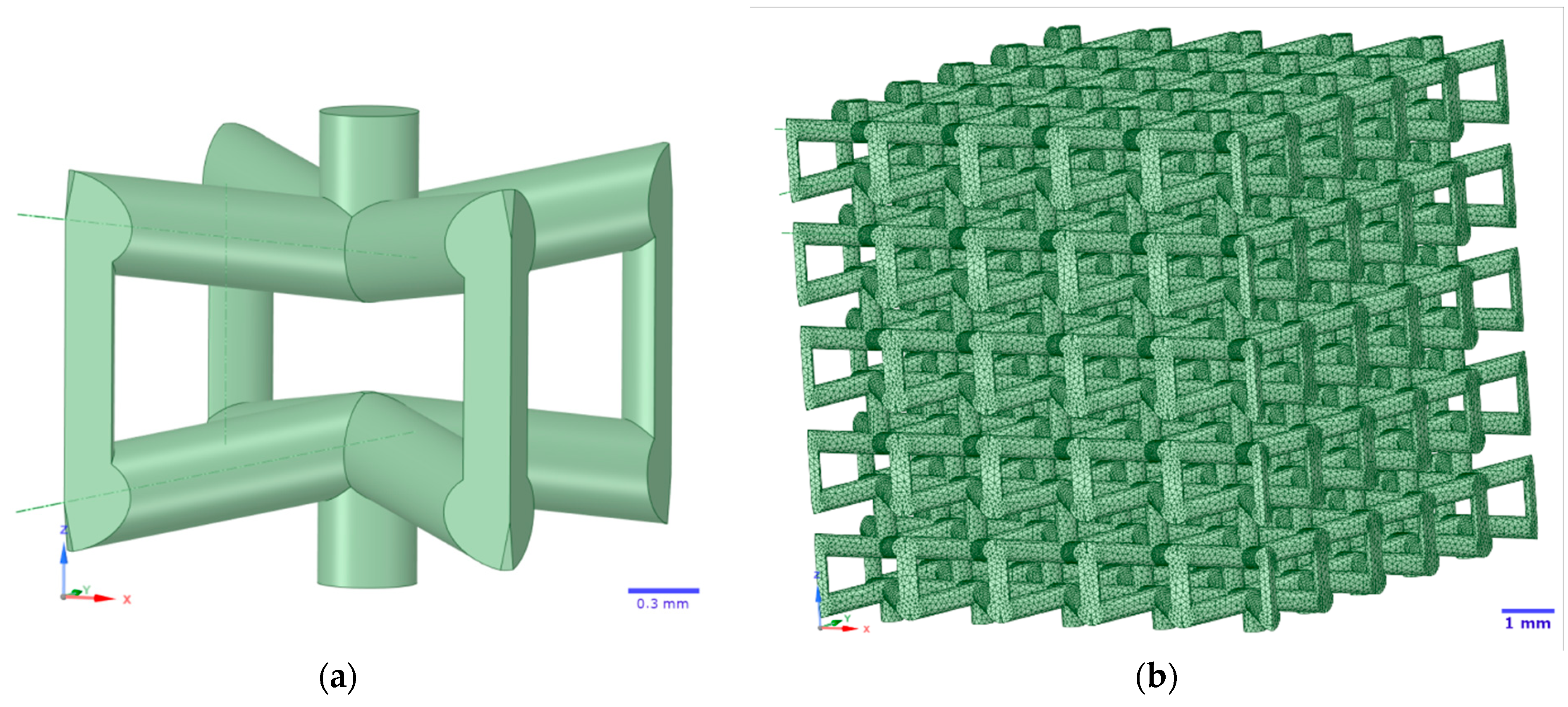
A single unit cell with negative Poisson’s ratio was simulated with the ANSYS 2019 R2 SpaceClaim software package (ANSYS 2019 R2, Ansys Inc., Canonsburg, PA, USA). This single unit cell topology was named Type 5. The single unit cell has dimensions of 2 mm × 2 mm × 2 mm and 80% porosity. A lattice structure consisting of 5 unit cells on three axes, i.e., 5 × 5 × 5 cells with total dimensions of 10 mm × 10 mm × 10 mm, was generated on the basis of the simulated single unit cell. A Type 5 single cell with negative Poisson’s ratio and the lattice structure itself are shown in
Figure 3a,b, respectively. The mechanical characteristics of the simulated lattice structure with 5 × 5 × 5 unit cells (Young’s modulus (E), shear modulus (G), and Poisson’s ratio) were determined by computer simulation of compression experiment with static load in elastic region, using ANSYS 2019 R2 SpaceClaim software package. Initial simulation data: Young’s modulus of austenite—77 GPa, Young’s modulus of martensite—30 GPa, Poisson’s ratio—0.33, shear modulus—29 GPa, density—6500 kg/m
3. To determine Young’s modulus, the normal displacement boundary condition without friction was applied to the lower faces of the lattice structure and the small displacement boundary condition was applied to the upper faces. For shear modulus, the normal displacement boundary condition without friction was applied to the lower and upper faces of the lattice structure, and the small displacement boundary condition was applied to the side faces.
The structures were processed by the Materialise Magics software package (Magics 25, Materialise NV, Leuven, Belgium) for fabrication and preparation for mechanical and other tests. The bases sized 10 mm × 10 mm × 6 mm and 10 mm × 10 mm × 3 mm were added to the lattice structure at the top and bottom.
Six lattice structures (3 structures with 10 mm × 10 mm × 6 mm bases and 3 structures with 10 mm × 10 mm × 3 mm bases) were fabricated by the SLM technique using the SLM280HL system (SLM Solutions GmbH, Lübeck, Germany). The system is equipped with an ytterbium fiber laser with a maximum power of 400 W, a wavelength of 1070 nm, a minimum laser beam diameter of 80 µm, and a maximum scanning rate of 15 m/s. The structures were fabricated in inert gas atmosphere (argon). The fabrication process parameters: laser power—200 W, scanning rate—925 mm/s, distance between laser passes—0.08 mm, layer thickness—0.03 mm.
Porosity of the fabricated lattice structures was calculated by formula (1) [
25,
37,
38]:
where, p* is lattice structure density, p
s is density of the material from which the lattice structure was fabricated.
The initial powder and the fabricated lattice structures were visually examined using TESCAN Mira 3 LMU (TESCAN, Brno, Czech Republic) scanning electron microscope (SEM) with secondary electrons (SE) and backscattered electrons (BSE). Phase composition of the initial powder and the fabricated samples was determined using Bruker D8 Advance X-ray diffraction (XRD) meter (Bruker, Bremen, Germany), using Cu-Kα (λ = 1.5418 Å). Transformation temperatures were determined using a high-temperature differential scanning calorimeter DSC 404 F3 Pegasus by NETZSCH-Gerätebau GmbH, Selb, Germany. The heating rate in argon atmosphere was 5 K/min.
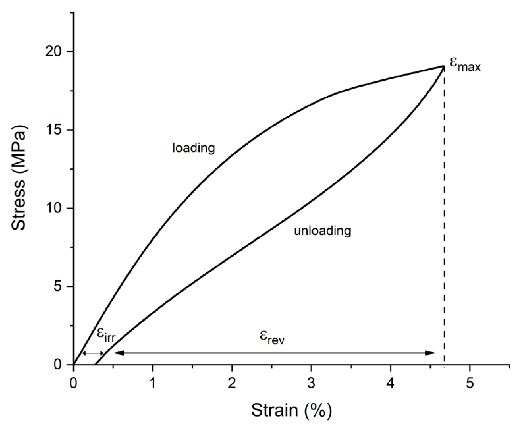
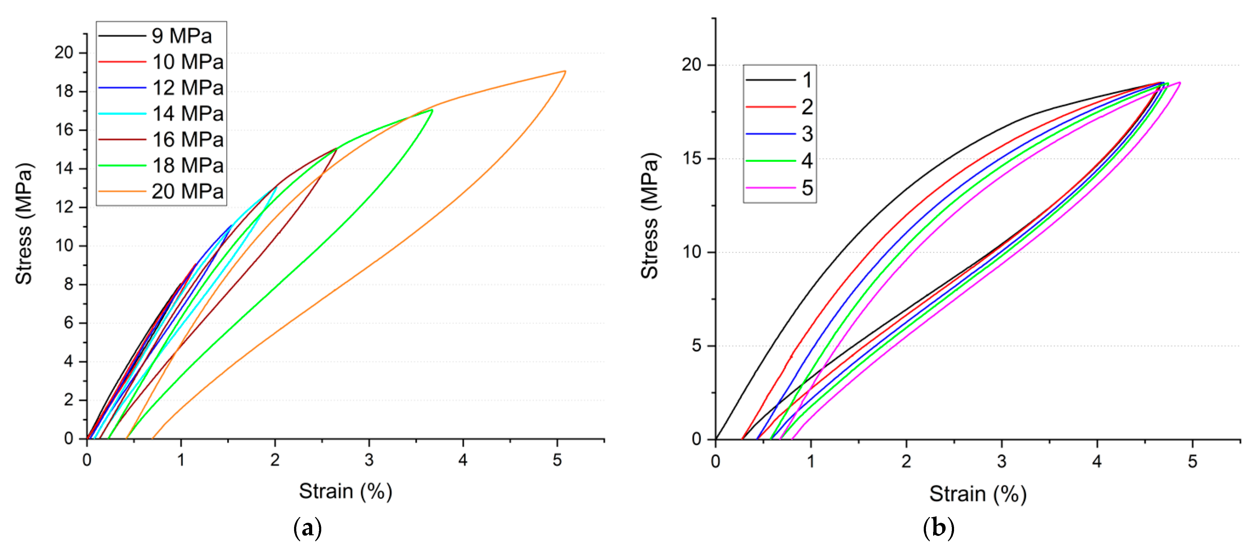
Compression test and cycling in compression were carried out using a Zwick/Roell Z100 single-axis floor-mounted testing machine (Zwick/Roell, Ulm, Germany). The compression direction was perpendicular to the building direction (BD). Cycling loading stress varies from 9 to 20 Mpa. An example of reversible and irreversible strain during cycling under the superelasticity effect is shown in
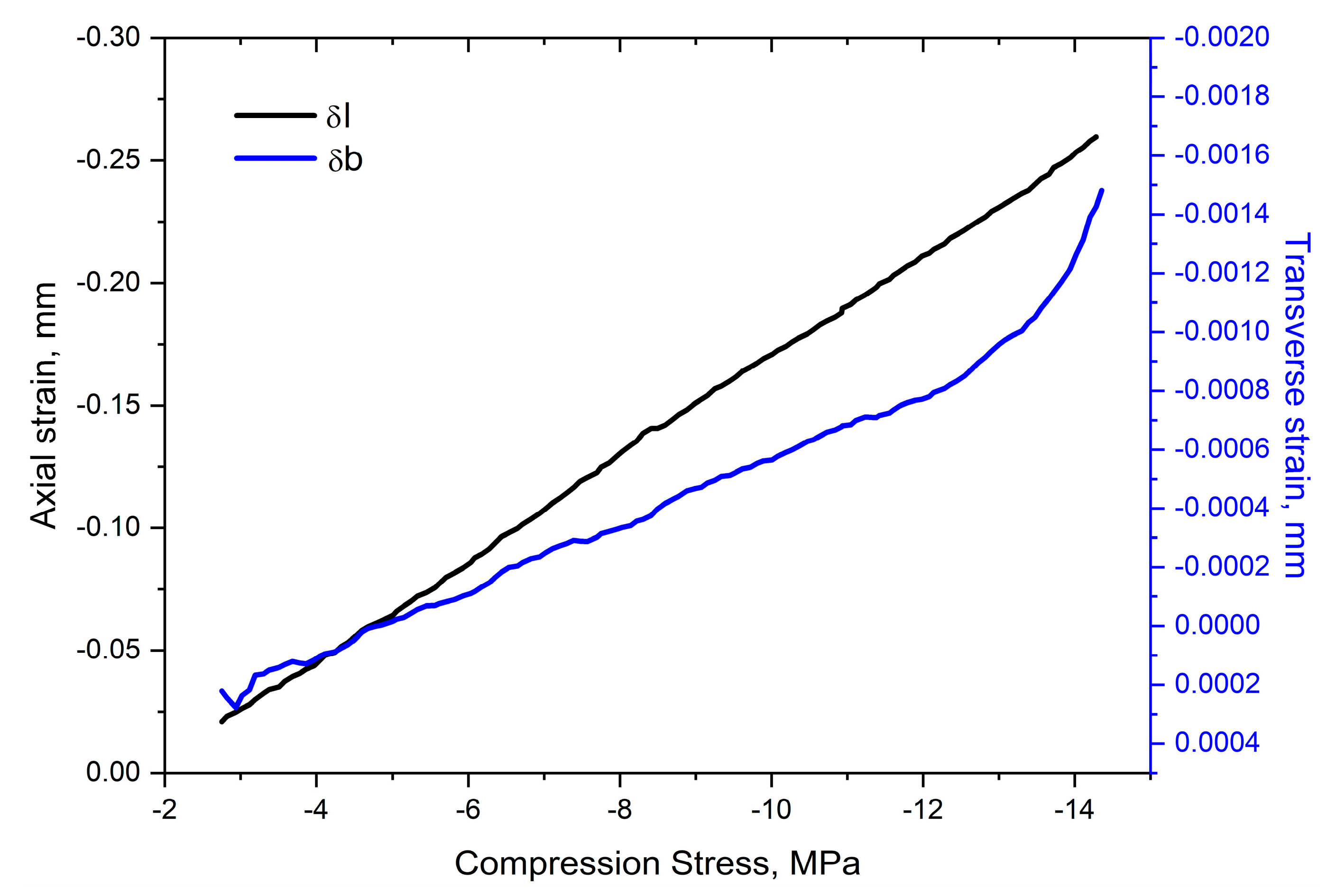
Figure 4. A Gleeble 3800 testing machine (Dynamic Systems Inc., Austin, TX, USA) with a strain gauge type hot zone transducer (Hot Zone L-Strain) and crosswise LVDT type gauge (C-Gauge) was used to determine longitudinal strain and lateral strain of compressed samples for Poisson’s ratio calculation. The Poisson’s ratio was calculated by formula (2) [
39] based on the obtained data:
where, ε is relative longitudinal (axial) strain of the sample calculated as δl/l (l is sample reference length), ε
t is relative lateral strain of the sample calculated as δb/b (b is sample width) [
40].
4. Discussion
The fabricated lattice structures, in terms of their properties, matched the initial simulation results in general. Deviations in porosity of the structures (69.8% porosity vs. 80% assumed in the simulation) are a specific feature of the fabrication technique and the SLM system itself. This also can explain some excess in the resultant values of elastic modulus specified in
Table 2. It can be noted that the obtained values fall within the elastic modulus interval for a human trabecular bone. However, porosity of the fabricated lattice structure should be reduced to achieve the proper elastic modulus of a cortical bone. In addition, the obtained values of the porosity and modulus of elasticity of lattice structure are lower than the values obtained in other works. For example, in [
32], the smallest Young’s modulus was 6.4 GPa with the porosity of the structure 59.09%. In [
24], it was 9 GPa with the porosity 58%, and in [
30], the lowest value of the modulus of elasticity was 16.5 GPa with the porosity 65%. It should be noted that the compression deformation is rather low, averaging less than 22 MPa. This value is lower than that of a human cortical bone for which it is estimated around 153–205 MPa [
21]. The resultant negative values of the Poisson’s ratio are numerically very different from the values obtained during simulation. In this case, the obtained results are probably influenced both by a higher porosity and by errors that may arise when determining strains of a sample.
As previously noted, a variation in the alloy transformation temperatures was caused by evaporation of nickel from the TiNi alloy powder during SLM process. Intensive evaporation of nickel is due to the difference between the boiling points of nickel and titanium: nickel has a boiling point of 2913 °C, while the titanium boiling point equals 3287 °C. It is known that a variation in nickel content in the TiNi alloy greatly affects the transformation temperatures of the alloy. A 0.1 at. % increase in nickel content leads to a 10 K decrease in the transformation temperatures. On the contrary, a decrease in nickel content leads to an increase in the transformation temperatures [
46,
47,
48]. Accordingly, a decreased nickel content in the alloy after lattice structure fabrication by the SLM technique led to an increase in A
p and A
f temperatures.
The studies of the samples’ superelasticity showed a rather high durability of the sample under high loads. The total accumulated irreversible strain amounted to 1.2% after 11 cycles (see
Table 3) provided that the last five cycles were conducted under a load being close to the ultimate compression strain. The test temperature was lower than temperature Af of the fabricated lattice structures (see
Table 1), which shall also negatively affect the possibility of reversible strain, and lead to incomplete recovery and an increase in irreversible strain.
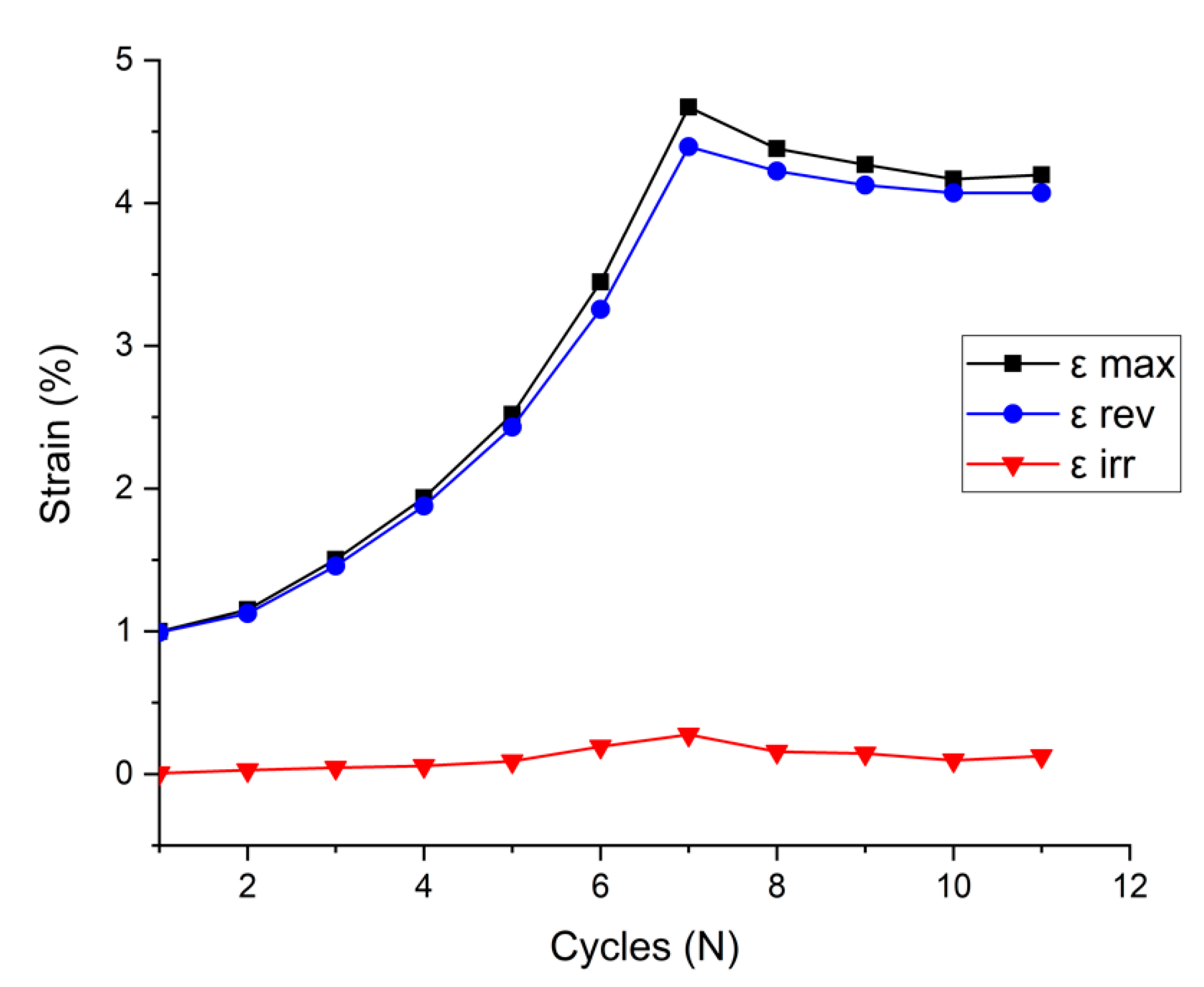
The curve of strain values as a function of the cycle (
Figure 13) was plotted on the basis of the data in
Table 3. According to the figure, both reversible and irreversible strains rise proportionally to stress increase. As noted earlier, the maximum value of all strains was obtained during cycle 7. After that, despite the maintained stress of 20 MPa, there was a slight drop in the maximum, reversible, and irreversible strain. This may be due to stabilization of the sample superelastic response. The stabilization effect of shape memory and superelasticity response of the SLM structures was previously noted in several works [
24,
30,
33].
Some limitations of this work should be noted. Firstly, the computer simulation did not consider the behavior of the lattice structure in the plastic region due to the need to determine the characteristics only in the elastic zone. Secondly, only one unit cell topology was considered in this work. Thirdly, only a part of the transformation temperatures of alloy is determined in the work, due to the technological features of the equipment. On the issue of accuracy, one can note the general repeatability of the results obtained for the samples. Moreover, the samples should be further tested by the cycling method but at different temperature conditions, namely at a temperature close to human body temperature: 36.6–37 °C. At the same time, it should be taken into account that the results of the experiments, when repeated, may vary depending on the initial powder (its quality, chemical composition), the SLM system used, and the parameters of the manufacturing process.
Author Contributions
Conceptualization, E.F. and A.O.; methodology, E.F. and A.O.; software, A.O. and A.R.; formal analysis, E.F.; investigation, E.F., N.G. and S.K.; writing—original draft preparation, E.F.; writing—review and editing, E.B.; project administration, A.P.; funding acquisition, E.F. and A.P. All authors have read and agreed to the published version of the manuscript.
Funding
The reported study was funded by RFBR according to the research project № 20-38-90031.
Institutional Review Board Statement
Not applicable.
Informed Consent Statement
Not applicable.
Data Availability Statement
The data presented in this study are available on request from the corresponding author.
Conflicts of Interest
The authors declare no conflict of interest.
References
- Rao, A.; Srinivasa, A.R.; Reddy, J.N. Design of Shape Memory Alloy (SMA) Actuators; Springer: Berlin/Heidelberg, Germany, 2015. [Google Scholar]
- Patel, S.K.; Swain, B.; Roshan, R.; Sahu, N.K.; Behera, A. A brief review of shape memory effects and fabrication processes of NiTi shape memory alloys. Mater. Today Proc. 2020, 33, 5552–5556. [Google Scholar] [CrossRef]
- Jani, J.M.; Leary, M.; Subic, A.; Gibson, M.A. A review of shape memory alloy research, applications and opportunities. Mater. Des. 2014, 56, 1078–1113. [Google Scholar] [CrossRef]
- Mantovani, D. Shape memory alloys: Properties and biomedical applications. JOM 2000, 52, 36–44. [Google Scholar] [CrossRef]
- Oehler, S.D.; Hartl, D.J.; Lopez, R.; Malak, R.J.; Lagoudas, D.C. Design optimization and uncertainty analysis of SMA morphing structures. Smart Mater. Struct. 2012, 21, 094016. [Google Scholar] [CrossRef]
- Stoeckel, D.; Waram, T. Use of Ni-Ti Shape Memory Alloys for Thermal Sensor-Actuators. Active and Adaptive Optical Components; Ealey, M.A., Ed.; Cambridge University Press: Cambridge, UK, 1992; Volume 1543, p. 382. [Google Scholar]
- Sharma, K.; Srinivas, G. Flying smart: Smart materials used in aviation industry. Mater. Today Proc. 2020, 27, 244–250. [Google Scholar] [CrossRef]
- Pepper, S.V.; DellaCorte, C.; Noebe, R.D.; Hall, D.R.; Glennon, G. Nitinol 60 as a material for spacecraft triboelements. In Proceedings of the 13th European Space Mechanisms and Tribology Symposium, Vienna, Austria, 23–25 September 2009. [Google Scholar]
- Marchenko, E.S.; Baigonakova, G.A.; Yasenchuk, Y.F.; Chekalkin, T.L.; Volinsky, A.A. Structure, biocompatibility and corrosion resistance of the ceramic-metal surface of porous nitinol. Ceram. Int. 2022, 48, 1–10. [Google Scholar] [CrossRef]
- Chen, R.; Feng, Y.; Yan, K.; Zhang, G. Study on Phase Transformation and Electrochemical Corrosion of TiNi Alloy Formed by Laser Solid Forming. Metals 2022, 12, 1024. [Google Scholar] [CrossRef]
- Nazarov, D.; Rudakova, A.; Borisov, E.; Popovich, A. Surface modification of additively manufactured nitinol by wet chemical etching. Materials 2021, 14, 7683. [Google Scholar] [CrossRef]
- Shishkovsky, I.; Volova, L.; Kuznetsov, M.; Morozov, Y.; Parkin, I. Porous biocompatible implants and tissue scaffolds synthesized by selective laser sintering from Ti and NiTi. J. Mater. Chem. 2008, 18, 1309–1317. [Google Scholar] [CrossRef]
- Dadbakhsh, S.; Speirs, M.; Kruth, J.-P.; Van Humbeeck, J. Influence of SLM on shape memory and compression behaviour of NiTi scaffolds. CIRP Ann. CIRP 2015, 64, 209–212. [Google Scholar] [CrossRef] [Green Version]
- Brailovski, V.; Prokoishkin, S.; Terriault, P.; Trochu, F. Shape Memory Alloys: Fundamentals, Modeling and Applications; ETC (Ecole de technologie superieure): Montreal, Canada, 2003. [Google Scholar]
- Stoeckel, D. Nitinol medical devices and implants. Minim. Invasive Ther. Allied Technol. 2000, 9, 81–88. [Google Scholar] [CrossRef]
- Sharifulin, R.M.; Bogachev-Prokofiev, A.V.; Zhuravleva, I.Y.; Timchenko, T.P.; Zheleznev, S.I.; Karaskov, A.M. The results of transcatheter mitral valve replacement. Russ. J. Cardiol 2018, 137–144. [Google Scholar] [CrossRef]
- Nespoli, A.; Passaretti, F.; Szentmiklósi, L.; Maróti, B.; Placidi, E.; Cassetta, M.; Yada, R.; Farrar, D.; Tian, K. Biomedical NiTi and β-Ti Alloys: From Composition, Microstructure and Thermo-Mechanics to Application. Metals 2022, 12, 406. [Google Scholar] [CrossRef]
- Habijan, T.; Haberland, C.; Meier, H.; Frenzel, J.; Wittsiepe, J.; Wuwer, C.; Greulich, C.; Schildhauer, T.A.; Köller, M. The biocompatibility of dense and porous Nickel-Titanium produced by selective laser melting. Mater. Sci. Eng. C 2013, 33, 419–426. [Google Scholar] [CrossRef]
- Dadbakhsh, S.; Speirs, M.; Van Humbeeck, J.; Kruth, J. Laser additive manufacturing of bulk and porous shape-memory NiTi alloys: From processes to potential biomedical applications. MRS Bull. 2016, 41, 765–774. [Google Scholar] [CrossRef]
- Szczęsny, G.; Kopec, M.; Politis, D.; Kowalewski, Z.; Łazarski, A.; Szolc, T. A Review on Biomaterials for Orthopaedic Surgery and Traumatology: From Past to Present. Materials 2022, 15, 3622. [Google Scholar] [CrossRef]
- Morgan, E.F.; Unnikrisnan, G.U.; Hussein, A.I. Bone Mechanical Properties in Healthy and Diseased States. Annu. Rev. Biomed. Eng. 2018, 20, 119–143. [Google Scholar] [CrossRef]
- Rahmanian, R.; Shayesteh; Moghaddam, N.; Haberland, C.; Dean, D.; Miller, M.; Elahinia, M. Load bearing and stiffness tailored NiTi implants produced by additive manufacturing: A simulation study. In Behavior and Mechanics of Multifunctional Materials and Composites; Goulbourne, N.C., Naguib, H.E., Eds.; 2014; Volume 9058, p. 905814. [Google Scholar] [CrossRef]
- Rho, J.Y.; Ashman, R.B.; Turner, C.H. Young’s modulus of trabecular and cortical bone material: Ultrasonic and microtensile measurements. J. Biomech. 1993, 26, 111–119. [Google Scholar] [CrossRef]
- Saedi, S.; Saghaian, S.; Jahadakbar, A.; Shayesteh Moghaddam, N.; Taheri Andani, M.; Saghaian, S.M.; Lu, Y.; Elahinia, M.; Karaca, H. Shape memory response of porous NiTi shape memory alloys fabricated by selective laser melting. J. Mater. Sci. Mater. Med. 2018, 29, 40. [Google Scholar] [CrossRef]
- Zhang, Y.; Attarilar, S.; Wang, L.; Lu, W.; Yang, J.; Fu, Y. A Review on Design and Mechanical Properties of Additively Manufactured NiTi Implants for Orthopedic Applications. Int. J. Bioprinting. 2021, 7, 340. [Google Scholar] [CrossRef] [PubMed]
- Mitsuo, N. Mechanical properties of biomedical titanium alloys. Mater. Sci. Eng. A 1998, 243, 231–236. [Google Scholar]
- Lee, Y.T.; Welsch, G. Young’s modulus and damping of Ti6Al4V alloy as a function of heat treatment and oxygen concentration. Mater. Sci. Eng. A 1990, 128, 77–89. [Google Scholar] [CrossRef]
- Ammarullah, M.I.; Afif, I.Y.; Maula, M.I.; Winarni, T.I.; Tauviqirrahman, M.; Akbar, I.; Basri, H.; van der Heide, E.; Jamari, J. Tresca stress simulation of metal-on-metal total hip arthroplasty during normal walking activity. Materials 2021, 14, 7554. [Google Scholar] [CrossRef] [PubMed]
- Zadpoor, A.A. Mechanical performance of additively manufactured meta-biomaterials. Acta Biomater. 2019, 85, 41–59. [Google Scholar] [CrossRef]
- Taheri, A.M.; Saedi, S.; Turabi, A.S.; Karamooz, M.R.; Haberland, C.; Karaca, H.E.; Elahinia, M. Mechanical and shape memory properties of porous Ni 50.1 Ti 49.9 alloys manufactured by selective laser melting. J. Mech. Behav. Biomed. Mater. 2017, 68, 224–231. [Google Scholar] [CrossRef]
- Jamari, J.; Ammarullah, M.I.; Santoso, G.; Sugiharto, S.; Supriyono, T.; van der Heide, E. In Silico Contact Pressure of Metal-on-Metal Total Hip Implant with Different Materials Subjected to Gait Loading. Metals 2022, 12, 1241. [Google Scholar] [CrossRef]
- Saghaian, S.E.; Amerinatanzi, A.; Moghaddam, N.S.; Majumdar, A.; Nematollahi, M.; Saedi, S.; Elahinia, M.; Karaca, H.E. Mechanical and shape memory properties of triply periodic minimal surface (TPMS) NiTi structures fabricated by selective laser melting. Biol. Eng. Med. 2018, 3, 1–7. [Google Scholar]
- Walker, J.M.; Haberland, C.; Taheri Andani, M.; Karaca, H.E.; Dean, D.; Elahinia, M. Process development and characterization of additively manufactured nickel–titanium shape memory parts. J. Intell. Mater. Syst. Struct. 2016, 27, 2653–2660. [Google Scholar]
- Taheri, A.M.; Haberland, C.; Walker, J.M.; Karamooz, M.; Sadi Turabi, A.; Saedi, S.; Rahmanian, R.; Karaca, H.; Dean, D.; Kadkhodaei, M.; et al. Achieving biocompatible stiffness in NiTi through additive manufacturing. J. Intell. Mater. Syst. Struct. 2016, 27, 2661–2671. [Google Scholar] [CrossRef]
- Farber, E.; Orlov, A.; Popovich, A. Effect of lattice structures topology on the properties of the TiNi alloy: Computer Simulation. Conf. Met. 2021, 2021, 964–969. [Google Scholar]
- Kolken, H.M.A.; Janbaz, S.; Leeflang, S.M.A.; Lietaert, K.; Weinans, H.H.; Zadpoor, A.A. Rationally designed meta-implants: A combination of auxetic and conventional meta-biomaterials. Mater. Horizons. R. Soc. Chem. 2018, 5, 28–35. [Google Scholar] [CrossRef]
- Gibson, L.J.; Ashby, M.F. Cellular Solids. Cambridge Solid State Science Series, 2nd ed.; Cambridge University Press: Cambridge, UK, 1997; 503p. [Google Scholar]
- Yuan, L.; Ding, S.; Wen, C. Additive manufacturing technology for porous metal implant applications and triple minimal surface structures: A review. Bioact. Mater. 2019, 4, 56–70. [Google Scholar] [CrossRef]
- Ashby, M.; Shercliff, H.; Cebon, D. Materials: Engineering, Science, Processing and Design; Butterworth-Heinemann: Cambridge, UK, 2007; Volume 1, 527p. [Google Scholar]
- Carvill, J. Mechanical Engineer’s Data Handbook; Butterworth-Heinemann: London, UK, 1994; 354p. [Google Scholar]
- Saedi, S.; Turabi, A.S.; Taheri Andani, M.; Haberland, C.; Elahinia, M.; Karaca, H. Thermomechanical characterization of Ni-rich NiTi fabricated by selective laser melting. Smart Mater. Struct. 2016, 25, 035005. [Google Scholar] [CrossRef]
- Ma, J.; Franco, B.; Tapia, G.; Karayagiz, K.; Johnson, L.; Liu, J.; Arroyave, R.; Karaman, I.; Elwany, A. Spatial Control of Functional Response in 4D-Printed Active Metallic Structures. Sci. Rep. 2017, 7, 46707. [Google Scholar] [CrossRef] [PubMed]
- Saedi, S.; Shayesteh Moghaddam, N.; Amerinatanzi, A.; Elahinia, M.; Karaca, H.E. On the effects of selective laser melting process parameters on microstructure and thermomechanical response of Ni-rich NiTi. Acta Mater. 2018, 144, 552–560. [Google Scholar] [CrossRef]
- Nematollahi, M.; Saghaian, S.E.; Safaei, K.; Bayati, P.; Bassani, P.; Biffi, C.; Tuissi, A.; Karaca, H.; Elahinia, M. Building orientation-structure-property in laser powder bed fusion of NiTi shape memory alloy. J. Alloys Compd. 2021, 873, 159791. [Google Scholar] [CrossRef]
- Biffi, C.A.; Fiocchi, J.; Valenza, F.; Bassani, P.; Tuissi, A. Selective Laser Melting of NiTi Shape Memory Alloy: Processability, Microstructure, and Superelasticity. Shape Mem. Superelasticity 2020, 6, 342–353. [Google Scholar] [CrossRef]
- Horvay, K.M.; Schade, C.T. Development of nitinol alloys for additive manufacturing. Mater. Sci. Technol. 2018, 2018, 63–70. [Google Scholar]
- Meier, H.; Haberland, C.; Frenzel, J. Structural and functional properties of NiTi shape memory alloys produced by Selective Laser Melting. In Innovative Developments in Virtual and Physical Prototyping: Proceedings of the 5th International Conference on Advanced Research in Virtual and Rapid Prototyping, Leiria, Portugal, 28 September–1 October 2011; Routledge: Abingdon-on-Thames, UK, 2011; Volume 5, pp. 291–296. [Google Scholar]
- Dadbakhsh, S.; Speirs, M.; Kruth, J.-P.; Schrooten, J.; Luyten, J.; Van Humbeeck, J. Effect of SLM Parameters on Transformation Temperatures of Shape Memory Nickel Titanium Parts. Adv. Eng. Mater. 2014, 16, 1140–1146. [Google Scholar] [CrossRef]
Figure 1.
Block diagram of the study.
Figure 2.
(a) SEM image of initial powder; (b) Initial powder particle size.
Figure 3.
(a) Single Type5 unit cell with negative Poisson’s ratio; (b) Lattice structure based on a single Type 5 unit cell.
Figure 4.
Maximum, reversible, and irreversible (residual) strain determined under the superelasticity effect.
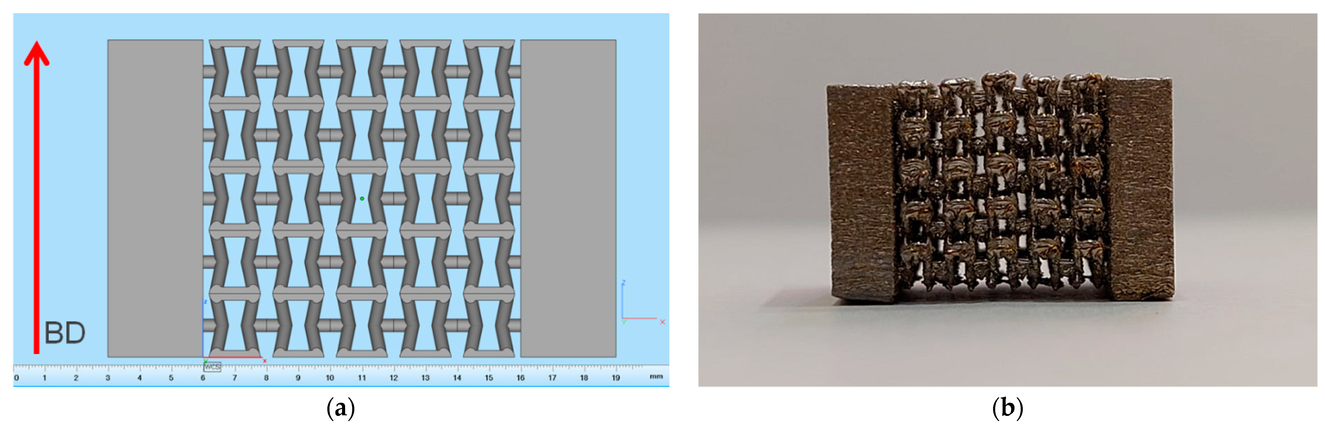
Figure 5.
(a) Orientation of lattice structure based on a single Type 5 cell with bases during fabrication by the SLM technique, with the building direction (BD) indicated; (b) Fabricated lattice structure based on a single Type 5 cell.
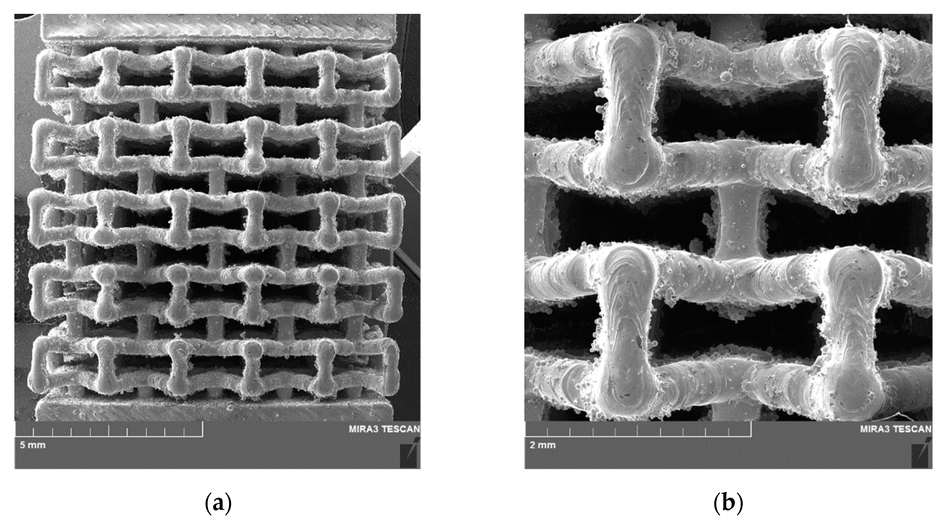
Figure 6.
SEM images of the fabricated lattice structure based on a single Type 5 cell. (a) General view; (b) Highly magnified view of two cells.
Figure 7.
XRD patterns. (a) Initial powder of TiNi alloy; (b) A lattice structure sample fabricated by the SLM technique.
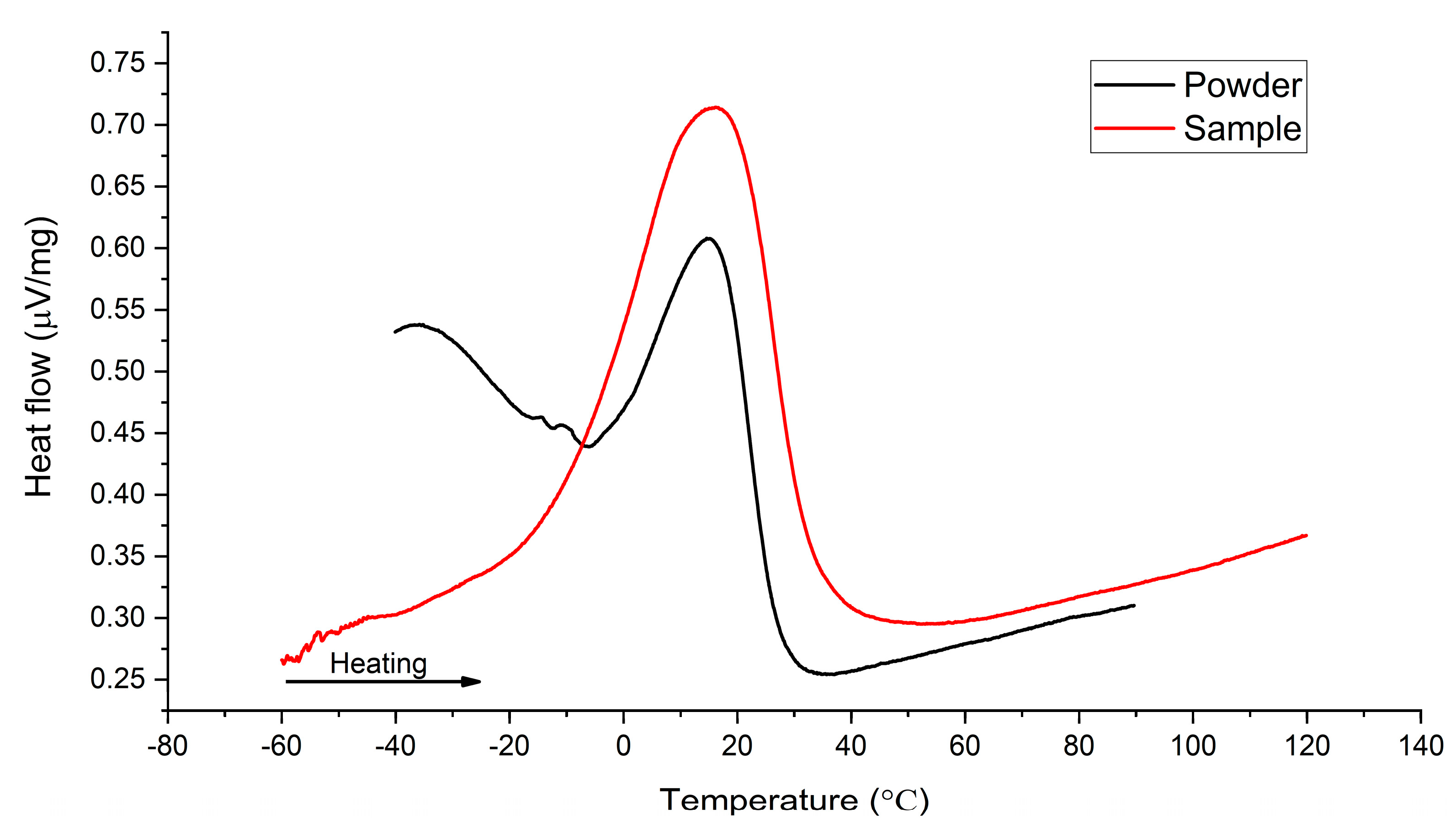
Figure 8.
DSC curves for initial powder and lattice structure sample fabricated by the SLM technique.
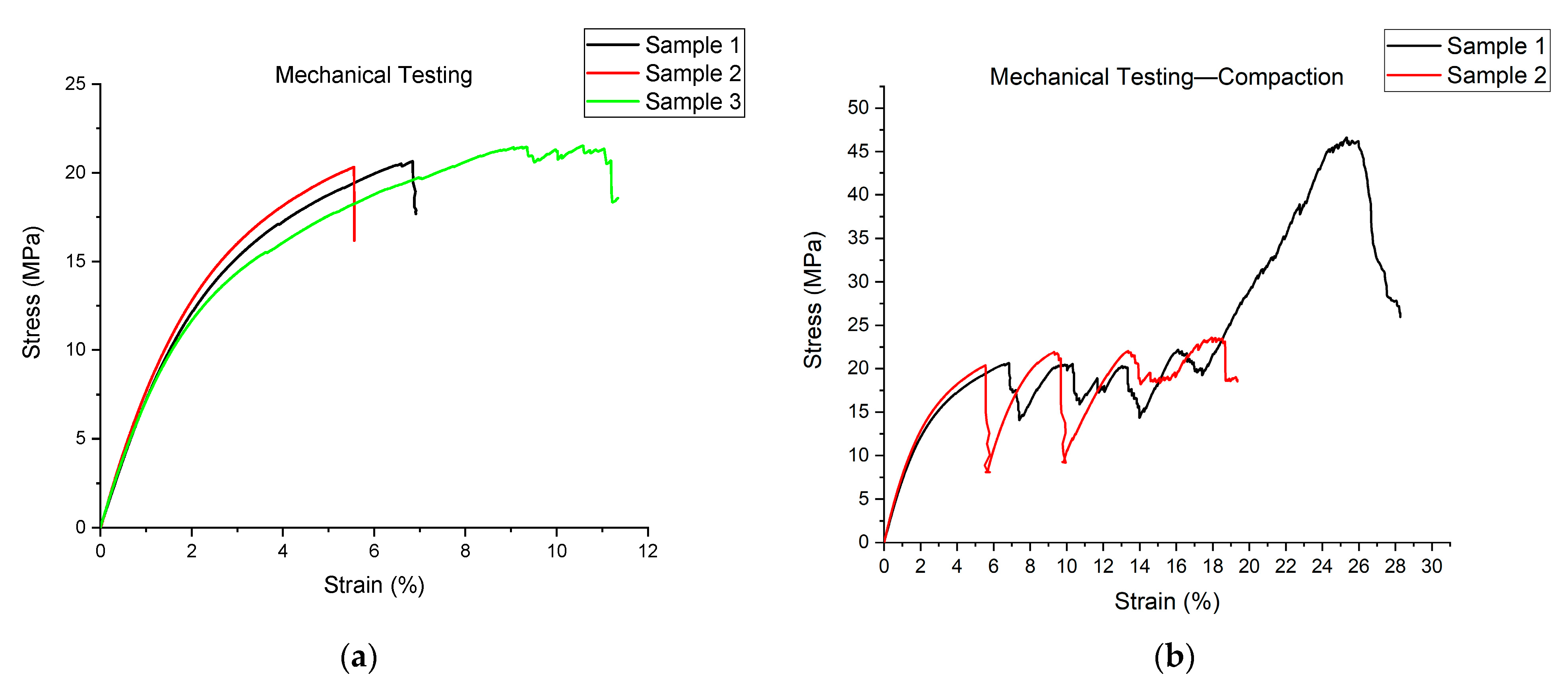
Figure 9.
Mechanical compression test results: (a) Stress–strain curves for three samples plotted before initial failure; (b) Stress–strain curves for two samples plotted during compaction.
Figure 10.
SEM images of sample 2 after compression to failure tests: (a) General view of lattice structure with visible fractures; (b) Partially fractured central cell.
Figure 11.
A variation in length and width of the lattice structure (δl and δb) during compression.
Figure 12.
Sample cycling by compression loading: (a) Cycling with stress rising from 9 to 20 MPa; (b) five cycles under 20 MPa.
Figure 13.
Maximum, reversible, and irreversible strain as a function of cycle.
Table 1.
Transformation temperatures.
| | As, °C | Ap, °C | Af, °C |
|---|
| Powder | −3 | 15 | 28 |
| Sample | −10 | 16 | 34 |
Table 2.
Mechanical properties of lattice structure samples.
| | Elastic
Modulus, GPa | Yield Strength,
MPa | Ultimate Comp.
Stress, MPa | Failure Strain,
% |
|---|
| Sample 1 | 0.796 | 9.55 | 20.97 | 6.84 |
| Sample 2 | 0.838 | 10.14 | 21.57 | 5.55 |
| Sample 3 | 0.820 | 9.4 | 22.48 | 9.33 |
| Average | 0.818 | 9.70 | 21.67 | 7.240 |
| Standard deviation | 0.021 | 0.391 | 0.760 | 1.921 |
Table 3.
Resultant strain achieved during cycling.
| Cycle Number | Stress, MPa | εmax, % | εrev, % | εirr, % |
|---|
| 1 | 9 | 0.999 | 0.993 | 0.006 |
| 2 | 10 | 1.152 | 1.125 | 0.027 |
| 3 | 12 | 1.503 | 1.458 | 0.045 |
| 4 | 14 | 1.935 | 1.878 | 0.057 |
| 5 | 16 | 2.520 | 2.430 | 0.090 |
| 6 | 18 | 3.447 | 3.255 | 0.192 |
| 7 | 20 | 4.671 | 4.395 | 0.276 |
| 8 | 20 | 4.380 | 4.224 | 0.156 |
| 9 | 20 | 4.269 | 4.125 | 0.144 |
| 10 | 20 | 4.167 | 4.071 | 0.096 |
| 11 | 20 | 4.197 | 4.071 | 0.126 |
| Total amount | | | | 1.215 |
| Publisher’s Note: MDPI stays neutral with regard to jurisdictional claims in published maps and institutional affiliations. |
© 2022 by the authors. Licensee MDPI, Basel, Switzerland. This article is an open access article distributed under the terms and conditions of the Creative Commons Attribution (CC BY) license (https://creativecommons.org/licenses/by/4.0/).


