Abstract
The combination of strength of transformation-induced plasticity (TRIP) steel and ductility of twinning-induced plasticity (TWIP) steel can be achieved by manufacturing laminated composites via cold roll bonding (CRB). Work hardening of the surface before CRB produces deformation lenses (DLs), which play significant role in bonding, but are reported rarely in the literature. The present work aimed to study the DLs at the bonding interface of the laminated composite made of high-alloy TRIP and TWIP steels manufactured by CRB. The DLs and interfaces were investigated by means of scanning and transmission electron microscopy, roughness measurement, tensile and peel tests. Laminates showed ultimate tensile strength up to 900 MPa and elongation up to 45% maintaining the layer’s integrity up to failure. The TWIP–TWIP interface has shown higher maximum peel strength (up to 195 N/cm) than that of a TRIP–TWIP interface (up to 130 N/cm), which was found to be in direct proportion to the overall area of DLs. Bonding of the laminate layers was found to occur between DL fragments.
1. Introduction
Continuously increasing material demands for lowering fuel consumption, reducing air pollution while keeping high mechanical properties have stimulated the development of advanced high-strength steels (AHSS) [1]. Already three generations of different AHSS are present, exploring one of the most beneficial microstructural effects of steels (and not only), which are transformation-induced plasticity (TRIP), and twinning-induced plasticity (TWIP). While steels with TWIP effect are remarkably ductile at low work hardening, reaching 100% elongation and beyond [2], TRIP effect significantly increases strain hardening, which allows a steel to have ultimate tensile strength up to 1.5 GPa, while maintaining sufficient plasticity [3]. Both effects are closely related to each other and depend on the stacking fault energy (SFE) and phase stability, which can be controlled by tuning the chemical composition [4,5]. However, the underlying microstructural processes are significantly different. Whereas in TRIP steels a strain-induced martensitic phase transformation from fcc austenite to bcc α’-martensite occurs, in TWIP steels mechanical twinning is the major deformation mechanism.
Further increase in mechanical properties can be achieved by grain refinement via severe plastic deformation (SPD) or by composing different steel grades to combine their strong sides, for instance strength of a TRIP steel with ductility of a TWIP steel. A method, which combines both approaches is accumulative roll bonding (ARB) [6]. ARB is a repetitive cold roll bonding (CRB) process in which two sheets of material are joined together by rolling with a typical thickness reduction of 50% after appropriate surface treatment [7]. Unlike hot rolling, CRB is conducted at temperatures below recrystallization, resulting in a grain refinement.
During hot rolling, an oxide film forms on the surface of metals due to thermally enhanced oxidation and hinders bonding [8]. To remove the oxide film, modern hot roll bonding methods are conducted under a vacuum [9,10]. In contrast, cold roll bonding (CRB) does not require a vacuum but does require work-hardening of the surface by brushing or grinding. The advantage of work-hardening is an earlier onset of adhesion than with unbrushed surfaces. Brushing also has the function of surface cleaning and activation (i.e., increase in surface tension [11]). During roll bonding, the hardened layers break-up and release the uncontaminated material, which is subjected to adhesive bonding [12]. CRB is easier, cheaper and allows successful bonding of various alloys, including interstitial-free steels [13], stainless steels [14] and even alloys of different base metals, such as Fe–Cu, Fe–Ag, Fe–Al [15], Fe–Ti [16], etc.
Work hardening by brushing is inherently non-uniform and produces deformation lenses (DLs), which have been known since the 1950s as heavily worked and hardened fragments of a metal matrix [17]. Since then, papers dedicated to experimental investigation of laminates manufactured by roll bonding have not mentioned DLs even if the work is focused on the microstructure [18], or bonding interfaces [8,19,20]. Thus, there is a lack of experimental investigations on DLs and bonding zones, although the experimental techniques have been drastically improved during the last 60 years.
The authors of the present working group have recently started to fill this research gap by investigating the DLs within a bonding layer of high-alloy TRIP and TWIP steels. The first work by Qiu et al. was dedicated to the first trials of fabrication of the two-layered TRIP–TWIP composites and their mechanical properties [21]. By observing the cross sections, it was revealed that the DLs have laminated structure and cannot be indexed by means of electron back-scattered diffraction (EBSD). The imaging of the steel surfaces via top-down view did not allow location of the DLs directly after brushing. However, the fragmented DLs were revealed on the delaminated surfaces after peel tests.
The second work by Seleznev et al. was dedicated to the fabrication of the four-layered TRIP–TWIP composite and the microstructural evolution of the bonding zone along the fabrication process [22]. By combining EBSD with energy dispersive X-ray (EDX) analysis, it was revealed that a DL indeed consists of heavily deformed steel matrix with a structure of alternating micro-layers of higher and lower oxygen content, but it is not an oxide. However, when exposed to annealing, the excessive oxygen of DL forms oxides of Mn, Si, and Cr, changing the structure of a DL to a cluster of sub-micron globular oxides in the steel matrix. The DLs were found to deform in a brittle manner during a tensile test, however their role in bonding process was still unclear.
Different authors show similar schematics of the CRB process and refer to the same process of the interface layer break-up, but do not specify clearly whether it is an oxide film [16,23], or a hardened layer [14,24]. Thus, it is unclear, which type of material actually undergoes break-up during CRB. Another uncertainty is the absence of experimental data on the real three-dimensional distribution of DLs in the interface. Thus, theoretical and modelling studies are dealing with two-dimensional interpretation of the CRB [12,25].
The aim of the present work is to clarify the above-mentioned uncertainties for CRB of high-alloy steels with TRIP and TWIP effects, which show the most promising results when being used for production of laminated metal composites (LMCs) by ARB [26,27]. In particular, Qiu et al. investigated laminates, produced with CRB using two specific steel grades X5CrMnNi-16-6-6 (TRIP steel) and X5CrMnNi16-6-9 (TWIP steel) [21]. Both bilayer [21] and four-layer [22] composites of TWIP and TRIP steels have demonstrated good bonding, and the remarkable combination of high yield strength (up to 1 GPa) and high ductility (up to 35% elongation). Surprisingly, CRB of a TRIP–TRIP laminate was unsuccessful, although the difference between used TRIP and TWIP steels is only 3 wt.% of Ni, resulting, however, in different stacking fault energies and, consequently, in different microstructural processes. To reveal the reason for such disparity, a thorough investigation of the bonding zone and DLs is needed.
Therefore, the DLs in the bonding interface of LMC made of high-alloy TRIP and TWIP steels by CRB were studied. First of all, the surface microstructure of both steels was investigated not only after CRB, but also before and after brushing. Then, TRIP–TWIP and TWIP–TWIP laminates were fabricated using CRB. Mechanical properties of these laminates were investigated by tensile and peel tests. The microstructure, composition, shape, size, and distribution of DLs within the bonding zones of LMCs were thoroughly examined using scanning and transmission electron microscopy. In addition, the roughness of TRIP and TWIP steel surfaces was measured at each step of manufacturing and after delamination. Joint analysis of all the obtained data allowed revealing of correlations between DLs and CRB of TRIP and TWIP steels.
2. Materials and Methods
2.1. Material Properties
Two high-alloy austenitic stainless steels X5CrMnNi-16-6-6 (TRIP steel) and X5CrMn Ni16-6-9 (TWIP steel)—both provided by ACTech Company, Freiberg, Germany—were used in the present work. As-cast and solution-annealed plates with dimensions of 340 × 340 × 10 mm3 were milled and cut to 50 mm wide sheets. The chemical composition of steel samples is summarized in Table 1, where C and S were analysed via combustion, Mn by energy dispersive X-ray spectroscopy (EDS), N by melt extraction, and other elements by spark emission spectrometry.

Table 1.
Chemical composition of two steel grades, used in the present study (given in wt.%): X5CrMnNi-16-6-6 (TRIP steel) and X5CrMnNi16-6-9 (TWIP steel).
The preparation of material and composite manufacturing is shown in Figure 1. The steel sheets were hot-rolled down to 1.5 mm thickness at 1100 °C, recrystallized and solution annealed at 1050 °C for 20 min followed by quenching with He gas. After this, the sheets were pickled, cleaned, and brushed with a custom-made wire rod brushing machine of 230 mm diameter under 2000 rpm rotational speed, 30 N contact pressure and feed rate of 4 mm/s. Before rolling, the sheets were fixed together by spot welding at one end of the stack. The stacked sheets were clamped, heated up to 450 °C and roll bonded under a load of 1 MN at a speed of 0.4 m/s with a thickness reduction of 50%.
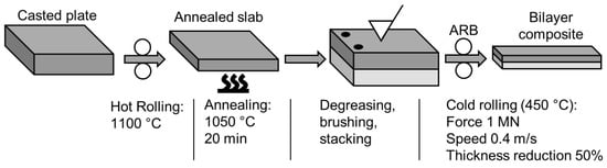
Figure 1.
Schematic representation of the bilayer composite manufacturing.
2.2. Mechanical Testing
Mechanical properties of the manufactured laminates were investigated using quasi-static tensile loading and peel testing. To test the quality of the bonding zone under different directions, miniature tensile specimens (Figure 2a) were cut from the laminate at three different angles to the rolling direction: 0°, 45° and 90° (Figure 2c). In order to estimate the plastic anisotropy of the fabricated laminates, the plastic anisotropy parameter r (also known as the Lankford parameter) was calculated for each above-mentioned angle according to the following equation [28]:
where b and a correspond to the width and thickness of the gauge part of the tensile specimen, respectively. The values before deformation are given on Figure 2a: b0 = 1.8 mm and a0 = 1.5 mm, whereas the values after the deformation (b1, a1) were measured from the fracture surfaces of each specimen. Further, mean anisotropy rm and planar anisotropy rp were calculated according to the DIN EN ISO 10,113 [29]:
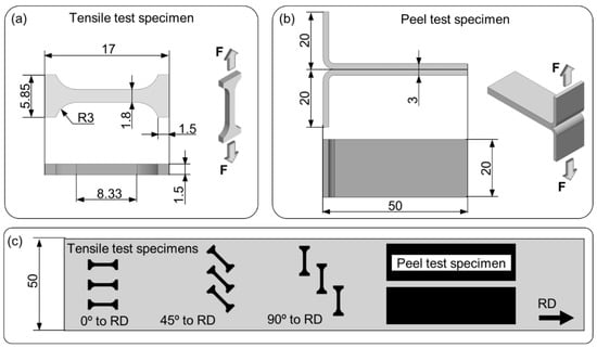
Figure 2.
Geometry of specimens in mm for tensile (a) and T-peel (b) testing and their positions with respect to the rolling direction of the laminate (c).
Quasi-static tensile tests were performed using a miniature screw driven load frame (Kammrath & Weiss GmbH, Schwerte, Germany) at an initial strain rate of 10−3 s−1. Engineering strain was measured in situ by digital image correlation (DIC) of the gauge part of a specimen, grinded with 18 µm grinding paper. After conducting the tensile tests with at least three specimens per orientation, the following mechanical properties were calculated: ultimate tensile strength (UTS), elongation to failure (ETF), and 0.2% offset yield strength (Rp0.2).
The bond strength was studied with the T-peel test according to ASTM-D1876-01 [30], using the T-peel specimen geometry (Figure 2b). Two peel test specimens were cut from each laminate (Figure 2c) and opened manually to form a T-shape. The peel tests were performed using a tensile testing machine under a crosshead velocity of 1 mm/min. In order to evaluate the bond strength two parameters were calculated: maximum peel strength, MPS and work of delamination, A. MPS was calculated according to Chen et al. [24], as the maximum force during peel test divided by the bond width. The work of delamination A was calculated as an integral under the load (F) vs. displacement (l) curve related to the overall surface of the T-peel specimen S:
where lf denotes displacement to failure (full delamination). Despite the fact that such an estimation of the work of delamination is not fully accurate (the change of the local loading direction during delamination is not considered), it is adequate and comparable within the present work.
2.3. Surface Roughness Measurement
Surface roughness parameter Ra was measured using a roughness measuring system with a white light confocal distance sensor (Breitmeier GmbH, Ettlingen, Germany). At least three profiles parallel and perpendicular to the RD were acquired from the surfaces of TRIP and TWIP steels of following conditions:
- Pickled;
- Brushed with blunt bristles;
- Brushed with sharpened bristles;
- Delaminated after the peel test.
Although the CRB was conducted only after brushing with sharpened bristles, the difference of the surface roughness after brushing with blunt bristles is of high interest with respect to the thickness of the work-hardened layer. The length of each roughness profile was set to 50 mm except profiles perpendicular to RD from the peel test specimens, which were only 20 mm wide (Figure 2b).
2.4. Microstructure Investigation
Investigations of the microstructure were conducted by means of a MIRA3 scanning electron microscope (SEM, Tescan, Brno, Czech Republic), including secondary electron (SE) and back-scattered electron (BSE) imaging, and electron back-scattered diffraction (EBSD) mapping combined with energy dispersive X-ray spectroscopy (EDS). These SEM techniques were applied to investigate the microstructures of steel surface cross sections after brushing, fracture surfaces after tensile and peel tests and DLs. In addition, the nanostructure of DLs was investigated with a JEM-2200FS transmission electron microscope (TEM, JEOL, Tokyo, Japan), including selected area electron diffraction (SAED). For this purpose, a thin lamella was extracted from the DL with focused ion beam (FIB) technique.
2.5. Lens Shape and Distribution Statistics
Some statistical insights can be obtained from the cross sections of bonding zones within the laminates, such as DL thickness demonstrated on Figure 3a. However, this information is too scarce, as we observe only a one-dimensional slice of the two-dimensional interface. To overcome this issue, delaminated surfaces after peel tests were used to quantitatively estimate sizes and distribution of DLs within the bonding zones of laminates (Figure 3b). In addition to thickness of DLs tlens, which can be obtained only from a cross section, an analysis of surfaces after delamination allows measuring of all the other parameters, such as length llens, width wlens, and total area Alens of DLs. One of the crucial parameters here is the length of gaps between DLs fragments lgap—these are the areas where non-contaminated material comes to the surface and forms bonding.
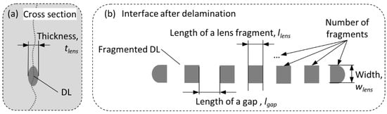
Figure 3.
Schematic description of measured lens parameters from the cross section (a) and from the interface after the delamination test (b).
Two surfaces of TWIP steels from delaminated peel test specimens of TRIP–TWIP and TWIP–TWIP composition, respectively, were taken for this purpose. The analysed areas with the size of 4.3 × 3.2 mm2 were scanned with SEM using BSE imaging and subjected to measurements according to Figure 3b. Statistical data from this analysis shall be used also in a future work for bonding modelling according to the work of Schmidtchen [11].
3. Results
3.1. Surface Preparation before ARB
3.1.1. Pickling
The microstructure of the TRIP and TWIP steels after hot rolling and subsequent heat treatment demonstrate full recrystallisation and no signs of strain hardening (Figure 4) [22]. Due to pickling the surfaces of both steels are scale- and oxide-free. Shallow etching pits are located in the areas where grain boundaries come to the surface. The observed surface profile inhomogeneity is expected to influence the resulting thickness of the strain-hardened layer after brushing.
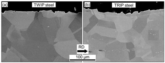
Figure 4.
Surfaces cross section from TWIP (a) and TRIP (b) steels after pickling, obtained from polished sections by SEM (SE detector).
3.1.2. Brushing
As was mentioned in the introduction, the work-hardened layer plays a crucial role in CRB: it breaks down during rolling and releases virgin material, which undergoes adhesive bonding. To study the effect of the bristle’s geometry on the work-hardened layer the TWIP steel was brushed by 0.45 mm diameter bristles with a blunt tip (Figure 5c) and with a sharp tip (Figure 5f). Resulting surface cross sections of TWIP steel were compared to each other (Figure 5a–e) and to the TRIP steel brushed with a sharpened brush (Figure 5g,h).
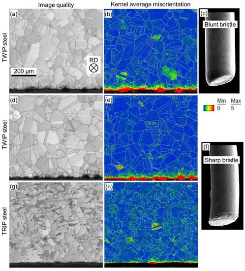
Figure 5.
Comparison of the deformed surface layer thickness of TWIP (a,b,d,e) and TRIP (g,h) steels after brushing of slabs with 0.45 mm diameter brush with blunt (c) and sharp (f) bristles. Cross sections are perpendicular to brushing and rolling direction (RD) as indicated on (a). Image quality (left column, a,d,g) and Kernel average misorientation (right column, b,e,h) were obtained by electron backscatter diffraction mapping.
The influence of the brush tip geometry on the brushed surfaces of TWIP and TRIP steels was investigated using EBSD mapping and subsequent application of the Kernel average misorientation mapping with a maximum misorientation angle up to 5° between eight nearest neighbours of each measuring point (Figure 5, right column). Bristle tips of a worn-out (used) brush are round, which leads to the formation of the uneven work-hardened layer with the depth up to 50 µm after brushing (Figure 5a,b). Here, deformation lenses stick out from the surface, increasing the overall roughness of the TWIP steel. Brushing of TWIP steel with a sharpened brush provides a thicker and uniform work-hardened layer (up to 70 µm, Figure 5d,e). In this case lenses are embedded into the surface, making it smoother. Thus, a sharpened brush provides a thicker, smoother, and more uniform hardened layer.
The depth of the work-hardened layer of the TRIP steel layer was found to be only up to 20 µm (Figure 5g,h). In contrast to softer TWIP steel, the surface of TRIP steel undergoes much higher strain hardening by brushing and protects deeper layers from deformation. This leads to a poor CRB ability of mono-material TRIP steel laminate and explains failure of the TRIP–TRIP bonding. In contrast, the TWIP steel ensures good bonding between the layers. Thus, the manufacturing of a laminated composite by ARB using selected alloys was successful in case of TWIP–TRIP and TWIP–TWIP combinations, which were further investigated.
3.2. Mechanical Properties
3.2.1. Quasi-Static Tensile Loading
For the sake of clarity, only one representative curve was plotted on the stress–strain diagram for each type of orientation between loading axis and RD (Figure 6a). The resulting tensile properties show some anisotropy depending on the orientation of a tensile specimen to the rolling direction. Both TRIP–TWIP and TWIP–TWIP laminates demonstrate very good ductility with the elongation to failure (ETF) of about 40% and 42% on average, respectively. Ultimate tensile stress (UTS) of the TWIP–TWIP laminate reaches up to 800 MPa, whereas in case of the TRIP–TWIP the UTS reaches up to 900 MPa due to the strain hardening via TRIP effect. For the same reason, the 0.2% offset yield strength is also higher for the TRIP–TWIP composite (750 MPa on average) than that for the TWIP–TWIP composite (650 MPa on average).
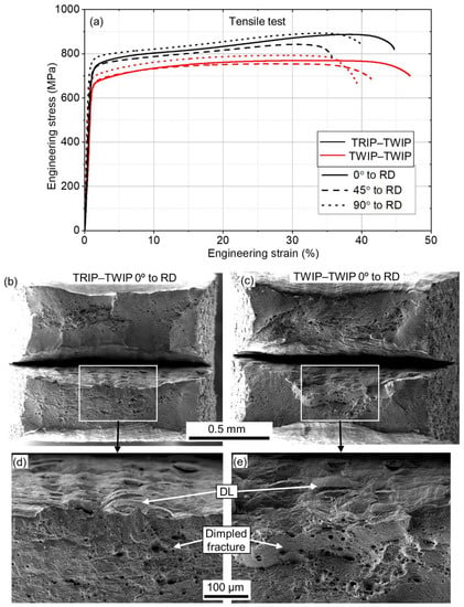
Figure 6.
Results of the mechanical testing of TRIP–TWIP and TWIP–TWIP bilayer laminates after quasi-static tensile loading at different angles to rolling direction (a). SEM images show fracture surfaces after the tensile test of TRIP–TWIP (b) and TWIP–TWIP (c) specimens and their magnified views on (d) and (e), respectively.
In general, the laminates show higher plasticity along the RD and higher strength perpendicular to RD. Regardless of the loading axis orientation, delamination occurs only during the final rupture of layers and only in the area of necking (Figure 6b,c), which indicates good bonding. The DLs embedded to the delaminated bonding zone can be clearly seen on the magnified views (Figure 6d,e). Both TRIP–TWIP and TWIP–TWIP laminates show 100% dimpled fracture surface, which indicates fully ductile fracture.
The results of the anisotropy calculations are presented in Table 2. All the obtained r values are smaller than one, indicating a behaviour in which the material deforms more in thickness than in width. This leads to the local reduction in sheet thickness under tensile stress, resulting in a failure by necking. Both laminates show maximum plastic anisotropy at 45° (r45), and small negative values of plain anisotropy rp as a consequence, which is typical for austenitic stainless steels [31]. The rm values of the investigated TRIP–TWIP laminates are relatively low (0.63–0.72) in comparison to the deep drawable and IF steels (1.7–1.9) [32]. The plasticity is significantly influenced by the crystallographic texture of the steel: the higher the volume fraction of {111} planes in the RD, the higher the plasticity. Despite the fact that the microstructure of TRIP–TWIP laminates is not significantly texturized directly after rolling, the volume fraction of {111} planes increases drastically during the tensile deformation via intensive twinning [22]. This explains high ductility of TWIP steels despite low rm values. According to lower anisotropic parameters of TWIP–TWIP laminate, a TWIP steel layer thins out more than a TRIP steel layer, which explains the better plating behaviour of TWIP steel.
Table 2.
Anisotropic parameters, calculated after the tensile tests of TRIP–TWIP and TWIP–TWIP laminates, including plastic anisotropy r for each of the angle between the rolling direction and the tensile loading axis, mean anisotropy rm and planar anisotropy rp.
3.2.2. Delamination Test
The results of peel tests of two specimens from both TRIP–TWIP and TWIP–TWIP composites are summarized on Figure 7a. Due to the inherent instability of a delaminating crack propagation, the loading curves are heavily serrated and show significant fluctuations. On average, the maximum peel strength (MPS) equals to 108 N/cm for TRIP–TWIP and 184 N/cm for the TWIP–TWIP laminate, which is close to the MPS obtained by Qiu et al. (225–138 N/cm) [21]. The average work of delamination A is 21 mJ/cm2 for TRIP–TWIP and 43 mJ/cm2 for the TWIP–TWIP laminate, which is twice as much. Calculation of the work of delamination for the peel test results obtained by Qiu et al. give much smaller values: 15 mJ/cm2 for TRIP–TWIP and 22 mJ/cm2 for the TWIP–TWIP laminate, which indicates a significant improvement of the bond strength, achieved in the present work.
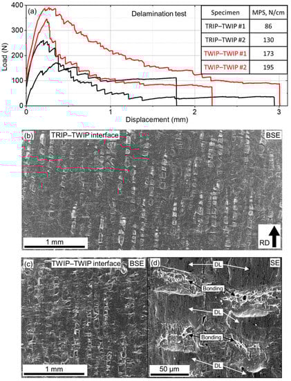
Figure 7.
Results of the delamination testing of TRIP–TWIP and TWIP–TWIP bilayer laminates: load vs. displacement curves (a), and SEM images in BSE contrast with delaminated interfaces of TRIP–TWIP (b) and TWIP–TWIP (c) steels after delamination. The inset on (a) shows values of maximum peel strength (MPS) for each specimen. Magnified view of the TWIP–TWIP surface (SE contrast) indicates fragmented deformation lenses (“DL”) and bonding zones (“Bonding”) with white and black arrows, respectively (d).
Considering higher mechanical properties of the TRIP–TWIP laminate (Figure 6a) and integrity of a specimen up to the failure (Figure 6b), it can be concluded that the work of delamination of 21 mJ/cm2 corresponds to sufficiently good bonding. To achieve better comparison between peel test results, a method based on elementary plasticity shall be developed in a future work.
The surfaces of T-peel tests after delamination look different: the amount of the surface area covered by DLs is noticeably higher in case of TWIP–TWIP laminate (Figure 7c), than in case of TRIP–TWIP laminate (Figure 7b). This observation correlates with the difference of loading curves and resulting work of delamination. As can be seen on the magnified image of the TWIP–TWIP delaminated surface (Figure 7d), DLs have undergone fragmentation. Gaps between DL fragments consist of a dimpled fracture surface, which indicates full interface bonding between the layers and ductile fracture during the peel test. Thus, the resulting bond strength depends on the overall area of gaps between DLs, and, consequently, on the total amount of interface area covered by DLs. In order to verify this assumption, the quantitative analysis of DLs was conducted in Section 3.3.3 using the delaminated surfaces of specimens after peel test, which showed the highest MPS (specimens TRIP–TWIP #2 and TWIP–TWIP #2)
3.2.3. Surface Roughness
The roughness measurements of surfaces of TRIP and TWIP steels after pickling brushing and delamination are summarized on Figure 8. Despite the same treatment, the roughness parameter Ra of pickled TRIP and TWIP steels differs significantly: 4 and 2.6 µm, respectively. This difference is reduced after brushing. Brushing with blunted bristles result in Ra of 3.1 µm for TWIP steel and 2.8 µm for TWIP steel. Here, the roughness of TWIP steel increases with respect to the non-brushed state, which indicates that the material is rather unevenly smeared. Brushing with sharp bristles results in Ra of 2.3 µm for TWIP steel and 2.6 µm for TRIP steel, which indicates higher rate of smoothening for both steels. This result correlates with the position of DLs, which are embedded deeper in the surface of TWIP steel in case of brushing with sharp bristles (compare Figure 5b,e).
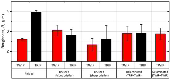
Figure 8.
Column plot of the linear roughness Ra of TRIP (black bars) and TWIP (red bars) steel surfaces after etching, brushing with blunt and sharp bristles and after delamination tests of roll bonded laminates, brushed with sharp bristles.
After the peel tests, both delaminated surfaces of TRIP and TWIP steels show higher roughness than that before CRB. Moreover, the initial difference of Ra value is almost levelled out, resulting in 2.9 µm for both steels in both TRIP–TWIP and TWIP–TWIP laminates. This effect can be explained by mutual smoothing and penetration of asperities of TRIP and TWIP steels during CRB.
3.3. Deformation Lenses Properties
3.3.1. Scanning Electron Microscopy Investigation
An example of a typical DL after ARB of TRIP–TWIP laminate is shown in Figure 9. A DL can be effectively revealed using BSE detection and appears as a dark region elongated along the bonding zone (Figure 9a). The matrix, which surrounds a DL, is fully austenitic within the TWIP steel (Figure 9b) and contains a few percent of α’ martensite within the TRIP steel (Figure 9c). The bright stripes within the DL consist of deformation-induced α’ martensite with the average grain size of 0.3 µm. Although there is an excessive amount of oxygen within a DL (Figure 9i), a DL is not an oxide, but a steel matrix after severe plastic deformation (SPD) with laminated structure of alternating Fe-rich (Figure 9d), and Ni-Mn-Cr-rich layers (Figure 9e–g). The amount of Mn in a DL is reduced with respect to the surrounding matrix.
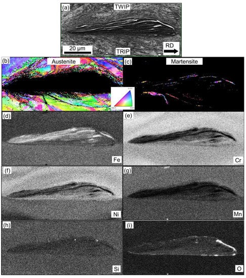
Figure 9.
Example of a deformation lens in a bonding zone between TRIP and TWIP steels cross-sectioned parallel to the RD: BSE image (a), orientation maps of austenite (b) and α’ martensite (c), distribution maps of the main chemical elements (d–h) as well as oxygen (i).
3.3.2. Transmission Electron Microscopy Investigation
The fine structure of a DL and the surrounding material was investigated by means of TEM. A DL within the bonding zone of a TWIP–TWIP laminate was subjected to FIB on one of its sides, so that all characteristic areas (steel matrix, oxide, DL) would fit into a 7 µm width linear segment (Figure 10a). Before sectioning the surface of selected area was covered with Pd layer in order to protect the investigated material from the possible damage from FIB (Figure 10b). The region in extracted lamella (Figure 10c) was investigated by means of scanning transmission electron microscopy (STEM) and represents all three areas: DL on the left, an oxide layer in the middle, and a steel matrix on the right of Figure 10d.
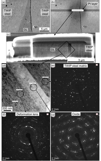
Figure 10.
Investigation of a DL and surrounding area within a TWIP–TWIP bonding zone by means of TEM: selected area on the cross section (a), segment subjected to the FIB protected by Pd layer (b), extracted lamella (c), magnified view of the lamella (d), where circles indicate regions of selected area electron diffraction of the steel matrix (e), DL (f), and oxide (g).
The austenitic steel matrix has ultrafine-grained (UFG) microstructure, demonstrating plenty of reflexes, which yet remain point-wise (Figure 10e). Within an area near DL, single grains can be still distinguished and indexed by means of EBSD (Figure 9b). In contrast, the area within a DL is non-indexed with EBSD technique due to even higher plastic deformation. Reflexes on the selected area electron diffraction (SAED) from the DL are smeared along the radiuses (Figure 10f), indicating that the crystal lattice of nano-sized grains is heavily distorted.
The oxide layer is located between the steel matrix and DL and can be seen as the dark stripe on SE image (Figure 10a) and as the bright stripe on the STEM image (Figure 10d). Multiple observations indicate that an oxide layer can be located either on one side of a DL, or a DL is free from this layer. The oxide layer can cover only a small part of a DL, as well (Figure 9i). Important is that the remaining bonding zone is usually free from oxides [22]. The boundary between the oxide layer and the steel matrix is sharp, whereas the boundary between the oxide layer and DL is smooth (Figure 10d). This means that the 400 nm thick oxide layer was formed on the surface of a DL during brushing and was later bonded with the steel matrix during CRB. Suitable models for surface brushing shall be used to investigate this statement in future work [33].
3.3.3. Distribution Statistics of Deformation Lenses
Thorough investigation of cross sections and surfaces of the bonding zones after a peel test (Figure 7b,c) allowed development of statistical insight on the sizes and distribution of DLs (Figure 11). A DL is formed during brushing and has a lenticular-shaped cross section. Depending on the interface type, the average DL dimensions (llens × wlens × tlens) are 339 × 62 × 17 µm3 for the TRIP–TWIP interface, and 434 × 71 × 12 µm3 for the TWIP–TWIP interface (Figure 11c,e,g). During CRB with 50% thickness reduction, DLs break up into 5–6 fragments (Figure 11f) with the average length of a fragment lfrag = 66–79 µm (Figure 11a). Gaps between the fragments of DLs lgap are 41–44 µm long (Figure 11b) and have a total length of 171 and 201 µm (Figure 11d) within each DL in TRIP–TWIP and TWIP–TWIP interface, respectively.
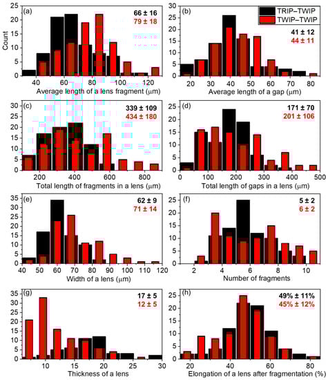
Figure 11.
Distribution of geometrical parameters in absolute numbers (counts), measured manually from TRIP–TWIP (black bars) and TWIP–TWIP (red bars) interfaces after delamination. Numbers in the upper right corner of each diagram correspond to the average values and standard deviation. (a) Average length of a lens fragment, (b) average length of a gap, (c) total length of fragments in a lens, (d) total length of gaps in a lens, (e) width of a lens, (f) number of fragments, (g) thickness of a lens, (h) elongation of a lens after fragmentation.
The total length of gaps with respect to the total length of DLs fragments gives an average value of DLs elongation of 45–49% (Figure 11h), which is in a good correlation with the overall thickness reduction of 50% during CRB. The calculated value of a DLs elongation does not correspond to the plastic deformation of DLs, which deform in a brittle manner, but to the overall increment in DLs and gaps length with respect to the initial length of DLs before CRB.
4. Discussion
After receiving and analysing the data from delaminated surfaces of the peel test specimens, the correlation of DLs and bond strength can be estimated. By relating the size of the analysed area of each delaminated surface (4.3 × 3.2 mm2) to the overall areas covered by DLs, one can calculate the relative area of DLs after CRB (Table 3, 2nd column). The latter would be 12% for the TRIP–TWIP and 20% for the TWIP–TWIP interfaces. Assuming that the elongation of the whole interface during CRB equals to the elongation of DLs, which are embedded in it, the size of the analysed area before CRB can be estimated as the final one (4.3 × 3.2 mm2) multiplied by 0.49 in case of TRIP–TWIP and 0.45 in case of TWIP–TWIP laminate (Figure 11h). According to [22], the DLs do not show any signs of plastic deformation. Thus, the relative area of DLs before CRB can be calculated as the relation of total area of DLs segments to the analysed area before CRB: 19% for the TRIP–TWIP and 29% for the TWIP–TWIP interfaces (Table 3, 1st column). Finally, the relation of the total area of gaps between DLs to the analysed area gives the relative area of fully bonded regions, which is 6% for the TRIP–TWIP and 9% for the TWIP–TWIP interfaces (Table 3, 3rd column).
Table 3.
Summarizing analysis of the results obtained from peel tests of TRIP–TWIP and TWIP–TWIP laminates.
The MPS values for the analysed peel test specimens were calculated in Section 3.2.2 (Figure 7a), and equal to 130 N/cm for the TRIP–TWIP and 195 N/cm for the TWIP–TWIP laminate (Table 3, 4th column). Now, to compare the described parameters with each other, the values of the first row can be divided by the values of the second row, giving the TRIP–TWIP to TWIP–TWIP ratio. The value of this ratio differs slightly among all the parameters within the range of 0.60–0.67. However, most importantly, the ratio of calculated area of full bonding coincides perfectly with the ratio of maximum peel strength values. This finding proves the assumption that the bond strength of an interface between high-alloy CrMnNi steels is in direct proportion to the overall area of DLs and fully bonded regions, which appear in the gaps between DLs fragments after break up during rolling.
Concerning the measured tensile properties, such as ultimate tensile strength and elongation to failure, these properties were found to be affected by the bond strength only when the bond strength is too weak, i.e., delamination occurs before the necking, as shown by Seleznev et al. [22]. The tensile tests in present work did not reveal any significant influence of the bond strength (and DLs) on the tensile properties. Thus, we can conclude that the DLs covering 12–20% of the area after rolling is still enough to maintain structural integrity during mechanical loading.
5. Conclusions
The DLs at the bonding interface of LMC made of high-alloy TRIP and TWIP steels by CRB were studied in present work by means of SEM, TEM, roughness measurement, tensile and peel tests. According to the obtained results and analysed data following conclusions can be drawn:
- Brushing of the TWIP steel with sharp bristles gives a thicker and more uniform work-hardened layer (70 µm) with DLs embedded in the surface. In contrary, brushing with blunt bristles gives a thinner work-hardened layer (50 µm), where DLs stick out from the surface. TRIP steel after brushing has a very thin work-hardened layer (20 µm), which is assumed to be the reason for unsuccessful TRIP–TRIP bonding during CRB.
- Both TRIP–TWIP and TWIP–TWIP laminates demonstrate good mechanical properties with UTS up to 900 MPa and elongation up to 45% with the layer’s integrity persisting up to the tensile fracture.
- The TWIP–TWIP interface shows higher maximum peel strength (up to 195 N/cm) than that of a TRIP–TWIP interface (up to 130 N/cm). Regions of full bonding bet-ween laminate layers were found to be located in gaps between the fragments of DLs.
- The bond strength of an interface between high-alloy CrMnNi steels is in direct proportion to the overall area of DLs and fully bonded regions, which appear in the gaps between DLs fragments after breaking up during rolling.
The abovementioned findings will be used in further investigations in the field of cold roll bonding, in particular accumulative roll bonding of high-alloy steels, including TRIP and TWIP steels.
Author Contributions
M.S. (Mikhail Seleznev)—investigation, formal analysis, methodology, visualization, software, writing—original draft and preparation, writing—review and editing; C.R.—resources; investigation. M.S. (Matthias Schmidtchen)—conceptualization; U.P.—supervision; H.B.—supervision; A.W.—project administration; funding acquisition; writing—review and editing. All authors have read and agreed to the published version of the manuscript.
Funding
This research was funded by German Research Foundation (Deutsche Forschungsgemeinschaft DFG), grant number 448954974.
Informed Consent Statement
Not applicable.
Data Availability Statement
Not applicable.
Acknowledgments
The authors would like to thank colleagues from Technical University of Freiberg, namely Astrid Leuteritz for the extraction of lamella by FIB, Mykhaylo Motylenko for the transmission electron microscopy investigation, Annette Ludwig for the roughness measurements, Heiko Winderlich for conducting the peel tests, Diane Hübgen for the preparation of the cross sections.
Conflicts of Interest
The authors declare no conflict of interest. The funders had no role in the design of the study; in the collection, analyses, or interpretation of data; in the writing of the manuscript, or in the decision to publish the results.
References
- Lesch, C.; Kwiaton, N.; Klose, F.B. Advanced High Strength Steels (AHSS) for Automotive Applications−Tailored Properties by Smart Microstructural Adjustments. Steel Res. Int. 2017, 88, 1700210. [Google Scholar] [CrossRef]
- De Cooman, B.C.; Estrin, Y.; Kim, S.K. Twinning-induced plasticity (TWIP) steels. Acta Mater. 2018, 142, 283–362. [Google Scholar] [CrossRef]
- Soleimani, M.; Kalhor, A.; Mirzadeh, H. Transformation-induced plasticity (TRIP) in advanced steels: A review. Mater. Sci. Eng. A 2020, 795, 140023. [Google Scholar] [CrossRef]
- Frommeyer, G.; Brüx, U.; Neumann, P. Supra-ductile and high-strength manganese-TRIP/TWIP steels for high energy absorption purposes. ISIJ Int. 2003, 43, 438–446. [Google Scholar] [CrossRef] [Green Version]
- Krüger, L.; Wolf, S.; Martin, S.; Martin, U.; Jahn, A.; Weiß, A.; Scheller, P.R. Strain rate dependent flow stress and energy absorption behaviour of cast CrMnNi TRIP/TWIP steels. Steel Res. Int. 2011, 82, 1087–1093. [Google Scholar] [CrossRef]
- Tsuji, N.; Saito, Y.; Lee, S.H.; Minamino, Y. ARB (accumulative roll-bonding) and other new techniques to produce bulk ultrafine grained materials. Adv. Eng. Mater. 2003, 5, 338–344. [Google Scholar] [CrossRef]
- Saito, Y.; Utsunomiya, H.; Tsuji, N.; Sakai, T. Novel ultra-high straining process for bulk materials development of the accumulative roll-bonding (ARB) process. Acta Mater. 1999, 47, 579–583. [Google Scholar] [CrossRef]
- Liu, B.X.; Wang, S.; Chen, C.X.; Fang, W.; Feng, J.H.; Zhang, X.; Yin, F.X. Interface characteristics and fracture behavior of hot rolled stainless steel clad plates with different vacuum degrees. Appl. Surf. Sci. 2019, 463, 121–131. [Google Scholar] [CrossRef]
- Zhao, G.; Li, Y.; Li, J.; Huang, Q.; Ma, L. Experimental analysis of two-layered dissimilar metals by roll bonding. Mater. Res. Express 2018, 5, 026517. [Google Scholar] [CrossRef]
- Li, Y.W.; Wang, Z.J.; Fu, D.G.; Li, G.; Liu, H.T.; Zhang, X.M. Fabrication of high borated austenitic stainless steel thick plates with enhanced ductility and toughness using a hot-roll-bonding method. Mater. Sci. Eng. A 2021, 799, 140212. [Google Scholar] [CrossRef]
- Schmidtchen, M. Mehrskalige Modellierung des Walzplattierens und Walzens von Werkstoffverbunden; Technische Universität Bergakademie Freiberg: Freiberg, Germany, 2017. [Google Scholar]
- Wright, K.P.; Snow, A.D.; Tay, K.C. Interfacial conditions and bond strength in cold pressure welding by rolling. Met. Technol. 1978, 5, 24–31. [Google Scholar] [CrossRef]
- Lin, X.; Koyama, M.; Gao, S.; Tsuji, N.; Tsuzaki, K.; Noguchi, H. Resistance to mechanically small fatigue crack growth in ultrafine grained interstitial-free steel fabricated by accumulative roll-bonding. Int. J. Fatigue 2019, 118, 117–125. [Google Scholar] [CrossRef]
- Li, L.; Nagai, K.; Yin, F. Progress in cold roll bonding of metals. Sci. Technol. Adv. Mater. 2008, 9, 023001. [Google Scholar] [CrossRef] [PubMed]
- McCabe, R.J.; Nizolek, T.J.; Li, N.; Zhang, Y.; Coughlin, D.R.; Miller, C.; Carpenter, J.S. Evolution of microstructures and properties leading to layer instabilities during accumulative roll bonding of Fe-Cu, Fe-Ag, and Fe-Al. Mater. Des. 2021, 212, 110204. [Google Scholar] [CrossRef]
- Li, B.; He, W.; Chen, Z.; Huang, H.; Peng, L.; Li, J.; Liu, Q. Evolution of interface and collaborative deformation between Ti and steel during hot roll bonding. Mater. Charact. 2020, 164, 110354. [Google Scholar] [CrossRef]
- Vaidyanath, L.R.; Nicholas, M.G.; Milner, D.R. Pressure Welding by Rolling. Br. Weld. J. 1959, 6, 13–28. [Google Scholar]
- Howeyze, M.; Eivani, A.R.; Ghosh, M.; Jafarian, H.R. Effects of annealing temperature on microstructure and mechanical behavior of conventionally and severely deformed Fe–24Ni steel by accumulative roll bonding. J. Mater. Res. Technol. 2021, 14, 2428–2440. [Google Scholar] [CrossRef]
- Nambu, S.; Michiuchi, M.; Inoue, J.; Koseki, T. Effect of interfacial bonding strength on tensile ductility of multilayered steel composites. Compos. Sci. Technol. 2009, 69, 1936–1941. [Google Scholar] [CrossRef]
- Kim, M.S.; Park, K.S.; Kim, D.I.; Suh, J.Y.; Shim, J.H.; Hong, K.T.; Choi, S.H. Heterogeneities in the microstructure and mechanical properties of high-Cr martensitic stainless steel produced by repetitive hot roll bonding. Mater. Sci. Eng. A 2021, 801, 140416. [Google Scholar] [CrossRef]
- Qiu, Y.; Kaden, N.; Schmidtchen, M.; Prahl, U.; Biermann, H.; Weidner, A. Laminated TRIP/TWIP Steel Composites Produced by Roll Bonding. Metals 2019, 9, 195. [Google Scholar] [CrossRef] [Green Version]
- Seleznev, M.; Kaden, N.; Renzing, C.; Schmidtchen, M.; Prahl, U.; Biermann, H.; Weidner, A. Microstructural evolution of the bonding zone in TRIP-TWIP laminate produced by accumulative roll bonding. Mater. Sci. Eng. A 2022, 840, 142866. [Google Scholar] [CrossRef]
- Zhang, B.Y.; Liu, B.X.; He, J.N.; Fang, W.; Zhang, F.Y.; Zhang, X.; Chen, C.X.; Yin, F.X. Microstructure and mechanical properties of SUS304/Q235 multilayer steels fabricated by roll bonding and annealing. Mater. Sci. Eng. A 2019, 740–741, 92–107. [Google Scholar] [CrossRef]
- Chen, C.Y.; Chen, H.L.; Hwang, W.S. Influence of interfacial structure development on the fracture mechanism and bond strength of aluminum/copper bimetal plate. Mater. Trans. 2006, 47, 1232–1239. [Google Scholar] [CrossRef] [Green Version]
- Schmidtchen, M.; Kawalla, R. Fast Numerical Simulation of Symmetric Flat Rolling Processes for Inhomogeneous Materials Using a Layer Model−Part I: Basic Theory. Steel Res. Int. 2016, 87, 1065–1081. [Google Scholar] [CrossRef]
- Bouaziz, O.; Masse, J.P.; Petitgand, G.; Huang, M.X. A Novel Strong and Ductile TWIP/Martensite Steel Composite. Adv. Eng. Mater. 2016, 18, 56–59. [Google Scholar] [CrossRef]
- Jafarian, H. Characteristics of nano/ultrafine-grained austenitic TRIP steel fabricated by accumulative roll bonding and subsequent annealing. Mater. Charact. 2016, 114, 88–96. [Google Scholar] [CrossRef]
- Bleck, W. Werkstoffprüfung in Studium und Praxis; Wissenschaftsverlag: Aachen, Germany, 1999; ISBN 3-89653-563-3. [Google Scholar]
- DIN EN ISO 10113; Metallic Materials–Sheet and Strip–Determination of Plastic Strain Ratio. Deutsches Institut für Normung: Berlin, Germany, 2021.
- ASTM D1876-01; Standard Test Method for Peel Resistance of Adhesives (T-Peel Test). ASTM International: West Conshohocken, PA, USA, 2010.
- Siegert, K. Blechumformung; Springer: Berlin/Heidelberg, Germany, 2015; ISBN 9783540684183. [Google Scholar]
- Ghosh, P.; Ray, R.K. Deep drawable steels. In Automotive Steels; Elsevier: Amsterdam, The Netherlands, 2017; pp. 113–143. ISBN 9780081006535. [Google Scholar]
- Black, A.J.; Kopalinsky, E.M.; Oxley, P.L.B. Asperity Deformation Models for Explaining the Mechanisms Involved in Metallic Sliding Friction and Wear—A Review. Proc. Inst. Mech. Eng. Part C J. Mech. Eng. Sci. 1993, 207, 335–353. [Google Scholar] [CrossRef]
Publisher’s Note: MDPI stays neutral with regard to jurisdictional claims in published maps and institutional affiliations. |
© 2022 by the authors. Licensee MDPI, Basel, Switzerland. This article is an open access article distributed under the terms and conditions of the Creative Commons Attribution (CC BY) license (https://creativecommons.org/licenses/by/4.0/).