Article

Tailoring the Austenite Fraction of a Cu and Ni Containing Medium-Mn Steel via Warm Rolling

1
Steel Institute, RWTH Aachen University, 52072 Aachen, Germany
2
Department of Metallurgical and Materials Engineering, Suez University, Suez 43528, Egypt
3
Central Facility for Electron Microscopy, RWTH Aachen University, 52074 Aachen, Germany
*
Author to whom correspondence should be addressed.
Metals 2021, 11(12), 1888; https://doi.org/10.3390/met11121888
Submission received: 28 October 2021 / Revised: 16 November 2021 / Accepted: 19 November 2021 / Published: 23 November 2021
(This article belongs to the Special Issue Microstructures and Mechanical Properties of TRIP/TWIP Steels)

Abstract

:
Developing medium-Mn steels (MMnS) demands a better understanding of the microstructure evolution during thermo-mechanical treatments (TMTs). This study demonstrates the relationship among processing, microstructure, and mechanical properties of a warm-rolled medium-Mn steel (MMnS) containing 1.5 wt. % Cu and 1.5 wt. % Ni. After short-time warm rolling (WR) in an intercritical temperature range, a significant quantity (40.6 vol.%) of austenite was reverted and retained after air cooling. The microstructure and tensile properties of the WR specimens were compared with two typical process routes, namely hot rolling+ cold rolling+ annealing+ tempering (CRAT) and warm rolling+ annealing+ tempering (WRAT). The WR specimen exhibited comparable tensile properties with the CRAT specimens (967 MPa yield strength, 1155 MPa tensile strength, 23% total elongation), with a remarkably shortened process route, which was derived from the dislocation accumulation and austenite reversion during rolling. The WR route stands out among the traditional CRAT and the extended WRAT routes for its excellent tensile properties and compact processing route.

1. Introduction

Medium-Mn steels (MMnS) with 3–12 wt. % Mn content have been identified as prime candidates for third generation advanced high-strength steels, because of their superior combination of strength and ductility [1]. These steels exhibit a fully α’-martensite microstructure in the hot-rolled and cold-rolled states [2,3]. Their excellent mechanical properties emerge when austenite-reverted transformation (ART) annealing [4] in the intercritical temperature range is applied to tailor their ultrafine-grained (UFG) duplex microstructure, which consists of tempered martensite and retained austenite (RA). For MMnS with a higher carbon content [5], the hard martensite phase is transformed after the severe deformation of the steel plate during cold rolling. To improve the rollability, intermediate ART annealing [6] was applied between the cold rolling passes. For MMnS with microalloying element addition and when the precipitation strengthening was targeted, a subsequent ageing or tempering step was also included in the processing route. As a result, for the conventional production of MMnS through hot rolling and cold rolling [7,8], single or multiple post-processing steps were required to adjust the microstructure of MMnS and derive improved mechanical properties.
As an alternative route, warm rolling has been performed, within a deliberately lower temperature range than conventional hot rolling, reducing surface oxidization and improving the plate flatness. The main effect of warm rolling is the refinement of the microstructure, which has been explained by some researchers. Kozasu [9] mentioned two mechanisms that lead to ferrite grain refinement: (1) the recrystallization of austenite grains produced by rolling at intermediate temperatures, and (2) the deformation of austenite grains below the recrystallization temperature. In this way, a large number of defects are introduced into austenite grains as ferrite nucleation sites, resulting in a refined microstructure. It has also been reported by Tamura [10] that in warm-rolled steels, ferrite nucleation takes place not only at austenite grain boundaries, but also in the grain interior, and more nucleation sites lead to a refined grain structure compared to that of conventionally hot-rolled steels.
It is interesting to point out that for MMnS, warm rolling is accompanied not only by dynamic recrystallization, but also by elemental partitioning between deformed martensite and RA. Such phenomena have been reported by Magalhães et al. [11] on MMnS with the composition of Fe-0.086C-8Mn-0.14Si (wt. %). On the one hand, the texture analysis showed that the austenite block observed in the microstructure serves as evidence of austenite recrystallization or diffusional transformation during warm rolling; on the other hand, the enrichment of C and Mn in austenite was also demonstrated by measurements using energy dispersive spectroscopy (EDS) and scanning electron microscopy (SEM), indicating the preferential dynamic partitioning of C and Mn to austenite during warm rolling.
The microstructure produced by warm rolling can result in the desired mechanical properties in MMnS. In the analysis of MMnS by Magalhães et al. [12], a Fe-0.086C-8Mn-0.14Si MMnS ingot was subjected to the processing routes of “cold rolling + intercritical annealing” and “warm rolling”. It was shown that although both processes exhibited refined microstructures, warm rolling offered a slightly more significant volume fraction of austenite (34 vol.%) compared with the intercritical annealed specimen (29 vol.%), which accounted for the desirable higher work-hardening rate. Zhao et al. [13] reported that the warm-rolled MMnS with a composition of Fe-7.9Mn-0.14Si-0.05Al-0.07C (wt. %) exhibited the ultimate tensile strength (UTS) of 1670 MPa, and a total elongation of 24%, manifesting an excellent combination of strength and ductility. In the work of Hu et al. [14], the process of warm rolling plus intercritical annealing not only enhanced the partitioning of austenite-stabilizing elements (e.g., Mn and C) from ferrite to austenite, but also resulted in different morphologies and a wide size distribution of RA grains, which led to a significantly improved work-hardening rate, excellent ductility (with a total elongation of 63%), and a UTS of 950 MPa in the specimen being warm-rolled and intercritically annealed at 700 °C for 5 h. Moreover, with the advantage of reducing the number of processing steps, operating time, and cost [15,16], warm rolling has become an up-and-coming alternative to the conventional route of “hot rolling + cold rolling + intercritical annealing” in the production of MMnS.
The alloying of Cu and Ni [17] has been proven an effective approach to increase the strength of ferritic steel and MMnS via the co-precipitation of B2-NiAl and BCC-Cu nano-precipitates [18]. These nano-precipitates were derived during tempering at 450–550 °C [19,20]. In the work of Kapoor [21], the co-precipitation of Cu and Ni with a high number density of 1023 m−3 was achieved by tempering the Fe-0.05C-3Cu-4Ni-1.5Al (wt. %) ferritic steel at 550 °C for 2 h. Furthermore, with Al slightly increased to 2 wt. %, the number density of precipitates was increased by an order of magnitude to 1024 m−3, and the total strength significantly increased to 1600 MPa. Cu and Ni alloying can also affect the mechanical properties by tailoring the fraction and stability of RA. Zou et al. [22] reported the effect of 1.2 wt. % Cu addition on the austenite fraction of hot-rolled and annealed MMnS. After ART annealing at 650 °C for 1 h, the RA fraction of Cu-containing MMnS (Fe-0.05C-4.9Mn-0.6Si-1.55Ni-1.22Cu) exceeded 23.2%, which is more than two times the reference MMnS (Fe-0.05C-4.9Mn-0.5Si-1.44Ni, 10.7%). Yan et al. [23] reported the effect of 0.93 wt. % Ni and 1.4 wt. % Cu alloying on the austenite fraction of a cold-rolled and annealed Fe-0.12C-1.4Si-6Mn MMnS. According to the Jmatpro calculation, the equilibrium austenite volume fraction increased from 44.9% to 58.5%. After ART annealing at 640 °C for 0.5 h, the austenite fraction of Cu-Ni-alloyed MMnS reached 41%, which is an increase compared to the reference alloy (32%). However, the effect of Cu and Ni on RA fraction was only reported in these traditional hot- or cold- rolled, long-time annealed MMnSs. For the warm-rolled MMnS, there is as yet no report on the effect of Cu or Ni on austenite reversion.
The present study intends to achieve excellent mechanical properties for Cu and Ni containing MMnS by utilizing compact warm rolling below the intercritical temperature range, with no further annealing or tempering steps. In this way, the manufacturing route of MMnS plates can be significantly shortened. The RA fraction was examined with electron backscattered diffraction (EBSD) and high-energy synchrotron XRD (SY-XRD). The average dislocation density in the austenite and ferrite phases was extracted from the SY-XRD spectra via the modified Williamson–Hall method. The elemental partitioning induced by warm rolling was characterized by the electron probe microanalyzer. The microstructural characteristics and the tensile properties were synthesized and compared with the MMnS manufactured by the traditional “cold rolling+ annealing (+tempering)” route to evaluate the strengthening effect of the proposed warm rolling route.

2. Materials and Methods

2.1. Materials Description

Two MMnS with the nominal chemical compositions of Fe-0.05C-7Mn-1.5Al-1.5Si-1.5Cu-1.5Ni-0.5Mo and Fe-0.05C-7Mn-1.5Al-1.5Si-0.5Mo (wt. %) were investigated, referred to as “1.5Cu1.5Ni” and “0Cu0Ni”, respectively. The carbon content was restricted, and the austenite was stabilized strongly by the partitioning of Mn. Cu and Ni were added to investigate their contribution to the yield strength and austenite reversion. Ni was deliberately alloyed with an equal amount of Cu to prevent the hot-crack failure of the forged blocks during hot work. Al and Si were alloyed to suppress undesired carbide formation. Mo was alloyed to retard the grain boundary segregation of Mn. The cast ingots were produced at the Steel Institute (IEHK) of RWTH Aachen University in a laboratory vacuum induction furnace and cast as two 80 kg ingots with a cross-section of 140 mm × 140 mm. Subsequently, they were homogenized at 1250 °C for 8 h, then hot-forged at 900~1100 °C, and the cross-section was reduced to 100 mm × 100 mm. The chemical composition was examined with PDA-OES (Pulse Discrimination Analysis by Optical Emission Spectrometry, OBLF Company, Witten, Germany). The Ac1 and Ac3 temperatures of the forged materials were determined by a dilatometer machine (DIL-805A, Bähr Company, Hüllhorst, Germany) with a constant heating rate of 3 °C/min. The chemical compositions and Ac1 and Ac3 temperatures of the investigated alloys are listed in Table 1.

2.2. Experimental Procedure

The hot-forged billets were firstly homogenized at 1250 °C for 8 h, then hot-rolled via several passes to 10 mm thickness. Then, two different rolling routes were applied on the hot-rolled plates. The first was the traditional “hot rolling+ cold rolling” (named CR) route. The 10 mm-thick plates were first hot-rolled at 1250 °C until 4 mm thick, and then cold-rolled to 1.7 mm in 8 rolling passes, with a 10% thickness reduction in each pass. No inter-pass annealing was applied, but after each pass the edge cracks were removed just in case they propagated into the plate center. The second routine was the warm rolling (WR) route. The 10 mm-thick plates were firstly ramp-heated in 20 min to 750 °C, followed by soaking at 750 °C for 10 min, and then warm-rolled to 2 mm thick in 7 passes. The thickness reduction for each pass was 15–17%. The finish WR temperature was 610 °C, which was measured by an online infrared thermometer. The total rolling time for each plate was 2–3 min. The warm-rolled plates were cooled to room temperature in the air. It should be noted that there was no precipitation of Cu-rich particles in the 1.5Cu1.5Ni-WR specimen. On the one hand, the nucleation temperature of Cu-rich precipitates is lower than the temperature of the performed warm rolling. On the other hand, the unexpected Cu-rich precipitates will dissolve into the matrix during rolling after such plastic deformation [24].
After the CR and WR, two types of heat treatments were applied. Specimens termed “WRA” and “CRA” went through intercritical annealing at 700 °C for 2 min. Specimens termed “WRAT” and “CRAT” experienced a two-step heat treatment consisting of intercritical annealing at 700 °C for 2 min and tempering at 500 °C for 3 h. The heat treatments were applied in salt baths, and the samples were then cooled down to room temperature by water quenching. Figure 1 shows the schematic of the applied rolling and heat treatments. A detailed description of each specimen is listed in Table 2.

2.3. Materials Characterization

The quasi-static tensile tests were performed on dog-bone specimens with a gauge length of 30 mm and thickness of 2 mm. The tensile tests were conducted by a universal testing machine ZWICK Z4204 (Zwick GmbH & Co. KG, Ulm, Germany). The strain rate was 0.001 s−1. After the tensile tests, one set of repeated tests was performed to validate the reproducibility. Digital image correlation (DIC) measurement of the 1.5Cu1.5Ni-WR specimen was performed and analyzed using the Aramis 2D measurement system.
The microstructure morphology was characterized via EBSD measurement on the RD-ND surface. The EBSD specimens were prepared by OPS polishing. The EBSD measurement was performed by a Zeiss sigma field-emission scanning electron microscope (FE-SEM, Carl Zeiss Microscopy GmbH, Jena, Germany) with 20 kV voltage and 50 nm step size. The acquired EBSD data were analyzed and visualized by the software Aztec (Version 3.3, Oxford Instruments, Oxford, UK). Elemental partitioning of Mn and C was characterized by EMPA measurement using a scanning electron microscope (SEM, JEOL JSM7000F, Tokyo, Japan) with 10 keV voltage and 18 nm step size.
The SY-XRD measurements were performed at beamline P02.1 (beam energy ~60 keV, wavelength 0.20740 Å, beam size 0.5 × 0.5 mm2, penetrated specimen thickness 1.5 mm, dwell time 1 s) of the PETRA III department, Deutsches Elektronen-Synchrotron Center (DESY), in Hamburg, Germany. The diffraction intensity was integrated along the azimuth angle of 0–360° with the Fit2D software. The beam-stop sheltered area was excluded. The corresponding peaks of FCC and BCC phases within the 2-theta-angle range of 5–12° were identified according to the standard crystallographic data from the COD database [25]. The volume fraction of the austenite phase was obtained by the Rietveld refinement method [26] using MAUD software. The dislocation densities of the investigated specimens were calculated using the modified Williamson–Hall (MWH) method, which is described in detail in Section 3.3.

3. Results

3.1. Tensile Properties

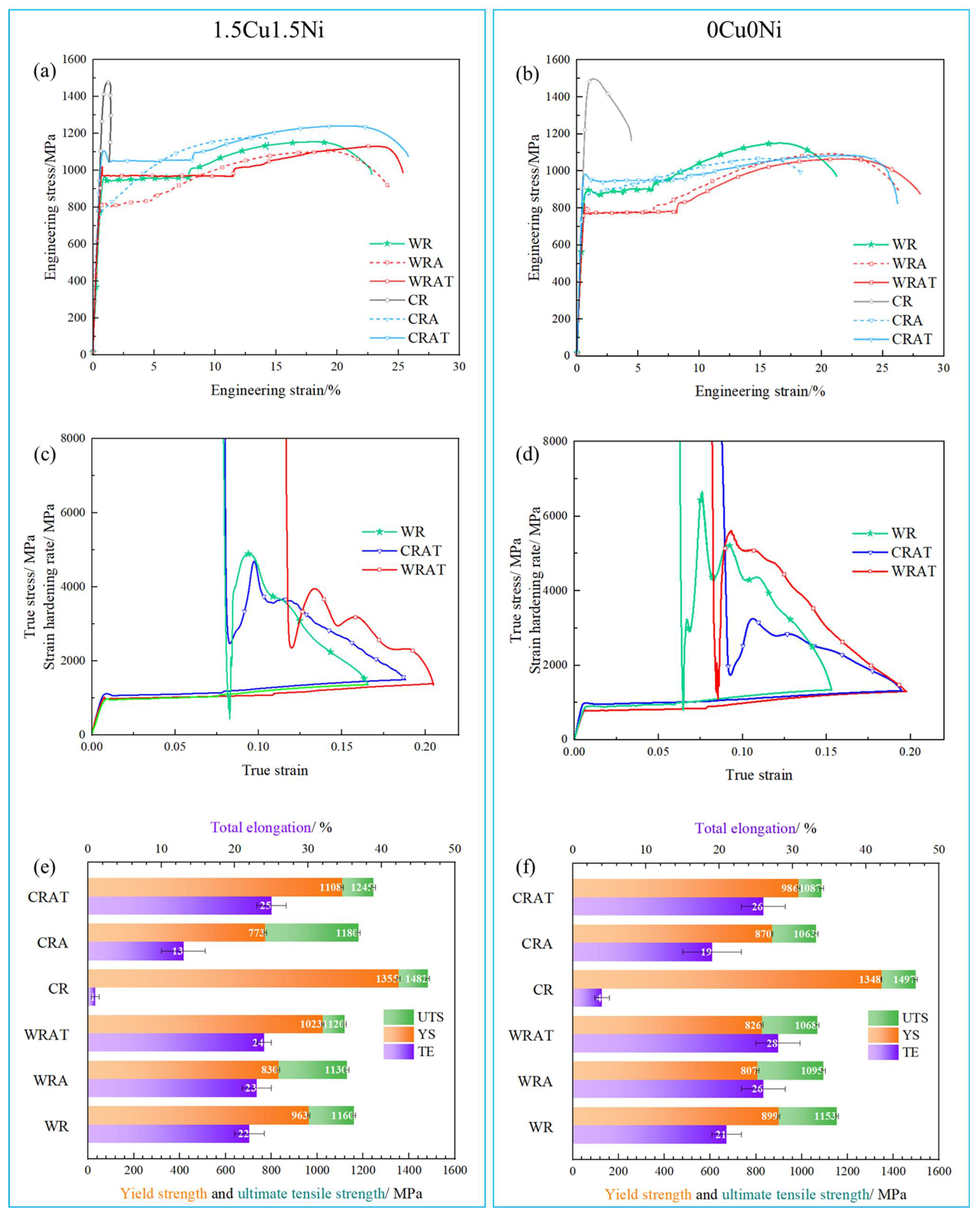
The stress–strain curves of the CR, WR, CRA, WRA, CRAT and WRAT specimens are shown in Figure 2a–d. The important tensile properties of the investigated materials are listed in Figure 2e,f. The strain hardening curves in Figure 2c,d indicate that pronounced strain hardening occurred after the yielding, which could be attributed to the TRIP effect. Generally, the 1.5Cu1.5Ni specimens showed higher yield strength and total strength than 0Cu0Ni specimens for all the investigated routes. For the CR, WR, CRA, and WRA specimens, the precipitation of Cu-rich particles was not expected, since these precipitates only occur under tempering at 500–600 °C [27]. For the CRAT and WRAT processes, the yield strengths of the 1.5Cu1.5Ni specimens were improved compared to the 0Cu0Ni specimens, which could be attributed to the precipitation of Cu-rich particles during tempering. It should be noted that although the 1.5Cu1.5Ni-WR specimen did not go through any post-rolling annealing or tempering, it already exhibited excellent tensile properties (YS 967 MPa, TS 1155 MPa, TE 23%), which were slightly better than the 0Cu0Ni-WR specimen. In the following paragraphs, the tensile properties of 1.5Cu1.5Ni-WR are compared with the annealed (1.5Cu1.5Ni-CRA and 1.5Cu1.5Ni-WRA) specimens and the annealed plus tempered (1.5Cu1.5Ni-CRA and 1.5Cu1.5Ni-WRA) specimens.
The 1.5Cu1.5Ni-CRA specimen went through intercritical annealing at 700 °C for 2 min after cold rolling. The austenite reversion during annealing could be attributed to the improved ductility compared with the 1.5Cu1.5Ni-CR specimen. However, the ductility of the 1.5Cu1.5Ni-CRA specimen was much lower than the 1.5Cu1.5Ni-WR specimen (ΔTE = −9%). As a result, the 1.5Cu1.5Ni-WR specimen exhibited better tensile properties than the 1.5Cu1.5Ni-CRA specimen. For the 1.5Cu1.5Ni-WRA specimen, the yield strength was significantly reduced (ΔYS = −138 MPa) after annealing compared with the 1.5Cu1.5Ni-WR specimen. As a result, the tensile properties of the 1.5Cu1.5Ni-WR specimen stood out when compared with the annealed (1.5Cu1.5Ni-CRA and 1.5Cu1.5Ni-WRA) specimens.
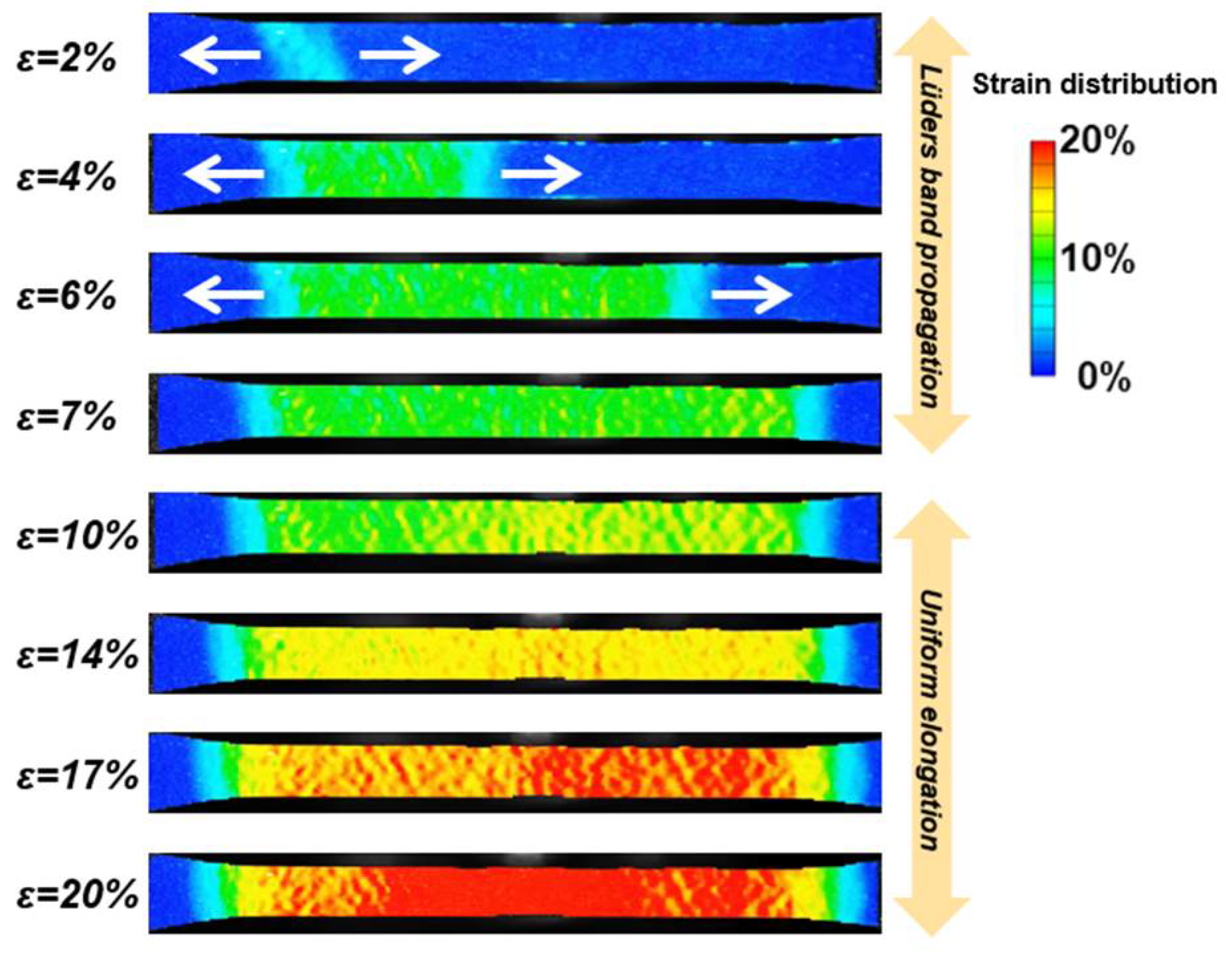
It should be noted that there should be abundant nano-precipitates in the tempered (1.5Cu1.5Ni-CRAT and 1.5Cu1.5Ni-WRAT) specimens after 500 °C tempering for 3 h [26], and the 1.5Cu1.5Ni-WR specimen is probably precipitate-free. Nevertheless, the yield strength of the 1.5Cu1.5Ni-WR specimen is close to that of the 1.5Cu1.5Ni-WRAT specimen (ΔYS = −33 MPa). The 1.5Cu1.5Ni-WRAT specimen showed improved ductility (ΔTE = 5%) compared to the 1.5Cu1.5Ni-WR specimen. All of the three 1.5Cu1.5Ni- (WR, WRAT, CRAT) specimens showed yield point elongation. The Lüders band propagation of the 1.5Cu1.5Ni-WR specimen is shown in Figure 3. To conclude, the 1.5Cu1.5Ni-WR specimens exhibited comparable tensile properties with 1.5Cu1.5Ni- (CRAT, WRAT) specimens, and the heat treatment route was significantly shortened.

3.2. Microstructure Characteristics

The austenite volume fraction before the tensile test has been obtained based on Rietveld refinement. As shown in the SY-XRD spectra in Figure 4a,b, six austenite peaks and five ferrite peaks were taken into calculation for the refinement. The calculated austenite fraction is shown in Figure 4c. For the hot- and cold-rolled conditions, there was 0 vol.% austenite in the two cold-rolled specimens (1.5Cu1.5Ni-CR and 0Cu0Ni-CR). On the contrary, the two warm-rolled specimens exhibited a pronounced austenite fraction. For the annealed and tempered specimens, the 1.5Cu1.5Ni specimens showed a higher volume fraction of austenite than the 0Cu0Ni specimens. The annealing and tempering applied after rolling increased the austenite volume fraction of the CR specimen, but showed a negative influence on the austenite fraction of WR specimens. For example, the austenite fraction of the 1.5Cu1.5Ni-CR specimen was 0 vol.%. After the applied annealing, the austenite fraction increased to 29.1 vol.% in the 1.5Cu1.5Ni-CRA specimen. After the applied tempering, the austenite fraction further increased to 33.7 vol.%. On the contrary, the austenite fractions of the 1.5Cu1.5Ni-WR, 1.5Cu1.5Ni-WRA and 1.5Cu1.5Ni-WRAT specimens were 40.6 vol.%, 39.3 vol.%, and 39.7 vol.%, respectively, which remained almost the same. A possible reason for this could be that the austenite that reverted during the soaking at 750 °C before warm rolling was retained after warm rolling, and that the amount of RA already exceeded the equilibrium austenite fraction during annealing at 700 °C, so that no extra austenite was transformed during annealing. Furthermore, the 1.5Cu1.5Ni-WR specimen (40.6 vol.%) showed more austenite fraction than the 1.5Cu1.5Ni-CRAT specimen (33.7 vol.%), and the WR route is significantly shortened compared to the CRAT route. As a result, the alloying of Cu and Ni was beneficial in increasing the RA fraction, and the WR route was more effective than the CRAT or WRAT routes in austenite reversion.
The typical morphologies of the 1.5Cu1.5Ni MMnS after rolling at different temperatures are shown in Figure 5. The hot-rolled and cold-rolled microstructures show coarse martensite laths along different directions. In comparison, the microstructure of the WR sample is more refined and more homogeneous along the rolling direction.
The microstructure morphologies of the 1.5Cu1.5Ni-WR, 1.5Cu1.5Ni-WRAT and 1.5Cu1.5Ni-CRAT specimens were obtained from the EBSD phase maps of austenite overlapped with the IQ maps of ferrite, as shown in Figure 6a–d. In the 1.5Cu1.5Ni-WRAT specimen, the austenite grains were relatively thin and elongated along the rolling direction (RD). In contrast, most austenite grains were less elongated and more equiaxed in the 1.5Cu1.5Ni-CRAT and 1.5Cu1.5Ni-WR specimens. The orientation distributions of the 1.5Cu1.5Ni-WR, 1.5Cu1.5Ni-WRAT, and 1.5Cu1.5Ni-CRAT specimens are displayed as IPFs, as shown in Figure 6e–l. The 1.5Cu1.5Ni-WR specimen did not present a dominant orientation texture for austenite or ferrite grains. For the 1.5Cu1.5Ni-WRAT specimen, the majority of austenite grains exhibited an orientation of <111>//RD, while ferrite grains mostly showed <101>//RD. In terms of the 1.5Cu1.5Ni-CRAT specimen, although most of the α grains showed an orientation of <101>//RD, similar to that of the α grains in the 1.5Cu1.5Ni-WRAT specimen, a more random orientation distribution of the former can also be observed and, at the same time, the γ orientation distribution of 1.5Cu-CRAT is very random, without any obvious texture.
As shown in Table 3, there is no noticeable difference among the three specimens regarding the austenite grain size. However, the 1.5Cu1.5Ni-WRAT specimen shows the highest aspect ratio of austenite grains. A possible reason for this is that the degree of recovery and recrystallization during cold rolling is lower than that during warm rolling, and the number of crystal defects after deformation is higher in the 1.5Cu1.5Ni-CRAT specimen, as is the stored deformation energy, which serves as the driving force for the nucleation of austenite reversion with an equiaxed shape. In contrast, during warm rolling, the comparatively high deformation temperature not only favors the retention of austenite, but also allows the partition of austenite stabilizers (e.g., C and Mn) to occur from ferrite to austenite, giving rise to an elongated and stabilized austenite phase in the 1.5Cu1.5Ni-WRAT specimen.

3.3. Dislocation Densities of the WR, WRAT, and CRAT Specimens

The dislocation densities of the developed microstructure are essential to understanding their mechanical properties. In this study, quantitative dislocation density analysis was performed for austenite and ferrite phases using the modified Williamson–Hall (MWH) method. The full-width–half-maximum (FWHM) values of individual peaks in the SYXRD spectra given in Figure 4 indicate the variations in grain size and dislocation density. The MWH equation is
Δ K 0.9 D + b π 2 ρ M ( K C ¯ 1 2 ) + O K 2 C ¯ h k l
in which K represents the multiplicative inverse of interplanar spacing (1/d), K = 2 sin θ / λ , Δ K = cos θ ( Δ 2 θ ) / λ , θ is the diffraction angle, Δ2θ is the FWHM of the diffraction peak, λ is the wavelength of the X-ray, D is the average grain size, b is the magnitude of Burgers vector of dislocations (0.254 nm and 0.252 nm in γ and α, respectively), M is a dislocation distribution parameter that depends on the effective outer cut-off radius of the dislocation (M = 2 in the present work), and C ¯ is the average contrast factor of dislocations, which can be obtained by
C ¯ = C ¯ h 00 ( 1 q H 2 )
in which C ¯ h 00 is the average contrast factor corresponding to h00 reflection. In the present work, C ¯ h 00 = 0.266 was used, based on the assumption that edge and screw dislocations are present in equal proportion. The value of q is set as 2.203. Besides this,
H 2 = h 2 k 2 + k 2 l 2 + l 2 h 2 ( h 2 + k 2 + l 2 ) 2
in which h, k and l are the Miller indices of each peak. O K 2 C ¯ h k l is a higher-order term (without meaning attached) that is not considered, since O is much smaller than the coefficient in front of K C ¯ h k l .
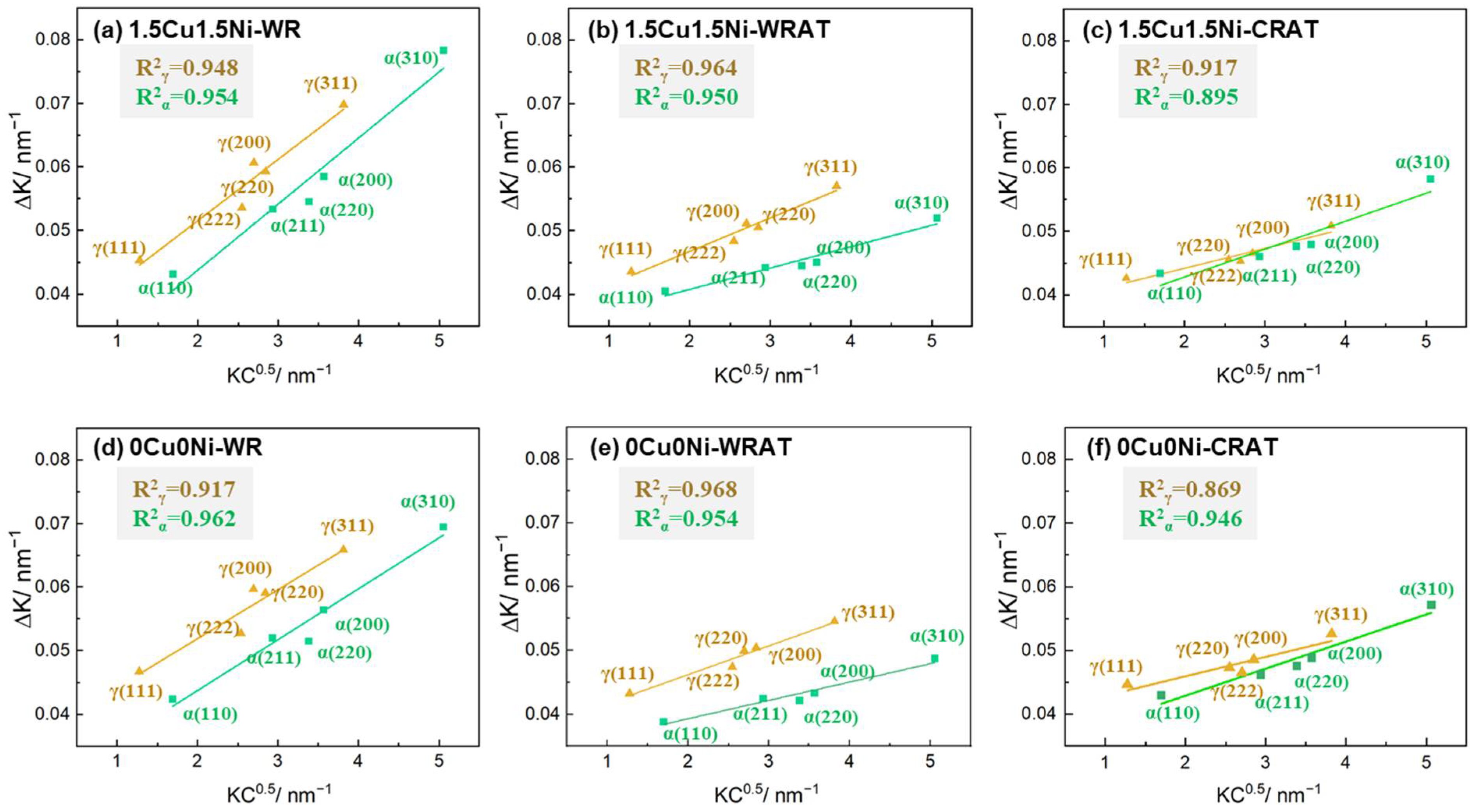
In the present work, the XRD diffraction peaks used for the calculation were γ(111), γ(200), γ(220), γ(222) and γ(311) for austenite, and α(110), α(200), α(220), α(211) and α(310) for ferrite. From the linear relationship of Δ K and K C ¯ 1 2 shown in Equation (1), it is known that the slope of the fitting curve, m, of the points obtained from corresponding (hkl) peaks can be used for the calculation of dislocation density:
ρ = 2 m 2 π M b 2
in which m is the slope of the linear fitting curve, with Figure 7 showing such a linear fit process.
The dislocation density of each sample has been summarized in Figure 8. It can be seen that the addition of Cu and Ni increased the dislocation densities of both α and γ phases in all the specimens. Furthermore, the annealing and tempering heat treatments can dramatically reduce the dislocation density in both phases of the WR samples. In the α phase of the WRAT samples, the dislocation density is nearly half that of the CRAT samples, whereas in the γ phase, the former is approximately twice as much as the latter.

3.4. Elemental Partitioning of Different TMT Specimens

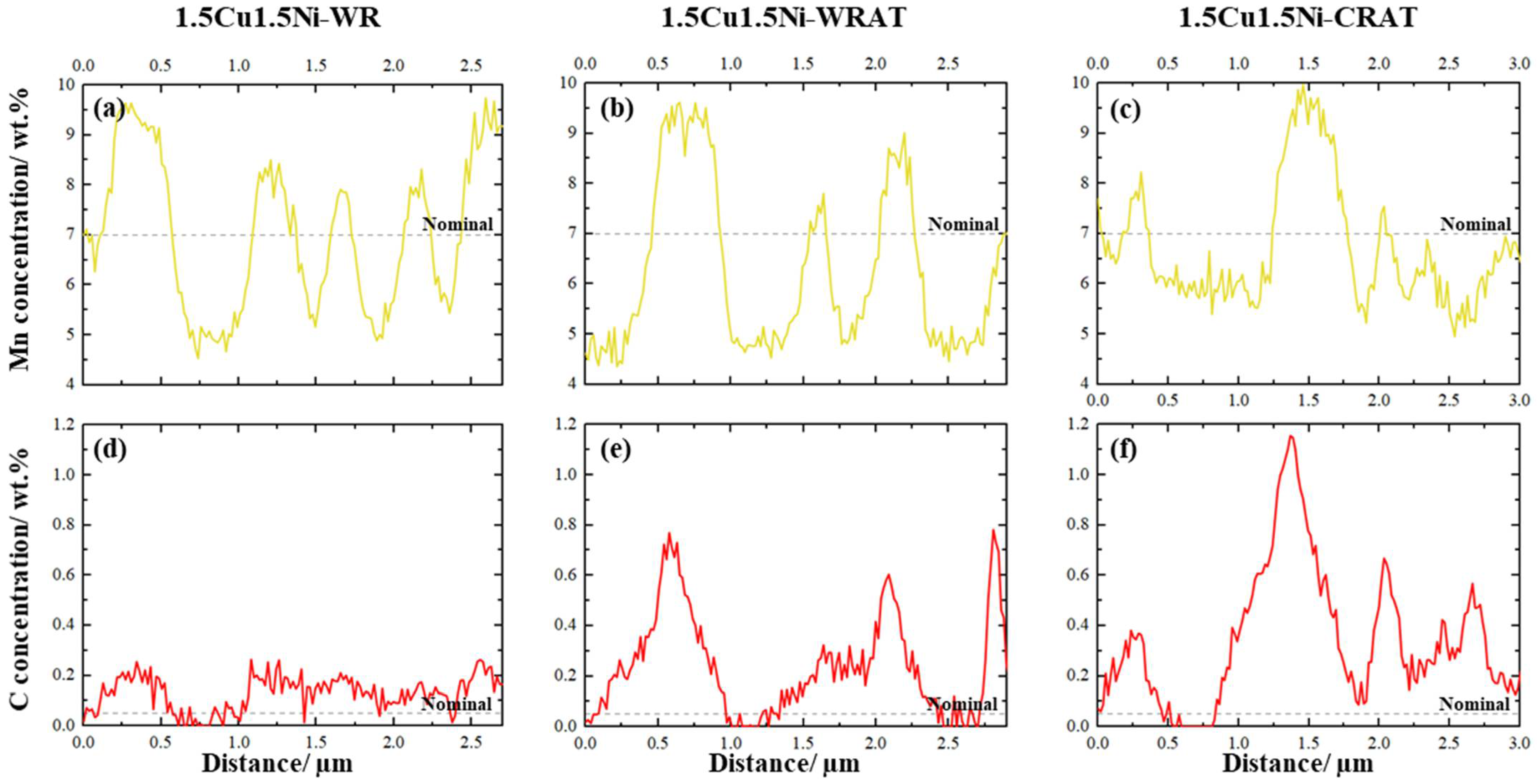
The elemental partitioning behaviors of 1.5Cu1.5Ni MMnS induced by WR, WRAT, and CRAT treatments were characterized by the EPMA line scan. Figure 9 shows the Mn and C concentration profiles across several austenite and ferrite grains. The nominal compositions of Mn and C are marked with dashed lines. It can be seen from Figure 9a–c that the Mn partitioning in these three specimens was similar, with a Mn concentration of approximately 5 wt. % in the ferrite grains and 9 wt. % in the austenite grains. However, as shown in Figure 9d–f, the C partitioning in the 1.5Cu1.5Ni-WRAT and 1.5Cu1.5Ni-CRAT specimens was much more evident than the 1.5Cu1.5Ni-WR specimen. The peak C concentration in austenite grains in the 1.5Cu1.5Ni-WR specimen was approximately 0.2 wt. %, while in the 1.5Cu1.5Ni-WRAT specimen it was approximately 0.6–0.8 wt. %, and in the 1.5Cu1.5Ni-CRAT specimen approximately 1.1 wt. %. More pronounced C partitioning in the annealed and tempered specimens was probably achieved during the long-time tempering process. The Mn atoms were difficult to partition at such a low temperature (500 °C), and the partition of C was still active.

4. Discussion

4.1. Influencing Factors of Chemical Composition and Processing on the Austenite Reversion in MMnS

It can be seen from Figure 4 that before the tensile test, the 1.5Cu1.5Ni specimens exhibited more RA than the reference alloy (0Cu0Ni) with the same heat treatment. WR enabled a pronounced RA fraction, which was not affected by the post-heat treatments. In terms of the 1.5Cu1.5Ni specimens, WR stands out with the most considerable austenite fraction of 40.6 vol.%, close to that of WRAT (39.7 vol.%). In contrast, for 0Cu0Ni, the austenite volume fraction of the WR specimen (32.3 vol.%) is comparable with that of the WRAT specimen (33.3 vol.%). Compared to warm-rolled specimens, the austenite fraction of CRAT specimens is less (33.7 vol.% and 21.0 vol.% for 1.5Cu1.5Ni and 0Cu0Ni, respectively), even though the post-rolling annealing and tempering effectively increased the volume fraction of retained austenite after cold rolling. Some reasons for this are proposed and discussed here.
Firstly, the rolling temperature was between Ac1 and Ac3 throughout the whole warm rolling process, which is favorable for the existence of austenite. In this regard, cold rolling is worse in comparison, since, on the one hand, after hot rolling, a nonequilibrium phase transformation provides a fully α’ martensite microstructure, with negligible RA, as the starting microstructure of cold rolling [2]. On the other hand, if there were any, the RA would be thermodynamically unstable at temperatures below Ac1 during cold rolling, so it is even more challenging to retain.
Secondly, the operative temperature of warm rolling between Ac1 and Ac3 results in the co-existence of austenite and ferrite, which means that during warm rolling, the dynamic element partitioning of austenite-stabilizing elements (e.g., C and Mn) from ferrite to austenite can take place, indicative of the enhancement in the stability of retained austenite during both the warm rolling and the subsequent air cooling. As shown in Figure 9, the partitioning of C and Mn to austenite during warm rolling was confirmed, implying that the austenite with higher stability can resist severe deformation. Such warm rolling-induced partitioning was also reported by Magalhães et al. [11,12]. It is worth noting that, at a higher working temperature above Ac3, hot rolling fails to facilitate the enrichment of austenite stabilizers in austenite by partitioning, owing to the formation of a single-phase austenite microstructure during rolling, which serves as an explanation for the lower stability of the austenite originating from hot rolling and the massive martensite transformation during subsequent cooling, as mentioned above.
The contribution of dynamic recrystallization to the high austenite fraction in the WR specimens cannot be ignored either, because the deformation energy was not consumed by martensitic transformation alone. Instead, part of it was also consumed by dynamic recrystallization (of ferrite, austenite, etc.), such that the amount of austenite transformed to martensite decreased. Furthermore, the WR process resulted in high dislocation density (Figure 9), which contributed to stabilizing the retained austenite [23]. With all these favorable factors, it is reasonable to believe that warm rolling has the capability of retaining a significant fraction of austenite in the microstructure.
In terms of the WRAT specimens, it can be observed that the austenite fraction is close to that of the WR specimen, as shown in Figure 4, since the phase equilibrium was nearly reached, or was approached, during WR. Meanwhile, the CRAT specimens exhibit less austenite fraction than the WR or WRAT specimens. The reduced austenite fraction in CRAT specimens is related to two factors. Firstly, the intercritical annealing temperature of the CRAT treatment was slightly lower than the soaking temperature of the WR treatment. The austenite fraction of the CRAT specimens was reduced as a result of the thermodynamic equilibrium. Secondly, the driving force accumulated during cold deformation contributes not only to ART, but also to the static recrystallization (of ferrite, retained austenite, etc.) during the following heat treatment.

4.2. Mechanical Stability of RA

To compare the mechanical stability of RA of specimens with that of different strains during tensile tests, the following equation is applied [22]:
f γ = f γ 0 exp ( k ε )
where ε is the true strain of the specimen, fγ0 and fγ represent the austenite fraction of the specimen before and after straining to ε, and k is the mechanical stability coefficient of RA. A higher value of k indicates a lower mechanical stability of RA. The true strain, at which necking starts to occur, is chosen in our calculation of k, and the results are given in Table 4. It is worth noting that the austenite fraction remains the same during the necking process because of the absence of the TRIP effect. Therefore, the fγ and ε here are considered as corresponding to each other.
What stands out from Table 4 is that the alloying of Cu and Ni, and the heat treatment, significantly influenced the mechanical stability of RA during the tensile test. The addition of Cu and Ni resulted in a higher stability of RA, implied by the lower k values, which can be ascribed to the fact that Cu and Ni both function as austenite-stabilizing elements. Besides this, the heat treatment after warm/cold rolling led to the enhanced stability of austenite during tensile testing, shown by the lower k values of WRAT and CRAT than those of the WR specimens with the same composition, which is understandable since the more intensive partitioning of C (Figure 9) during heat treatment further increased the mechanical stability of RA.
The grain size of RA is another factor that influences austenite stability. As shown in Table 3 and Table 4, for specimens with the same composition, a smaller austenite grain size often corresponds to a lower k value, suggesting higher austenite stability. Zhang et al. [28] support this phenomenon, claiming in their study on MMnS that the austenite with the smallest grain size presented the most outstanding stability. In contrast, a weaker austenite stability was observed in specimens with larger austenite grains. It is reasonable to propose that, on the other hand, static recrystallization during the post-rolling heat treatment causes austenite grain refinement. In this case, the cold-rolled specimen has more deformation energy stored as the driving force for static recrystallization than the warm-rolled specimen, such that the austenite grain refinement effect also appears more prominent via the more pronounced static recrystallization, which is supported by the lower k values (13.15 for 1.5Cu1.5Ni and 14.02 for 0Cu0Ni) of CRAT specimens than those (14.52 for 1.5Cu1.5Ni and 21.71 for 0Cu0Ni) of WRAT. On the other hand, for the specimens with alloying of Cu and Ni, the drag effect exerted by the Cu and Ni solute atoms on grain boundaries may also contribute to the austenite grain refinement, as implied by the lower k values of the Cu/Ni-alloyed specimens compared to those with the same treatment but without Cu and Ni.

5. Conclusions

In this study, various thermomechanical treatments of warm rolling have been studied for medium-Mn steels (MMnS) containing Cu and Ni, with the aim of achieving excellent tensile properties with a compact processing route. The volume fractions and mechanical stabilities of retained austenite, the dislocation densities, and the tensile properties of the warm-rolled (WR) specimen were investigated and compared with the annealed and tempered (WRAT, CRAT) specimens. The key conclusions are as follows:
(1)
The investigated warm rolling processing route provided excellent tensile properties to the 1.5Cu1.5Ni-WR specimen, with a high yield strength of 967 MPa, a total strength of 1155 MPa, and total elongation of 23%;
(2)
The microstructure of the 1.5Cu1.5Ni-WR specimen contained 40.6 vol.% austenite. The warm rolling process preserved a large number of dislocations and provided a high fraction of retained austenite, owing to the lack of static recrystallization and the strong elemental partitioning;
(3)
The high strength of the 1.5Cu1.5Ni-WR specimen can be attributed to the deformed ferrite grains and the increased mechanical stability of the ultra-fine austenite grains with an inherent large dislocation density. The extraordinary ductility of the 1.5Cu1.5Ni-WR specimen was a consequence of the pronounced TRIP effect and the postponement of necking in the ultra-fine microstructure;
(4)
The proposed WR route delivers comparable tensile properties to the WRAT and CRAT routes, but the processing route is significantly shorter.

Author Contributions

Conceptualization, Z.X.; data curation, J.L.; formal analysis, T.A.; funding acquisition, W.B.; investigation, X.S. and S.R.; methodology, Z.X. and T.A.; project administration, W.S. and W.B.; resources, W.S.; software, X.S.; supervision, W.B.; writing—original draft, Z.X. and J.L. All authors have read and agreed to the published version of the manuscript.

Funding

This research was funded by the German research foundation (DFG), grant number BL 402/49-1. Zigan Xu was funded by the China scholarship council (CSC), grant number 201706080011.

Data Availability Statement

Not applicable.

Acknowledgments

We acknowledge DESY (Hamburg, Germany), a member of the Helmholtz Association HGF, for the provision of experimental facilities. Parts of this research were carried out at beamline P02.1 of PETRA III (proposal No. I-20191416), and we would like to thank Martin Etter and Alexander Schökel for their support at beamline in SY-XRD measurement. We also thank David Lenz for the kind support on the DIC measurement and data analysis.

Conflicts of Interest

The authors declare no conflict of interest.

References

  1. Raabe, D.; Sun, B.; Silva, A.d.; Gault, B.; Yen, H.-W.; Sedighiani, K.; Sukumar, P.T.; Filho, I.R.S.; Katnagallu, S.; Jägle, E.; et al. Current Challenges and Opportunities in Microstructure-Related Properties of Advanced High-Strength Steels. Metall. Mater. Trans. A 2020, 51, 5517–5586. [Google Scholar] [CrossRef]
  2. Lee, Y.-K.; Han, J. Current opinion in medium manganese steel. Mater. Sci. Technol. 2015, 31, 843–856. [Google Scholar] [CrossRef]
  3. Allam, T.; Bleck, W.; Klinkenberg, C.; Kintscher, B.; Krupp, U.; Rudnizki, J. The continuous casting behavior of medium manganese steels. J. Mater. Res. Technol. 2021, 15, 292–305. [Google Scholar] [CrossRef]
  4. Ma, Y. Medium-manganese steels processed by austenite-reverted-transformation annealing for automotive applications. Mater. Sci. Technol. 2017, 33, 1713–1727. [Google Scholar] [CrossRef]
  5. Hu, B.; Luo, H.; Yang, F.; Dong, H. Recent progress in medium-Mn steels made with new designing strategies, a review. J. Mater. Sci. Technol. 2017, 33, 1457–1464. [Google Scholar] [CrossRef]
  6. Speer, J.; Rana, R.; Matlock, D.; Glover, A.; Thomas, G.; De Moor, E. Processing Variants in Medium-Mn Steels. Metals 2019, 9, 771. [Google Scholar] [CrossRef] [Green Version]
  7. Suh, D.-W.; Kim, S.-J. Medium Mn transformation-induced plasticity steels: Recent progress and challenges. Scr. Mater. 2017, 126, 63–67. [Google Scholar] [CrossRef]
  8. Mishra, G.; Chandan, A.K.; Kundu, S. Hot rolled and cold rolled medium manganese steel: Mechanical properties and microstructure. Mater. Sci. Eng. A 2017, 701, 319–327. [Google Scholar] [CrossRef]
  9. Kozasu, I.; Shimizu, T.; Kubota, H. Recrystallization of Austenite of Si-Mn Steels with Minor Alloying Elements after Hot Rolling. ISIJ Int. 1971, 11, 367–375. [Google Scholar] [CrossRef] [Green Version]
  10. Tamura, I.; Ouchi, C.; Tanaka, T.; Sekine, H. Thermomechanical Processing of High-Strength Low-Alloy Steels; Butterworths: London, UK, 1988. [Google Scholar]
  11. Magalhães, A.S.; Moutinho, I.D.; Oliveira, I.R.; Ferreira, A.O.V.; Alves, D.S.; Santos, D.B. Ultrafinegrained Microstructure in a Medium Manganese Steel after Warm Rolling without Intercritical Annealing. ISIJ Int. 2017, 57, 1121–1128. [Google Scholar] [CrossRef] [Green Version]
  12. Magalhães, A.S.; Santos, C.E.d.; Ferreira, A.O.V.; Alves, D.S.; Santos, D.B. Analysis of medium manganese steel through cold-rolling and intercritical annealing or warm-rolling. Mater. Sci. Technol. 2018, 11, 1–14. [Google Scholar] [CrossRef]
  13. Zhao, X.; Shen, Y.; Qiu, L.; Liu, Y.; Sun, X.; Zuo, L. Effects of Intercritical Annealing Temperature on Mechanical Properties of Fe-7.9Mn-0.14Si-0.05Al-0.07C Steel. Materials 2014, 7, 7891–7906. [Google Scholar] [CrossRef] [Green Version]
  14. Hu, B.; Luo, H. A strong and ductile 7Mn steel manufactured by warm rolling and exhibiting both transformation and twinning induced plasticity. J. Alloys Compd. 2017, 725, 684–693. [Google Scholar] [CrossRef]
  15. Hodgson, P.; Cai, M.H.; Rolfe, B. Hot Forming of Medium Mn Steels with TRIP Effect. In Advanced High Strength Steel and Press Hardening; World Scientific: Singapore, 2016; pp. 27–34. [Google Scholar]
  16. Hawkins, D.N.; Shuttleworth, A.A. The effect of warm rolling on the structure and properties of a low-carbon steel. J. Mech. Work. Technol. 1979, 2, 333–345. [Google Scholar] [CrossRef]
  17. Allam, T.; Guo, X.; Sevsek, S.; Lipińska-Chwałek, M.; Hamada, A.; Ahmed, E.; Bleck, W. Development of a Cr-Ni-V-N Medium Manganese Steel with Balanced Mechanical and Corrosion Properties. Metals 2019, 9, 705. [Google Scholar] [CrossRef] [Green Version]
  18. Kong, H.; Liu, C. A Review on Nano-Scale Precipitation in Steels. Technologies 2018, 6, 36. [Google Scholar] [CrossRef] [Green Version]
  19. Allam, T.; Guo, X.; Lipińska-Chwałek, M.; Hamada, A.; Ahmed, E.; Bleck, W. Impact of precipitates on the hydrogen embrittlement behavior of a V-alloyed medium-manganese austenitic stainless steel. J. Mater. Res. Technol. 2020, 9, 13524–13538. [Google Scholar] [CrossRef]
  20. Shyamal, S.; Farahani, M.G.; Allam, T.; Hamada, A.S.; Haase, C.; Kömi, J.I.; Chakraborti, P.C.; Sahu, P. Activation of a hybrid twinning mechanism in a Cr-Ni-Si-V-N medium manganese austenitic steel containing precipitates. Scr. Mater. 2021, 192, 83–88. [Google Scholar] [CrossRef]
  21. Kapoor, M.; Isheim, D.; Ghosh, G.; Vaynman, S.; Fine, M.E.; Chung, Y.-W. Aging characteristics and mechanical properties of 1600MPa body-centered cubic Cu and B2-NiAl precipitation-strengthened ferritic steel. Acta Mater. 2014, 73, 56–74. [Google Scholar] [CrossRef]
  22. Zou, Y.; Xu, Y.B.; Han, D.T.; Hu, Z.P.; Misra, R.D.K.; Cao, L.F.; Song, H. Combined contribution of Cu-rich precipitates and retained austenite on mechanical properties of a novel low-carbon medium-Mn steel plate. J. Mater. Sci. 2019, 54, 3438–3454. [Google Scholar] [CrossRef]
  23. Yan, S.; Liang, T.; Chen, J.; Li, T.; Liu, X. A novel Cu-Ni added medium Mn steel: Precipitation of Cu-rich particles and austenite reversed transformation occurring simultaneously during ART annealing. Mater. Sci. Eng. A 2019, 746, 73–81. [Google Scholar] [CrossRef]
  24. Tsuchiyama, T.; Yamamoto, S.; Hata, S.; Murayama, M.; Morooka, S.; Akama, D.; Takaki, S. Plastic deformation and dissolution of ε-Cu particles by cold rolling in an over-aged particle dispersion strengthening Fe-2mass%Cu alloy. Acta Mater. 2016, 113, 48–55. [Google Scholar] [CrossRef] [Green Version]
  25. Gražulis, S.; Chateigner, D.; Downs, R.T.; Yokochi, A.F.T.; Quirós, M.; Lutterotti, L.; Manakova, E.; Butkus, J.; Moeck, P.; Le Bail, A. Crystallography Open Database—An open-access collection of crystal structures. J. Appl. Crystallogr. 2009, 42, 726–729. [Google Scholar] [CrossRef] [PubMed]
  26. Lutterotti, L. Maud: A Rietveld analysis program designed for the internet and experiment integration. Acta Crystallogr. A 2000, 56, s54. [Google Scholar] [CrossRef] [Green Version]
  27. Kong, H.J.; Yang, T.; Chen, R.; Yue, S.Q.; Zhang, T.L.; Cao, B.X.; Wang, C.; Liud, W.H.; Luance, J.H.; Jiao, Z.B.; et al. Breaking the strength-ductility paradox in advanced nanostructured Fe-based alloys through combined Cu and Mn additions. Scr. Mater. 2020, 186, 213–218. [Google Scholar] [CrossRef]
  28. Zhang, Y.; Wang, L.; Findley, K.O.; Speer, J.G. Influence of Temperature and Grain Size on Austenite Stability in Medium Manganese Steels. Metall. Mater. Trans. A 2017, 48, 2140–2149. [Google Scholar] [CrossRef]
Figure 1. The rolling and heat treatment routes of WR (warm-rolled) specimens and CR (hot-rolled then cold-rolled) specimens.
Metals 11 01888 g001
Figure 2. Uniaxial tensile tests of the investigated materials. (a,b) Engineering stress–strain curves, (c,d) true stress–strain curves, and (e,f) values of yield strength, ultimate tensile strength and total elongation of 1.5Cu1.5Ni and 0Cu0Ni alloys, respectively.
Metals 11 01888 g002
Figure 3. Evolution of strain distribution along the gauge section of the 1.5Cu1.5Ni-WR specimen during tensile deformation at different engineering strain (ε) levels.
Metals 11 01888 g003
Figure 4. SYXRD spectra of (a) 1.5Cu1.5Ni and (b) 0Cu0Ni specimens; (c) austenite fraction of the specimens.
Metals 11 01888 g004
Figure 5. The morphologies of 1.5 Cu1.5Ni MMnS after (a) hot rolling, (b) cold rolling, and (c) warm rolling.
Metals 11 01888 g005
Figure 6. EBSD analysis of the investigated specimens. (ad) Phase maps of austenite (in red) overlapped with IQ maps of ferrite; (eh) inverse pole figure (IPF) of austenite; (il) IPF of ferrite in the 1.5Cu1.5Ni-CRAT, 1.5Cu1.5Ni-WRAT, 1.5Cu1.5Ni-WR, and 0Cu0Ni-WR specimens, respectively.
Metals 11 01888 g006
Figure 7. Linear fit analysis of the data points obtained from SYXRD peaks, which was utilized to estimate the dislocation density (ac) for 1.5Cu1.5Ni and (df) 0Cu0Ni specimens.
Metals 11 01888 g007
Figure 8. Summary of dislocation density in γ and α phases of the investigated specimens.
Metals 11 01888 g008
Figure 9. Elemental distribution analysis in different thermomechanical heat-treated samples of 1.5Cu1.5Ni by means of EPMA line scans across austenite and ferrite grains. (ac) Mn concentration profiles, and (df) C concentration profiles in WR, WRAT and CRAT states, respectively.
Metals 11 01888 g009
Table 1. Chemical composition of the investigated alloys (chemical compositions in wt. %, transformation temperatures in °C).
CSiMnPSNiMoCuAlNAc1Ac3
0Cu0Ni0.051.57.00.0050.0040.010.510.011.50.0066001030
1.5Cu1.5Ni0.071.47.00.0050.0041.480.501.471.50.006588940
Table 2. The treatment schedules of the MMnS specimens.
SpecimenThermo-Mechanical Treatment
WRWarm rolling
WRAWarm rolling + Annealing
WRATWarm rolling + Annealing + Tempering
CRHot rolling + Cold rolling
CRAHot rolling + Cold rolling + Annealing
CRATHot rolling + Cold rolling + annealing + Tempering
Table 3. Average equivalent circular diameter (ECD) and aspect ratio of austenite grains of 1.5Cu1.5Ni- (WR, WRAT, and CRAT) specimens.
1.5Cu1.5Ni-WR1.5Cu1.5Ni-WRAT1.5Cu1.5Ni-CRAT
Average austenite ECD/μm0.450.380.40
Average austenite grain aspect ratio1.913.882.31
Table 4. k values of the 1.5Cu1.5Ni and 0Cu0Ni specimens.
1.5Cu1.5Ni-CRAT1.5Cu1.5Ni-WR1.5Cu1.5Ni-WRAT0Cu0Ni-CRAT0Cu0Ni-WR0Cu0Ni-WRAT
Austenite fraction before tensile test/%33.7440.5739.6720.9632.3333.28
Austenite fraction after fracture/%2.851.272.051.290.190.47
True strain before necking0.190.170.200.200.150.20
k13.1520.9914.5214.0233.5121.71
Publisher’s Note: MDPI stays neutral with regard to jurisdictional claims in published maps and institutional affiliations.