Article

A Structured Approach for the Design and Manufacturing of Titanium Cranial Prostheses via Sheet Metal Forming

by
Gianfranco Palumbo
1,*,
Giuseppina Ambrogio
2,
Alberto Crovace
3,
Antonio Piccininni
1,
Angela Cusanno
1,
Pasquale Guglielmi
1,
Luigi De Napoli
2 and
Giuseppe Serratore
2
1
Department of Mechanics, Mathematics and Management, Polytechnic University of Bari, Via Orabona 4, 70125 Bari, Italy
2
Department of Mechanical, Energy and Management Engineering, University of Calabria, 87036 Rende, Italy
3
Department of Basic Medical Sciences, Neuroscience and Sense Organs, University of Bari Aldo Moro, Piazza Umberto I 1, 70121 Bari, Italy
*
Author to whom correspondence should be addressed.
Metals 2022, 12(2), 293; https://doi.org/10.3390/met12020293
Submission received: 30 December 2021 / Revised: 26 January 2022 / Accepted: 1 February 2022 / Published: 8 February 2022
(This article belongs to the Special Issue Tube and Sheet Metal Forming Processes and Applications)

Abstract

:
Currently, the growing need for highly customized implants has become one of the key aspects to increase the life expectancy and reduce time and costs for prolonged hospitalizations due to premature failures of implanted prostheses. According to the literature, several technological solutions are considered suitable to achieve the necessary geometrical complexity, from the conventional subtractive approaches to the more innovative additive solutions. In the case of cranial prostheses, which must guarantee a very good fitting of the region surrounding the implant in order to minimize micromotions and reduce infections, the need of a product characterized by high geometrical complexity combined with both strength and limited weight, has pushed the research towards the adoption of manufacturing processes able to improve the product’s quality but being fast and flexible enough. The attention has been thus focused in this paper on sheet metal forming processes and, namely on the Single Point Incremental Forming (SPIF) and the Superplastic Forming (SPF). In particular, the complete procedure to design and produce titanium cranial prostheses for in vivo tests is described: starting from Digital Imaging and COmmunications in Medicine (DICOM) images of the ovine animal, the design was conducted and the production process simulated to evaluate the process parameters and the production set up. The forming characteristics of the prostheses were finally evaluated in terms of thickness distributions and part’s geometry. The effectiveness of the proposed methodology has been finally assessed through the implantation of the manufactured prostheses in sheep.

1. Introduction

The healthcare sector must continually deal with aspects of economic nature: the minimization of both the surgical timing and the complete recovery of the patient represents one of the primary objectives in this regard. This goal has led to continuous progress and innovations with the clear aim of obtaining highly performing implants for the individual patient. In light of this, one of the most important challenges involving the field of medicine is represented by the manufacture of highly customized prosthetic implants able to restore to the patient both the functionality and the natural conformation of the damaged part [1]. The need to perfectly reproduce the bone conformation of the reference patient requires a reliable procedure based on certified protocols that guarantees the perfect fitting between the prosthetic implant and the host area to be healed [2].
In this scenario, all the aspects involved are equally essential, starting from the appropriate choice of the prosthesis material, passing through the acquisition and manipulation of the damaged area geometry, up to the most appropriate manufacturing technology. With reference to the fabrication of cranial prostheses, there are several proofs of the importance deriving from the use of different Computer Aided Design (CAD) and advanced production platforms [3]. In fact, CAD tools combined with advanced patient scanning techniques have drastically transformed the process of designing prosthetic devices, effectively replacing the more traditional manual approaches based on cast and invasive techniques. In addition, these methods have made it possible to reduce costs and response times [4,5]. Moreover, typical materials adopted for biomedical applications must meet different requirements such as: (i) a certain chemical composition to avoid adverse tissue reactions, (ii) excellent resistance to degradation in the case of permanent prostheses, (iii) load-bearing capacities, (iv) capability to absorb the impacts and (v) good wear resistance for prostheses involved in reciprocal sliding [6].
In this context, metallic materials such as titanium (Ti) alloys, thanks to their capability to fully match the above-mentioned requirements, appear to be promising candidates. Such alloys, in fact, are constantly growing in terms of use in the biomedical field [7] due to their high biocompatibility, excellent resistance characteristics coupled with an appropriate elastic modulus, as well as a high resistance to corrosion (even if compared to the performing chromium-cobalt alloys) [8,9]. The best fitting between the patient’s anatomy and the geometry of the prosthesis, as well as required by aesthetic aspects, is motivated by the need to minimize the risk of infection due to micromotions between the implant and the surrounding bone [10].
For all these aspects, in addition to motivating the manufacture of complex shapes (e.g., very small radii, complex profiles and, in some cases, the presence of undercuts), customized prostheses require prohibitive tolerances for most of the manufacturing processes. Innovative processes, such as Single Point Incremental Forming (SPIF) and Superplastic Forming (SPF) can be considered as viable solutions. In fact, as demonstrated in previous studies, titanium custom prostheses can be successfully manufactured by both SPF and SPIF [11,12].
During the SPF process a metal sheet is plastically deformed at a high temperature by means of a pressurized gas. Specifically, this type of manufacturing process is intended for materials capable of emphasizing their deformation properties under appropriate operating conditions both in terms of temperature and strain rate [8]. Furthermore, SPF is a cost-effective method of producing a small to medium number of complex parts obtained with expensive materials and low formability at room temperature [13]. The process can be made more competitive by adopting less expensive tools (for example ceramic dies). The process temperature and gas pressure must be suitably selected according to the geometry and the material. For this scope, a numerical/experimental approach is fundamental during the whole design process. In fact, to obtain a sound complex component, an optimized manufacturing process involves a Finite Element (FE) modelling capable to correctly predict the alloy behaviour [14,15,16].
SPIF is based on the idea to apply a plastic deformation on a flat sheet, clamped at its periphery, by a rotating tool which describes concentric and decreasing spirals reproducing the 3D profile of the desired geometry. In this way, the material is incrementally stretched, up to reach the final shape [17]. Additionally, in this case the process design is a critical issue since the quality of the results, in terms of minimum thickness and accuracy, are strongly affected by the tool trajectory: parameters such as tool pitch (p), wall inclination angle (α), or the 3D shape positioning with respect to the flat surface need to be properly calibrated in order to optimize the quality of the formed part [18]. For this reason, when a complex profile has to be manufactured, a numerical/experimental approach is suitable for calibrating the above-mentioned parameters. Nevertheless, SPIF is a really cheap technology for producing small batch and, mainly, single part such as in custom made prosthesis application since it does not require any additional dedicated equipment but only general-purpose tool and clamping frame [19].
The aim of the present work is to provide an effective methodology for the design and subsequent fabrication of a customized cranial prosthesis in Ti6Al4V-ELI, validated by means of in vivo tests. In particular, a numerical/experimental design method was proposed for two different innovative sheet metal forming processes (SPF and SPIF) aimed to the fabrication of the prosthetic implants.
The Computed Tomography (CT) scan images were used to generate a three-dimensional model of the sheep’s damaged skull. Such geometrical acquired data were properly modified via CAD and allowed to obtain the target geometry on which the study was based. For both investigated manufacturing processes, a Finite Element approach was used to: (i) design the gas pressure (for the SPF process); (ii) define the tool trajectory (for the SPIF process). The post forming characteristics, such as thickness distributions and the shape accuracy of the prostheses, were also evaluated. Finally, the in vivo response of the prostheses manufactured using both the processes was assessed by means of histological analyses on tissues extracted after 3 and 6 months from 16 sheep in which they were implanted.

2. Materials and Methods

2.1. Investigated Materials
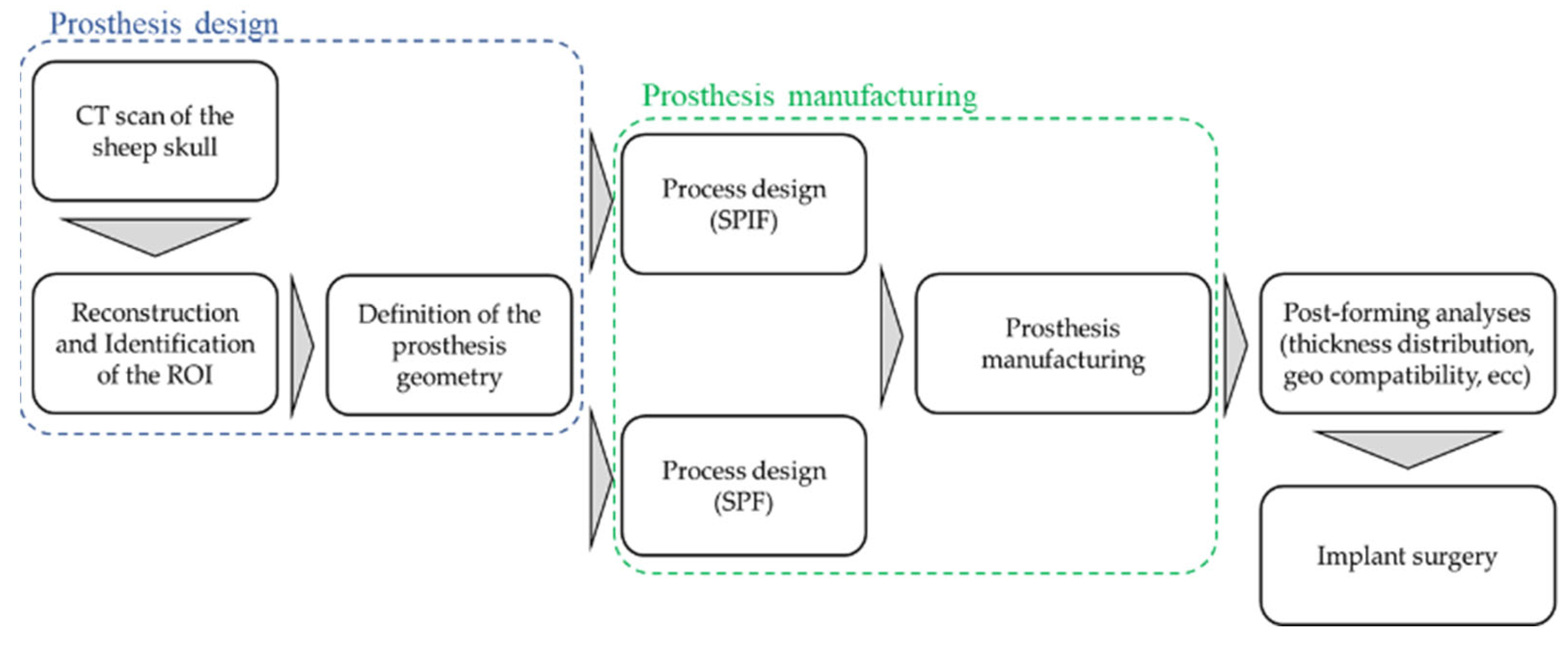
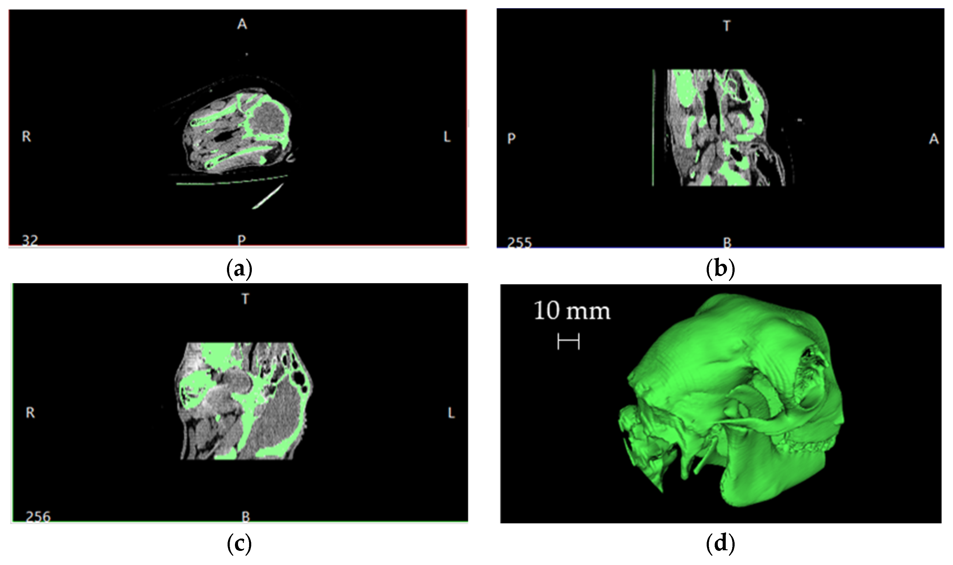
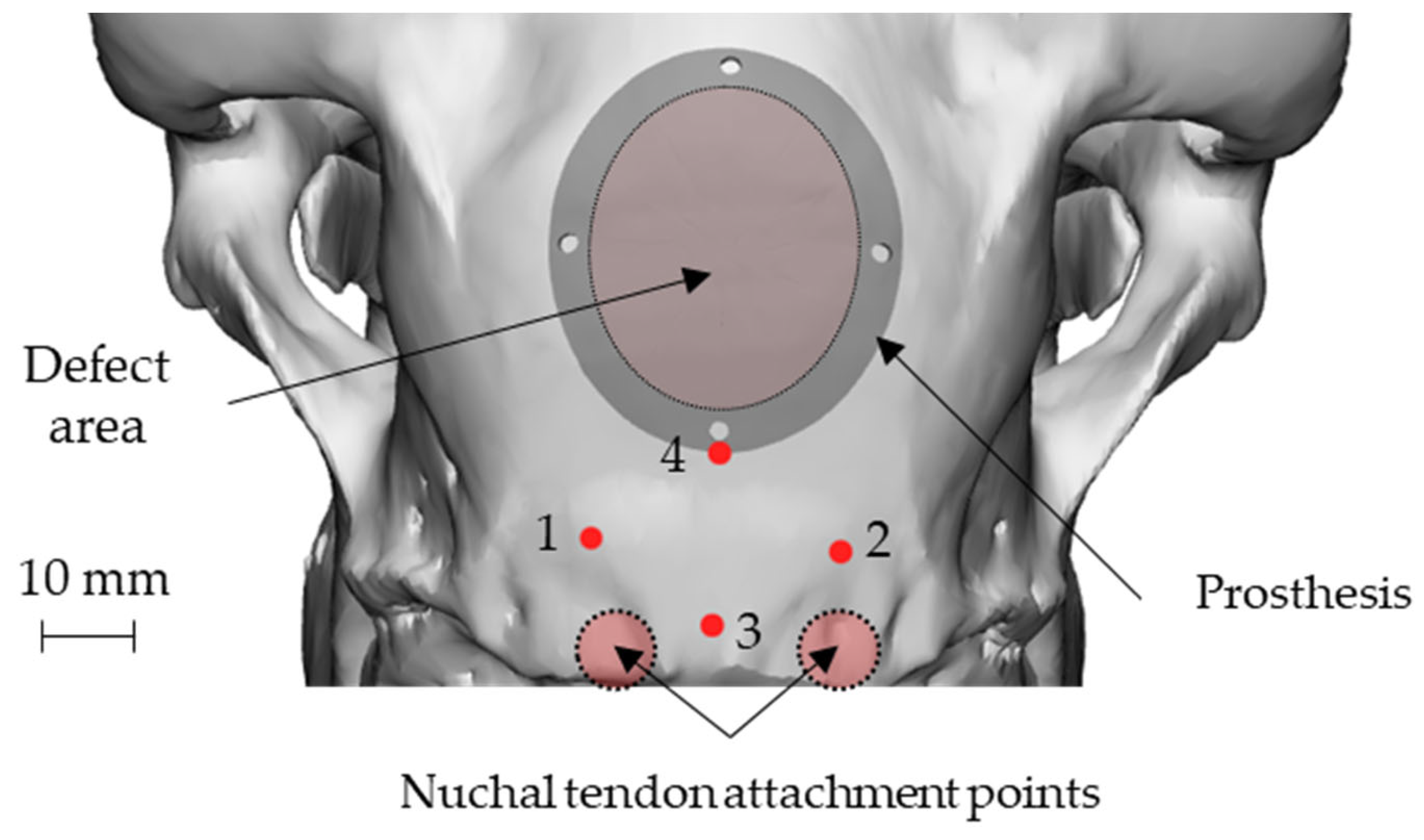
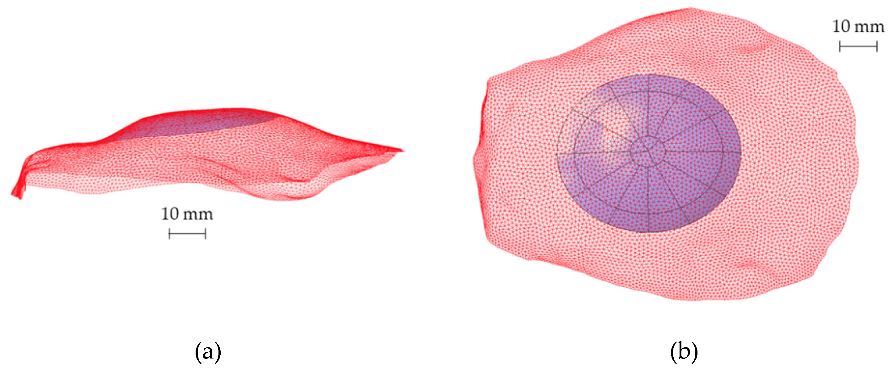
For all the activities involved in the present work the extra low interstitial titanium alloy Ti6Al4V-ELI (thickness: 1 mm) was used. The chemical composition of the investigated material is reported in Table 1.

2.2. Methodology

The whole design chain is described through the flowchart in Figure 1: starting from the CT scan of the sheep skull, the Region of Interest (ROI) was then identified, and the bone surface acquired.
The CAD reconstruction of the bone region (where the defect had to be intentionally created) represented the starting point for the design of the prosthesis geometry that, in turns, was the input data for the manufacturing process design by means of an FE-based approach. Prostheses were then manufactured—using both the SPF and the SPIF process—according to the results of the numerical simulations and finally implanted.
The starting point, after the CT scan, was the Digital Imaging and COmmunications in Medicine (DICOM) manipulation to obtain the 3D model of the skull. Figure 2 shows a typical overview resulting from the imported DICOM files into a dedicated software together with the reconstruction of the skull volume (in the bottom right corner).
This volume was then exported in the Standard Triangulation Language (STL) format. The data, represented by a point cloud, were subsequently imported and processed with a CAD software. When required, these points were divided into significant groups and, if necessary, filtered. However, the goal was to obtain a virtual model of the portion of the skull on which the prosthesis had to be implanted (ROI), fundamental for the virtual modelling of the defect to be intentionally created. Therefore, from this point, only the surface correspondent to the ROI was considered for subsequent manipulation.
An elliptical damage geometry was defined, characterized by the dimension of the largest and smallest axes equal to 34 mm and 28 mm, respectively. The identification of the damaged zone, under the advice of the surgeon, was conducted by taking as landmarks four points: points 1 and 2 identify an area immediately adjacent to the point of attachment of the nuchal tendons to the skull, whereas points 3 and 4 identify the sagittal plane. In this way, the prosthetic geometry (also elliptical) was characterized by such a positioning that its major axis will be oriented according to the just-defined sagittal plane, and the lower point is located near the point 4, as reported in Figure 3.
Subsequently, to define the CAD model of the prosthesis, the analytical surfaces close to the ROI were reconstructed starting from the obtained points. Figure 4 shows the reconstructed surface geometry compared with the original point cloud (red mesh) to verify the accuracy of the whole routine.
The prosthesis geometry was designed as elliptical by enlarging the value of the main axes from the elliptical damage up to 42 mm and 36 mm. The final 3D model of the prosthesis was obtained by making a thickening of this surface.
The approach of skull geometry reconstruction was also used to create a customized “guiding mask”, therefore perfectly respectful of bone geometry, to guide the surgeon during the intentional defect creation, and also to make the prosthesis positioning highly accurate. Since this mask was made on the specific anatomy of the skull, it minimized the error of positioning by the surgeon: in fact, being the position of the mask completely univocal with respect to the cranial case, such an approach made the operations of generating the damage highly accurate and less affected by positioning errors. Figure 5 shows the guiding mask and its position on the skull together with the geometry of the defect.
Figure 6 shows the final geometry of the prosthesis placed on the skull using point 4 as reference. The four holes visible on the prosthesis coincided in position and size with those present on the guiding mask. The role of the mask, in addition to guiding the surgeon during the defect creation, could also help to create the holes for the implant anchorage, thus allowing the correct positioning of the implant (Figure 3).

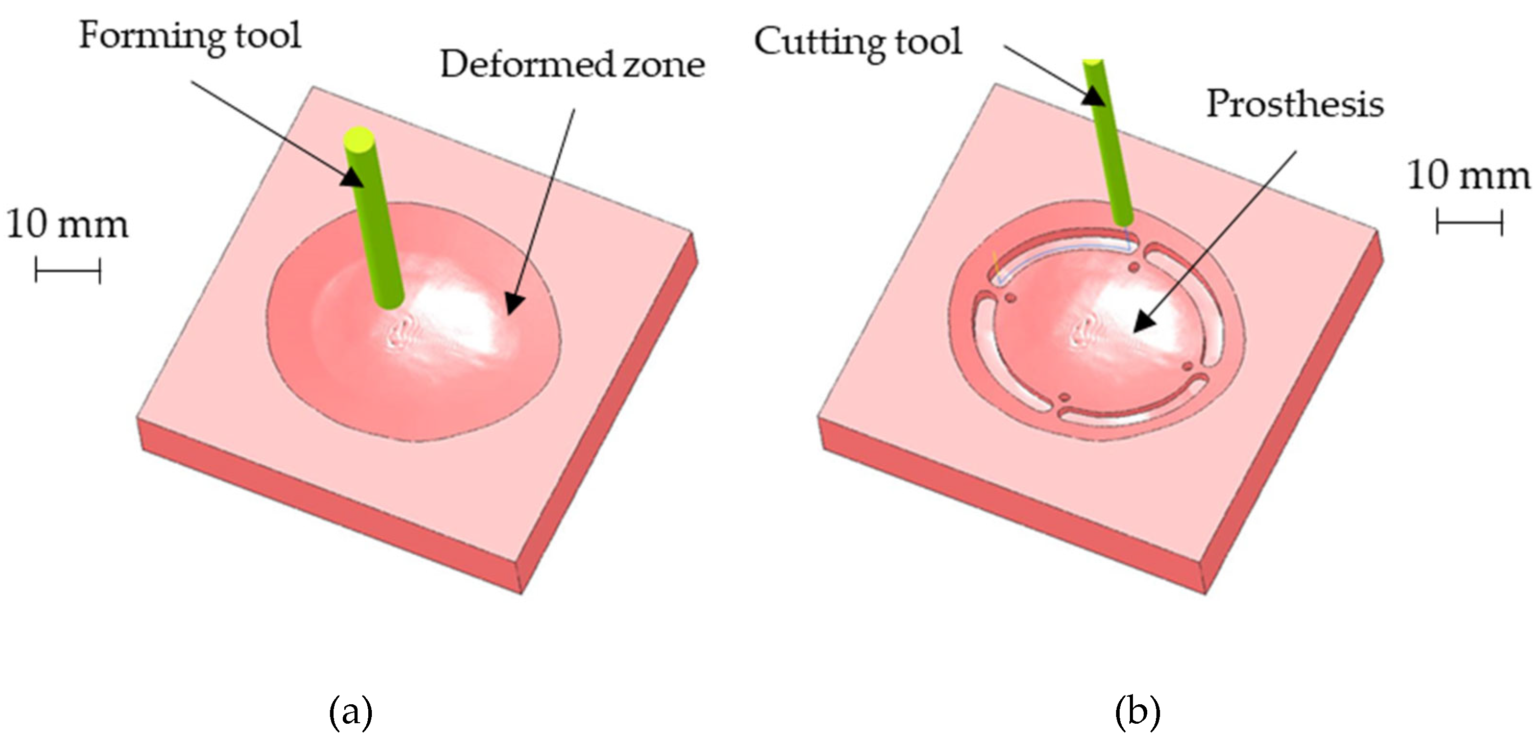
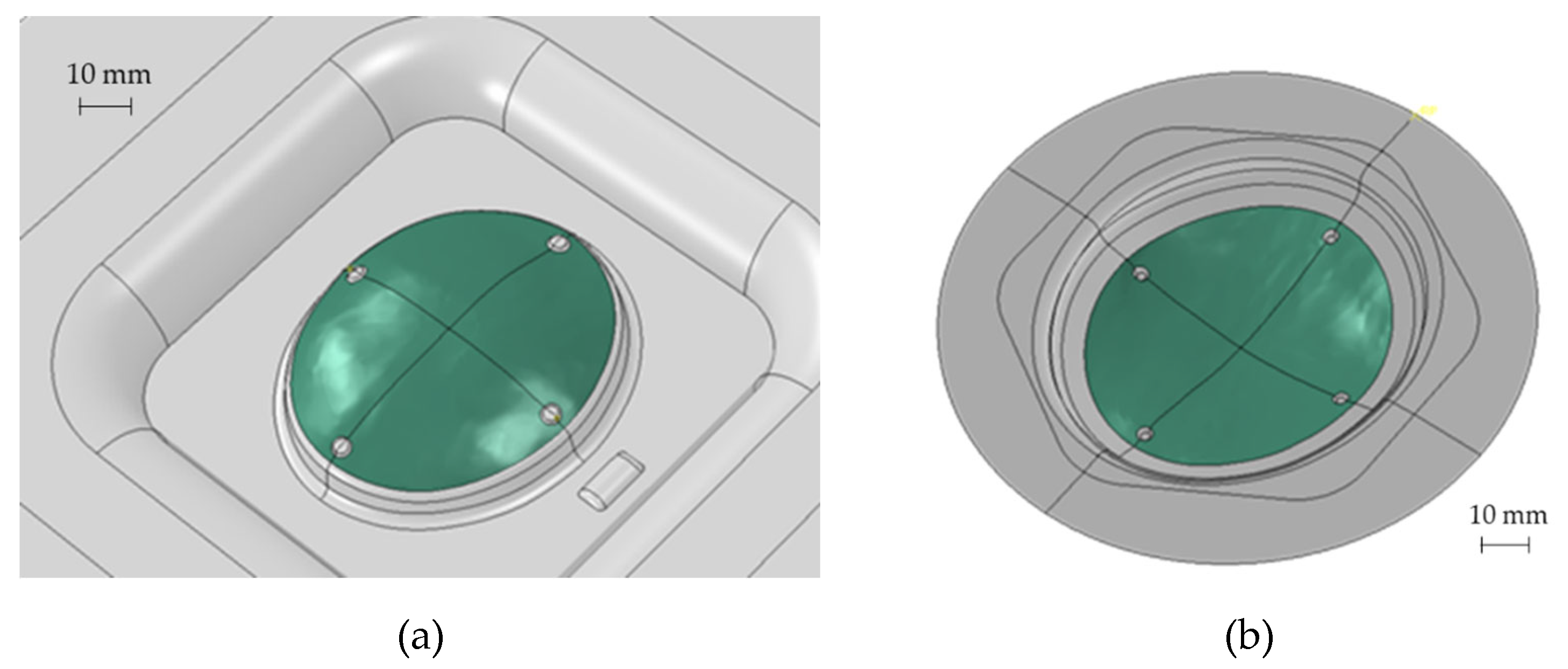
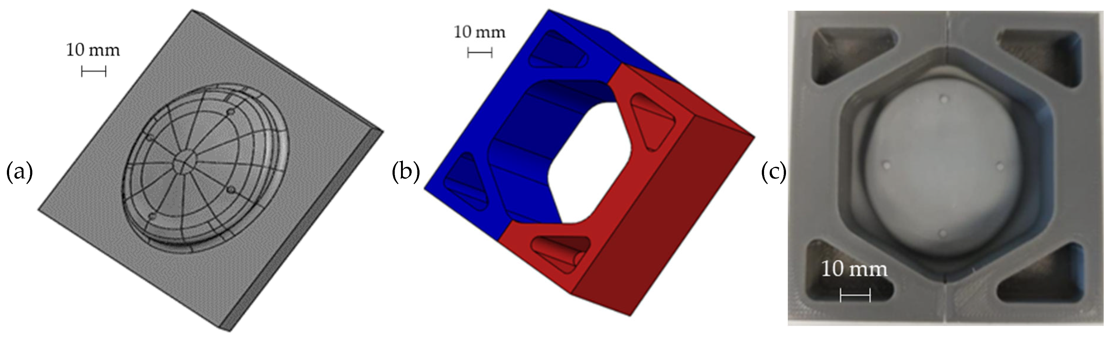
2.3. SPIF Process Design and Prosthesis Manufacturing

During the design of the SPIF process, attention was paid not only to the final geometry of the prosthesis but also to the best positioning of the 3D profile on the flat surface, in order to reduce the blank size and to optimize the final accuracy. The first constraint is represented by the feasibility of the process, then ensuring the forming of the part without excessive thinning while minimizing the material’s waste.
The possibility to obtain the prosthesis geometry by SPIF requires the construction of a sidewall with a shape generally conical: to deform the sheet incrementally without any fracture occurrence, a vertical wall should be avoided. On the contrary, a small inclination of the sidewall would generate a lot of waste. Starting from the prosthesis surface reported in Figure 7a, the sidewall inclination and the best positioning of the prosthesis in the forming area were designed with the aid of numerical simulations. In detail, FE simulations were performed modeling the sheet as a deformable body with S4R elements and 5 integration points along the thickness, whereas the tool was modeled as a rigid body.
The tool path was generated with the CAD/CAM software Creo (v7, PTC, Boston, MA, USA). The periphery of the blank was pinned. The contact was modeled as surface-to-surface contact, setting a Coulomb friction coefficient equal to 0.1 between the tool and the sheet. Finally, the numerical problem was solved with the implicit integration scheme. The final geometry of the part produced by SPIF, characterized by an inclined sidewall of 30°, is reported in Figure 7b.
The above-described geometry was obtained using a hemispherical head tool (diameter: 6 mm) and setting a step depth of 0.05 mm in the CAD/ CAM software used for generating the toolpath for the CNC machine. Figure 8a shows the CAM simulation results of the SPIF geometry after the forming phase. Once completed the SPIF operation, the drilling of the four holes for the prosthesis anchoring, as well as the cutting of the outer edge, was simulated (as reported in Figure 8b).
To manufacture the prosthesis by SPIF, a Mazak Nexus 410 milling machine (Yamazaki Mazak Corporation, Oguchi, Japan) was equipped with a heating chamber able to heat the blank up to 420 °C during the forming process and to keep it constant for the whole manufacturing phase. A feed rate of 2 m/min and a spindle speed of 600 RPM were used. The final geometry of the prostheses was obtained with the same milling machine by using a milling cutter with a diameter of 4 mm and a drill bit with a diameter of 2 mm to perform the anchoring holes.

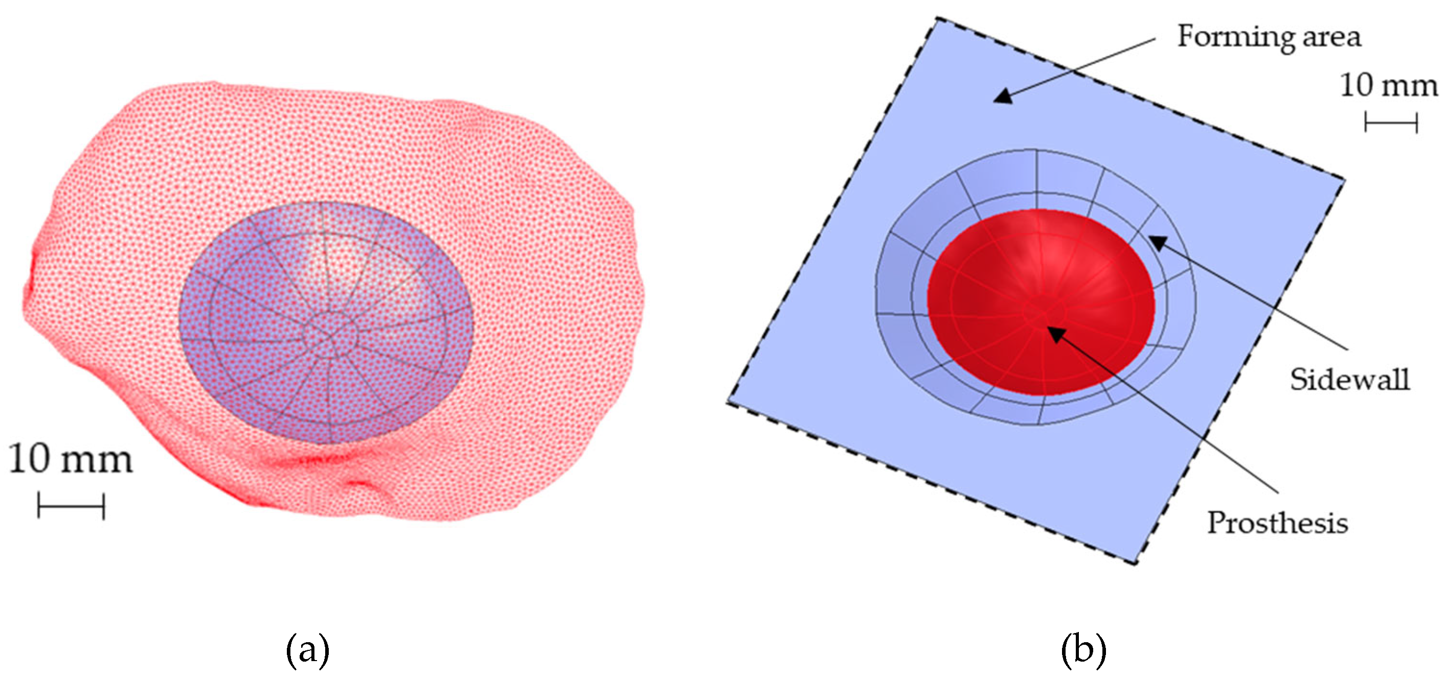
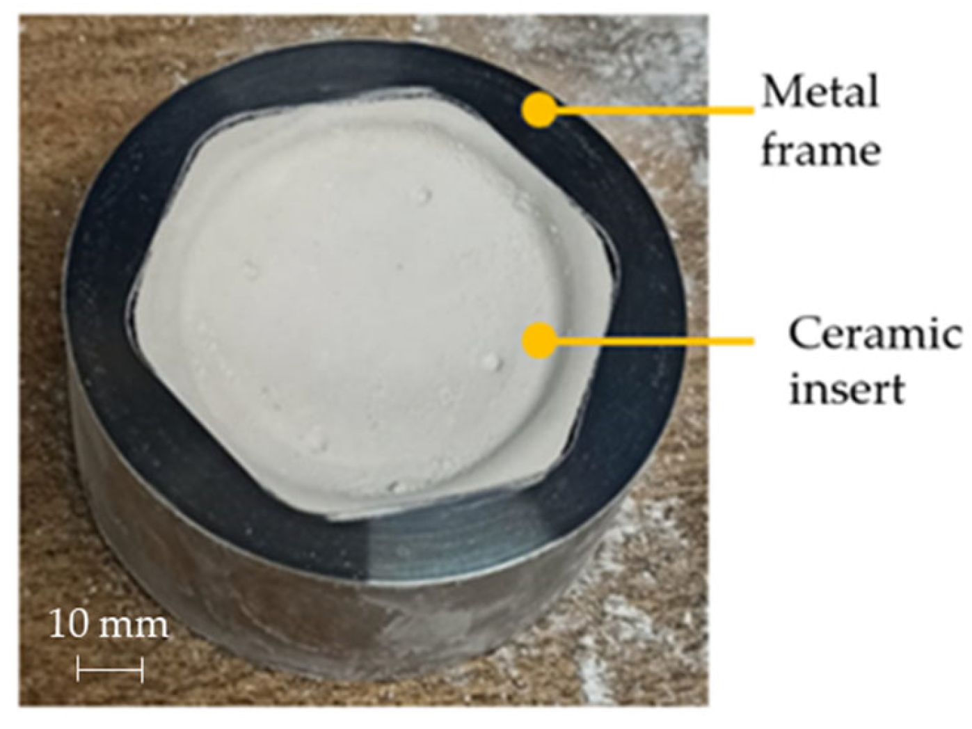
2.4. SPF Process Design and Prosthesis Manufacturing

The optimal conditions (in terms of temperature and strain rate) in which the Ti alloy exhibits the emphasized superplastic behaviour were determined in a previous experimental campaign [15]. The SPF process could be thus designed by means of an FE-based approach implementing the previously evaluated material modelling, with the aim of: (i) defining the geometry of the tool; (ii) calculating the gas pressure profile able to form the blank in the above-mentioned optimal conditions.
Starting from the CAD bone reconstruction (as discussed in Section 2.2), the SPF process was simulated using the commercial software Abaqus. The tool geometry (i.e., the die to be copied by the blank) was modelled using two different approaches, briefly labelled as convex and concave (see Figure 9).
As reported in Figure 9, to obtain the prosthesis geometry (green area), an additional area had to be added to deform the blank and to allow the blankholder action. In addition, 4 protrusions were included in the tool to obtain, on the formed blank, the reference positions to create the anchoring holes. Both the types of the die were modelled as a rigid body, meshing the surface with 1 mm element (R3D3 and R3D4 shell rigid element); the blank was modelled as a shell deformable body using S4R and S3R shell elements (average size equal to 0.5 mm) and considering 5 integration points in the thickness direction. The friction between the die and the blank was modelled using the Coulomb’s formulation and setting the coefficient to 0.1 [20]. The gas pressure profile was calculated by means of an internal subroutine (CREEP STRAIN RATE CONTROL) by specifying that the blank portion in contact with the die surface (the one highlighted in green in Figure 9) had to be deformed under a strain rate target level of 5 × 10⁻⁴ 1/s.
As concerns the prostheses manufacturing, an INSTRON 4485 universal testing machine (INSTRON, Norwood, MA, USA) controlled by a ZwickRoell software (version, ZwickRoell, Ulm, Germany) and equipped with a specifically designed equipment was used. The experimental set-up is composed of a load cell, which allows to control the Blank Holder Force (BHF) during the tests, an upper tool which applies the BHF, and which is connected to the pneumatic circuit for the argon supply, a lower tool and the die. The tools and the die are embedded into an electric split furnace. The starting blank was a 1 mm thickness sheet with a circular shape having a radius of 75 mm. In order to simplify the extraction of the sheet after the forming process, a thin layer of graphite was applied on the external part of the sheet (the one in contact with the blankholder). The temperature of the furnace was set at 850 °C. After the target temperature was reached in the forming chamber, the blank was placed between the tool and the die, and a BHF of 22 kN was applied. Then, the argon gas was inflated into the forming chamber according to the pressure profile calculated by the FE simulations, while the BHF was kept constant by the control system for the whole forming time. As forming tool, a specific ceramic insert placed into a cylindrical steel frame, was used for each prosthesis (customized to the specific anatomy); such a ceramic was manufactured by investment casting using the pattern shown in Figure 10a (created by stereolithography) having the negative geometry of the ceramic insert.
The mould for pouring the ceramic material (Figure 10b) was obtained by Fused Deposition and was assembled putting it on the pattern, as shown in Figure 10c. The mould is composed of two parts (as highlighted by the different colours) in order to simplify the extraction of the ceramic insert after the casting and autoclave curing operations.

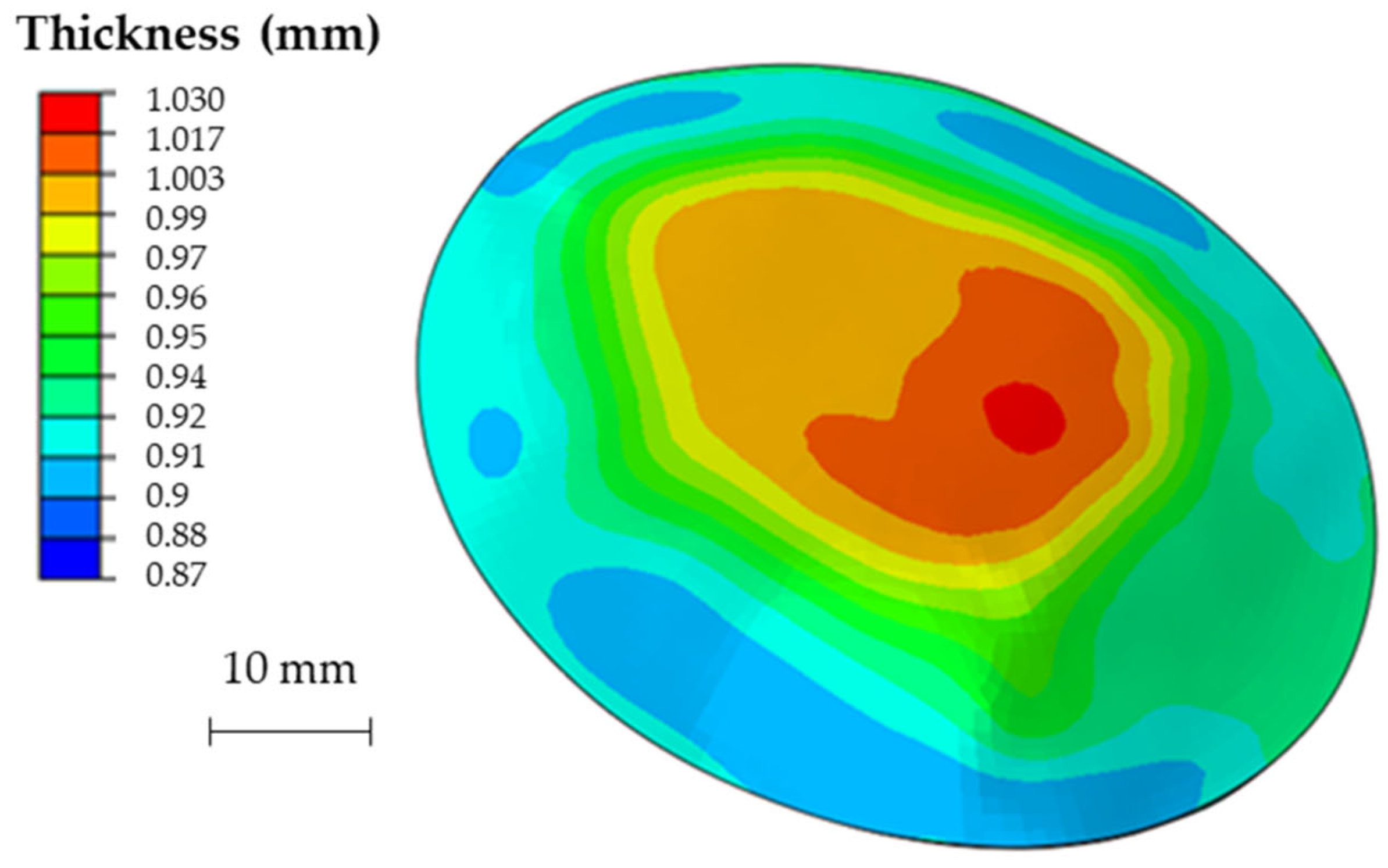
2.5. Post-Forming Analyses

The post-forming analyses were aimed to evaluate the thickness distribution and the shape accuracy of the produced implants. For this purpose, a high-resolution 3D scanner was adopted and the acquisition was manipulated with the GOM Inspect Suite to reduce the noise. In order to evaluate the accuracy and the replicability of the investigated processes, 3 replications of the same prosthesis geometry were manufactured by SPF and by SPIF. Each replication was scanned with the high-resolution 3D scanner and compared with the corresponding skull geometry resulting from the DICOM image to evaluate the shape accuracy. In addition, the replications were also compared to each other in order to evaluate the variability of the process.

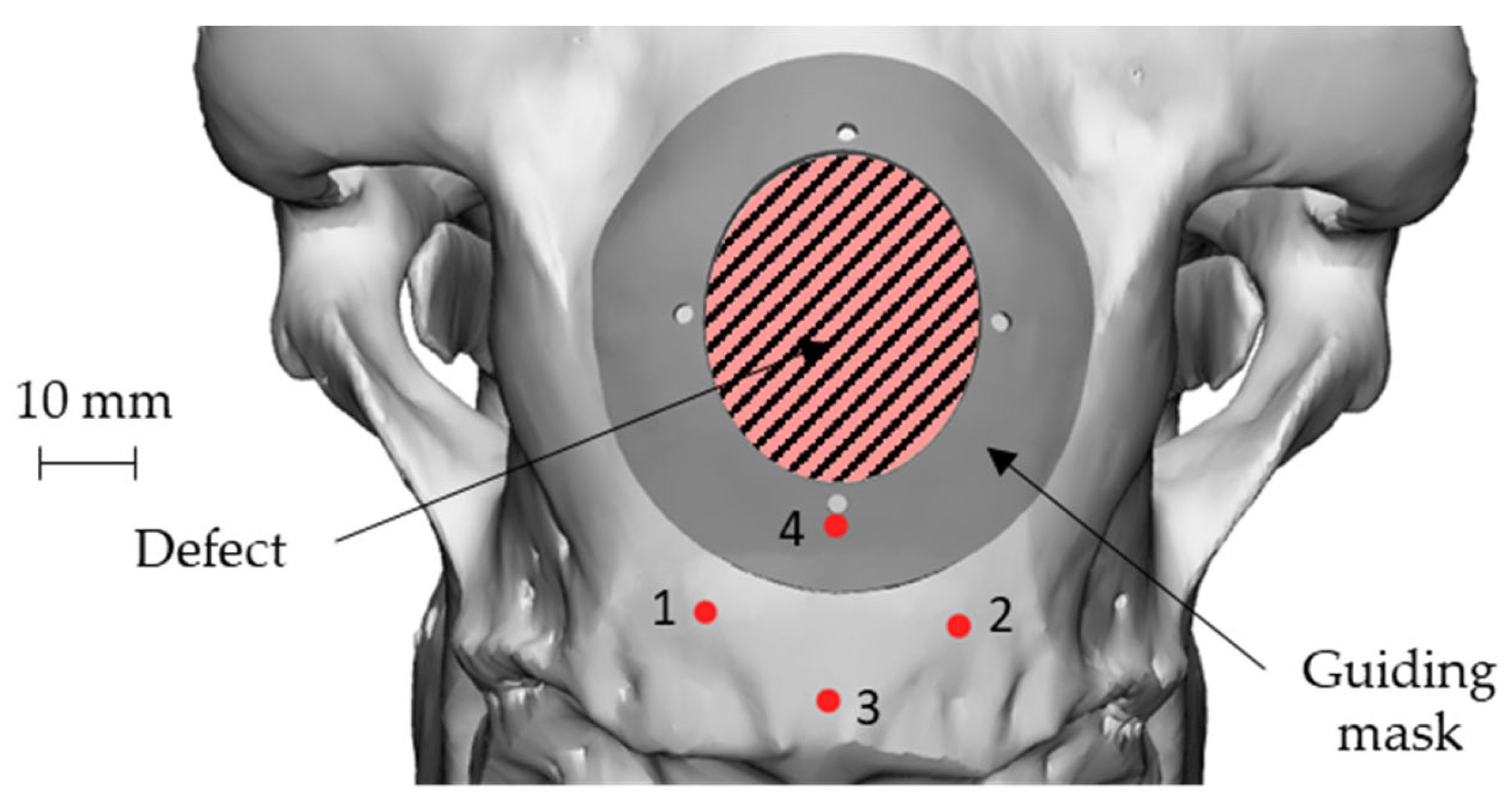
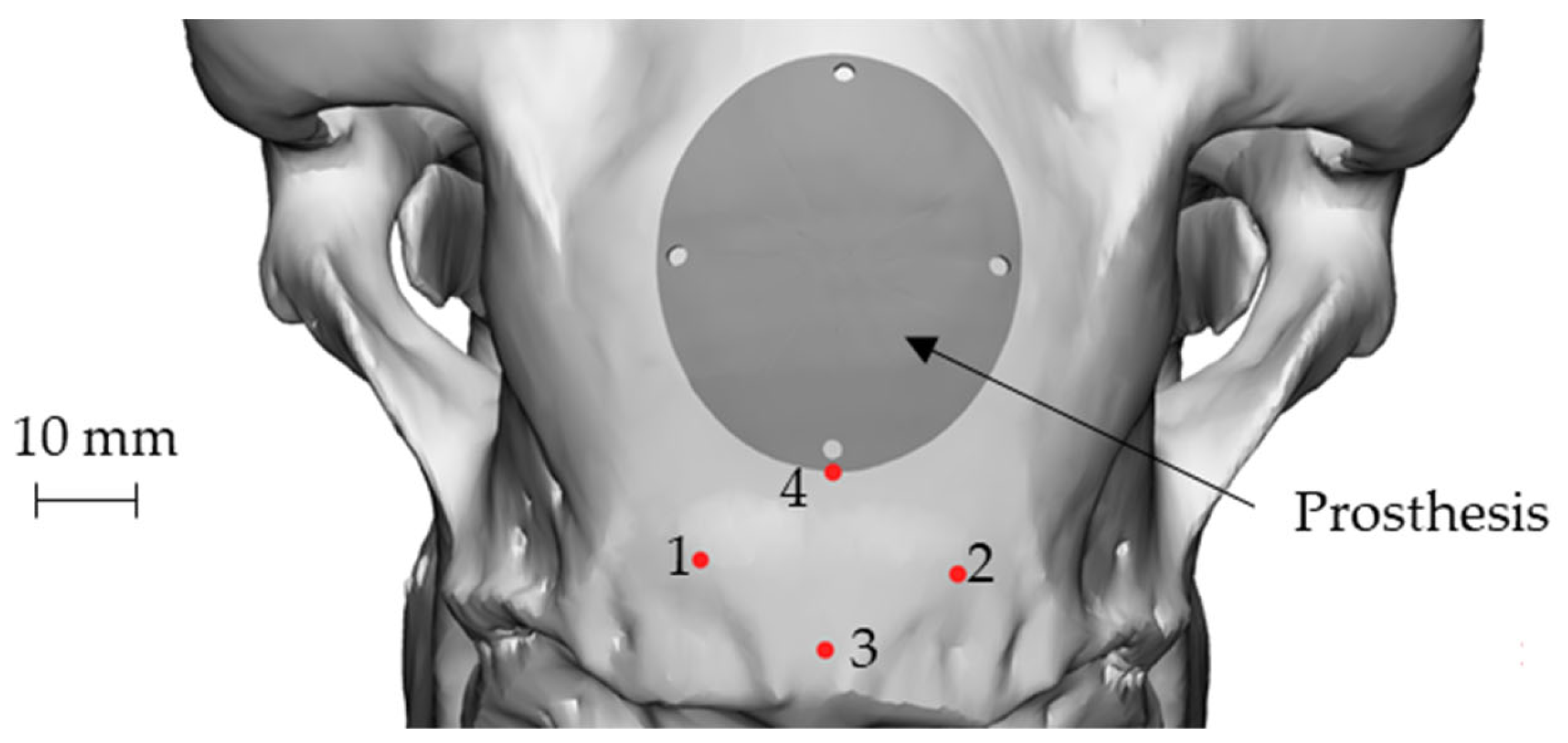
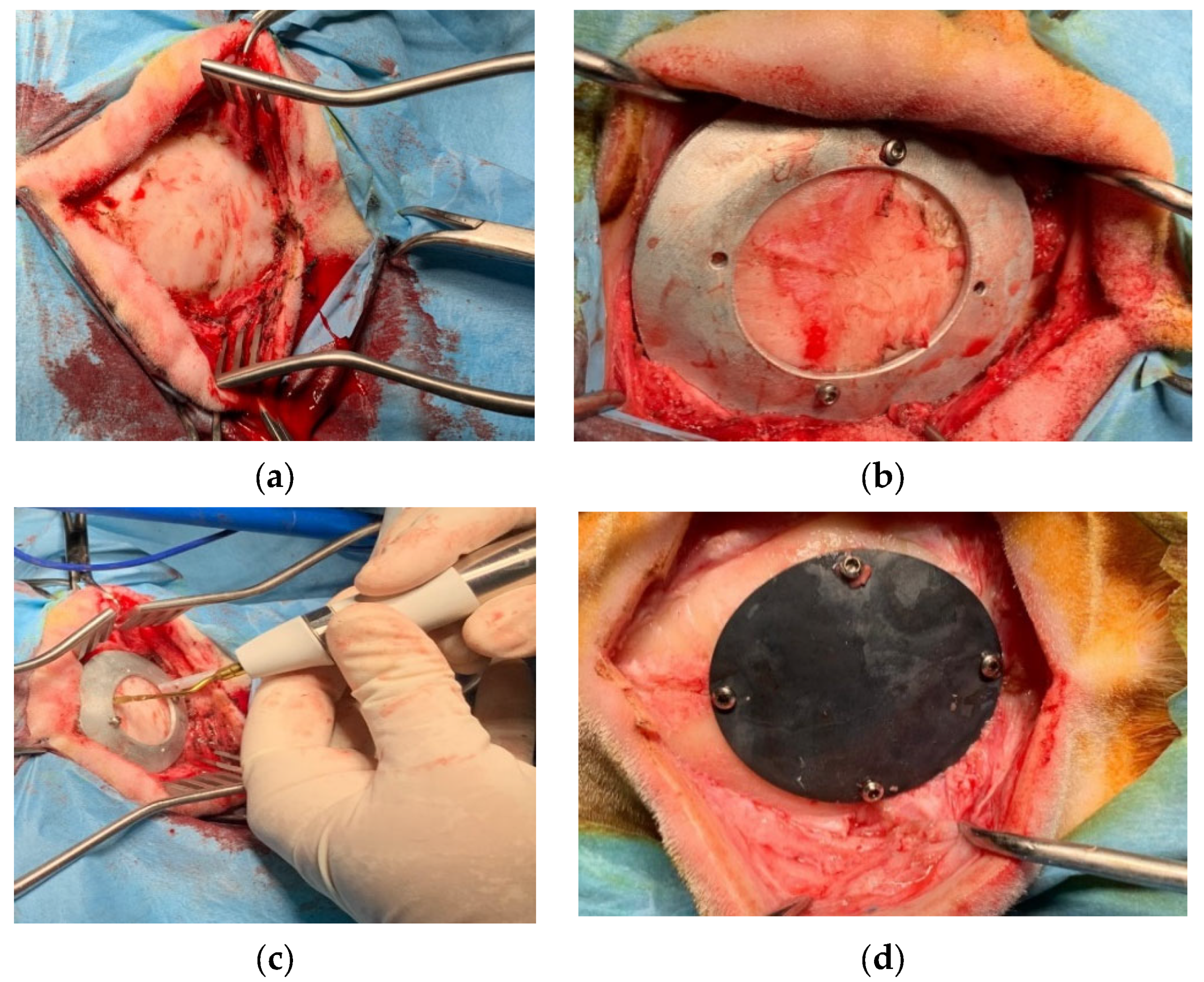
2.6. Implant Surgery

The in vivo study was performed at the facility of the Department of Emergencies and Organ Transplantation of the University of Bari. After the approval of the Italian Minister of Health (Approval number 654/2020 PR), 16 sheep underwent the implantation, in a blind matter, of the two kinds of prothesis. Sheep were divided in two groups: the first one that was sacrificed after 6 months from surgery and the second one after 3 months. As far as the surgery is concerned, an incision was performed at the level of the parietal bone on the skin and subcutaneous tissue (Figure 11a), the custom-made mask was positioned on the bone using screws (Figure 11b) and the ostectomy was performed via piezosurgery (Mectron, Italy) [21] (Figure 11c); the bone gusset and the mask were then removed and the former was replaced with the device that was subsequently anchored using the same holes created for the mask positioning (Figure 11d).
The above tissues were than sutured and the animals were awakened from anaesthesia. After the surgery, depending of the group they belonged to, animals underwent the administration of different bone markers (Tetracycline, Xilenol Orange and Calcein Blue were used for the three months group, whereas Calcein Blue, Tetracyclin Xilenol and Orange and Alizarin Red were used for the six months group). Moreover, the absence of alisteresis and screws and prosthesis mobility, as well as any periprosthetic inflammatory reaction, infections, sub cutaneal exudation and soft tissue scarring times were checked. The sheep’s temperature was also regularly monitored to exclude fever.
After 24 h from the last administration, the animals were euthanized using a propofol overdose, then the heads were removed and were subjected to a CT scan to evaluate the effects of the implant on the bone. The devices were removed using the piezosurgery making a gusset of bone 1 cm from the device on all the sides, then put in formaline for seven days, washed under running water for 24 h and put in 70° ethanol to undergo histological evaluations.

3. Results and Discussion

3.1. SPIF Process Investigation and Outcomes

Since the excessive thinning of the sheet is one of the main drawbacks of the SPIF, the focus of the numerical simulation was kept on the resulting thickness distribution of the formed part. Figure 12 shows the calculated distribution of the section thickness (STH) mapped on the prosthesis at the end of the simulation.
As expected, the minimum thickness is on the outer edge with a minimum value close to 0.9 mm, whereas the maximum thickness is located in the middle zone, being essentially equal to the initial sheet thickness (1 mm). The final geometry of the prostheses obtained by SPIF, after the cutting and drilling operations, is reported in Figure 13a; Figure 13b shows the cleaned prosthesis ready to be implanted.
Figure 14 shows the obtained thickness map on the prosthesis and the corresponding frequency of the thickness values on the whole surface. The maximum and minimum thickness values, as well as their location and distribution, are close to those predicted by the numerical simulation.

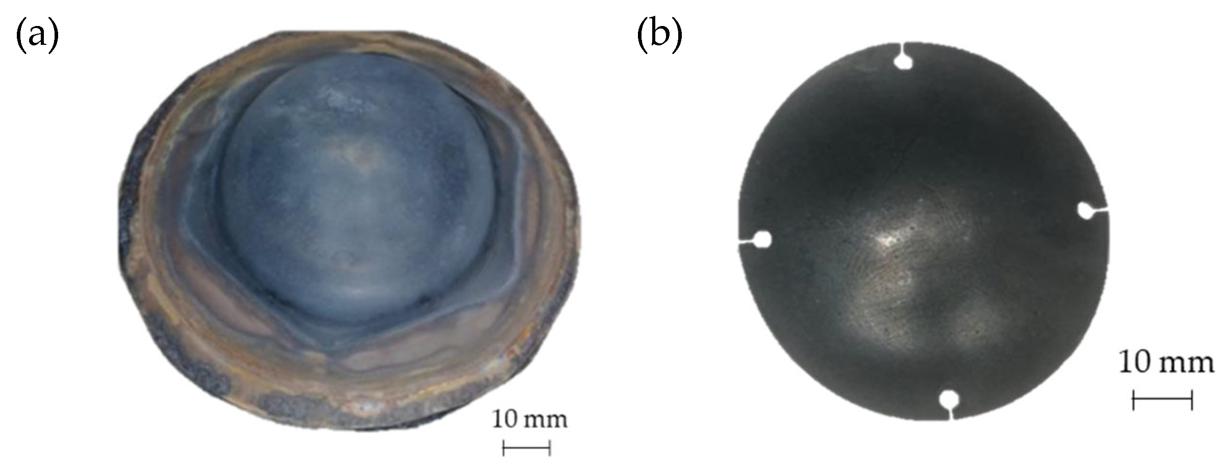
3.2. SPF Process Investigation and Outcomes

The FE simulation of the SPF process allowed to calculate the thickness distributions useful to check the presence of any critical region and to define the gas pressure profile to be used in the manufacturing process. In addition, it was possible to assess the key role played by the die geometry, which resulted to have a significant effect not only on the profile but also on the total forming time, as shown in Figure 15.
The maps showing the distribution of the COPEN output variable are reported for both the investigated types of tools: in fact, such an output variable describes the capability of the blank to fill the die cavity (the blue regions refer to a complete contact between the die and the blank, whereas the white ones indicate that the points are still not adjacent). A consideration that could be drawn from the presented plot is that with both the tools the part corresponding to the final prosthesis geometry was successfully copied; furthermore, by looking at the two pressure profiles, the concave geometry led to a satisfactory filling of the die cavity in a sensibly lower period of time than the other solution. Numerical results were also analysed in terms of final thickness distributions. The curves plotted in Figure 16 suggest that, within the blank portion of the final prosthesis geometry (highlighted by the grey box on each plot), both the investigated tools led to an almost uniform final distribution of thickness along the considered paths, about equal to 0.85 mm.
Due to the large forming time reduction that it allows, the concave die was thus used for the manufacturing of all prostheses. In Figure 17 the customized ceramic insert positioned in the steel frame is shown.
In Figure 18a the geometry of the prosthesis obtained by means of the SPF process is shown, whereas Figure 18b shows the custom prosthesis to be implanted extracted from the formed sheet by wire EDM.
Finally, Figure 19 shows the thickness distribution mapped on the prosthesis obtained via SPF and the corresponding frequency of the thickness values on the whole surface. It is worthy of notice that the prosthesis was characterized by a homogeneous thickness distribution, ranging between 0.91 mm and 0.95 mm.

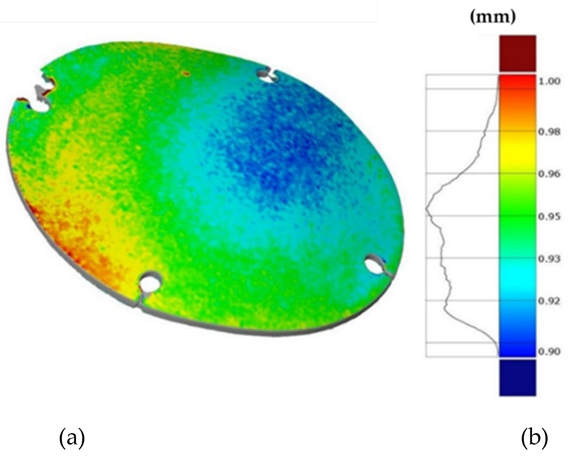
3.3. Shape Accuracy and Replicability

The three replications of the same prosthesis manufactured by both the investigated processes were analysed one to each other and with respect to the initial CAD surface of the skull. Table 2 and Table 3 show the comparison of the scanned data concerning the three replications obtained by SPIF and SPF in terms of average alignment error.
It can be seen that the investigated forming processes are characterized by a low variability, since in both the cases the higher value of the average error between the replications is below 0.01 mm.
At the same time, the SPF process reveals to be able to produce prostheses characterised by higher accuracy (the average error between the deformed geometry and the CAD model is close to zero). However, it should be noted that such a result is determined by the adoption of a female die which, on the contrary, was not necessary for the SPIF process.
It should be also noted that, even without a die, the SPIF process allowed us to obtain a prosthesis characterised by an average error between the deformed geometry and the CAD model very small (about 0.12 mm). The proposed results confirm the effectiveness of the investigated manufacturing processes in ensuring a high dimensional accuracy of the formed blanks: SPIF prostheses’ deviations are comparable to those achieved after the manufacturing of a TA1 cranial implant [22]. Both the investigated processes were accurate, ensuring lower deviations if compared to the accuracy achievable using the same alloy but more conventional [23] or, alternatively, an additive manufacturing approach [24]. The level of correspondence between the formed and the designed geometry is comparable, in the case of the SPIF, or even lower, in the case of the SPF, to the one reported in the literature regarding the manufacturing of PEEK [25] and PMMA [26] customized implants by 3D printing.

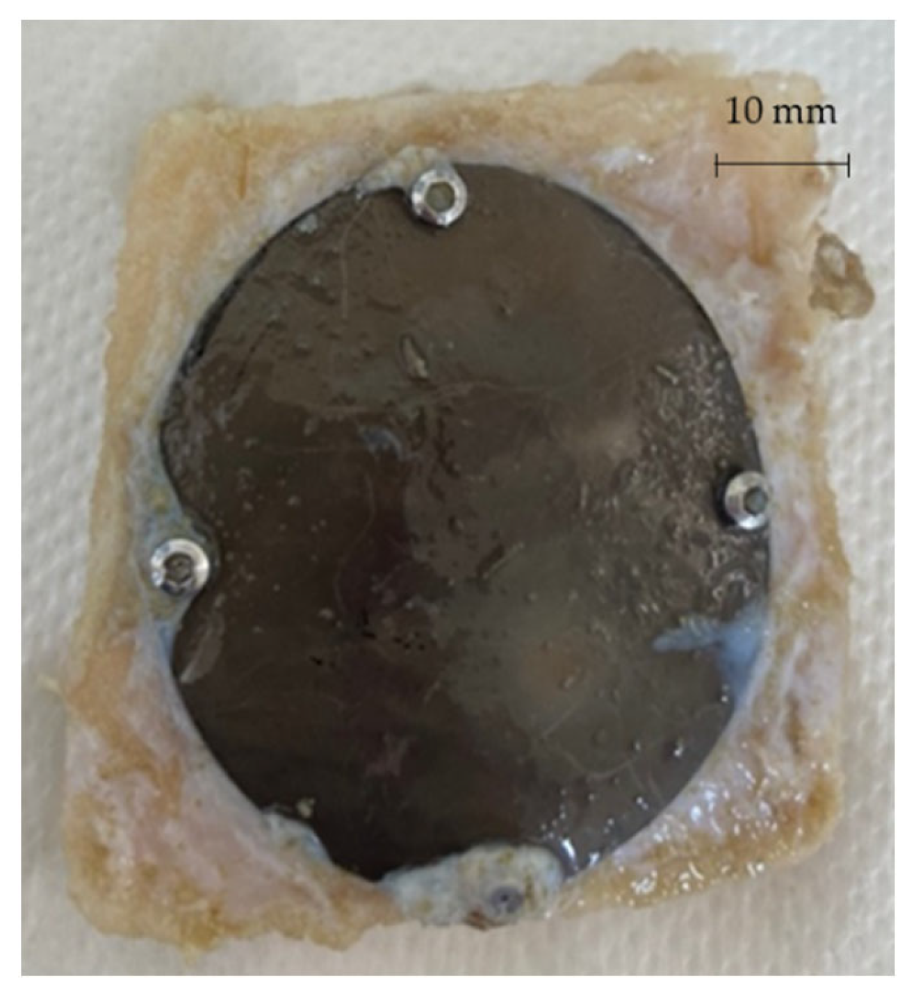
3.4. In Vivo Behaviour of the Prostheses

The adopted procedure for the design of both the prosthesis and the surgery tools (the guiding mask) revealed to be effective since, after the surgery, in all the treated animals there were no side effects noticed in the prothesis area, the reparation of the soft tissue was normal and according to the scarring times; moreover, the body temperature was normal in the post-operative period and all the animals resumed the normal behaviour immediately.
The border of the region that was obtained by the ostectomy was then analysed evaluating the presence of thermal damages on the bone and the presence of damages on the other nervous tissue and the dura madre around the ostectomy area.
Both the types of the implant produced using the two investigated processes resulted to fit suitably the anatomy of the specific animal, thus avoiding any modelling of the prosthesis in the surgery room.
In addition, the implanted prostheses revealed to be much thinner than the ones which could be produced by both standard (machining) and innovative (Additive Manufacturing) production technologies, being at the same time enough resistant.
After 3 and 6 months from the surgery, the sheep were sacrificed and the prostheses extracted in order to be analysed. Figure 20 shows one of the prostheses (from one of the 3 months sacrificed sheep) and the bone gusset removed post mortem.

4. Conclusions

In this study an original methodology based on a coupled mechanical and surgical approach has been proposed. The procedure combines the well assessed prosthesis reconstruction procedures, based on the conversion of DICOM imagine into CAD model, thus ensuring the proper definition of the implant geometry. The manufacturing of an innovative guiding mask can be regarded as an innovative step to ensure the correct and replicable positioning of the implant during the surgery, thus minimizing any mismatch with the per-implant bone. The respect of the bone geometry was then ensured by relying on two innovative and flexible manufacturing processes: the scans on the formed blanks demonstrated not only a high level of the geometry replicability (few hundredths of mm) but also very low deviations from the designed CAD geometry, even lower than what is achievable with alternative manufacturing approaches.
The effectiveness of the design and manufacturing chain, applied to the case study of a customized prosthesis for sheep, was finally evaluated carrying out the in vivo tests. The absence of any side effect (as evidence of the high mechanical fixation of the prosthesis on the surrounding bones) demonstrates that the full application of this methodology ensures both high accuracy and significant replicability of the results, validating the effectiveness of the whole approach.

Author Contributions

Formal analysis: A.C. (Alberto Crovace), A.P., A.C. (Angela Cusanno), P.G., L.D.N. and G.S.; Funding acquisition: G.P. and G.A.; Investigation: A.P., A.C. (Angela Cusanno), P.G., A.C. (Alberto Crovace) and G.S.; Methodology: G.P. and G.A.; Supervision: G.P.; Writing—original draft: A.P., A.C. (Angela Cusanno), P.G. and G.S.; Writing—review & editing: G.P. and G.A. All authors have read and agreed to the published version of the manuscript.

Funding

This research was funded by the Italian Ministry of University and Research through the call Proof of Concept 2018 (acronym: FORMAE-BIO), grant number POC01_00097.

Institutional Review Board Statement

The study was conducted according to the guidelines of the Declaration of Helsinki, and approved by the Ethics Committee (protocol code 654/2020 PR).

Informed Consent Statement

Not applicable.

Data Availability Statement

Not applicable.

Acknowledgments

The authors wish to thank Tomaso Villa for his contribution in acquiring the funds.

Conflicts of Interest

The authors declare no conflict of interest; the funders had no role in the design of the study; in the collection, analyses, or interpretation of data; in the writing of the manuscript, or in the decision to publish the results.

References

  1. Castelan, J.; Schaeffer, L.; Daleffe, A.; Fritzen, D.; Salvaro, V.; Da Silva, F.P. Manufacture of custom-made cranial implants from DICOM® images using 3D printing, CAD/CAM technology and incremental sheet forming. Rev. Bras. Eng. Biomed. 2014, 30, 265–273. [Google Scholar] [CrossRef] [Green Version]
  2. Mallya, P.K.; Juneja, M. Rapid prototyping of orthopedic implant materials for cranio-facial reconstruction: A survey. Mater. Today Proc. 2021, 45, 5207–5213. [Google Scholar] [CrossRef]
  3. Saldarriaga Design and Manufacturing of a Custom Skull Implant. Am. J. Eng. Appl. Sci. 2011, 4, 169–174. [CrossRef] [Green Version]
  4. Mohammed, M.I.; Tatineni, J.; Cadd, B.; Peart, G.; Gibson, I. Advanced auricular prosthesis development by 3D modelling and multi-material printing. KnE Eng. 2017, 2, 37. [Google Scholar] [CrossRef]
  5. Tanveer, W.; Ridwan-Pramana, A.; Molinero-Mourelle, P.; Koolstra, J.H.; Forouzanfar, T. Systematic review of clinical applications of cad/cam technology for craniofacial implants placement and manufacturing of nasal prostheses. Int. J. Environ. Res. Public Health 2021, 18, 3756. [Google Scholar] [CrossRef]
  6. Kiradzhiyska, D.D.; Mantcheva, R.D. Overview of Biocompatible Materials and Their Use in Medicine. Folia Med. (Plovdiv). 2019, 61, 34–40. [Google Scholar] [CrossRef]
  7. Cai, D.; Zhao, X.; Yang, L.; Wang, R.; Qin, G.; Chen, D.F.; Zhang, E. A novel biomedical titanium alloy with high antibacterial property and low elastic modulus. J. Mater. Sci. Technol. 2021, 81, 13–25. [Google Scholar] [CrossRef]
  8. Jackson, M. Superplastic Forming of Advanced Metallic Materials; Elsevier: Amsterdam, The Netherlands, 2011; ISBN 9781845697532. [Google Scholar]
  9. Disegi, J.A. Titanium alloys for fracture fixation implants. Injury 2000, 31 (Suppl. S4), 14–17. [Google Scholar] [CrossRef]
  10. Wazen, R.M.; Currey, J.A.; Guo, H.; Brunski, J.B.; Helms, J.A.; Nanci, A. Micromotion-induced strain fields influence early stages of repair at bone-implant interfaces. Acta Biomater. 2013, 9, 6663–6674. [Google Scholar] [CrossRef] [Green Version]
  11. Piccininni, A.; Gagliardi, F.; Guglielmi, P.; De Napoli, L.; Ambrogio, G.; Sorgente, D.; Palumbo, G. Biomedical Titanium alloy prostheses manufacturing by means of Superplastic and Incremental Forming processes. In MATEC Web of Conferences; EDP Sciences: Les Ulis, France, 2016; Volume 80. [Google Scholar]
  12. Cheng, Z.; Li, Y.; Xu, C.; Liu, Y.; Ghafoor, S.; Li, F. Incremental sheet forming towards biomedical implants: A review. J. Mater. Res. Technol. 2020, 9, 7225–7251. [Google Scholar] [CrossRef]
  13. Limited, W.P. Processing and machining of aerospace metals. Introd. Aerosp. Mater. 2012, 154–172. [Google Scholar] [CrossRef]
  14. Mosleh, A.O.; Mikhaylovskaya, A.V.; Kotov, A.D.; Kwame, J.S. Experimental, modelling and simulation of an approach for optimizing the superplastic forming of Ti-6%Al-4%V titanium alloy. J. Manuf. Process. 2019, 45, 262–272. [Google Scholar] [CrossRef]
  15. Sorgente, D.; Palumbo, G.; Piccininni, A.; Guglielmi, P.; Aksenov, S.A. Investigation on the thickness distribution of highly customized titanium biomedical implants manufactured by superplastic forming. CIRP J. Manuf. Sci. Technol. 2018, 20, 29–35. [Google Scholar] [CrossRef]
  16. Guglielmi, P.; Cusanno, A.; Bagudanch, I.; Centeno, G.; Ferrer, I.; Garcia-Romeu, M.L.; Palumbo, G. Experimental and numerical analysis of innovative processes for producing a resorbable cheekbone prosthesis. J. Manuf. Process. 2021, 70, 1–14. [Google Scholar] [CrossRef]
  17. Ambrogio, G.; Gagliardi, F.; Chamanfar, A.; Misiolek, W.Z.; Filice, L. Induction heating and cryogenic cooling in single point incremental forming of Ti-6Al-4V: Process setup and evolution of microstructure and mechanical properties. Int. J. Adv. Manuf. Technol. 2017, 91, 803–812. [Google Scholar] [CrossRef]
  18. Filice, L.; Ambrogio, G.; Gaudioso, M. Optimised tool-path design to reduce thinning in incremental sheet forming process. Int. J. Mater. Form. 2013, 6, 173–178. [Google Scholar] [CrossRef]
  19. Ambrogio, G.; Palumbo, G.; Sgambitterra, E.; Guglielmi, P.; Piccininni, A.; De Napoli, L.; Villa, T.; Fragomeni, G. Experimental investigation of the mechanical performances of titanium cranial prostheses manufactured by super plastic forming and single-point incremental forming. Int. J. Adv. Manuf. Technol. 2018, 98, 1489–1503. [Google Scholar] [CrossRef]
  20. Sorgente, D.; Palumbo, G.; Piccininni, A.; Guglielmi, P.; Tricarico, L. Modelling the superplastic behaviour of the Ti6Al4V-ELI by means of a numerical/experimental approach. Int. J. Adv. Manuf. Technol. 2017, 90, 1–10. [Google Scholar] [CrossRef]
  21. Crovace, A.M.; Luzzi, S.; Lacitignola, L.; Fatone, G.; Lucifero, A.G.; Vercellotti, T.; Crovace, A. Minimal invasive piezoelectric osteotomy in neurosurgery: Technic, applications, and clinical outcomes of a retrospective case series. Vet. Sci. 2020, 7, 68. [Google Scholar] [CrossRef]
  22. Lu, B.; Ou, H.; Shi, S.Q.; Long, H.; Chen, J. Titanium based cranial reconstruction using incremental sheet forming. Int. J. Mater. Form. 2016, 9, 361–370. [Google Scholar] [CrossRef] [Green Version]
  23. Peel, S.; Eggbeer, D.; Burton, H.; Hanson, H.; Evans, P.L. Additively manufactured versus conventionally pressed cranioplasty implants: An accuracy comparison. Proc. Inst. Mech. Eng. Part H J. Eng. Med. 2018, 232, 949–961. [Google Scholar] [CrossRef] [PubMed]
  24. Moiduddin, K.; Mian, S.H.; Umer, U.; Alkhalefah, H. Fabrication and analysis of a Ti6Al4V implant for cranial restoration. Appl. Sci. 2019, 9, 2513. [Google Scholar] [CrossRef] [Green Version]
  25. Berretta, S.; Evans, K.; Ghita, O. Additive manufacture of PEEK cranial implants: Manufacturing considerations versus accuracy and mechanical performance. Mater. Des. 2018, 139, 141–152. [Google Scholar] [CrossRef]
  26. Chamo, D.; Msallem, B.; Sharma, N.; Aghlmandi, S.; Kunz, C.; Thieringer, F.M. Accuracy assessment of molded, patient-specific polymethylmethacrylate craniofacial implants compared to their 3D printed originals. J. Clin. Med. 2020, 9, 832. [Google Scholar] [CrossRef] [PubMed] [Green Version]
Figure 1. Schematic overview of the complete procedure for designing and producing titanium cranial prostheses.
Metals 12 00293 g001
Figure 2. Schematic overview of the imported DICOM files and the resulting 3D skull volume reconstruction: (a) axial slice, (b) sagittal slice, (c) coronal slice and (d) 3D volume.
Metals 12 00293 g002
Figure 3. Position of the nuchal tendon attachment points on the skull, the 4 landmarks and representation of both the defect and the prosthetic geometry: attachment of the nuchal tendons (points 1 and 2), sagittal plane (points 3 and 4).
Metals 12 00293 g003
Figure 4. (a) Lateral view and (b) top view of the reconstructed analytical surface of the ROI and the original portion of the skull (red mesh) including the ROI.
Metals 12 00293 g004
Figure 5. Geometry and positioning of the guiding mask on the skull with respect to the 4 landmarks and to the defect geometry: attachment of the nuchal tendons (points 1 and 2), sagittal plane (points 3 and 4).
Metals 12 00293 g005
Figure 6. The final geometry of the prosthesis placed on the skull: attachment of the nuchal tendons (points 1 and 2), sagittal plane (points 3 and 4).
Metals 12 00293 g006
Figure 7. (a) The reconstructed analytical surface of the ROI and the original portion of the skull (red mesh) near the ROI, (b) the designed final geometry for the SPIF.
Metals 12 00293 g007
Figure 8. (a) CAM simulation results of the SPIF geometry after the forming phase; (b) final prosthesis after the CNC milling simulation.
Metals 12 00293 g008
Figure 9. Different types of dies used for the SPF simulation: (a) convex and (b) concave.
Metals 12 00293 g009
Figure 10. CAD model of (a) the photopolymeric base and (b) the upper bracket of the mould used for manufacturing the ceramic insert for the die; (c) assembled mould.
Metals 12 00293 g010
Figure 11. Surgical procedure for the in vivo studies: (a) exteriorizing of parietal bone; (b) guiding mask fixed to the bone with screws; (c) bone gusset removal through piezosurgery osteotomy; (d) device implantation and fixation with screws.
Metals 12 00293 g011
Figure 12. Numerical thickness map resulting from the FEM analysis of the SPIF process (dimensions: mm).
Metals 12 00293 g012
Figure 13. (a) Prosthesis after the SPIF manufacturing, cutting and drilling operations; (b) final prosthesis obtained by SPIF after cleaning operations.
Metals 12 00293 g013
Figure 14. (a) Thickness map of the prosthesis produced by SPIF and (b) frequency of the thickness values.
Metals 12 00293 g014
Figure 15. Gas pressure profiles obtained from the simulations of the SPF process when using the two investigated types of tools.
Metals 12 00293 g015
Figure 16. Thickness distributions along: (a) the longitudinal and (b) transversal symmetry paths.
Metals 12 00293 g016
Figure 17. Die adopted during the prostheses manufacturing via SPF.
Metals 12 00293 g017
Figure 18. (a) Prostheses manufactured via SPF; (b) final geometry obtained after EDM cutting.
Metals 12 00293 g018
Figure 19. (a) Thickness map of the prosthesis produced by SPF; (b) frequency of thickness values.
Metals 12 00293 g019
Figure 20. Prosthesis and bone gusset removed post mortem.
Metals 12 00293 g020
Table 1. Chemical composition of the investigated Ti alloys.
ElementAl%V%Fe%C%N%H%O%Ti
value5.883.870.140.220.0060.0020.112Bal.
Table 2. Average error of the three replications obtained by SPIF.
Compared GeometriesAverage Error (mm)Map
SPIF #1 vs. SPIF #20.0150 Metals 12 00293 i001 Metals 12 00293 i002
SPIF #1 vs. SPIF #30.0193 Metals 12 00293 i003
SPIF #2 vs. SPIF #30.0160 Metals 12 00293 i004
SPIF #2 vs. CAD0.1202 Metals 12 00293 i005 Metals 12 00293 i006
Table 3. Average error of the three SPF replications.
Compared GeometriesAverage Error (mm)Map
SPF #1 vs. SPF #20.0141 Metals 12 00293 i007 Metals 12 00293 i008
SPF #1 vs. SPF #30.0112 Metals 12 00293 i009
SPF #2 vs. SPF #30.0115 Metals 12 00293 i010
SPF #2 vs. CAD0.0205 Metals 12 00293 i011 Metals 12 00293 i012
Publisher’s Note: MDPI stays neutral with regard to jurisdictional claims in published maps and institutional affiliations.

