
The Performance of 3D Printed Polymer Tools in Sheet Metal Forming


Abstract
:1. Introduction
2. Materials and Methods
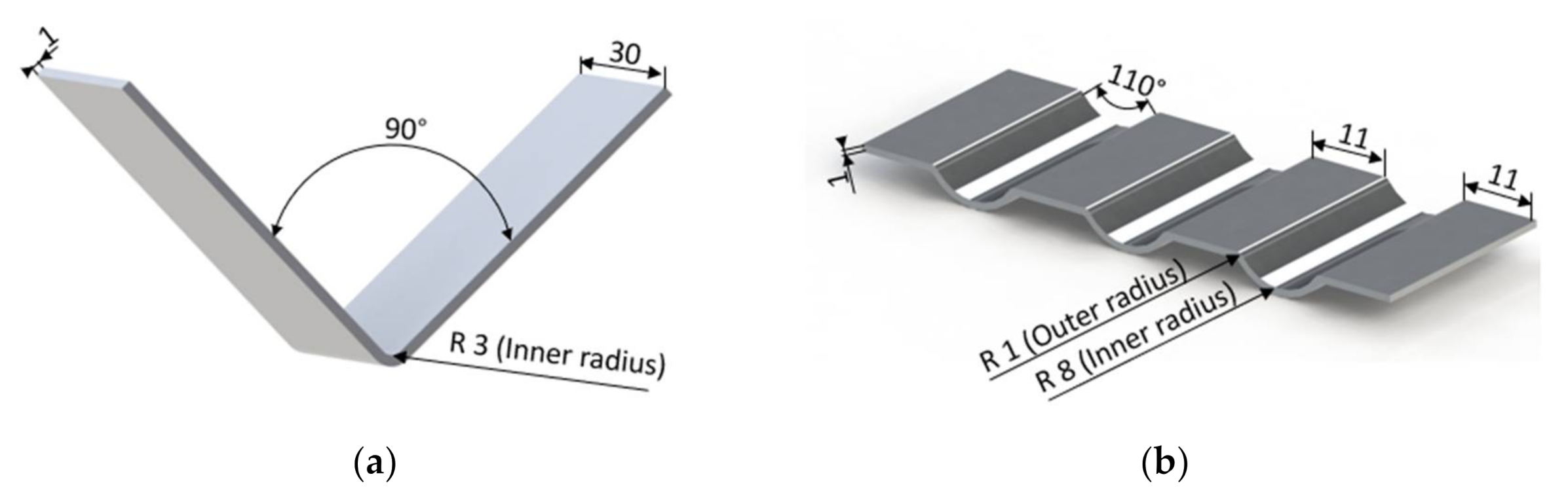
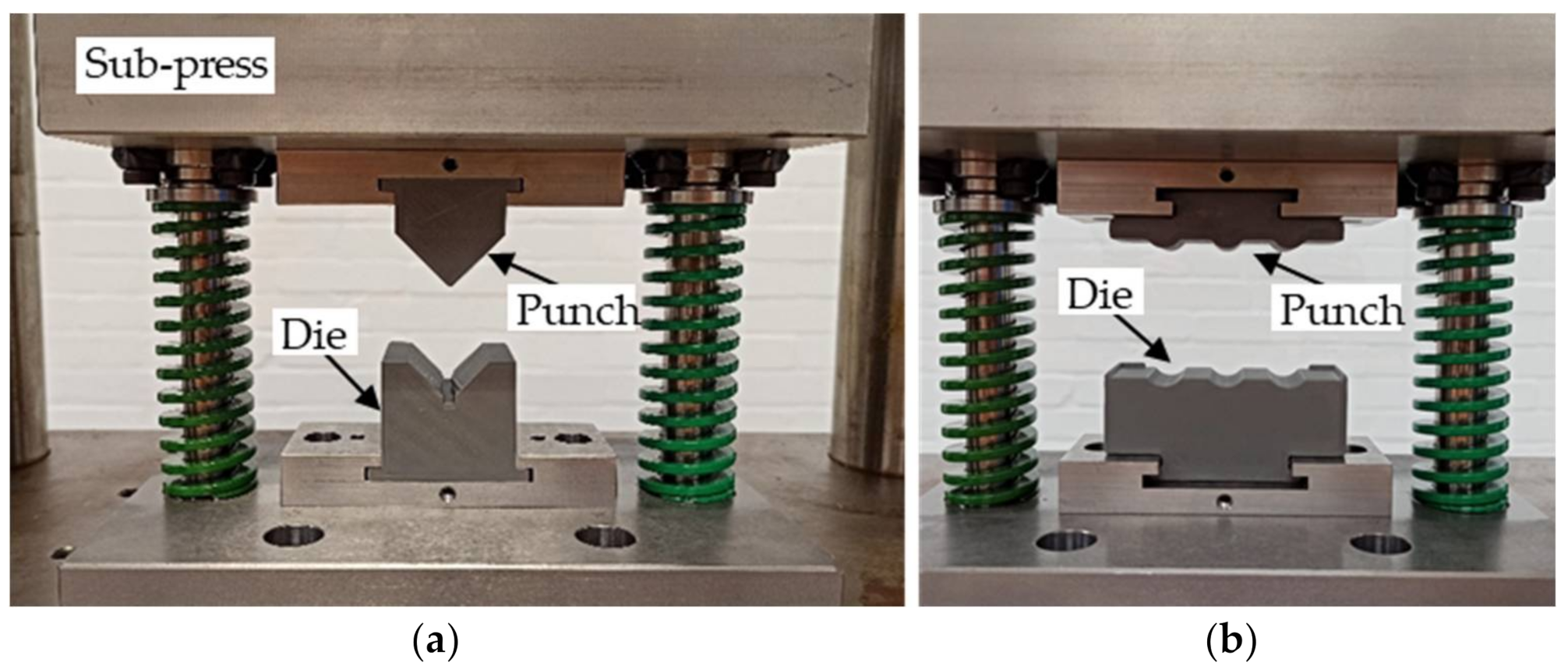
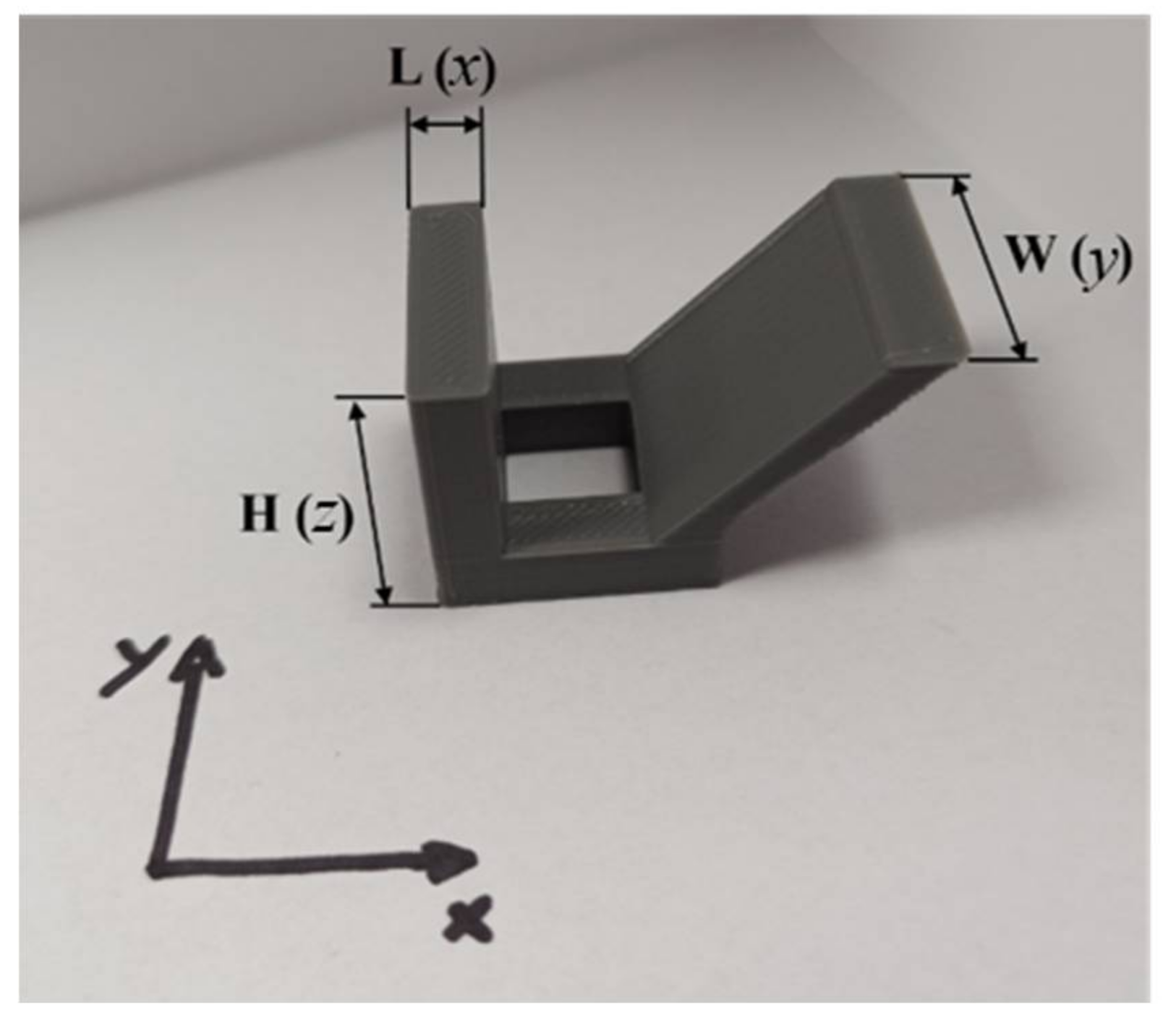
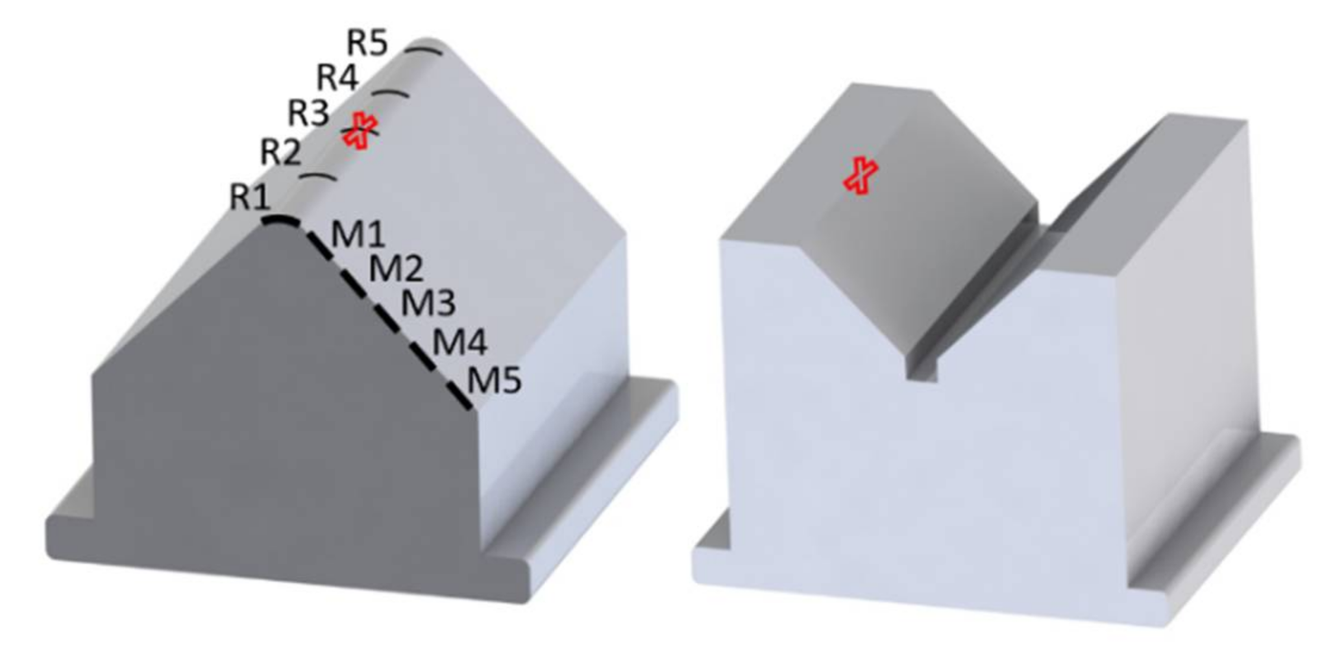
2.1. Equipment and Evaluation Geometries
2.2. Printing Material and Strategy
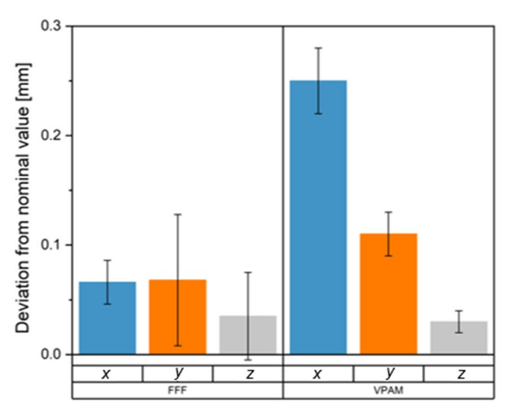
2.3. Precision, Accuracy and Surface Roughness of the Printed Parts
2.4. Measurement Procedures and Strategy
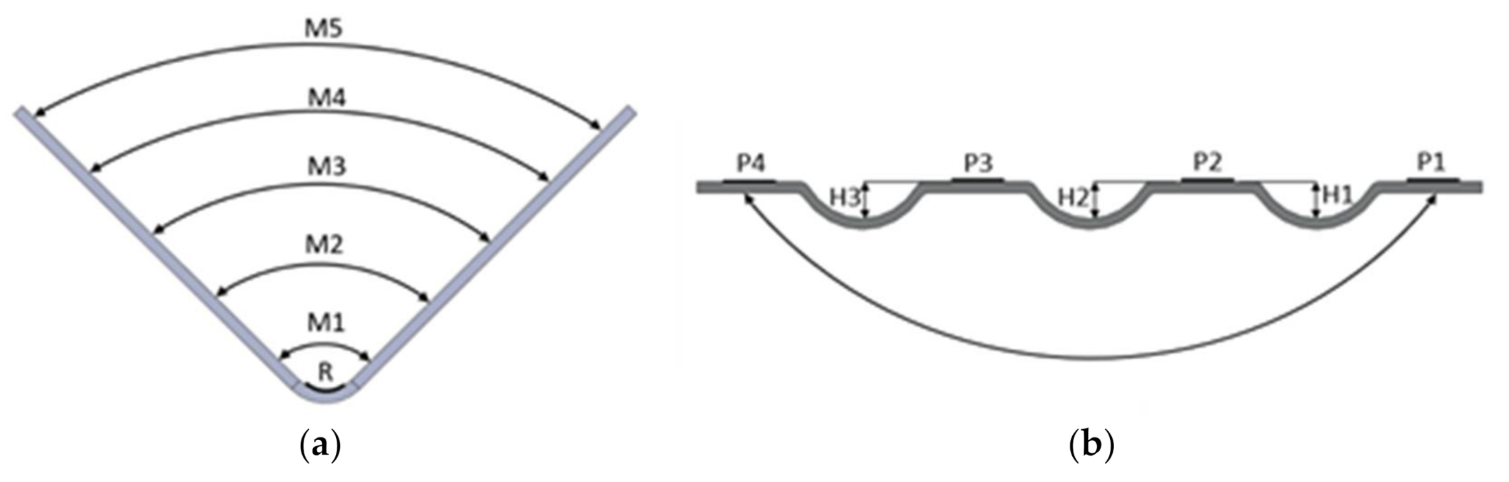
3. Accuracy and Wear in V-Bending
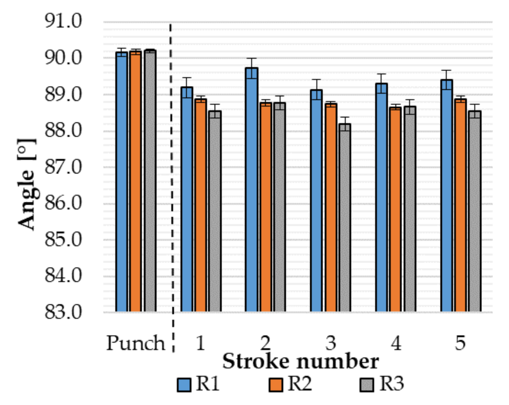
3.1. Change in Tool Geometry and Surface vs. Number of Strokes
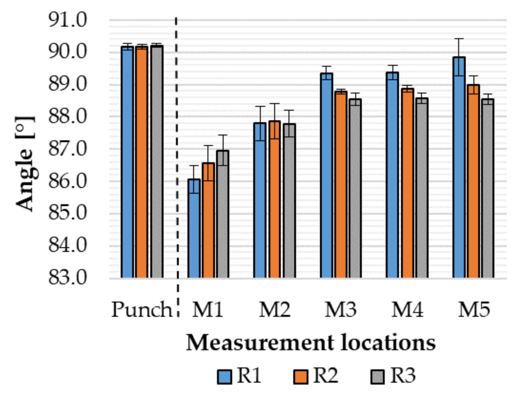
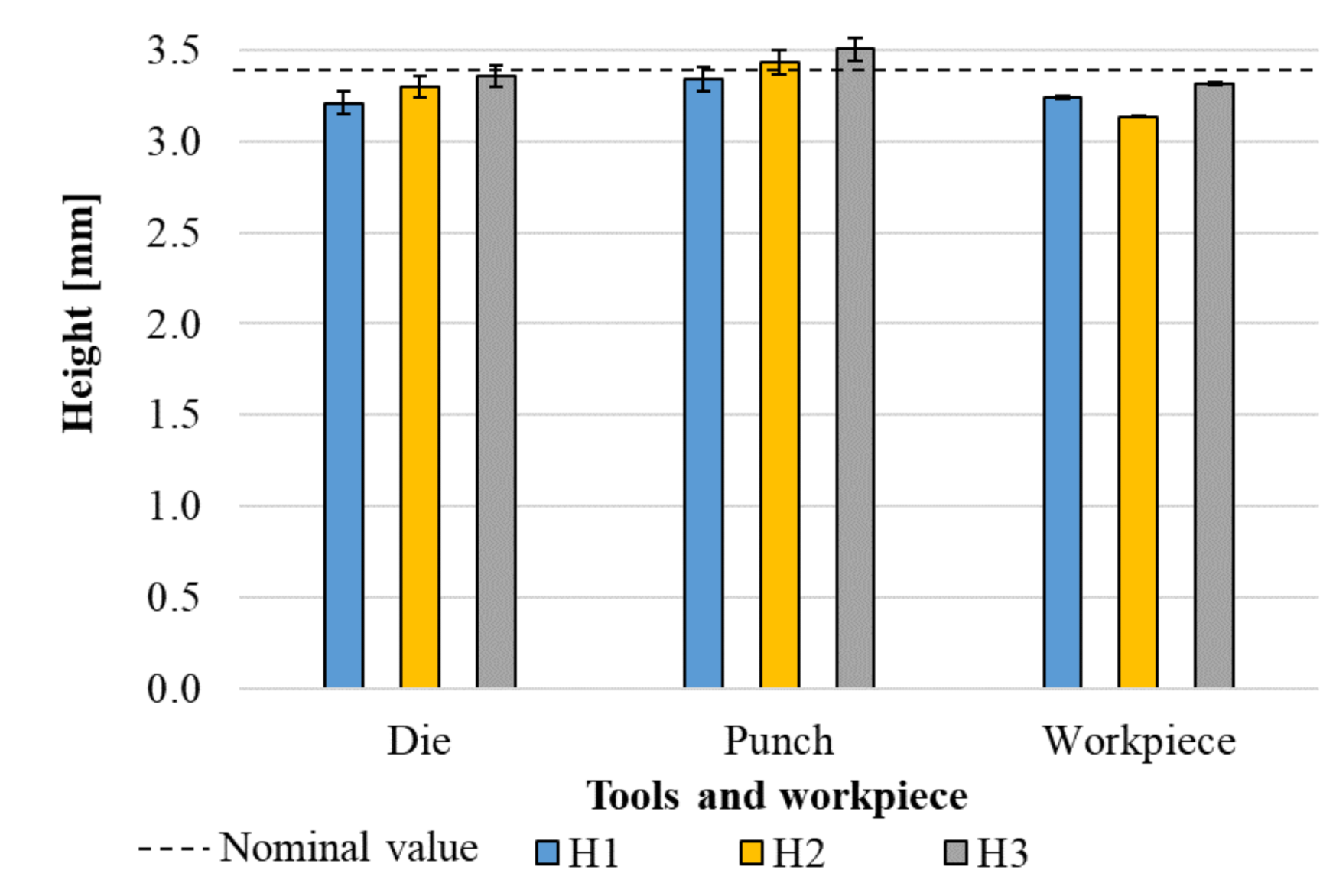
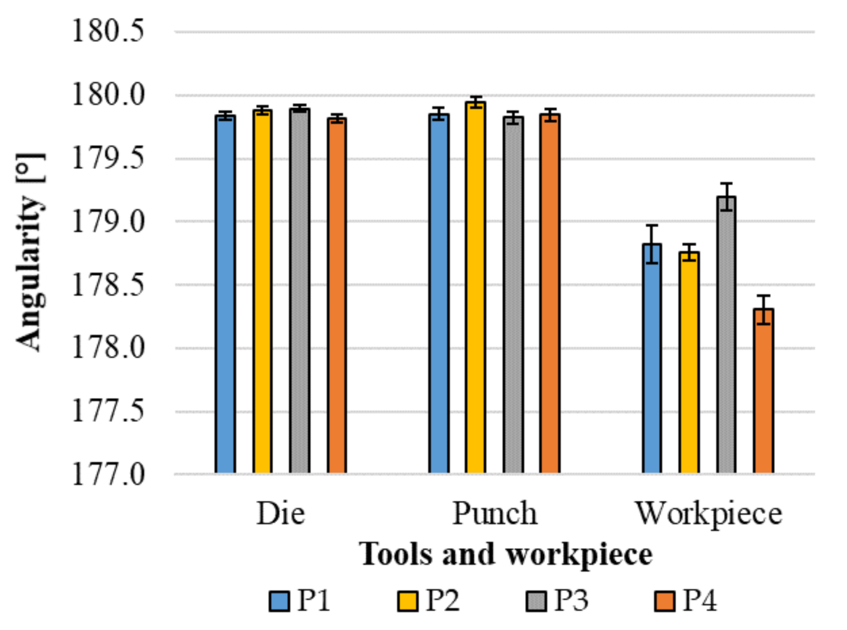
3.2. Springback, Geometrical Accuracy and Comparison to Tool Accuracy
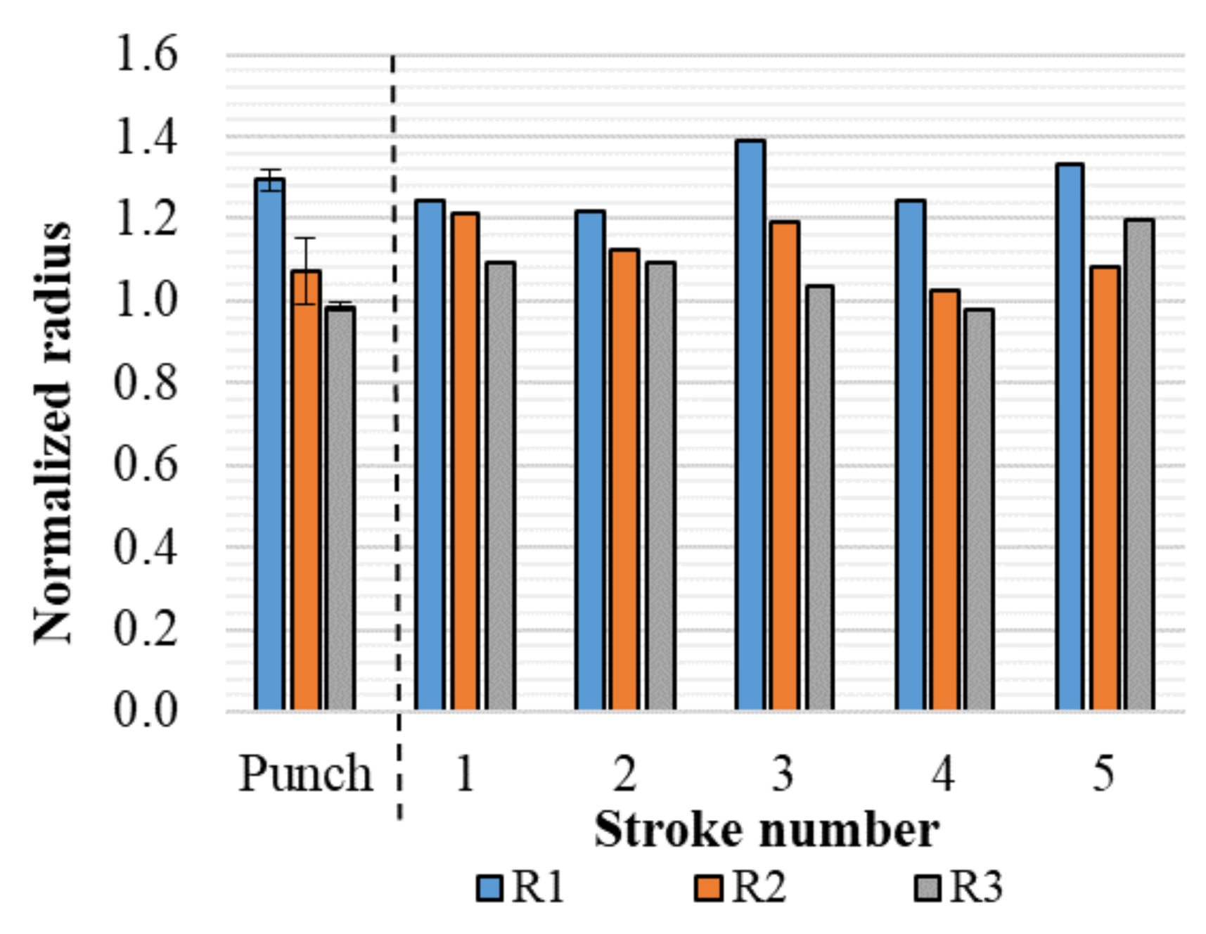
3.3. Bend Radius
4. Groove Pressing
5. Conclusions
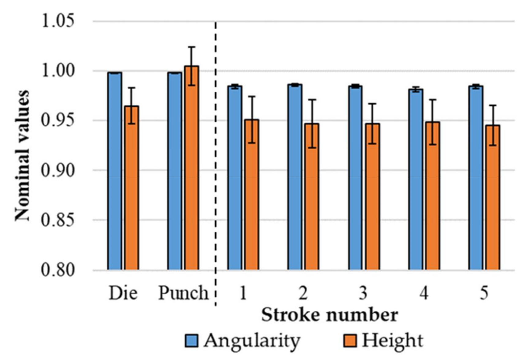
- Steady-state conditions were achieved in five strokes for the tool assembly with minimal wear detected in following strokes.
- The elastic deflection of the tools influence forming stroke and the final geometry after spring-back.
- The radius of the punch nose in V-bending should be considered relative to the shell-thickness used in printing the tools for optimal results.
- It is possible to form more complex shapes, which was here exemplified by groove pressing.
- Some compensation for spring-back will be possible due to low scatter in the final geometries.
Author Contributions
Funding
Conflicts of Interest
References
- Klimyuk, D.; Serezhkin, M.; Plokikh, A. Application of 3D printing in sheet metal forming. Mater. Today Proc. 2021, 38, 1579–1583. [Google Scholar] [CrossRef]
- Zelený, P.; Vána, T.; Stryal, J. Application of 3D printing for specific tools. Mater Sci Forum. 2016, 862, 316–323. [Google Scholar] [CrossRef]
- Zaragosa, V.G.; Strano, M.; Iorio, L.; Monno, M. Sheet metal bending with flexible tools. Proc. Manuf. 2019, 29, 232–239. [Google Scholar] [CrossRef]
- Durgun, I. Sheet metal forming using FDM rapid prototype tool. Rapid Prototyp. J. 2015, 21, 412–422. [Google Scholar] [CrossRef]
- Nakamura, N.; Mori, K.; Abe, F.; Abe, Y. Bending of sheet metals using plastic tools made with 3D printer. Proc. Manuf. 2018, 15, 737–742. [Google Scholar] [CrossRef]
- Schuh, G.; Bergweiler, G.; Bickendorf, P.; Fiedler, F.; Colag, C. Sheet metal forming using additively manufactured polymer tools. Proc. CIRP 2020, 93, 20–25. [Google Scholar] [CrossRef]
- Aksenov, L.B.; Kononov, I.Y. Thin sheet forming with 3D printed plastic tool. Solid State Phenom. 2020, 299, 705–710. [Google Scholar] [CrossRef]
- Dynamism, Ultimaker 2+. Available online: https://www.dynamism.com/ultimaker/ultimaker-2-plus.html (accessed on 29 April 2021).
- Kuznetsov, V.E.; Solonin, A.N.; Urzhumtsev, O.D.; Shilling, R.; Tavitov, A.G. Strength of PLA components fabricated with fused deposition technology unsing a desktop 3D printer as a function of geometrical parameters of the process. Polymers 2018, 10, 313. [Google Scholar] [CrossRef] [PubMed] [Green Version]
- Zhou, J.G.; Herscovici, D.; Chen, C.C. Parametric process optimization to improve the accuracy of rapid prototype stereolitography parts. Int. J. Mach. Tools Manuf. 2000, 40, 363–379. [Google Scholar] [CrossRef]
- Naik, D.L.; Kiran, R. On anisotropy, strain rate and size effects in vat photo polymerization based specimens. Additive Manuf. 2018, 23, 181–189. [Google Scholar] [CrossRef]
- Aslani, K.E.; Chaidas, D.; Kechagias, J.; Kyratsis, P.; Salonitis, K. Quality performance evaluation of thin walled PLA 3D Printed parts using the teguchi method and grey relational analysis. J. Manuf Mater. Process. 2020, 4, 47. [Google Scholar] [CrossRef]
- Aznarte, E.; Ayranci, C.; Qureshi, A.J. Digital light processing (DLP): Anisotropic tensile consideration. In Proceedings of the Solid Freeform Fabrication 2017: Proceedings of the 28th Annual International Solid Freeform Fabrication Symposium: An Additive Manufacturing Conference, Austin, TX, USA, 7–9 August 2017; pp. 413–425. [Google Scholar]


| Material | ρ (kg/m3) | E (GPa) | ν (-) |
|---|---|---|---|
| AL1050 | 2710 | 71 | 0.3 |
| Polylactic acid (PLA) | 1230 | 2 | 0.3 |
| Photopolymer | 1120 | 2.7 | 0.36 |
| Printing Technology | Exposure Time | Orientation | Layer Thickness | Shell Thickness | Infill Density | Post Processing |
|---|---|---|---|---|---|---|
| FFF | - | Vertical | 0.1 mm | 2.10 mm | 50% | - |
| VPAM | 3.5 s | Vertical | 0.1 mm | - | 100% | UV curing at 45 °C for 30 min |
| Stroke (#) | 0 | 3 | 5 | 10 | 30 |
|---|---|---|---|---|---|
| Punch |  | 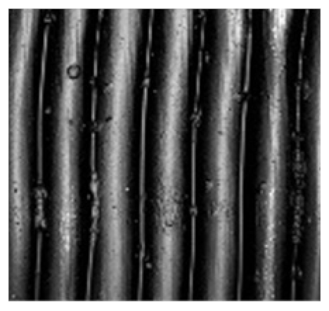 |  | 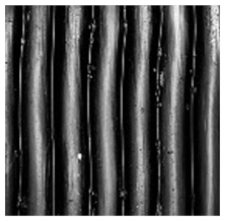 | 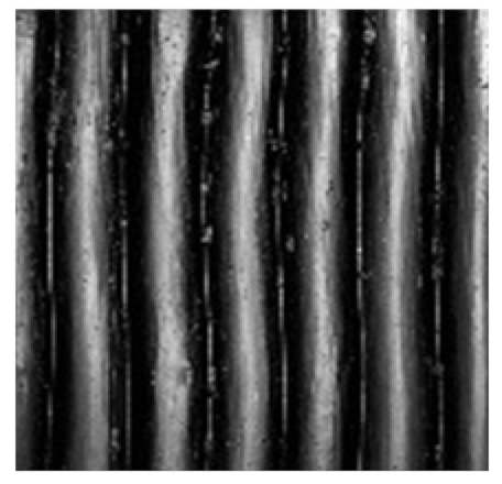 |
| Die | 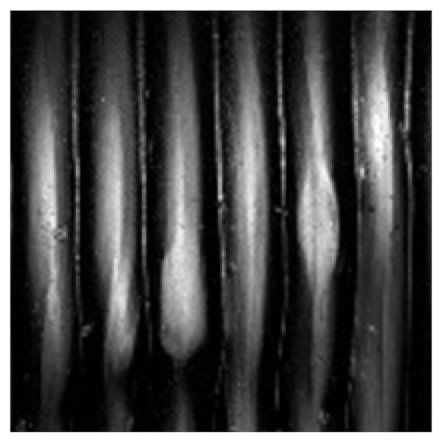 | 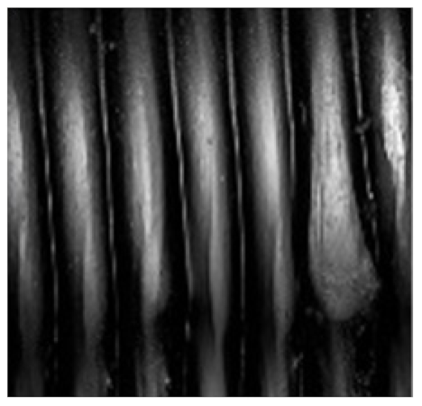 |  | 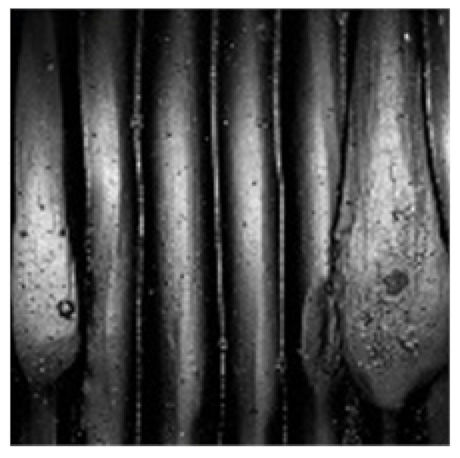 |  |
Publisher’s Note: MDPI stays neutral with regard to jurisdictional claims in published maps and institutional affiliations. |
© 2021 by the authors. Licensee MDPI, Basel, Switzerland. This article is an open access article distributed under the terms and conditions of the Creative Commons Attribution (CC BY) license (https://creativecommons.org/licenses/by/4.0/).
Share and Cite
Tondini, F.; Basso, A.; Arinbjarnar, U.; Nielsen, C.V. The Performance of 3D Printed Polymer Tools in Sheet Metal Forming. Metals 2021, 11, 1256. https://doi.org/10.3390/met11081256
Tondini F, Basso A, Arinbjarnar U, Nielsen CV. The Performance of 3D Printed Polymer Tools in Sheet Metal Forming. Metals. 2021; 11(8):1256. https://doi.org/10.3390/met11081256
Chicago/Turabian StyleTondini, Fabio, Alberto Basso, Ulfar Arinbjarnar, and Chris Valentin Nielsen. 2021. "The Performance of 3D Printed Polymer Tools in Sheet Metal Forming" Metals 11, no. 8: 1256. https://doi.org/10.3390/met11081256
APA StyleTondini, F., Basso, A., Arinbjarnar, U., & Nielsen, C. V. (2021). The Performance of 3D Printed Polymer Tools in Sheet Metal Forming. Metals, 11(8), 1256. https://doi.org/10.3390/met11081256