Article

Analysis of the Process Parameters, Post-Weld Heat Treatment and Peening Effects on Microstructure and Mechanical Performance of Ti–Al Dissimilar Laser Weldings

1
Innovation Engineering Department, University of Salento, Via per Arnesano s.n., 73100 Lecce, Italy
2
Politecnico di Bari, DMMM, Via Orabona, 4, 70125 Bari, Italy
*
Author to whom correspondence should be addressed.
Metals 2021, 11(8), 1257; https://doi.org/10.3390/met11081257
Submission received: 7 July 2021 / Revised: 30 July 2021 / Accepted: 2 August 2021 / Published: 9 August 2021
(This article belongs to the Special Issue Advances in Laser Materials Processing)

Abstract

:
Dissimilar Ti–Al laser weldings are very interesting due to their difficulties in being processed because of the different physical properties of the alloys and the crack formations during cooling and solidification. In this study, the effect of laser offset and defocusing on microstructure, geometry and mechanical properties response of 2 mm thick dissimilar AA6061/Ti-6Al-4V laser welds was analyzed. Moreover, in order to reduce residual stresses, the joints were both heat-treated and mechanically treated by ultrasonic peening. The welds microstructure was found to be martensitic in the Ti-6Al-4V fusion zone, columnar dendritic in the AA6061 fusion zone and partially martensitic in the Ti-6Al-4V heat-affected zone. Intermetallic compounds based on the Al–Ti system were detected at the AA6061/Ti-6Al-4V interface and in the aluminum fusion zone. Both negative defocusing and higher laser offset improved the tensile performance of the welds, mainly by reducing the amount of brittle intermetallic compounds. The stress relaxation heat treatment, leading to the aging of the martensite and the increasing of the size of the intermetallic compound, reduced the tensile strength and ductility of the joints. On the contrary, for dissimilar Al–Ti welds, mechanical treatment was effective in increasing joints ductility and, moreover, corrosion resistance.

1. Introduction

Titanium (Ti) and aluminum (Al) alloys are characterized by low density (equal to 4.43 g/cm3 for Ti and 2.80 g/cm3 for Al) and good mechanical properties (the average ultimate tensile strength is equal to 300 MPa for Al Alloys and 1205 MPa for Ti alloys) [1]. Al–Ti dissimilar welds are of significant interest in aeronautical and automotive applications, where weight reduction, combined with high mechanical strength and corrosion resistance, is required. Moreover, cost reduction can also be obtained by using Aluminum alloy coupled with Titanium [2]. For example, the passenger seat track after AIRBUS conceptual design was manufactured with Ti6Al4V crown and aluminum alloy web by laser beam welding [3]. The benefits and the recent trend of laser welding of Ti/Al alloys in the academic sector and industry were explored by Quazy et al. [4]. Recent trends also enclose dissimilar Al–Ti laser weldings based on high-strength aluminum–lithium alloys for aviation applications [5,6].
However, joining of Al/Ti alloys remains a difficult technological challenge because of the different physical properties and the formation of intermetallic phases (IMC) that lead to crack formation during cooling and solidification [4,7,8]. The successful joining of aluminum to titanium requires the reduction of the thickness of IMC layer at the interface as well as of the number of IMC particles dispersed on the aluminum fused zone (FZ). In fact, although intermetallic compounds based on Ti–Al system are attractive, being characterized by good strength at high temperature, the development of IMC leads to restrictions on the available deformation modes. So, the occurrence of those particles is associated with increased strength but reduced ductility and fracture toughness [5].
Both the convective mixing and diffusion phenomena that increases the occurrence of IMC can be limited by diffusion bonding [6] friction welding [7], laser welding [4] of these alloys. In laser welding, the mismatch in thermophysical properties of chosen dissimilar alloy can be adjusted by shifting the laser beam to one of the substrates. For example, according to [4], a shift of the laser beam to the aluminum side promoted the formation of a thin IMC layer and yielded a high tensile strength, whereas a shift to the titanium side promoted the formation of a thick TiAl3 phase that contained cracks and voids. On the contrary, according to [8], the thickness of IMC can be significantly reduced by shift the laser beam on Ti side.
In addition, defocusing the laser beam can modify the IMC thickness of the layer and IMC particles amount due to the change in the beam energy density and temperatures values [9]. The defocus distance is the position of the focal plane relative to the in focus beam plane. A negative defocusing distance occurs when the focal plane is placed under the “in focus” plane, whereas in positive defocusing, the focal plane is above it. The negative defocusing leads to a deeper melt pool due to its convergent nature, by comparing with in focus and positive defocusing. Particularly, when keeping constant laser power and scanning speed, the defocusing distance (positive and negative sense) can affect the microstructure and defects presence [9,10,11].
Post welding heat treatments (PWHT) are usually applied to the welds. The welds residual stresses may lead to brittle fracture and reduced fatigue life [9,10]. In addition, the increased dislocation density in fusion welds can reduce ductility of the joints [12]. As the PWHT temperature increases, residual stresses and dislocation density are reduced faster. In the case of dissimilar Al–Ti welds the different properties of the alloys, limit the feasibility of an effective stress relief heat treatment. For example, a significative control of the Ti-6Al-4V welds could require heat treatments at temperature higher than the liquidus temperature of Al Alloys [12]. Moreover, the highest temperature suitable must also avoid grain size and IMC coarsening resulting in decreasing of strength and ductility [13,14]. Many studies were devoted to defining the role of PWHT on microstructure and IMC growth for dissimilar welds. For example, for a laser welded AA5754/Ti-6Al-4 V joint, the microstructure of the IMC did not change after heat treatment at 350 °C for 336 h [13]. At 450 °C for 168 h, nucleation and growth of TiAl3 were observed with consequent decreasing of joint tensile strength [13]. In another study regarding forty-layered Ti–Al composites fabricated in a single-shot explosive welding process, the thickness of the TiAl3 layer was only 0.7 ± 0.1 μm after heat treatment at 500 °C for 100 h [15]. Solid-state diffusion between Ti and Al was investigated between 520–650 °C in multi-laminated Ti/Al [16]. The authors found that the thickness of the TiAl3 layer reached 10.50 ± 0.78 μm and 24.11 ± 5.85 μm after annealing at 520 °C-4 h and 650 °C-64 h [16].
As an alternative to the PWHT, mechanical treatments can be applied to reduce residual stress of welds. The ultrasonic peening treatment (UPT) aims to redistribute residual stresses by eliminating tensile stresses and introducing compressive stresses [17,18]. The principle is the same as hammer peening [19,20] and consists of subjecting the material surface to a plastic compression deformation through a hammer gun that vibrates. In the case of UPT, the hammer gun vibrates at high frequency due to a piezoelectric actuator [17,18]. It has been shown [21] that UPT induces a nanocrystalline surface layers with increased microhardness. The nanocrystalline surface layer also enhanced the corrosion resistance of the Zr-2.5%Nb alloy in saline solution [21]. Moreover, this technique allows micro-cracks and pores closure [18] that are well-known to improve the fatigue strength. The efficiency of the UPT treatment obviously depend on the geometry of the impactor, on the percussion intensity and on the duration of the treatment. These parameters need to be accurately regulated to avoid that the treatment is too mild and thus ineffective, but at the same time not too much severe, to not irremediably damage the material [22]. Most papers study the effects of UPT on fatigue behaviors showing that under correct conditions UPT produces high improvement in fatigue life [23,24,25] or wear and corrosion resistance [21,22]. However, few investigations aimed to evaluate the effects of UPT on tensile properties of laser welded dissimilar joints.
In this paper, Al-Mg -Si alloy was laser welded to Ti-6Al-4V alloy. The effect of both focused and negative defocused beam coupled with two different laser offset values on fusion zone size, heat-affected zone size, intermetallic compounds occurrence and amount, hardness and tensile performance were investigated. Moreover, the occurrence and distribution along the thickness of the intermetallic particles has also been characterized. Stress relaxation heat treatment effects at 530 °C for 2 h followed by air cooling on the joints mechanical properties has been analyzed in term of hardness measurements and tensile test. The stress relaxation heat treatment effects were compared with those induced by the mechanical treatment of the joints. Potentiodynamic polarization test in NaCl solution was used to study the corrosion resistance both of aluminum alloy and welds before and after mechanical treatment. The novelty of this study is that it provides a hitherto unexplored chance to overpass the main limit of the dissimilar joints that is the low ductility by the mean of a mechanical treatment.

2. Materials and Experimental Methods

The chemical compositions of as-received Al and Ti alloys are shown in Table 1 and Table 2. Butt joints Al-Mg-Si/Ti-6Al-4V were processed on 2 mm plates. The laser beam was focused on the Titanium side (Figure 1), respectively, 0.1 mm and 0.3 mm away from the aluminum edge, which is the laser offset. For each fixed laser offset, two different laser beam focus positions were used as in the schemes of Figure 1: in focus beam named T as Top (focus at the top of the thickness joint) and negative laser defocusing (−2 mm) named B as Bottom (defocused beam at the bottom of the thickness joint), respectively.
In Figure 1, the macrostructure of the welds cross section is also shown. So, four samples were processed. The welding speed was 2500 mm/min and the laser power 1500 W. An Ytterbium Fiber Laser System (IPG YLS-4000), with a maximum output power equal to 4 kW was used for the welding. The laser beam was delivered with a diameter equal 200 μm and has a beam parameter product (BPP) equal to 6.3 mm/rad. The laser beam has a wavelength of 1070.6 nm. Argon and helium were employed as shielding gas with volumetric flow rate equal to 10 L/min. Particularly, since helium has a specific weight less than atmospheric air, it was employed for the bottom surface, while the heavier Argon was used on top surface.
The welds were cut perpendicular to the welding direction to characterize the transverse section. They were analyzed by optical microscopy (OM; Nikon Epipkot 200) and scanning electron microscopy (SEM; Zeiss EVO 40) equipped with energy dispersive spectrometer (EDS Bruker). The cross sections of the samples were prepared using the standard metallographic grinding and polishing techniques and attached using Keller reagent (95 mL H2O, 2.5 mL HNO3, 1.5 mL HCl, HF 1 mL). The grain structure was revealed by electro-polishing (20% perchloric acid and 80% ethanol at 0 °C, electro-polishing parameters: 15 V and 60 s), anodic oxidation (Barker etching, anodizing parameters: 20 V and 80 s) and subsequent investigation under polarized light in OM. The area size of FZ, HAZ and intermetallic layer were evaluated using NIS-Element software for imaging analysis. In addition, the width of FZ at different position along the thickness of the joints were evaluated using NIS-Elements. NIS Element is a NIKON software supplied with Epiphot 200 OM. The software is tailored to facilitate image capture, object measurement and counting. The role of the energy density on hardness evolution was investigated by Vickers indentation in the cross section of the joints along a line perpendicular to joint interface. For Vickers microhardness profiles, a Vickers Affri Wiky 200JS2 microhardness tester was used, with load 0.3 kg and time of indentation 15 s (0.3/15 s). The distance between indentations was equal to 300 µm. For the joints T and B, the hardness measurements were done 200 and 1800 µm from upper surface. All the welded joints were subjected to tensile tests. Rectangular samples (length: 20 mm; width: 5 mm; thickness: 2 mm), with sample length perpendicular to the weld line, were cut for tensile test. Tensile tests were carried out on a servo-hydraulic testing machine having MTS810 having a load capacity of 100 kN. The samples were tested using strain rate equal to 0.2 mm/min. The joints 3T and 3B, characterized by having best mechanical performances, were further treated by stress relief heat treatment (SRHT) at 530 °C-2 h to relax welding thermal stress. After that, joints 3B and 3T were characterized in terms of hardness at a half of thickness and tensile tests. On the welded joints 3T and 3B, UPT was applied only on the Aluminum longitudinal surfaces for 1 min/side by an Ultrasonic Peening Sintes UP 600. The diameter of the peening needle was 3 mm and the vibration frequency was 20 kHz. The treated zone (about 6 mm from the Al/Ti interface) included both Al FZ, HAZ and BM.
Electrochemical measurements were performed with an AMEL 5000 potentiostat/galvanostat in an aqueous 3.5% NaCl solution. All experiments were conducted in naturally aerated, near neutral solutions at ambient temperature. A conventional three-electrode cell was employed, with a platinized titanium expanded mesh counter electrode, a Ag/AgCl reference electrode and a specimen of AA6061 aluminum alloy, before and after UTP, as a working electrode. All the potentials were referred to Ag/AgCl. The samples were insulated using teflon to mask their cut edges and back sides, in order to leave only a surface area of 0.5 cm2 exposed to the electrolyte. The steady state potential was determined after 60 min of immersion in the solution at open circuit potential (OCP). Following the determination of the steady state OCP, potentiodynamic polarisation measurements were performed from −0.15 V vs. OCP to +1.5 V vs. Ag/AgCl at a scan rate of 1 mV s−1. Each corrosion test was repeated on two samples.

3. Results and Discussion

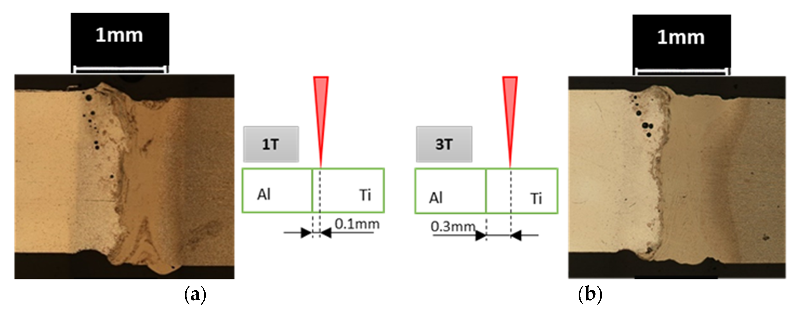
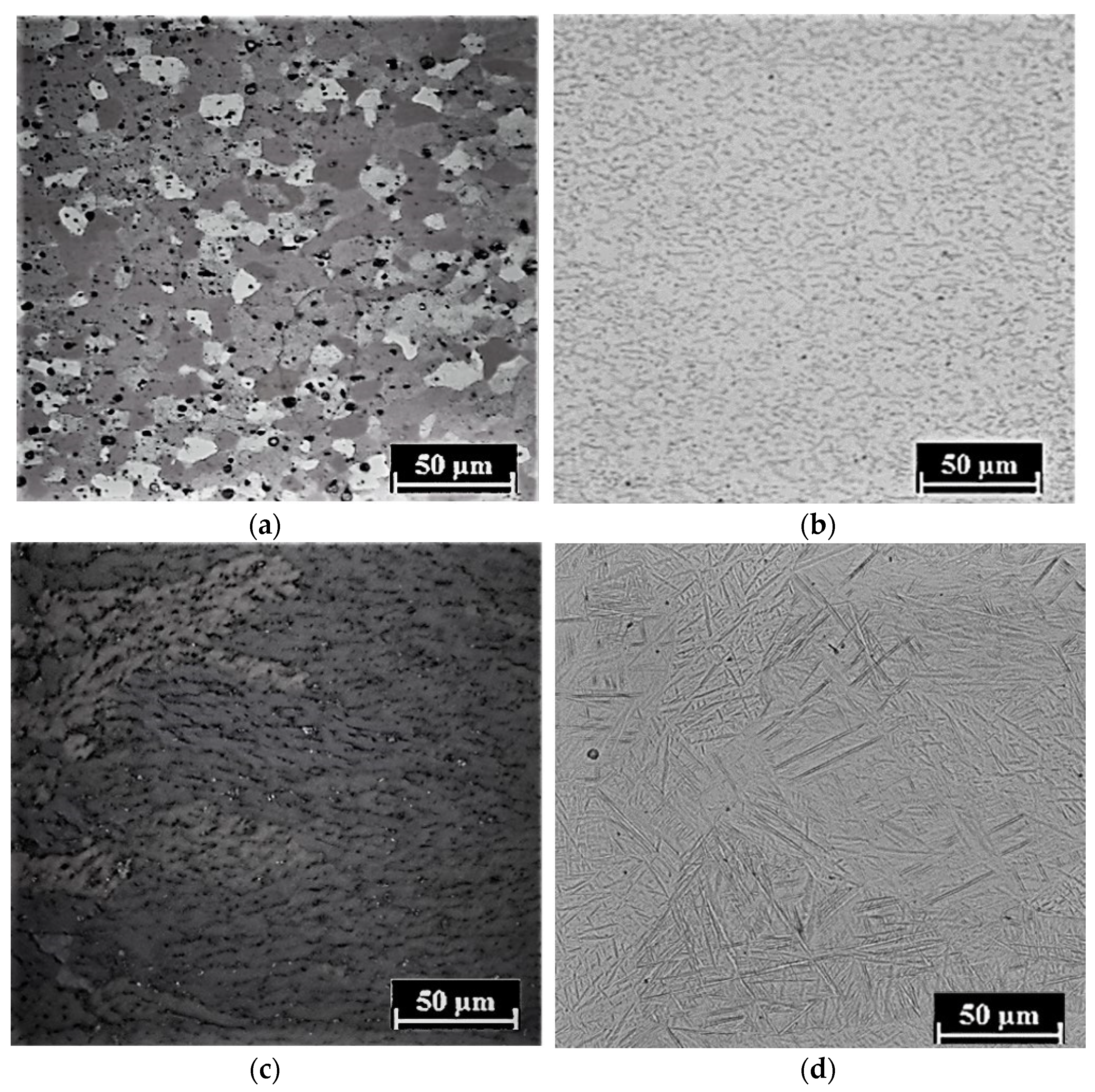
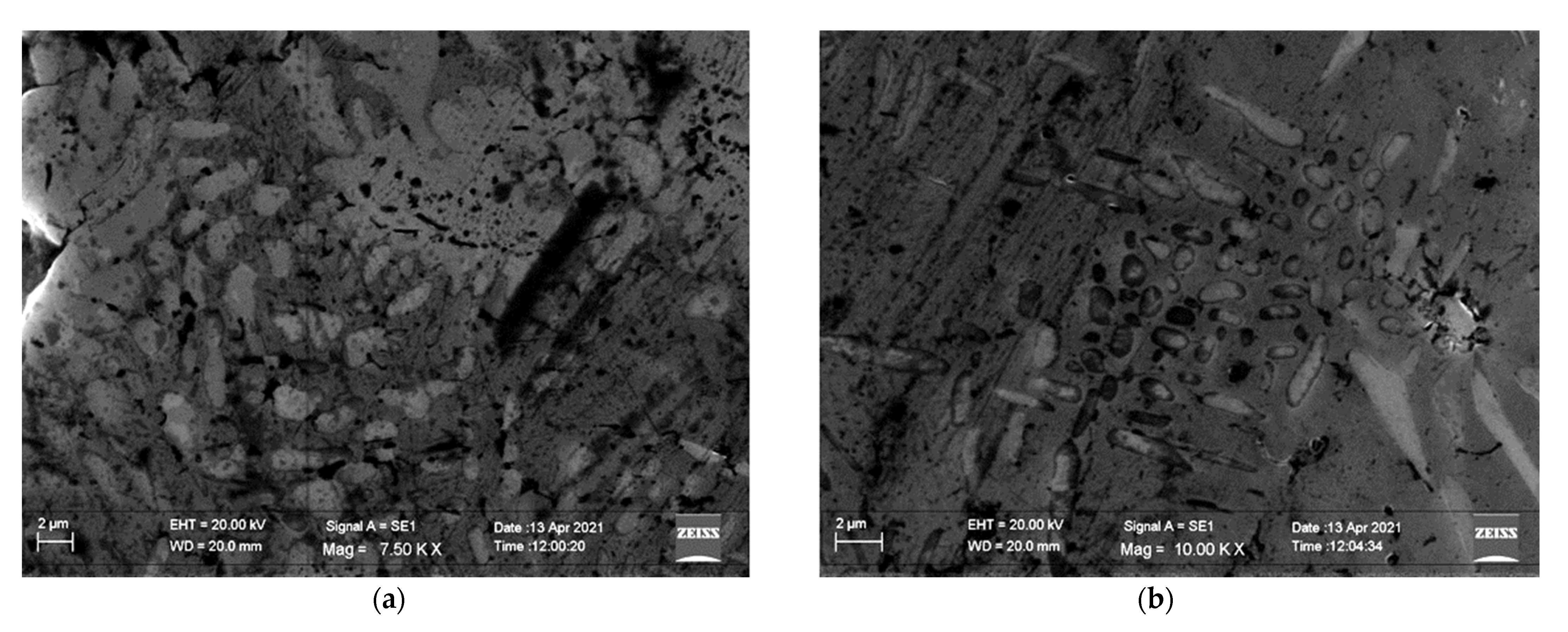
3.1. Analysis of Welds Macrostructure and Microstructure

The macrostructure of the joints is shown in Figure 1 together with the scheme of the processing. The chemical etchant clearly reveals the different zones of the joints consisting of unaffected base material (BM), FZ and HAZ. In addition, highlighting the intermetallic layer (IMCL) at the interface. Some small round pores can be observed in the FZ, above all on the Al side.
The BM AA6061, supplied in the annealed condition, is a precipitation-hardenable aluminum alloy, containing magnesium and silicon as its major alloying elements. Figure 2a highlights the annealed grains of the alloy. The Vickers micro-hardness (HV0.3/15) is 52.5 ± 1.15. The Titanium base material is supplied in mill annealed condition and the microstructure is characterized BCC (body-centered cubic) beta phase (darker zone in Figure 2b) that outlines the HCP (hexagonal closest packed) alfa phase (lighter in Figure 2b). The Vickers micro-hardness (HV0.3/15) of the alloy is equal to 290.3 ± 10.2.
All the joints exhibit an aluminum fusion zone with columnar grains that grow from the HAZ/FZ interface towards the Ti side (Figure 2c). The growth of columnar grains, promoted by steep heat gradient, occurred in the opposite direction of the heat flow (perpendicular to the FZ/HAZ interface). In the HAZ of the aluminum alloy, coarsening or dissolution of soluble Mg2Si particles, developed due to annealing of BM, can happens [25,26,27,28,29,30,31]. The particles dissolution is more significant as the distance from fused zone is reduced since, being closer to the fusion zone, the HAZ thermal cycle is characterized by higher peak temperature [9,10]. Figure 3a shows the evolution of the 3B joint Al side microstructure in the different zones (FZ, HAZ) with respect to the BM.
In the titanium side, FZ, the microstructure is martensitic (α′), as shown in Figure 2d [5,27,30]. In fact, as reported in the literature [5,8,9,10,13,31], the microstructure of the laser fusion zone of Ti-6Al-4V alloy is due to the complete evolution of the beta phase microstructure to martensitic one due to the high cooling rate. The HAZ is a mixture of martensitic and primary α grain [5,8,13,31]. In the HAZ, during the welding heat thermal cycle, an increase of β phase occurs upon heating but, due to the lower peak of temperature, this transformation is never complete and some alpha phases remain unchanged, while the transformed beta grains develop the martensitic microstructure upon cooling. Figure 3a shows the evolution of the Ti side microstructure in the 3B joint in the different zones (FZ, HAZ) with respect to the BM.

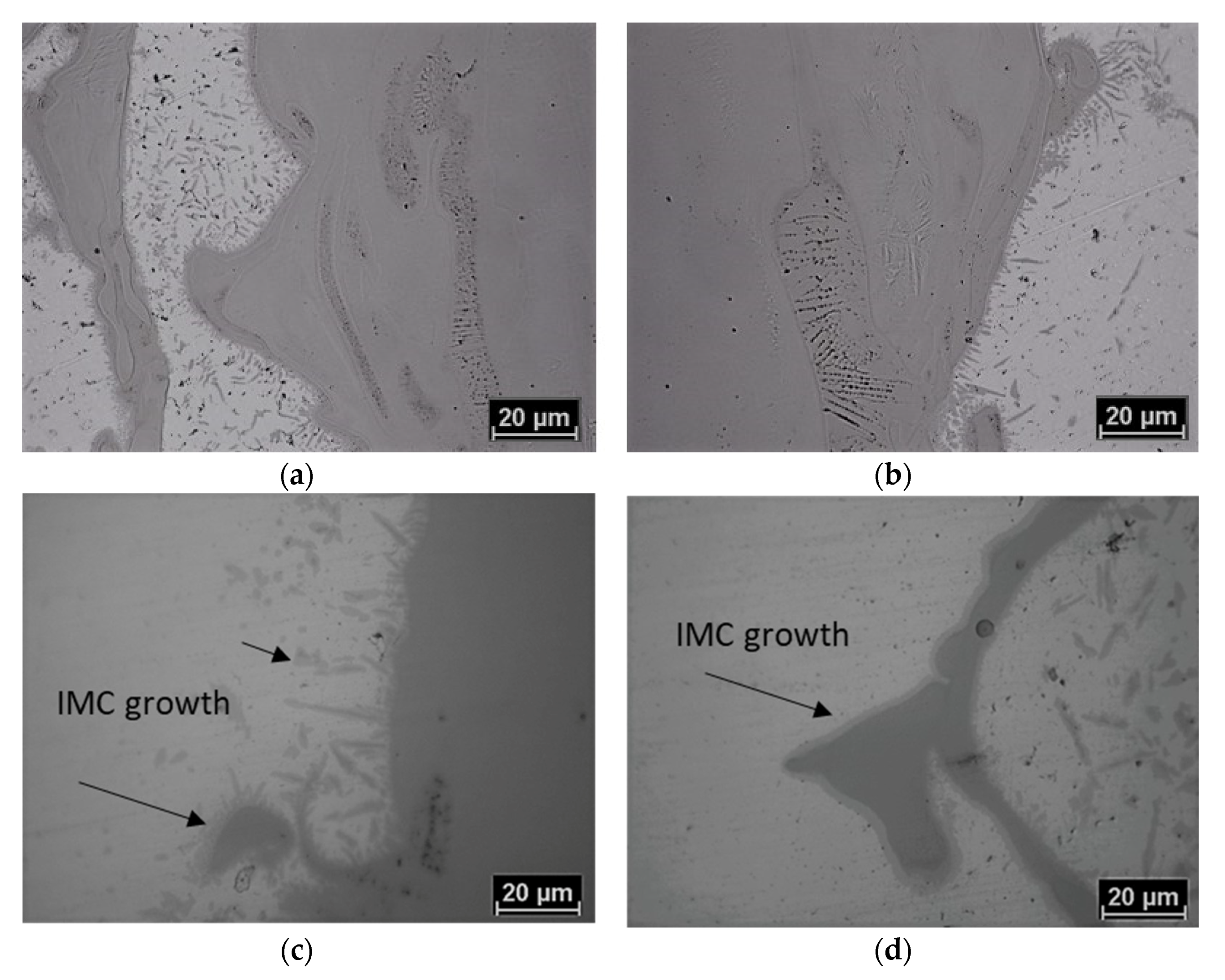
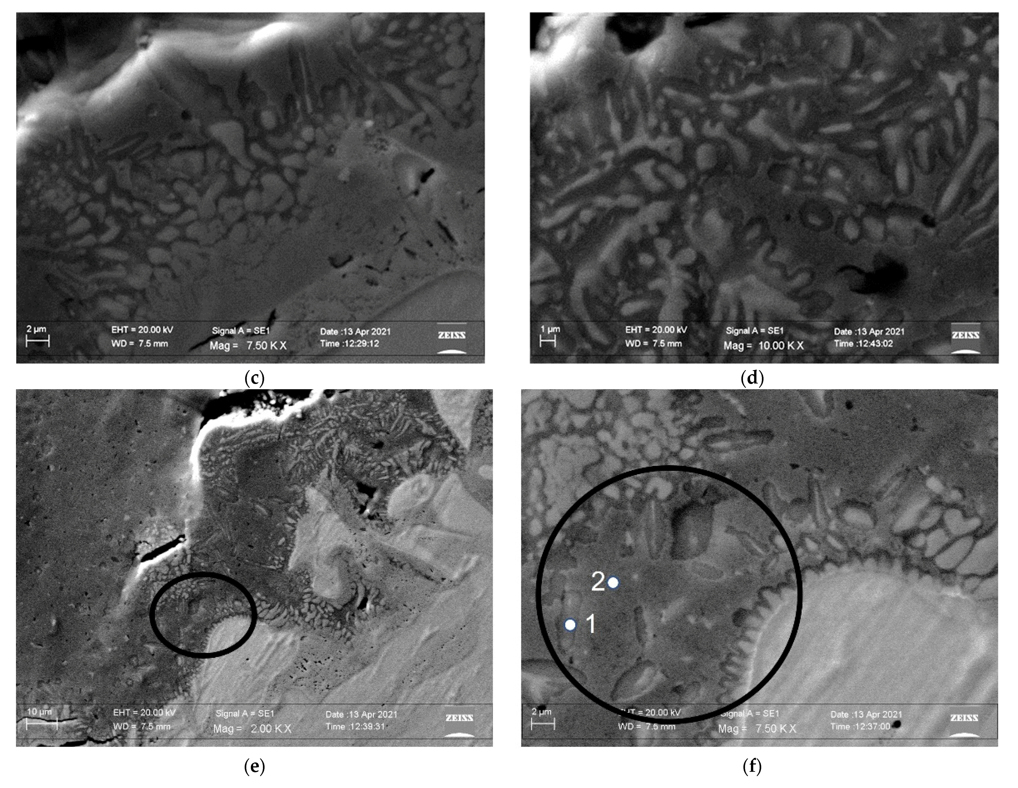
3.2. Intermetallic Layer and Geometry of Welds Fusion Zones

The IMCL generated during welding at the Al/Ti fused zone interface is due to the melting and mixing of the different alloys. The shape of the intermetallic layer change with process parameters. At fixed defocusing, the interlayer was more curved when the offset was small (Figure 1). At fixed offset, the shape of IMCL become flatter with decreasing defocusing (Figure 1). In fact, both in focus beam and low laser offset promote higher temperature close to the interface favoring convective mixing of the melted alloys, as well as atomic diffusion [8,13]. Consequently, the thickness of the interlayer was also lower with negative defocusing (samples B exhibit lower size of IMCL with respect to the samples T in Figure 4) and increased laser offset (samples 3 exhibit lower size of IMCL with respect to the samples 1 in Figure 4).
For the same previously discussed role of energy density on the mixing of two alloys, acicular IMC particles could nucleate and grow mainly in the welds processed with focused beam (Figure 5a,b) thanks to the augmented titanium atoms concentration next to the interlayer (Figure 5).
The microstructure of the FZ and HAZ of all the joints does not change with process parameters. Nevertheless, the size and geometry of the different zones exhibit some differences, as shown in Figure 6 and Figure 7. Regarding the FZ and HAZ sizes, the joints 1T and 1B are characterized by a lower FZ and HAZ with respect to the joints 3T and 3B (Figure 6a). Moreover, for the Ti side of joints 1T and 1B, those sizes slightly decreased with defocusing. In the joints 3T and 3B, due to the higher distance of laser beam from the Al alloy, the heat input is better confined in the Ti side. The lower heat conductivity of this alloy [5,9,10,27,29] leads to higher time in temperature and promotes higher size for the FZ and HAZ (Figure 6b). This effect is strengthened by the lowering of energy density with negative defocusing, as better shown below in Figure 7, that leads to lower temperature gradient [9,10].
For the joints 1T and 1B, the heat input better involves the aluminum side, which easily conducts away the heat due to its higher heat conductivity [5,9,10,27,29]. Therefore, the size of the FZ are reduced with respect to the joints 3T and 3B (Figure 6). The high thermal conductivity of aluminum alloy also compensates the effect of the negative defocusing, so the Al side fused zones do not change significantly with defocusing, while Ti FZ and HAZ are decreased.
The geometry of the joints FZ at different process parameters was evaluated by measuring the width of FZ along the joints thickness. Three measurements were made for each welds, respectively, at 200 µm, 1000 µm and 1800 µm from the top surface, as shown in Figure 7. The defocused beam strengthens the effect of Ti and Al heat conductivities on the size of FZ; therefore, the size of joint 3B along the thickness is always higher than the size of 3T joint (Figure 7b), while the opposite happens for joints 1T and 1B (Figure 7a).
For the joints processed with the laser offset equal to 0.3 mm, the highest difference in size with defocusing width was found to be 200 µm from the top (in the Ti side, it was equal to 700 micron for 3T vs. 960 micron for 3B). Even for the Al side, the highest increasing of width is registered at 200 µm from the top surface, but the width of Al FZ is more uniform along the joint thickness.
To summarize the results in Figure 6 and Figure 7, the FZ size is decreased (or increased) with decreasing (or increasing) laser offset. The negative defocusing strengthens the effect of laser offset by increasing (decreasing) the size of FZ at the high (low) laser offset. Therefore, the highest sizes of FZ and HAZ were observed for the 3B joint (Figure 6 and Figure 7). The most significant change in the geometry of the FZ size was observed for the Ti side of joint 3, where the width of FZ decreases moving from the top toward the bottom of the joints. The opposite happens for 1T/1B joints, but less significantly.

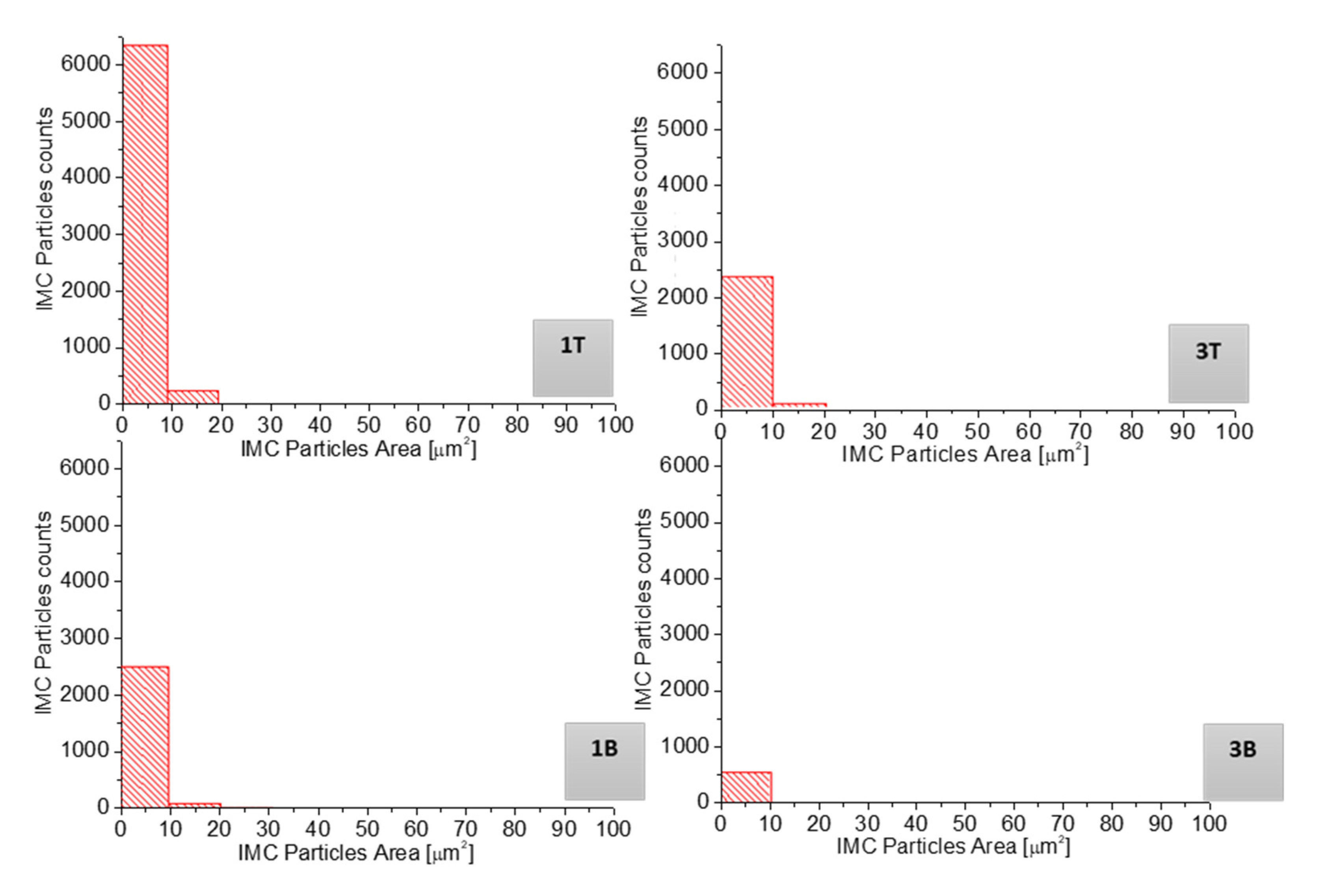
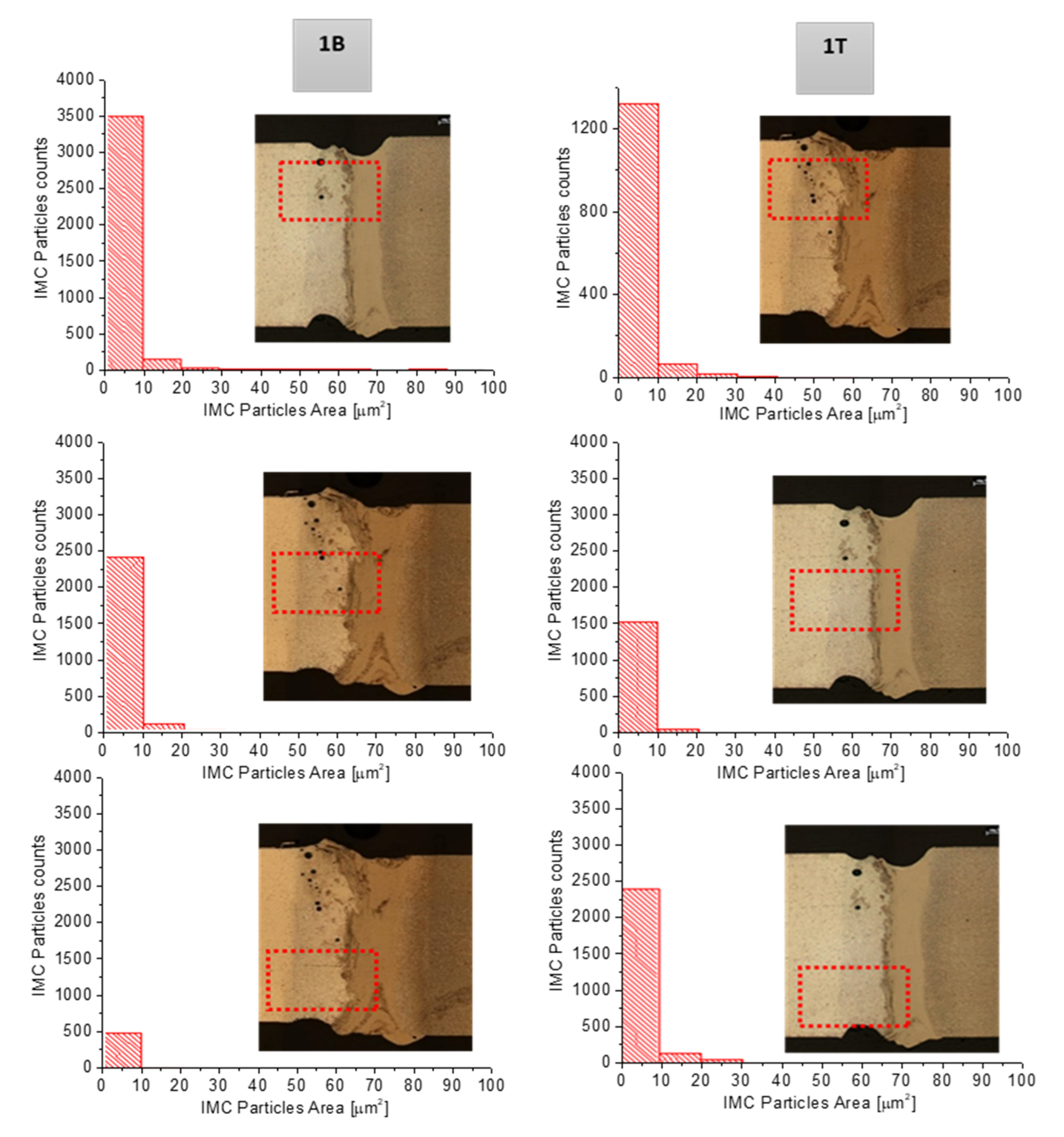
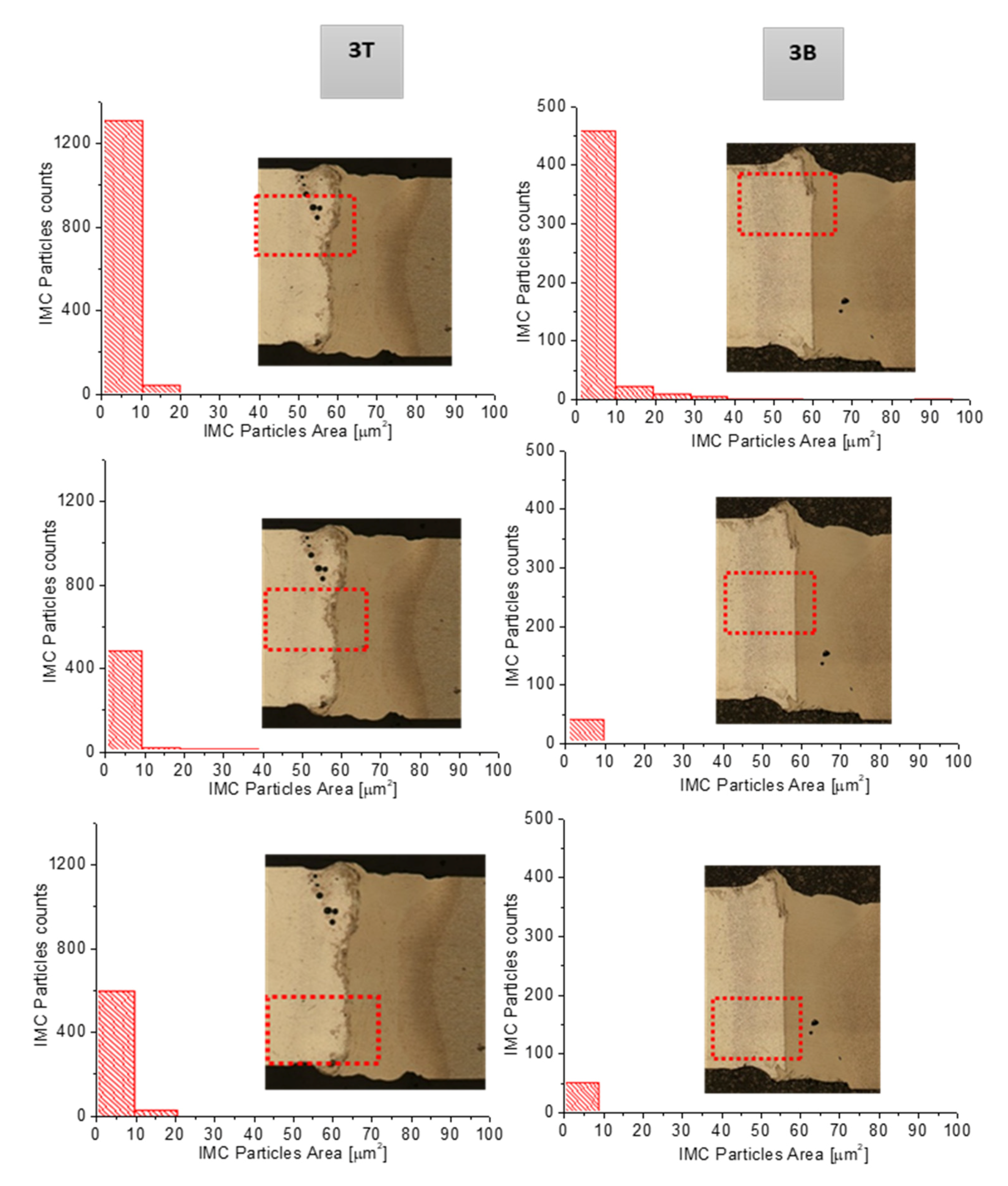
3.3. Intermetallic Particles: Count and Distribution

The effect of the process parameter on the occurrence and distribution of intermetallic particles in aluminum matrix was also investigated. The number and the size of particles at the Al–Ti interface was evaluated and showed as number of particles for classes of area (Figure 8). For all the welds, the highest number of particles had an area of lower than or equal to 10 µm. The number of particles is reduced by defocusing and, at fixed defocusing, it increases for the welds processed with laser offset equal to 0.1 mm, confirming the role of the peak temperature on the amount of IMC particles. Moreover, it is interesting to note that the number of particles decreases by 64%, comparing the 1T to the 3T joint (as well as from 1T to 1B) and decreases by 78% from the 1B to 3B joint (as well as from 3T to 3B). Therefore, the shift of 0.2 mm in the laser offset position leads to the same effect of a 2 mm shift in defocus distance.
A more detailed analysis on IMC particles distribution was developed, considering the number and distribution of the IMC particles along the thickness. The FZ of the Al side was divided in three rectangular window 1000 × 600 µm. The middle window was centered at a half of the thickness in the aluminum FZ. The other two windows are, respectively, on the top side (top window) and the bottom side (bottom window) of the central window, as in the schemes of Figure 9 and Figure 10. Inside each window, the number and size of the particles were counted. The analysis of the results shows that the amount of particles was always highest at the top of all the joints, even if, as showed previously, the maximum number decreases with negative defocusing and increased laser offset. The negative defocusing lead to energy loss and so lower average temperature at the interface; the same occurs when increasing the laser offset. In the T samples, the highest number of particles at the top of the joints is justified by the highest energy density and temperature, which favors a better mixing of the two alloys. For the negative defocusing, the increasing number of IMC particles at the top of the joints could be due to the divergent beam at the top, which imposes a longer time for cooling, favoring atomic diffusion [9,10,29].
The role of the energy density on hardness evolution was investigated by Vickers indentation (0.3/15 s) in the cross section of the joints along a line perpendicular to joint interface. For joints T and B, the hardness measurements were conducted, respectively, at 200 and 1800 µm away from the upper surface (Figure 11). These distances were chosen to investigate the role of energy density in the focus point (joints T) or defocused positions (joints B). By processing the welds using negative defocusing, the hardness values close to the AA6061/Ti interface were reduced. The beam defocusing reduces the hardness imposing lower cooling rate due to lower energy density and the consequent microstructure coarsening. Moreover, in 3T and 3B welds, the hardness values were closer to each other for the two different focus conditions (Figure 11b) in both the Al and Ti sides of the welds.
The effect of the defocused beam on the hardness values is mitigated as laser offset increases, probably due to the prominence of the Ti heat conductivity effect on the cooling rate. With increasing laser offset, Ti heat conductivity dominates the cooling rate and the microstructure evolution and, therefore, the gap in hardness due to beam defocusing is less significant with respect to the joints processed with laser offset equal to 0.1 mm.

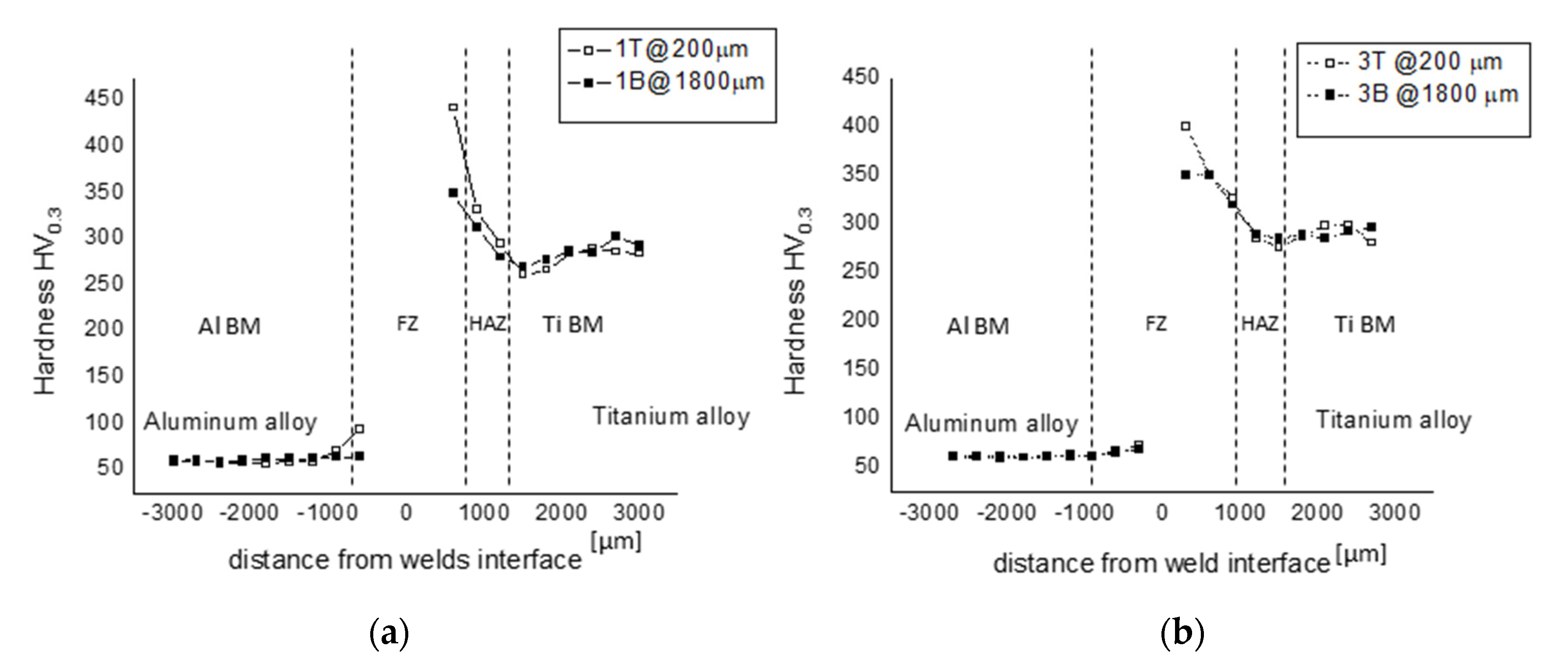
3.4. Mechanical Properties: Microhardness and Tensile Test of the as Welded Samples

Table 3 shows the average results after performing the tensile test on two specimens of each type. 3B and 3T welds exhibited the best tensile performances. As shown by the previous analysis, this behavior can be justified by the lowest thickness of IMCL, the lowest number of IMC particles and the lowest gap of hardness values at the interface (Figure 4, Figure 8 and Figure 11). Table 3 highlights the main limit of the joints that is the low value of ductility. Ductility values depend on microstructure [9,10] and intermetallic compounds developed in dissimilar Al–Ti welds that are very brittle [5,27,29,30], but also affected by residual stresses. Residual stresses are significant in the high energy density process (such as laser or electron beam welding) due to the severe temperature gradients and the high heating/cooling rate [9,10]. Residual stress leads to brittle fracture and reduced fatigue life and can be reduced both by heat treatments [9,10,12,13,14,15,16] and mechanical treatment [17,18,19,20,21,22,23,24,25].

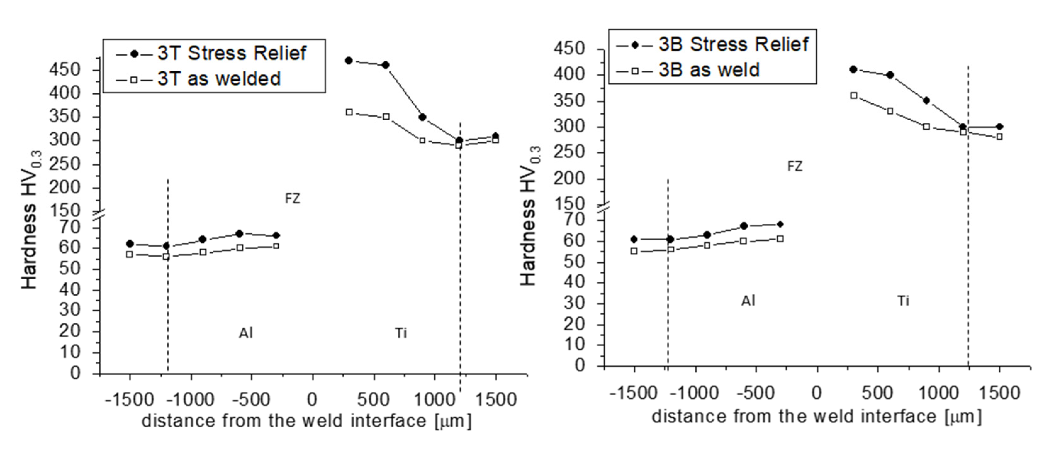
3.5. Microstructural Evolution and Mechanical Properties due to SRHT

For the analyzed joints, a feasible PWHT should reduce the residual stress without hardening the Ti side or softening the Al side in order to not further limit the ductility and toughness of the welds. A significative control of the Ti side microstructure requires heat treatments at temperatures higher than the Beta Transus Temperature of Ti-6al-4V (900 °C). Those values of temperature should lead to a completely BCC beta microstructure that allows one to obtain the appropriate microstructure and hardness values upon cooling. Such a temperature is higher than the melting point of AA6061 Al Alloy [27,28,30]. Moreover, the highest heat treatment temperature and holding time suitable for Al alloy must also avoid grain size coarsening. Therefore, the different properties of the alloys limit the effectiveness of the stress relief heat treatment. Considering that the liquidus T of the AA6061 alloy is equal to 582 °C [32], the temperature of the SRHT was chosen to be 530 °C and the holding time equal to 2 h, followed by air cooling. The treatment was applied to joint 3, characterized by the best mechanical performance (both strength and ductility). Hardness measurements were conducted on the cross sections of the heat-treated joints, at a half of thickness. The results indicate that the HAZ and FZ of Ti6Al4V harden significantly after SRHT, while in the AA6061 side, the increasing of hardness is not significant (five point more or less). In the Ti side, the highest increases of hardness, obtained close to the weld interface, were equal to 60 HV in 3B joint and 110 HV in 3T Joint (Figure 12).
The increase in the hardness of the Ti side is due to the aging of the martensite, which leads to the precipitation of hardening α + β particles [5,27,30,33]. In addition, some amount of the retained β phase could possibly exist in the FZ and HAZ welds due to rapid cooling. In this case, the effect of the heat treatment should lead to the microprecipitation of the α-phase platelet, it being the α phase most stable at low temperature. Therefore, from the transformation of the retained β, a further hardening effect is obtained, with the β-phase being comparatively soft and ductile relative to the α phase [5,27,30,33].
Moreover, it was also observed that the IMC thickness changes with the SRHT and both IMCL and particles in the Al matrix close to the interface grow up upon the SRHT. The average growth of IMCL was equal to 2.60 ± 0.6 μm and 1.30 ± 0.3 μm, respectively, for the 3T and 3B joints. The growth was evaluated along the thickness and it is also easily observable due to its lighter color in the optical micrographs, as shown in Figure 13. SEM micrographs at high magnification (Figure 14) allow one to better observe the growth of the IMC particles due to SRHT. In the SEM micrographs, the new compounds appear darker. According to the EDS analysis on the new nucleated particles (particle 1 in Figure 14f, Table 4) and the previous study of P. Leo et al. [13], the composition of the new nucleated and grown compounds is Al3Ti, being a thermodynamically favored compound at the highest percentage of aluminum [5,13,27,29].
Due to the microstructure evolution induced by SRHT, both the ductility and strength of the welds were reduced, as shown in Figure 15.
It is noteworthy that a previous study [33] showed that aging heat treatments of Al alloy in dissimilar Al–Ti welds could increase the tensile strength, but only with a strongly reduction of the ductility. In that work, the aging treatment at 180 °C required, as a first step, a solution treatment at a temperature higher than 500 °C. The low temperature heat treatment increased the strength of the Al side by the precipitation of a small and uniformed dispersion needle shaped Mg5Si6 particles named β″ [14,27,29,32], but the strong decrease in weld ductility could be mainly due to the first high temperature step. That first step is responsible for the increases in IMCL thickness/IMC particle size (Figure 13 and Figure 14) and for the strong increase in the hardness of the Ti side, as shown in Figure 12; as a consequence, the gap in the mechanical property at the weld interfaces results increased leading to reduced both fracture strength and ductility [33].
The main difficultly in providing good service performance of the dissimilar welds involves the low toughness and ductility. Therefore, the PWHT of the Al–Ti welds at temperatures higher than 500 °C is not the correct way to adjust tensile properties. Therefore, a possible application of UTP treatments is proposed in this study.

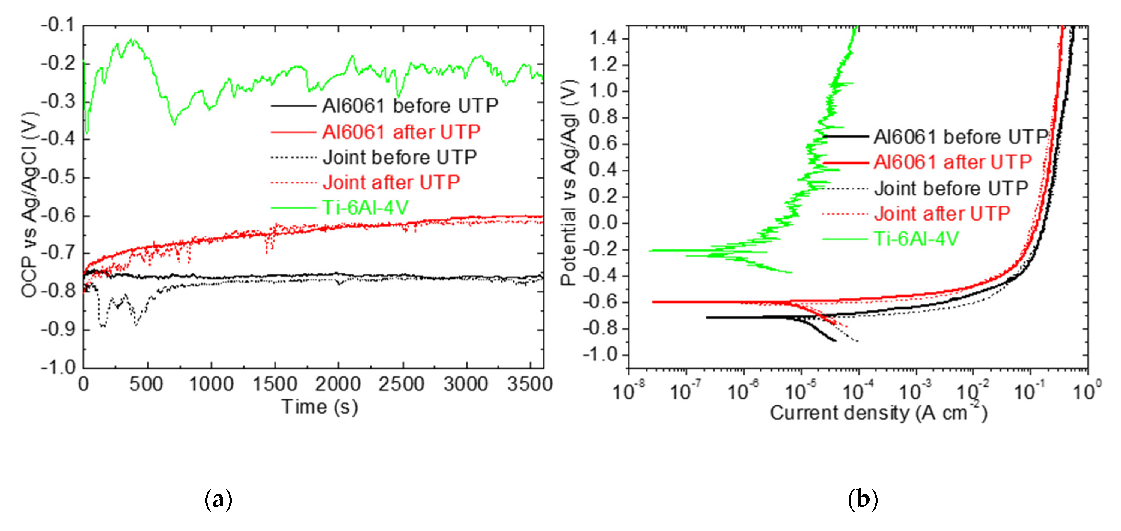
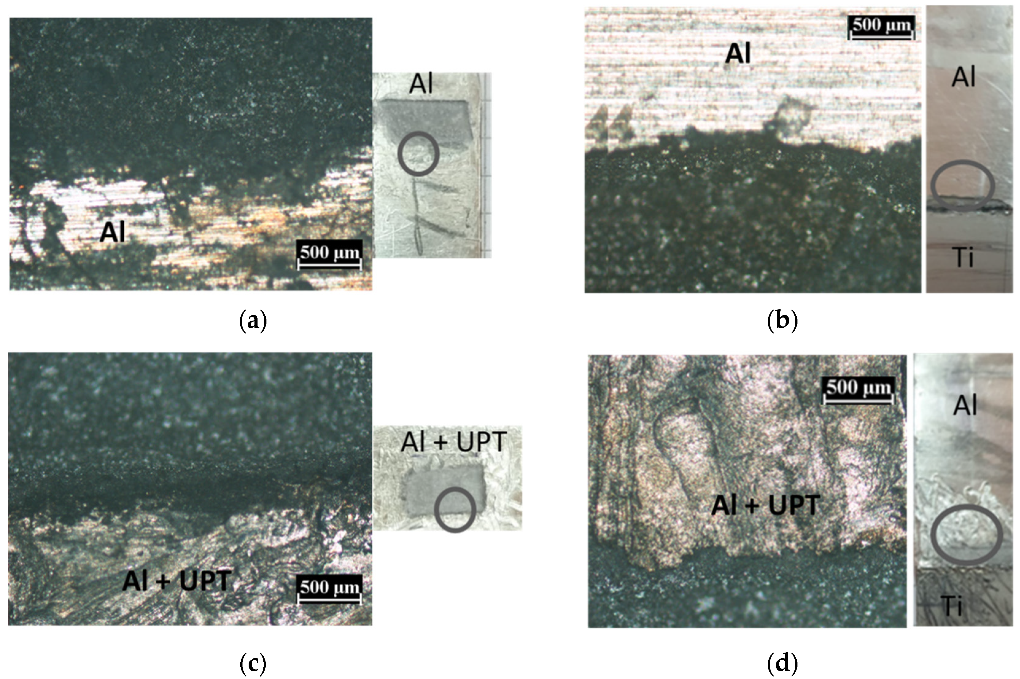
3.6. Role of UPT on Tensile Properties and Corrosion Resistance

The tensile curve of the 3B and 3T joints after UPT (Figure 15) are characterized by higher elastic modulus with respect the as welded ones. These results could be due to the reduction of porosity induced by UPT, as shown by Chawla et al. [34] and also verified by Tian et al. [18] for a AA6061 Al Alloy. The increases in fracture strain observed after UPT could be justified by the reduction of porosity together with the reduced strain hardening of the UPT samples (compare the tensile curves in Figure 15) [18,34]. In fact, even if the ultimate tensile strength of UPT is treated and welded samples do not differ significantly, the work hardening behavior is different (before and after UPT) because it is affected by the presence and the amount of residual stress [34,35]. To describe the mechanical behavior of the joints after UPT, residual stress analysis and work hardening characterization should be developed. As shown by Zhoua et al. [36], the reconstruction of the residual stress field associated with the work hardening is of great importance for an accurate assessment of the mechanical performances. Therefore, further detailed studies are necessary to define the relationship between mechanical properties and UPT treatment for Al/Ti dissimilar joints and possibly introduce further improvements. The data presented in this study are only intended to provide a hitherto unexplored chance to overpass the main limit of the dissimilar joints that is the low ductility.
In all the tensile samples, fracture cracks initiate in the Al FZ, at the interface with IMCL or IMC particles, and propagate mainly along the IMCL, as shown in Figure 15c–e by the micrographs of the tensile fracture cross sections of the 3B sample in a welded state, after UPT and after SRHT.
Figure 16a shows the variation of the OCP aluminum alloy before and after UPT, joint before and after UPT and Ti-6Al-4V specimens, in the near-neutral aqueous 3.5% NaCl solution, monitored for 60 min. As expected, the OCP value for the investigated AA6061 alloy is about −0.75 V vs. Ag/AgCl [37]. It is also evident that the OCP value of the treated sample becomes less negative during immersion until reaching a constant potential, probably due to the coarsening of the oxide film. A clear difference can be observed in the behavior of the two samples with an ennobling of the material obtained after the treatment. The significantly higher OCP values of titanium indicate its more noble behavior. The OCP values of the untreated and treated joints are similar to those of the untreated and treated Al6061 samples, respectively, which represent the least noble element of the joints. The potentiodynamic polarization behavior of the investigated samples is reported in Figure 16b. The cathodic branch is mainly controlled by oxygen diffusion, indicating that the corrosion mechanism of the samples is analogous. The anodic branch shows a continuous increase in current density, indicating susceptibility to pitting corrosion until pseudo-passivation region is reached, where the current density increases much more slowly as the potential increases. From the polarization curves, the values of corrosion potential (Ecorr) and corrosion current density (icorr) can be calculated using the Tafel extrapolation method and are summarized in Table 5. Polarization shows much lower Ecorr and higher icorr for the aluminum specimen, both alone and in the joint, indicating an enhanced corrosion resistance in the aggressive solution containing chloride ions after UPT treatment. The slightly more negative values of Ecorr and slightly higher of the icorr, evaluated in the joints compared to the aluminum specimens, may be due to a galvanic coupling effect with Ti-6Al-4V.
In the pictures of Figure 17, the corroded windows for the Al samples and 3B welds before and after UPT are shown. In the optical micrographs, the edge between the corrosion window and the Al alloy (shown in the circle of each picture) is highlighted. The dark zone in the micrographs is the corroded zone, while the lighter one is the Al alloy. The effect of the UPT is evident on the treated Al surfaces (Figure 17c,d) compared to the untreated ones (Figure 17a,b).

4. Conclusions

In this study, the effect of defocusing and laser offset on the microstructures of dissimilar AA6061/Ti-6Al-4V joints, intermetallic layer size and intermetallic particles size and distribution were analyzed. Moreover, the tensile performances with and without the stress relief heat treatment at 530 °C for 2 h and ultrasonic peening treatment were studied and compared. The aim of this research is to provide an opportunity for researchers and the welding industry to overcome the low ductility of Al–Ti welds using mechanical treatment, since, to date, the research based on post-weld heat treatments on dissimilar joints has not been effective.
The main conclusions are the following:
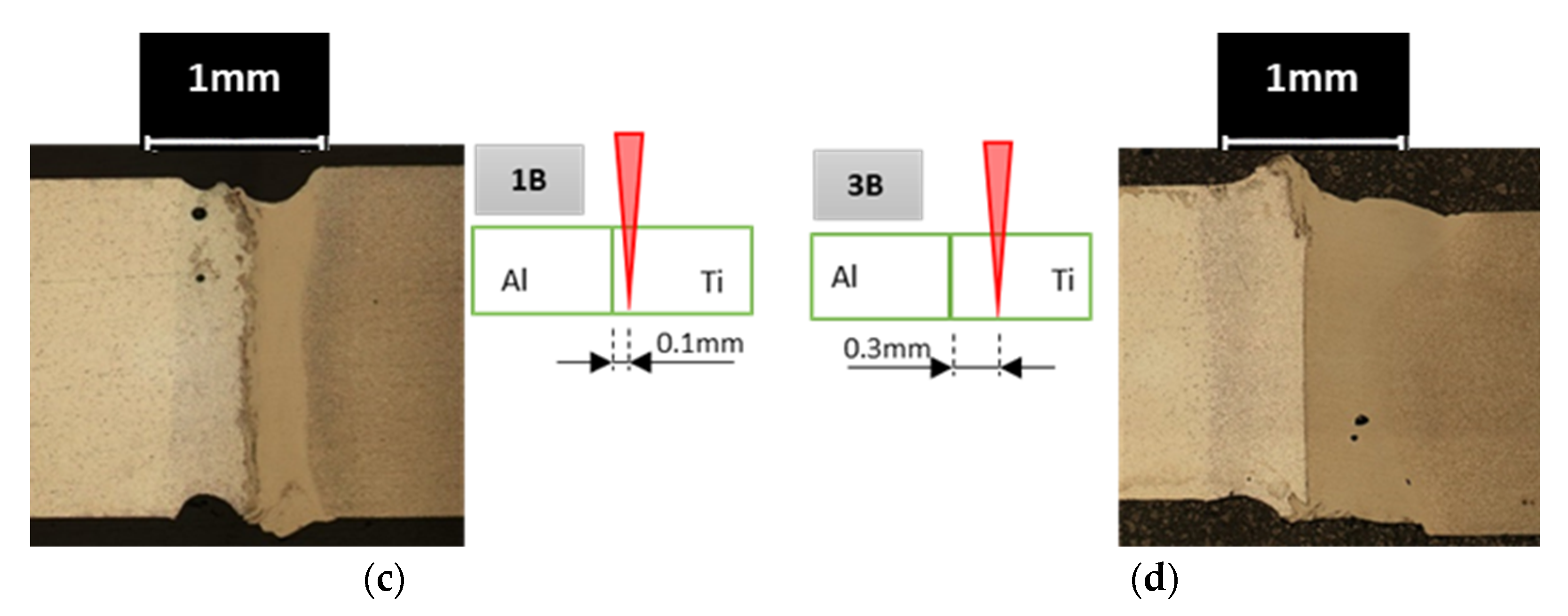
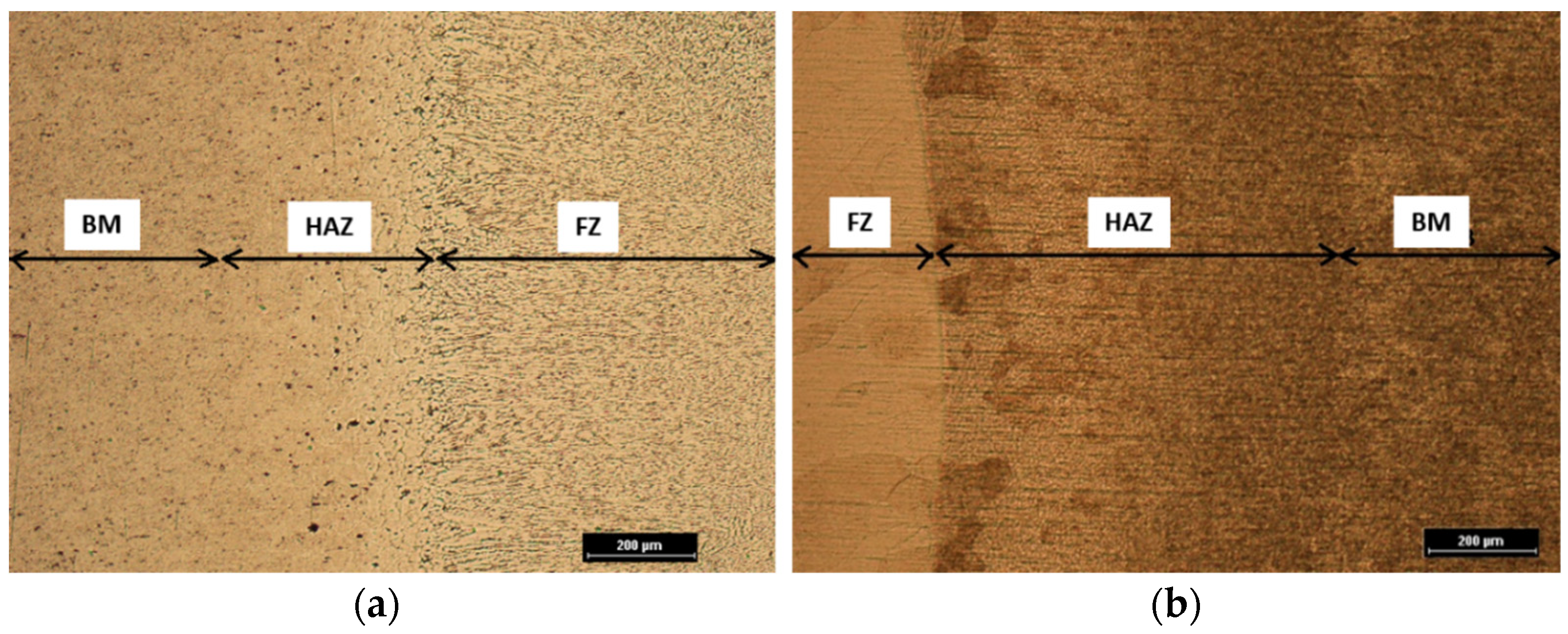
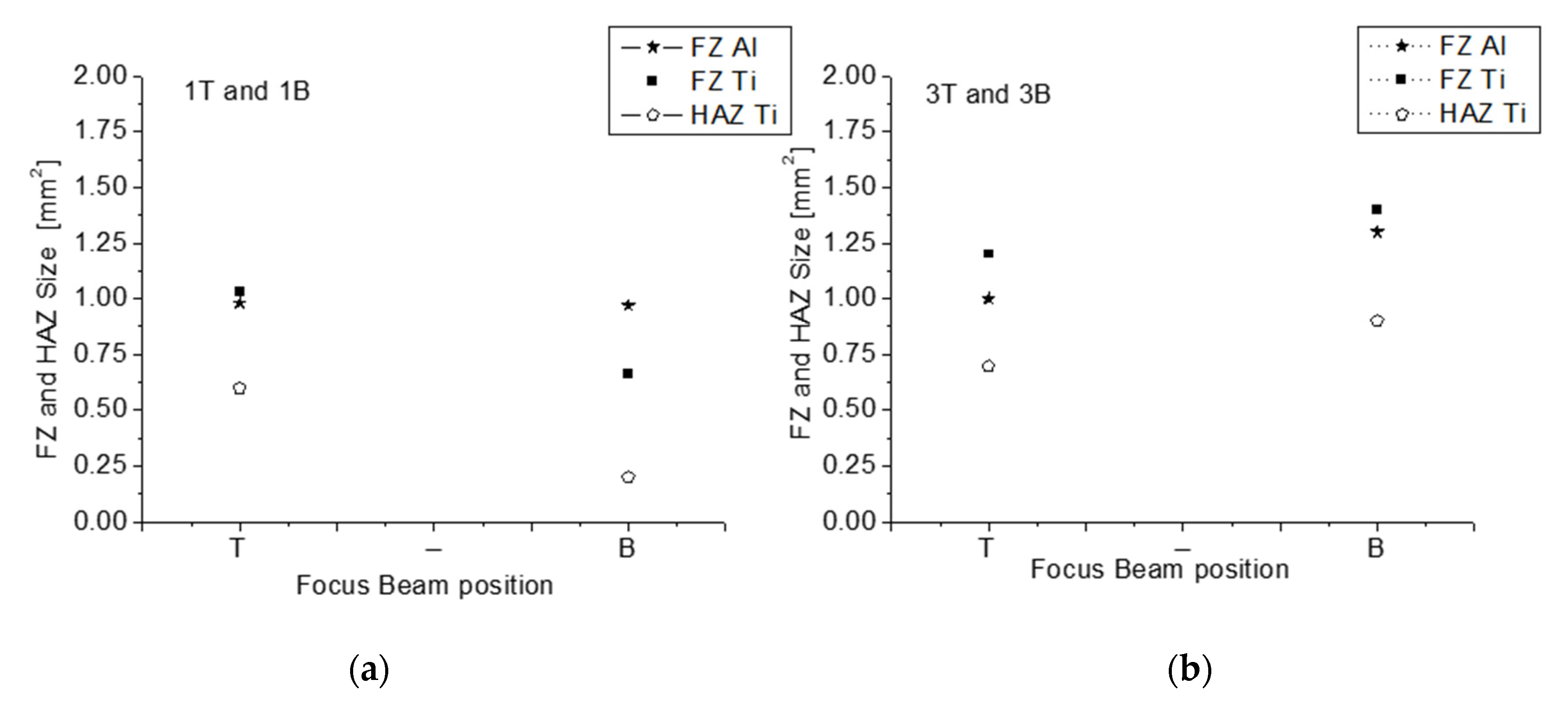
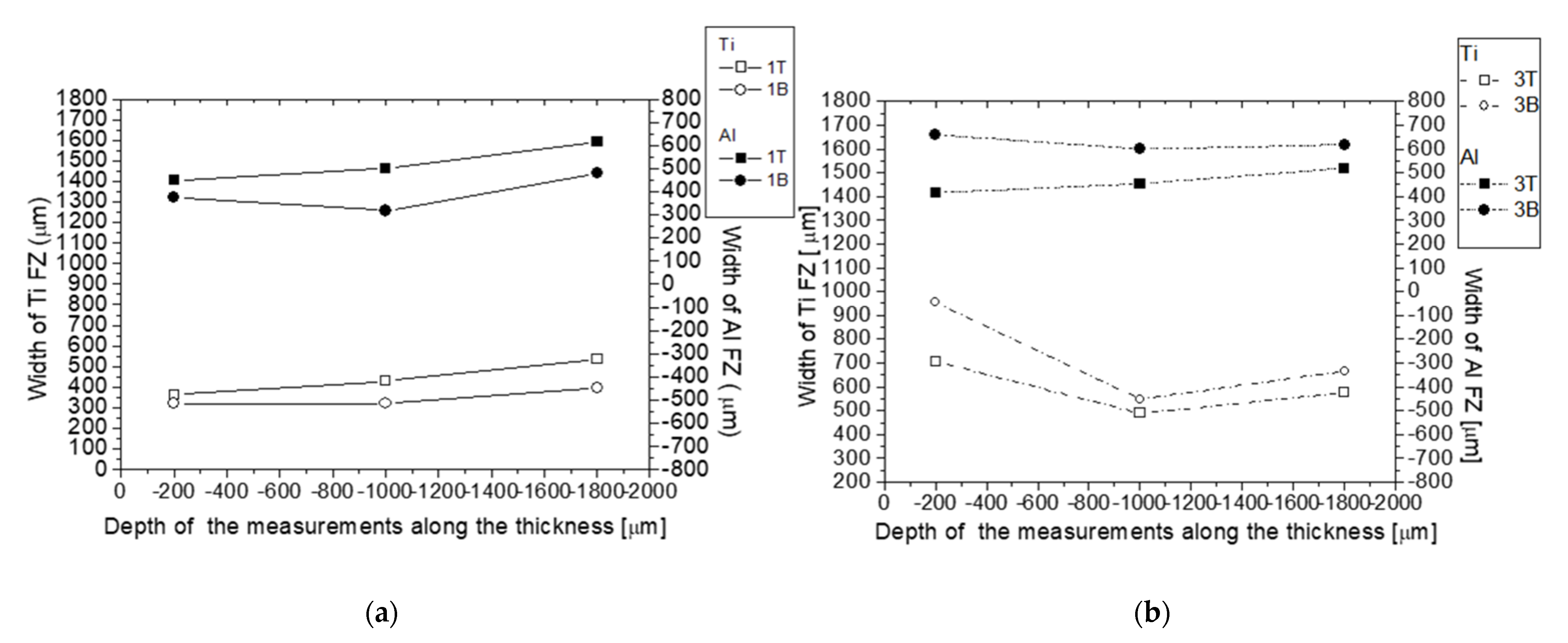
  • All the analyzed joints exhibit martensitic microstructure in the Ti fused zone and partially martensitic microstructure in Ti heat-affected zone. The Al fused zone was columnar dendritic. The size of those zones decreased with decreasing laser offset. The negative defocusing strengthens the effect of the laser offset by decreasing the size of the fused zones as the laser offset decreases and by increasing the size of the fused zones as the laser offset increases. Therefore, the highest size was observed for the joint 3B. Specifically, the fusion zone size for the 3B weld was close to 1.4 mm2 for both Al and Ti size.
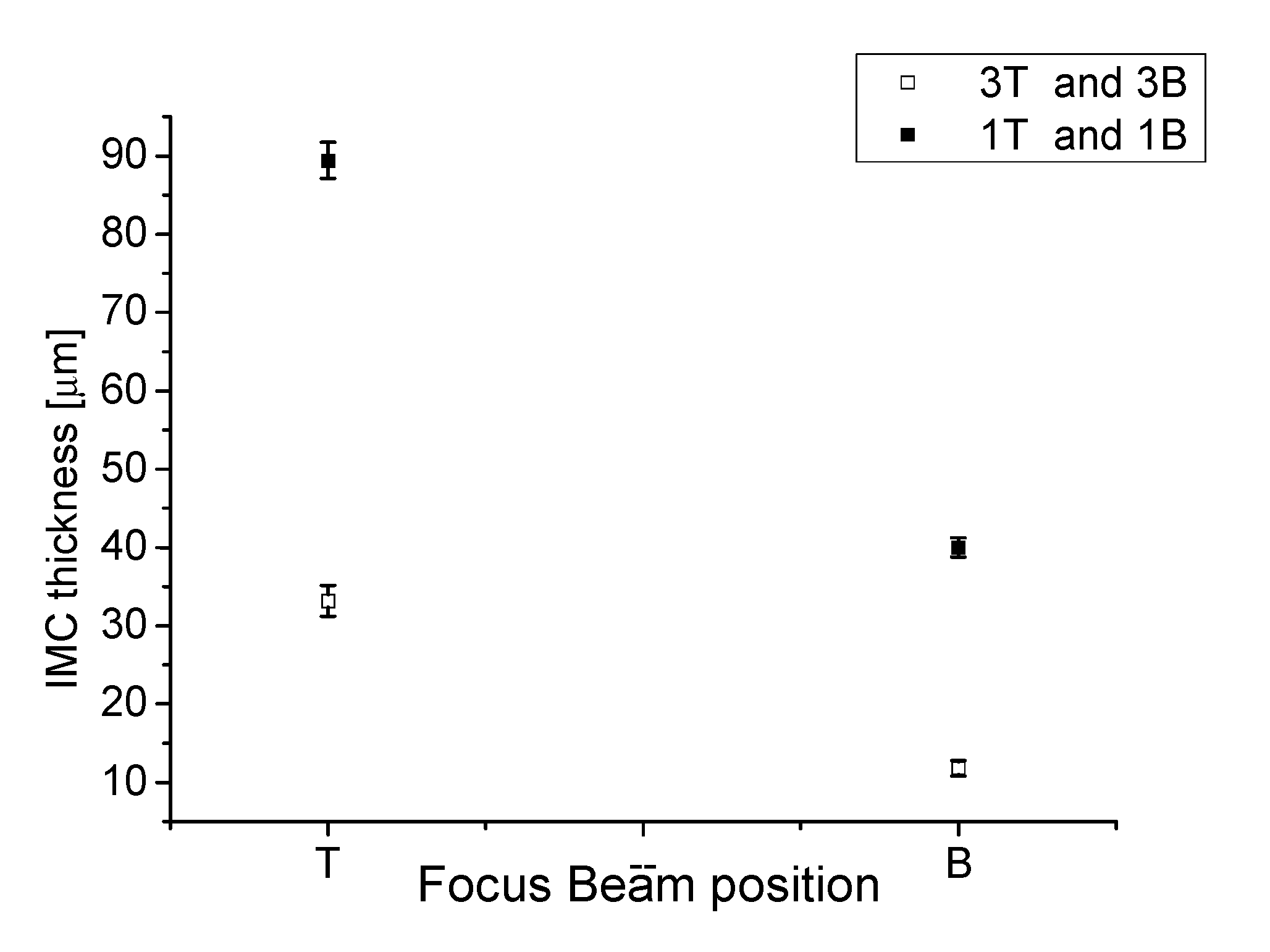
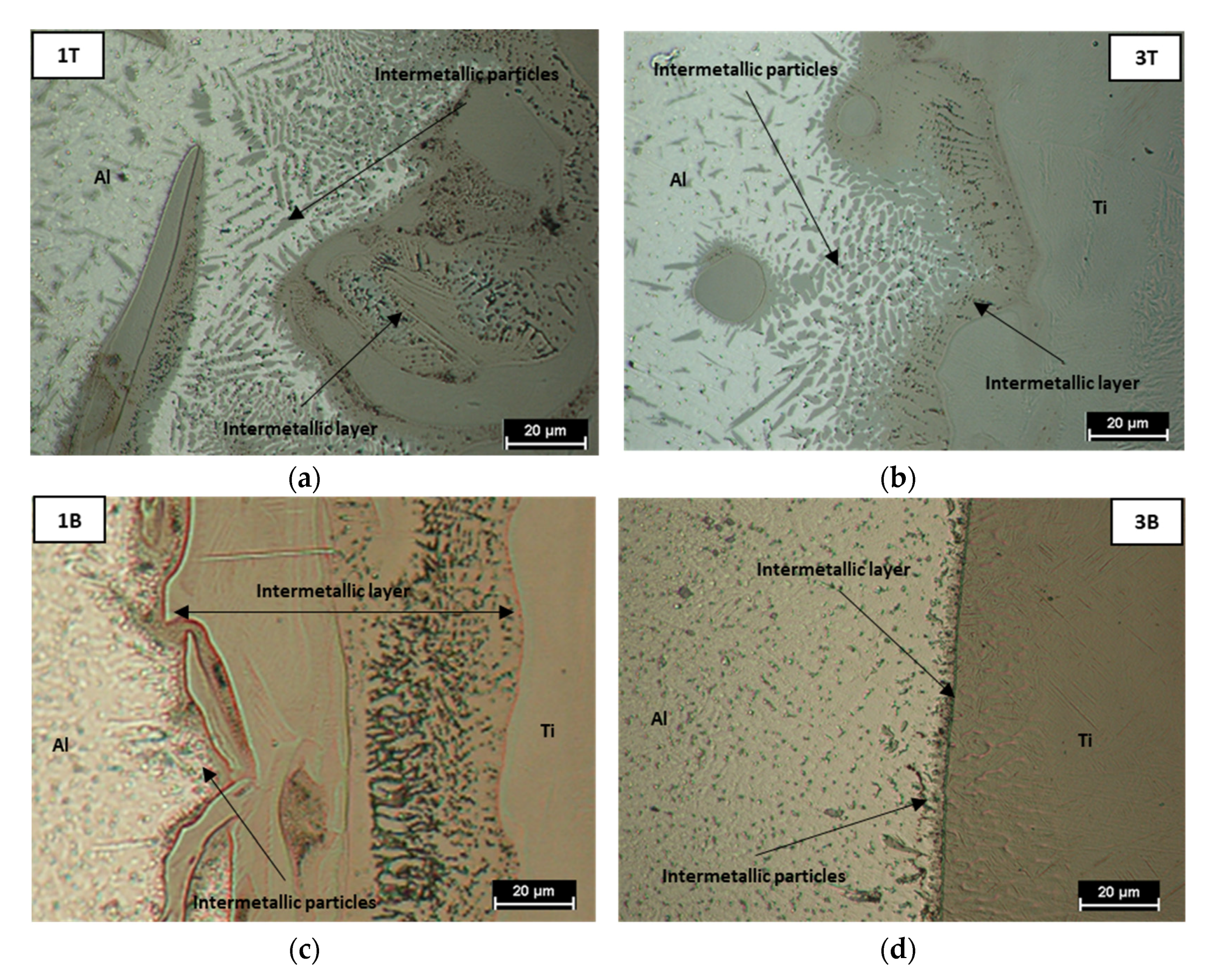
  • The thickness and shape of the intermetallic layer, as well as the number of the intermetallic particles, varied with both defocusing and the laser offset. The layer was flatter and less thick in the case of negative defocusing and laser offset increased due to the lower peak temperature at the interface and reduced mixing. Therefore, the lowest size, equal to 12 μm, was found in the 3B joint. For the same reason, the amount of particles, highest at the top of all the joints, also decreased with negative defocusing and increased with laser offset.
  • The hardness measurements executed in the focus (1T, 3T) and defocusing point (1B,3B) indicated that negative defocusing reduces the hardness, imposing a lower cooling rate (due to lower energy density) and consequent microstructure coarsening. With increasing laser offset, the effect of Ti heat conductivity mitigated the role of beam energy density. Consequently, the gap in hardness between joint 3T and 3B (equal to 50 HV) was less significant as compared to that of joint 1T and 1B (equal to 100 HV).
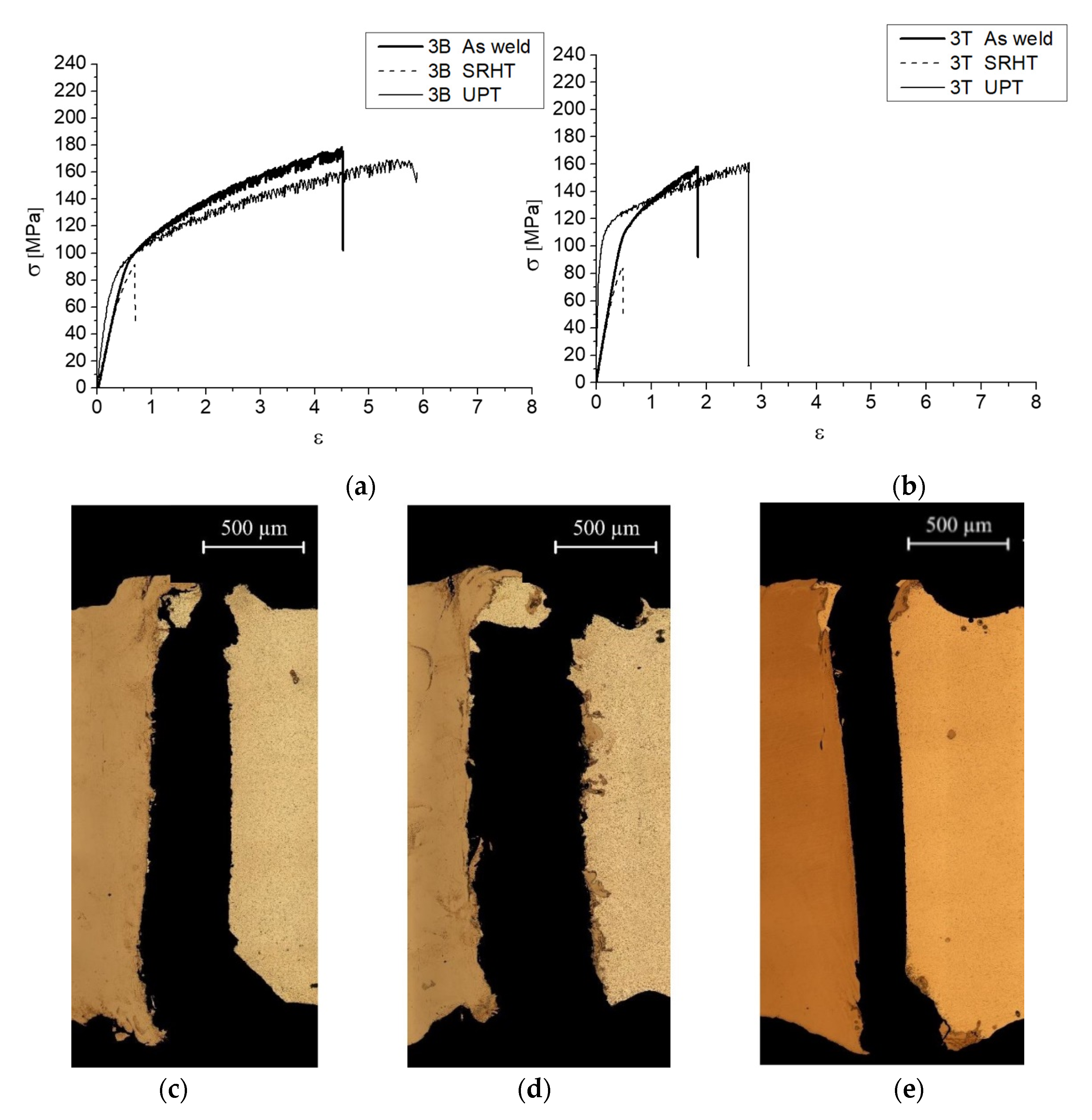
  • Joint 3B exhibited the best tensile performances, with an ultimate tensile stress close to 173 MPa and strain to fracture equal to 4.5%. This behavior is justified by the lowest amount of intermetallic compound and the lowest gap of hardness values at the Al–Ti interface, as shown in the previous results.
  • The stress relief heat treatment at 530 °C for 2 h significantly hardens the Ti side and induces the growth of the intermetallic compounds. The average growth of IMCL was equal to 2.60 ± 0.6 μm and 1.30 ± 0.3 μm, respectively, for the 3T and 3B joints. The microstructure evolution induced by the heat treatment leads to both ductility and strength reduction.
  • The UPT-treated welds are characterized by higher elastic modulus and fracture strain with respect to the welded ones, probably due to the reduction of porosity. The fracture strain of the 3B joint was equal to 4.5% in the weld state and 5.8% after UPT. The ultimate tensile strength of UPT-treated and welded samples do not differ significantly, but work hardening behavior is different. Further studies are necessary to define the relationship between mechanical properties and UPT treatment for Al/Ti dissimilar joints and, possibly, introduce further improvements.
  • The results of the electrochemical measurements indicate that the corrosion susceptibility of the welds is enhanced by means of UPT treatment.

Author Contributions

Conceptualization, P.L.; methodology, P.L.; validation, P.L.; formal analysis, P.L.; investigation, P.L., S.D., R.N., C.M., A.T.; resources, G.C.; data curation, P.L.; writing—original draft preparation, P.L.; writing—review and editing, P.L., R.N., C.M., S.D.; visualization, P.L.; supervision, P.L. All authors have read and agreed to the published version of the manuscript.

Funding

This research received no external funding.

Institutional Review Board Statement

Not applicable.

Informed Consent Statement

Not applicable.

Data Availability Statement

The data presented in this study are available on request from the corresponding author.

Conflicts of Interest

The authors declare no conflict of interest.

References

  1. Jiang, P.; Chen, R. Research on interfacial layer of laser-welded aluminum to titanium. Mater. Charact. 2019, 154, 264–268. [Google Scholar] [CrossRef]
  2. Martinsen, K.; Hu, S.J.; Carlsond, B.E. Joining of dissimilar materials. CIRP Annals 2015, 64, 679–699. [Google Scholar] [CrossRef] [Green Version]
  3. Vaidya, W.V.; Horstmann, M.; Ventzke, V.; Petrovski, B.; Koçak, M.; Kocik, R. Improving interfacial properties of a laser beam welded dissimilar joint of aluminum AA6056 and titanium Ti6Al4V for aeronautical applications. J. Mater. Sci. 2010, 45, 6242–6254. [Google Scholar] [CrossRef] [Green Version]
  4. Quazia, M.M.; Ishaka, M.; Fazalb, M.A.; Arslanc, A.; Rubaieeb, S.; Qabane, A.; Aimana, M.H.; Sultanf, T.; Alig, M.M.; Manladanh, S.M. Current research and development status of dissimilar materials laser welding of titanium and its alloys. Opt. Laser Technol. 2020, 126, 106090. [Google Scholar] [CrossRef]
  5. Malikova, A.; Vitoshkina, I.; Orishicha, A.; Filippova, A.; Karpova, E. Effect of the aluminum alloy composition (Al-Cu-Li or Al-Mg-Li) on structure and mechanical properties of dissimilar laser welds with the Ti-Al-V alloy. Opt. Laser Technol. 2020, 126, 106135. [Google Scholar] [CrossRef]
  6. Malikova, A.; Vitoshkina, I.; Orishicha, A.; Filippova, A.; Karpova, E. Microstructure and mechanical properties of laser welded joints of Al-Cu-Li and Ti-Al-V alloys. J. Manuf. Process. 2020, 53, 201–212. [Google Scholar] [CrossRef]
  7. Xue, X.; Wu, X.; Liao, J. Hot-cracking susceptibility and shear fracture behavior of dissimilar Ti6Al4V/AA6060 alloys in pulsed Nd:YAG laser welding. Chin. J. Aeronaut. 2020, 34, 375–386. [Google Scholar] [CrossRef]
  8. Wang, Z.; Shen, J.; Hu, S.; Wang, T.; Bu, X. Investigation of welding crack in laser welding-brazing welded TC4/6061nd TC4/2024 dissimilar butt joints. J. Manuf. Process. 2020, 60, 54–60. [Google Scholar] [CrossRef]
  9. Messler, R.W., Jr. Principles of Welding: Processes, Physics, Chemistry, and Metallurgy; Wiley: Hoboken, NJ, USA, 1999. [Google Scholar]
  10. Kou, S. Welding Metallurgy, 2nd ed.; Wiley: Hoboken, NJ, USA, 2003. [Google Scholar]
  11. Metelkova, J.; Kinds, Y.; Kempen, K.; de Formanoir, C.; Witvrouw, A.; Hooreweder, B.V. On the influence of laser defocusing in Selective Laser Melting of 316L. Addit. Manuf. 2018, 23, 161–169. [Google Scholar] [CrossRef]
  12. Ferro, P.; Berto, F.; Bonollo, F.; Romanina, L.; Salemic, G. Post welding heat treatment improving mechanical properties on Ti-6Al-4V. Procedia Struct. Integr. 2020, 26, 11–19. [Google Scholar] [CrossRef]
  13. Leo, P.; D’Ostuni, S.; Casalino, G. Low temperature heat treatments of AA5754-Ti6Al4V dissimilar laser welds: Microstructure evolution and mechanical properties. Opt. Laser Technol. 2018, 100, 109–118. [Google Scholar] [CrossRef]
  14. Li, P.; Lei, Z.; Zhang, X.; Chen, Y. Effects of a post-weld heat treatment on the microstructure and mechanical properties of dual-spot laser welded-brazed Ti/Al butt joints. J. Manuf. Process. 2021, 61, 492–506. [Google Scholar] [CrossRef]
  15. Lazurenko, D.V.; Bataev, I.A.; Mali, V.I.; Bataev, A.A.; Maliutina, I.N.; Lozhkin, V.S.; Esikov, A.M.; Jorge, J. Explosively welded multilayer Ti-Al composites: Structure and transformation during heat treatment. Mat. Des. 2016, 102, 122–130. [Google Scholar] [CrossRef]
  16. Xu, L.; Cui, Y.Y.; Hao, Y.L.; Yang, R. Growth of intermetallic layer in multi-laminated Ti/Al diffusion couples. Mat. Sci. Eng. A 2006, 435, 638–647. [Google Scholar] [CrossRef]
  17. Malaki, M.; Ding, H. A review of ultrasonic peening treatment. Mat. Des. 2015, 87, 1072–1086. [Google Scholar] [CrossRef]
  18. Tian, Y.; Shen, J.; Hu, S.; Liang, Y.; Bai, P. Effects of ultrasonic peening treatment on surface quality of CMT-welds of Al alloys. J. Mat. Proc. Tech. 2018, 254, 193–200. [Google Scholar] [CrossRef]
  19. Hacini, L.; Van Lê, N.; Bocher, P. Evaluation of Residual Stresses Induced by Robotized Hammer Peening by the Contour. Method. Exp. Mech. 2009, 49, 775–783. [Google Scholar] [CrossRef]
  20. Hacini, L.; Van Lê, N.; Bocher, P. Effect of impact energy on residual stresses induced by hammer peening of 304 L plates. J. Mater. Process. Technol. 2008, 208, 542–548. [Google Scholar] [CrossRef]
  21. Mordyuk, B.N.; Karasevskaya, O.P.; Prokopenko, G.I. Structurally induced enhancement in corrosion resistance of Zr–2.5%Nb alloy in saline solution by applying ultrasonic impact peening. Mater. Sci. Eng. 2013, 559, 453–461. [Google Scholar] [CrossRef]
  22. Yanga, B.; Tana, C.; Zhaob, Y.; Wua, L.; Chena, B.; Songa, X.; Zhaoa, H.; Fenga, J. Influence of ultrasonic peening on microstructure and surface performance of laser-arc hybrid welded 5A06 aluminum alloy joint. J. Mater. Res. Technol. 2020, 9, 9576–9587. [Google Scholar] [CrossRef]
  23. Statnikov, E.S.; Muktepavel, V.O.; Blomqvist, A. Comparison of Ultrasonic Impact Treatment (UIT) and Other Fatigue Life Improvement Methods. Weld. World. 2002, 46, 20–32. [Google Scholar] [CrossRef]
  24. Ooi, S.W.; Garnham, J.E.; Ramjaun, T.I. Review: Low transformation temperature weld filler for tensile residual stress reduction. Mater. Des. 2014, 56, 773–781. [Google Scholar] [CrossRef]
  25. Lixing, H.; Dongpo, W.; Wenxian, W.; Yufeng, Z. Ultrasonic Peening and Low Transformation Temperature Electrodes used for Improving the Fatigue Strengthof Welded Joints. Weld. World. 2004, 48, 34–39. [Google Scholar] [CrossRef]
  26. Mordyuk, B.N.; Prokopenko, G.I.; Milman, Y.V.; Iefimov, M.O.; Sameljuk, A.V. Enhanced fatigue durability of Al–6Mg alloy by applying ultrasonic impact peening: Effects of surface hardening and reinforcement with AlCuFe quasicrystalline particles. Mater. Sci. Eng. A 2013, 563, 138–146. [Google Scholar] [CrossRef]
  27. Polmear, I.J. Light Alloys: Metallurgy of the Light Metals; Butterworth Heinemann: Oxford, UK, 1995. [Google Scholar]
  28. Mondolfo, L.F. Aluminium Alloys: Structure and Properties; Butterworth: Oxford, UK, 1976. [Google Scholar]
  29. Porter, D.A.; Easterling, K.E. Phase Transformations in Metals and Alloys; Chapman & Hall: London, UK, 1992. [Google Scholar]
  30. Smith, W.F. Structure and Properties of Engineering Alloys; McGraw-Hill: New York, NY, USA, 1992. [Google Scholar]
  31. D’Ostuni, S.; Leo, P.; Casalino, G. FEM Simulation of Dissimilar Aluminum Titanium Fiber Laser Welding Using 2D and 3D Gaussian Heat Sources. Metals 2017, 7, 307. [Google Scholar] [CrossRef] [Green Version]
  32. Maisonnette, D.; Suery, M.; Nelias, D.; Chaudet, P.; Epicier, T. Effects of heat treatments on the microstructure and mechanical properties of a AA6061 aluminium alloy. Mat. Sci. Eng. 2011, 528.6, 2718–2724. [Google Scholar] [CrossRef] [Green Version]
  33. Kabir, A.S.H.; Cao, X.; Gholipour, J.; Wanjara, P.; Cuddy, J. Effect of Postweld Heat Treatment on Microstructure, Hardness, and Tensile Properties of Laser-Welded Ti-6Al-4V. Met. Mat. Trans. A 2012, 43, 4171–4184. [Google Scholar] [CrossRef] [Green Version]
  34. Chawla, N.; Deng, X. Microstructure and mechanical behavior of porous sintered steels. Mater. Sci. Eng. A 2005, 390, 98–112. [Google Scholar] [CrossRef]
  35. Zhoua, J.; Suna, Z.; Kanoutea, P.; Retrainta, D. Reconstruction of residual stress and work hardening and their effects on the mechanical behaviour of a shot peened structure. Mech. Mater. 2018, 127, 100–111. [Google Scholar] [CrossRef]
  36. Muna, K.; Abbass, K.S.H.; Abbas, S.A. Study of Corrosion Resistance of Aluminum Alloy AA6061/SiC Composites in 3.5% NaCl Solution. Int. J. Mater. Mech. Manuf. 2015, 3, 31–35. [Google Scholar]
  37. Fahimpour, V.; Sadrnezhaad, S.K.; Karimzadeh, F. Corrosion behavior of aluminum AA6061 alloy joined by friction stir welding and gas tungsten arc welding methods. Mater. Des. 2012, 39, 329–333. [Google Scholar] [CrossRef]
Figure 1. Cross section of the joints 1T (a), 3T (b), 1B (c) and 3B (d) coupled with the schemes of the process.
Metals 11 01257 g001aMetals 11 01257 g001b
Figure 2. Optical micrographs of the AA6061 BM (a), Ti-6Al-4V BM (b), AA6061 FZ (c) and Ti-6Al-4V FZ (d).
Metals 11 01257 g002
Figure 3. Optical micrographs showing microstructural evolution in the Al side (a) and Ti side (b).
Metals 11 01257 g003
Figure 4. IMCL thickness size for joints 1T and 1B and joints 3T and 3B as function of the focus beam position.
Metals 11 01257 g004
Figure 5. Intermetallic layer at a half of thickness in the welds cross sections of joints 1T (a), 1B (c), 3T (b) and 3B (d).
Metals 11 01257 g005
Figure 6. FZ and HAZ size for joints 1T and 1B (a) and joints 3T and 3B (b). Considering both focused (T) and defocused beam (B), the joints 1T and 1B (a) are characterized by a lower size of the FZ with respect to joints 3T and 3B (b).
Metals 11 01257 g006
Figure 7. Width of the FZ side along the thickness for joints 1T and 1B (a) and joints 3T and 3B (b): the size of joint 3B along the thickness is always higher than the size of 3T joint (b), while the opposite is true for joints 1T and 1B (a).
Metals 11 01257 g007
Figure 8. Distribution of IMC particles as function of particles area in 1T, 1B, 3T and 3B joints.
Metals 11 01257 g008
Figure 9. IMC particles distribution along the thickness of joints 1T and 1B.
Metals 11 01257 g009
Figure 10. IMC particles distribution along the thickness of joints 3T and 3B.
Metals 11 01257 g010
Figure 11. Micro hardness profile as a function of distance from the weld interface at 200 and 1800 µm from upper surface for 1T and 1B weld (a) and 3T and 3B welds (b).
Metals 11 01257 g011
Figure 12. Micro hardness profile as a function of distance from the weld interface at a half of thickness for joints before and after SRHT.
Metals 11 01257 g012
Figure 13. Optical micrographs before (a,b) and after (c,d) SRHT for welds 3 T (a,c) and 3B (b,d).
Metals 11 01257 g013
Figure 14. Scanning electron micrographs before (a,b) and after (c,d) SRHT for 3T weld at 7500× (a,c) and 10,000× (b,d). 3T sample microstructure after SRHT at 2000× and 7500× with circled the zone of EDS investigation (e,f), together with the points of analysis (f).
Metals 11 01257 g014aMetals 11 01257 g014b
Figure 15. Tensile curves for joints 3B (a) and 3T (b) as welded, after SRHT and after UPT. Fractured cross section of B sample after tensile test in as welded state (c), after UPT (d) and after SRHT (e).
Metals 11 01257 g015
Figure 16. (a) Open circuit potential and (b) potentiodynamic polarization curves of AA6061 before and after UPT, 3B joint before and after UPT, Ti-6Al-4V samples tested in 3.5% NaCl solution.
Metals 11 01257 g016
Figure 17. Pictures of corroded windows of the samples and optical micrographs of one edge of the corrosion window (circled in the pictures) for Al sample before UPT (a), Al sample after UPT (c), 3B weld before UPT (b) and 3B weld after UPT (d).
Metals 11 01257 g017
Table 1. AA6061 alloy chemical composition.
SiFeCuMnMgCrZnTiAl
0.400.400.100.502.6–3.60.30.20<0.15bal.
Table 2. Ti6Al4V alloy chemical composition.
CFeN2O2AlVH2TiC
<0.08<0.25<0.05<0.25.53.5<0.03bal.<0.08
Table 3. Average results coming from tensile test of two specimens for joints 1T, 1B, 3T, 3B.
JointsYield Stress [MPa]Ultimate Tensile Stress [Mpa]Strain [%]
1T95 ± 3110.2 ± 61.4 ± 0.3
1B88 ± 4100.0 ± 31.2 ± 0.2
3T118 ± 5158.1 ± 81.8 ± 0.4
3B98 ± 4172.7 ± 84.5 ± 0.9
Table 4. EDS result on particle (point 1) and aluminum matrix (point 2) shown in Figure 14f.
Elements [at%]Point 1 (Particle)Point 2 (Matrix)
Al72.2 ± 2.685.4 ± 3.0
Ti26.9 ± 1.010.7 ± 0.8
Table 5. Corrosion potential and corrosion current density extracted from potentiodynamic polarization curves reported in Figure 16b.
MaterialEcorricorr
V vs. Ag/AgClμAχμ−2
AA6061 before UPT−0.71911.05
AA6061 after UPT−0.6036.22
Ti-6Al-4V−0.2090.26
3B weld before UPT−0.72416.12
3B weld after UPT−0.6179.28
Publisher’s Note: MDPI stays neutral with regard to jurisdictional claims in published maps and institutional affiliations.

