Article

Oxidation Behavior of Maraging 300 Alloy Exposed to Nitrogen/Water Vapor Atmosphere at 500 °C

by
Mauro Andres Cerra Florez
1,2,3,*,
Gemma Fargas Ribas
2,3,
Jorge Luiz Cardoso
1,
Antonio Manuel Mateo García
2,3,
Joan Josep Roa Rovira
2,3,
Moises Bastos-Neto
4,
Hamilton Ferreira Gomes de Abreu
1 and
Marcelo José Gomes da Silva
1
1
LACAM—Department of Metallurgical and Materials Engineering, Campus do Picí, Universidade Federal do Ceará, Bloco 729, Fortaleza 60440-554, Brazil
2
Center for Structural Integrity, Reliability and Micromechanics of Materials (CIEFMA), Department of Materials Science and Engineering, Escola d’Enginyeria de Barcelona Est, Universitat Politècnica de Catalunya, 08019 Barcelona, Spain
3
Barcelona Research Center in Multiscale Science and Engineering, Escola d’Enginyeria de Barcelona Est, Universitat Politècnica de Catalunya, 08019 Barcelona, Spain
4
Grupo de Pesquisa em Separações por Adsorção (GPSA)—Department of Chemical Engineering, Universidade Federal do Ceará, Fortaleza 60455-760, Brazil
*
Author to whom correspondence should be addressed.
Metals 2021, 11(7), 1021; https://doi.org/10.3390/met11071021
Submission received: 28 May 2021 / Revised: 9 June 2021 / Accepted: 23 June 2021 / Published: 24 June 2021
(This article belongs to the Special Issue Hot Oxidation and Corrosion of High Performance Metallic Alloys)

Abstract

:
Aging heat treatments in maraging steels are fundamental to achieve the excellent mechanical properties required in several industries, i.e., nuclear, automotive, etc. In this research, samples of maraging 300 alloy were aged using a novel procedure that combines different steps with two atmospheres (nitrogen and water vapor) for several hours. The oxidized surface layer was chemical, microstructural and micromechanically characterized. Due to the thermodynamic and kinetic conditions, these gases reacted and change the surface chemistry of this steel producing a thin iron-based oxide layer of a homogeneous thickness of around 500 nm. Within the aforementioned information, porosity and other microstructural defects showed a non-homogeneous oxide, mainly constituted by magnetite, nickel ferrite, cobalt ferrite, and a small amount of hematite in the more external parts of the oxide layer. In this sense, from a chemical point of view, the heat treatment under specific atmosphere allows to induce a thin magnetic layer in a mixture of iron, nickel, and cobalt spinel ferrites. On the other hand, the oxide layer presents an adhesive force 99 mN value that shows the capability for being used for tribological applications under sliding contact tests.

Graphical Abstract

1. Introduction

Maraging steels are known for their ultra-high-strength (UHS), which is attributed to the combination of a martensitic matrix with precipitates induced by an aging heat treatment, leading the material to be known as maraging steel [1]. In general, their fantastic properties are mainly attributed to their alloying elements. In this sense, these steels presents a solid solution of nickel (Ni), cobalt (Co), molybdenum (Mo), titanium (Ti), low carbon content (C), and aluminum (Al) [1,2]. In this sense, Ni ensures the formation of the martensitic phase [1]. Co is the main alloying element responsible for raising the martensitic transformation temperature. Furthermore, Co also increases the tensile strength and decreases Mo’s solubility in the martensitic phase, allowing the precipitation of intermetallic compounds during aging [2,3,4]. Mo is the main forming element of intermetallic compounds, such as Ni3Mo that leads to enhance the mechanical properties of maraging steels in terms of hardness [1,4]. Ti increases strength and with the presence of C induces the precipitation of different nature of carbides that decreases the strength of the maraging steel [4,5,6]. Finally, Al raises the tensile strength by hardening the martensitic phase [3,5,6].
The martensitic phase leads the maraging steels favorable conditions to nucleate and distribute the intermetallic compounds produced during aging at temperatures around 500 °C. In this sense, two different intermetallic compounds are produced, Ni3(Ti,Mo) and Fe2(Ti,Mo) with fine microstructure near the martensitic phase [1,7]. These phases permit improvement of the mechanical and magnetic properties and also the weldability.
Several decades ago, Klein et al. [8] characterized the formation and growth of oxides in Fe-18Ni-8.5Co and Fe-29Ni-17Co steels using air as well as superheated steam during the aging heat treatment at 485 °C for 3 h. In both steels for investigated atmospheres, the mainly formed oxide was magnetite (Fe3O4). On the other hand, Rezek et al. [9], investigated the aging effect on maraging steel grade 250 in superheated steam. Through this research, depending on the flow, several oxide layer thicknesses are induced. For thin layers, hematite and magnetite when the oxide layer is thin, whereas for thick oxide layer mainly is constituted by the magnetite phase. On the other hand, it is believed that at high gas flow, the oxide layer mainly may be constituted of spinel. Recently, Grayling et al. [10] investigated the oxide layer under air atmosphere at different times and temperatures and found two different trends being 480 °C the threshold between them. Furthermore, they found that oxidation kinetics occurs by the transport of reactant gas and metal species through the oxide layer.
It is well known that also the oxide layer induced in maraging steels under different atmospheres present a spinel microstructure composed of hematite (Fe2O3), nickel spinel (NiFe2O4) and cobalt spinel (CoFe2O4) [11,12,13].
Within the aforementioned information, the present research aims to induce an oxide layer with different nature depending on the atmosphere employed during the thermal treatment on maraging 300 alloy. Subsequently, the oxide layers will be chemically, microstructural and either mechanically investigated in terms of sliding contact tests.

2. Materials and Methods

2.1. Materials

The 18% nickel maraging 300 alloy (supplied by the Materials Characterization Laboratory-LACAM of the Universidade Federal do Ceará (Ceará, Brazil)) was cut using a metallographic saw to obtain a homogeneous samples of 20 mm × 10 mm × 5 mm (the chemical composition in wt % is summarized in Table 1). After that, the specimens were cleaned in ultrasound for 10 min and dried in pure air. The specimens investigated were solution annealed at 840 °C for 1 h and cooled in air (during 1 h approximately) to remove any effect of previous treatments and the mechanical cutting process of the samples. In order to obtain the desired surface roughness, the specimens were ground with SiC paper #2000 until reaching a mirror-like surface. The aging heat treatment were carried out in a tube furnace connected to a water vapor generator and N2 gas injection. The samples were placed in the furnace inside a quartz tube and heated up to 500 °C with N2 gas flow for 1 h. When the temperature reached was around 500 °C, the N2 gas was removed, and the temperature was kept constant using a combined atmosphere of water vapor and N2 for 3 h. The cooling process was taken inside the furnace with N2 gas flow to prevent the furnace oxygen entrance that could over-oxidize the different investigated specimens.

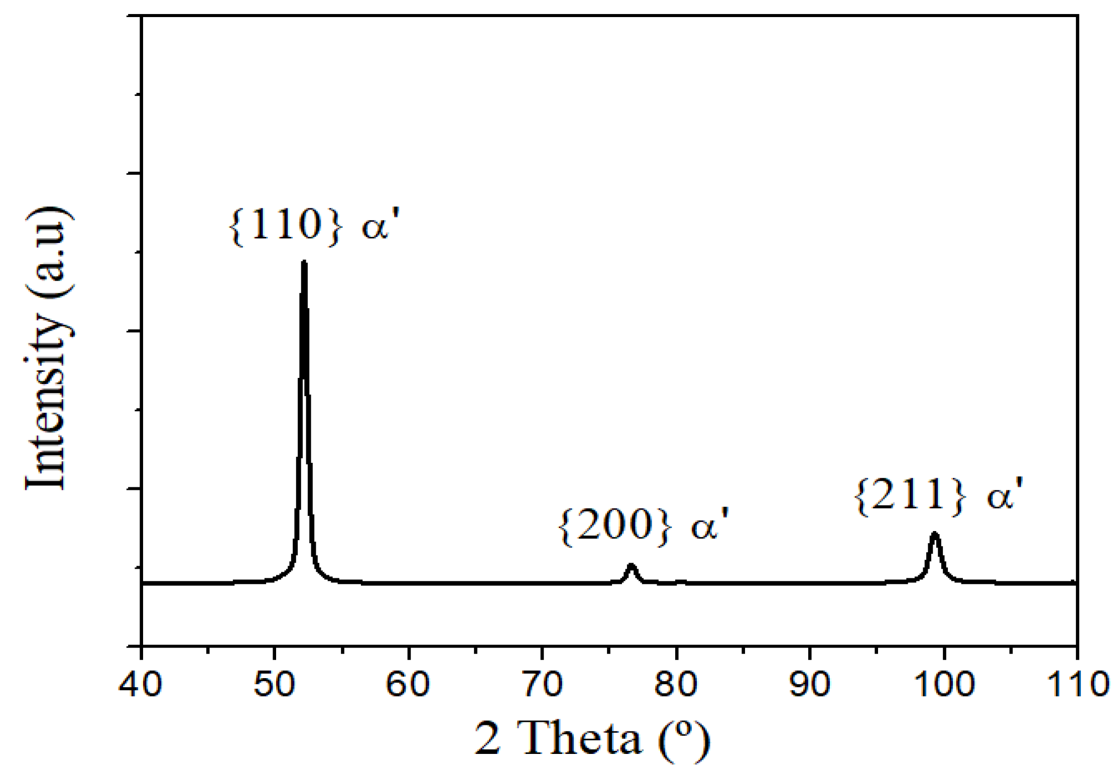
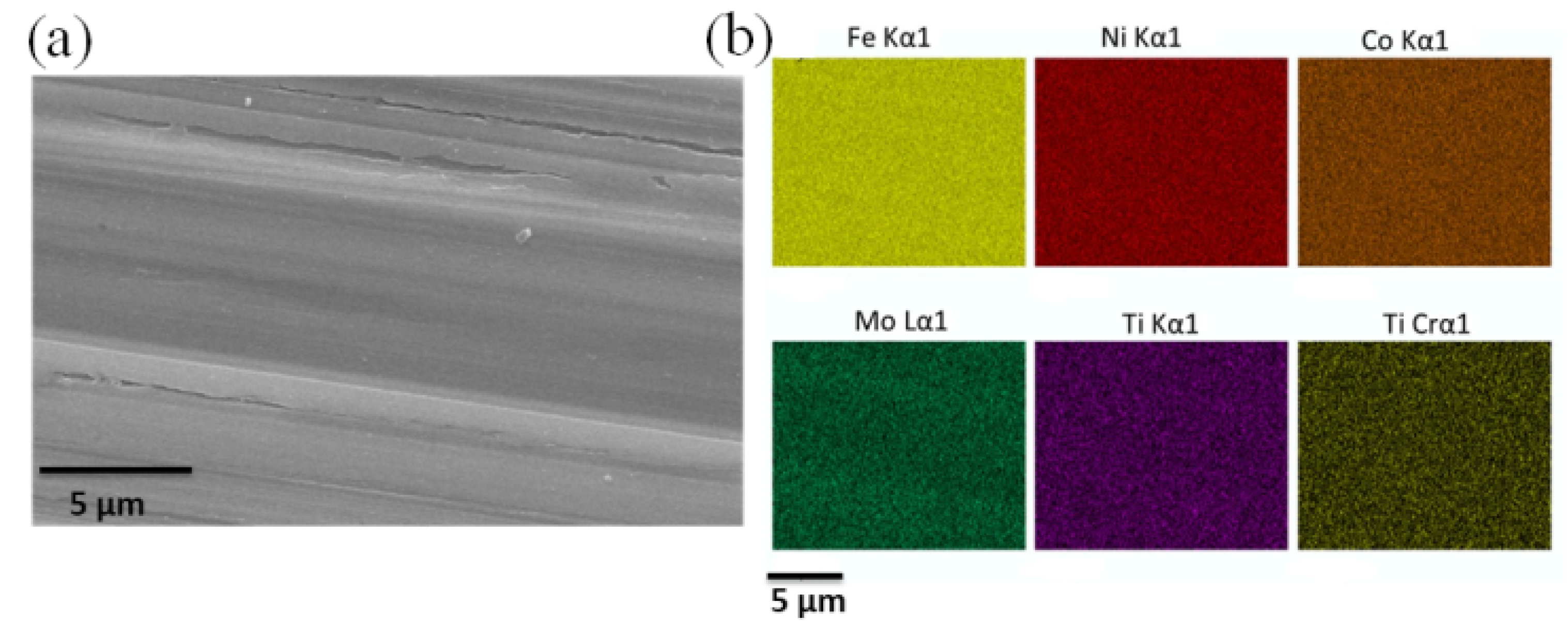
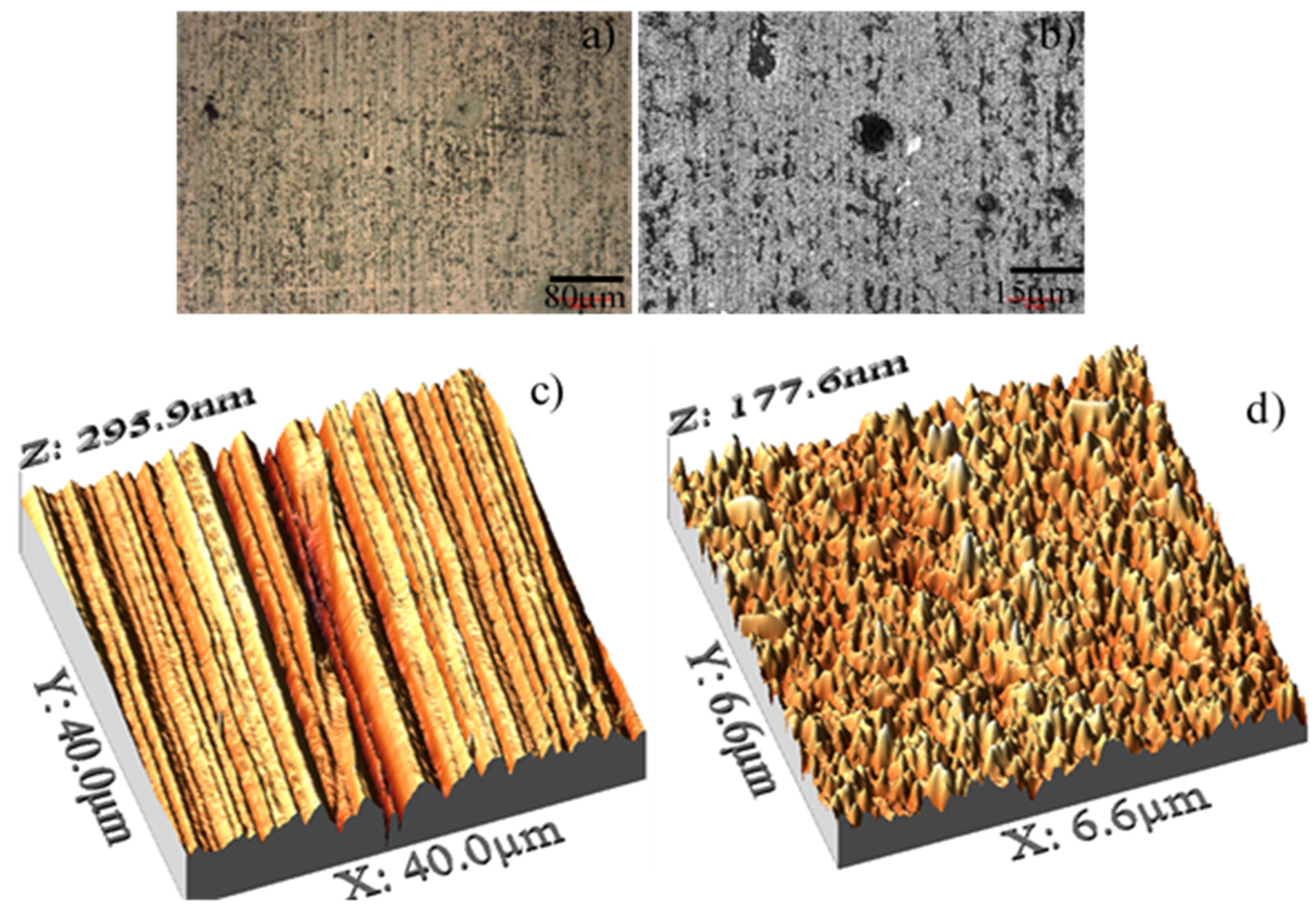
2.2. Microstructural Characterization

X-ray diffraction (XRD) analysis determines the phases present in the investigated steel. A Philips X’Pert X-ray diffractometer (Philips, Almelo, The Netherlands) with CoKα radiation and monochromator was used for the measurements. The angular parameter 2θ ranged from 10 to 90°, with an angular step of 0.02° per scan and counting time of 3 s. The voltage and current used were held constant and equals to 40 kV and 45 mA, respectively. The analysis of the XRD results was performed using the X’PertHighScore Plus® 4.9.0 software (Panalytical®, Almelo, The Netherlands). The distribution of the elements on the steel surface through element maps, was performed in the scanning electron microscope (SEM) Quanta 450 FEG-FEI (FEI company, Hillsboro, Oregon, EUA) with an energy-dispersive X-ray spectroscopy (EDS) detector.
In order to obtain a surface roughness, the specimens were ground and polished. Their roughness was observed by means of the atomic force microscope (AFM) Dimension D3100 (Veeco Instruments, Plainview, NY, USA) and subsequently treated by using the WSxM 5.0 software developed by Horcas et al. [14]. In order to perfectly assess the surface topography, several parameters were evaluated: including average roughness (Ra), maximum vertical height between the highest peak and the lowest valley (Rz), maximum peak height (Rp) and maximum valley depth (Rv). More information about the mathematical and physical definitions of these roughness parameters, as well as their respective equations, are available in [15,16,17].
The morphology of the oxides layers were characterized by laser scanning confocal microscopy (LSCM) Carl ZEISS LSM 800 (Carl Zeiss, Oberkochen, Germany). On the other hand the chemical composition and the oxide layer thickness were done by using scanning electron microscope (SEM) Quanta 450 FEG-FEI (FEI company, Hillsboro, Oregon, EUA) and the field emission scanning electron microscopy (FE-SEM) with focused ion beam (FIB) Zeiss Neon40 FE-SEM (Carl Zeiss NTS GmbH, Oberkochen, Germany) and analyzed by EDS. Furthermore, the chemical composition also were obtained through low angle (5°) X-ray diffraction (XRD, Philips X’Pert) by using the same operational conditions as mentioned above. The resulting spectrum were also analyzed by using the X´PertHighScore Plus® 4.9.0 software (Panalytical®, Almelo, The Netherlands) in order to quantify the different phases present in the oxide layer using the reference intensity ratio (RIR) [18,19]. Additionally, the oxide layer were analyzed by Raman Spectroscopy Renishaw inVia™ confocal (Renishaw, Gloucestershire, UK) with a Neon Laser (λ ~ 532 nm) and the obtained measures were treated by using WIRETM 4.4 software (Renishaw, Gloucestershire, UK).

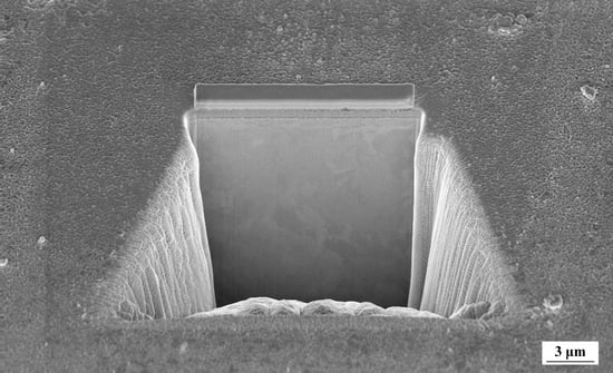
2.3. Sliding Properties

Nano-scratch tests were made with the same Nanoindenter XP (MTS) (Nanomechanics, Inc., Oak Ridge, TN, USA) that allows lateral force measurements. A Berkovich indenter was used to scratch the surface under increasing linearly up to a maximum load of 100 mN, at a velocity of 10 μm/s along 500 μm of a total scratch length. Three different scratches per specimens were performed in order to get the homogeneity of the oxide layer. The distance between them was held constant and equal to 500 μm to avoid overlapping effects. The scratches marks were observed by using the FIB/FE-SEM Zeiss Neon40 FE-SEM (Carl Zeiss NTS GmbH, Oberkochen, Germany).

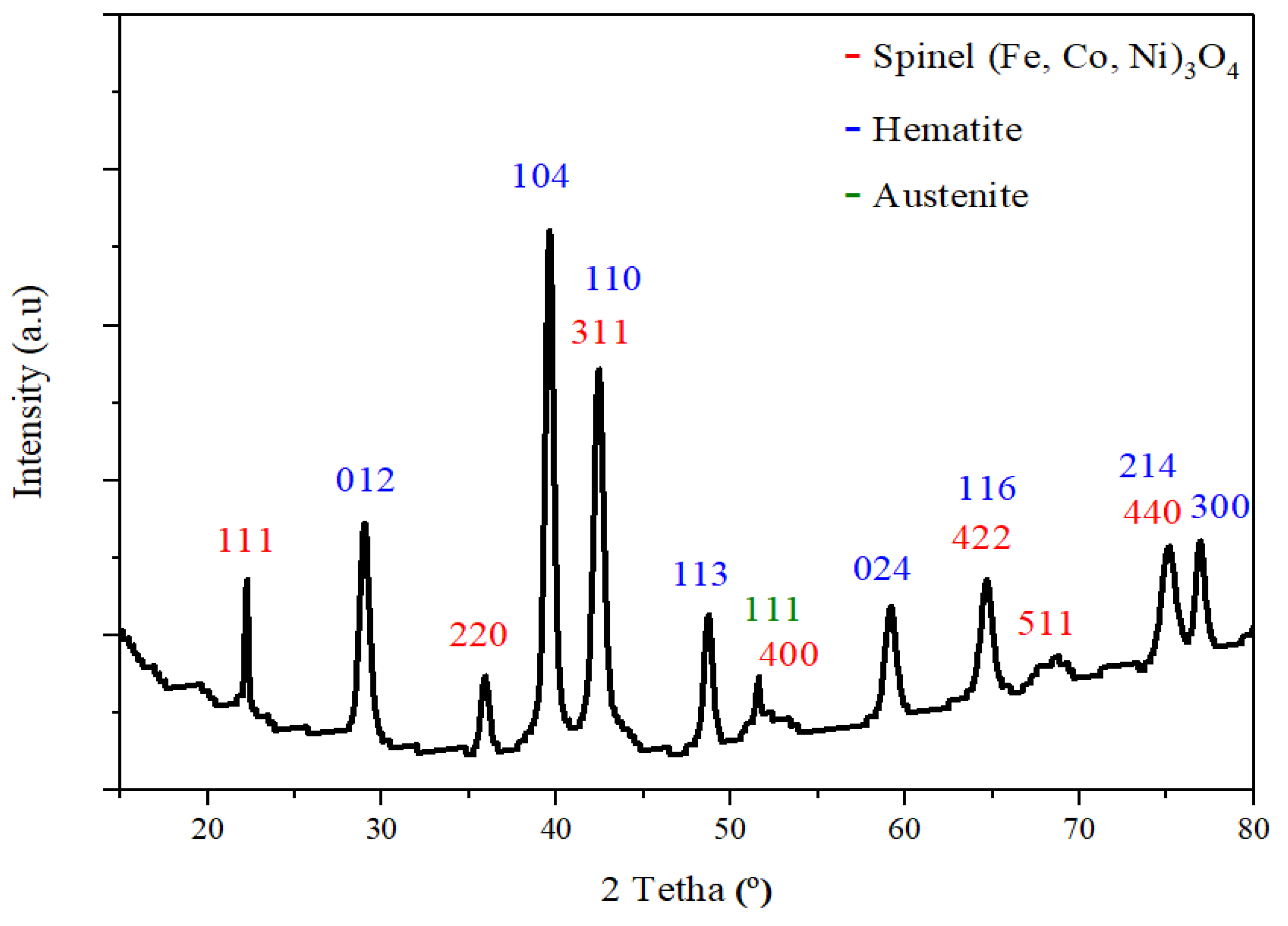
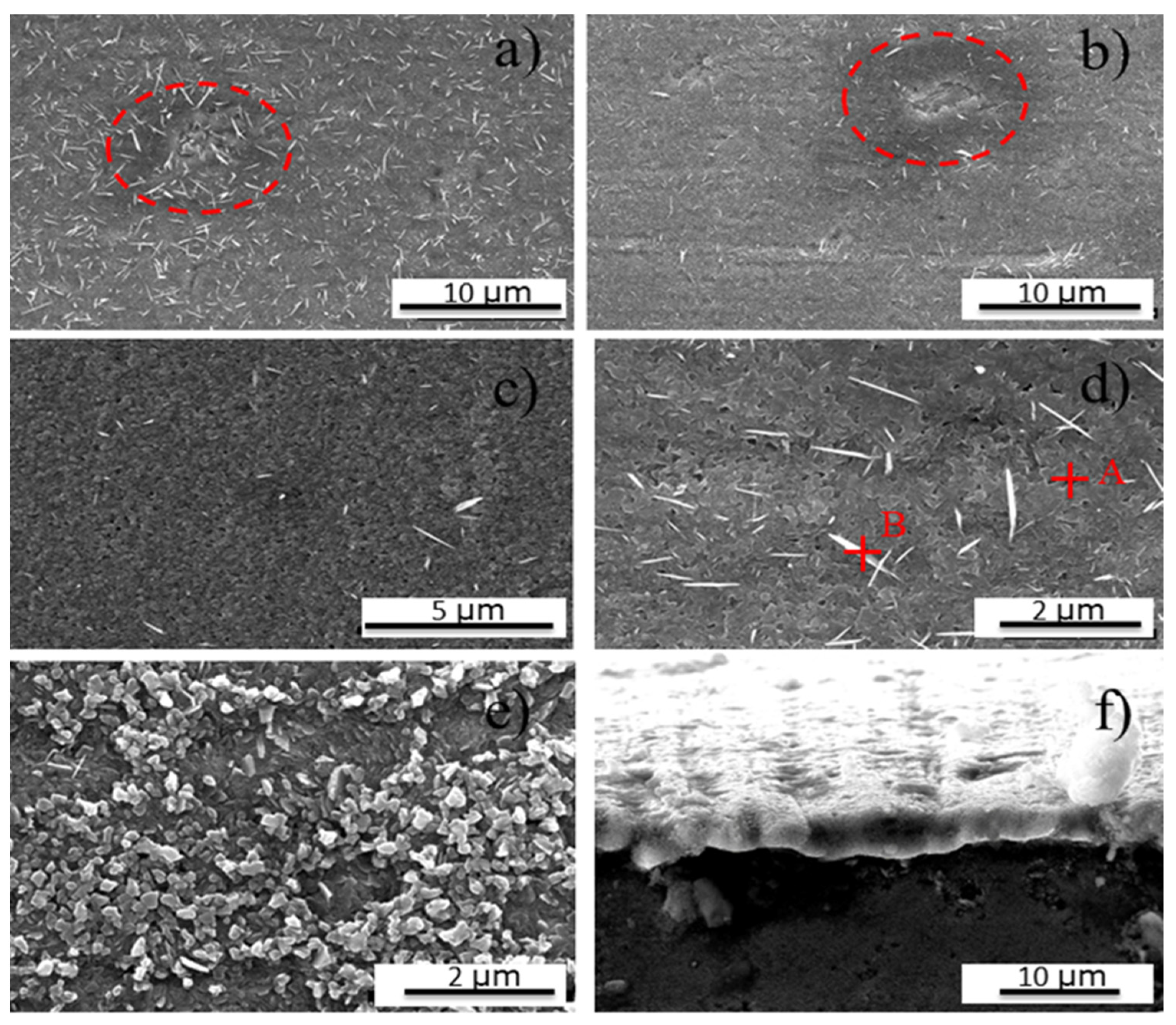
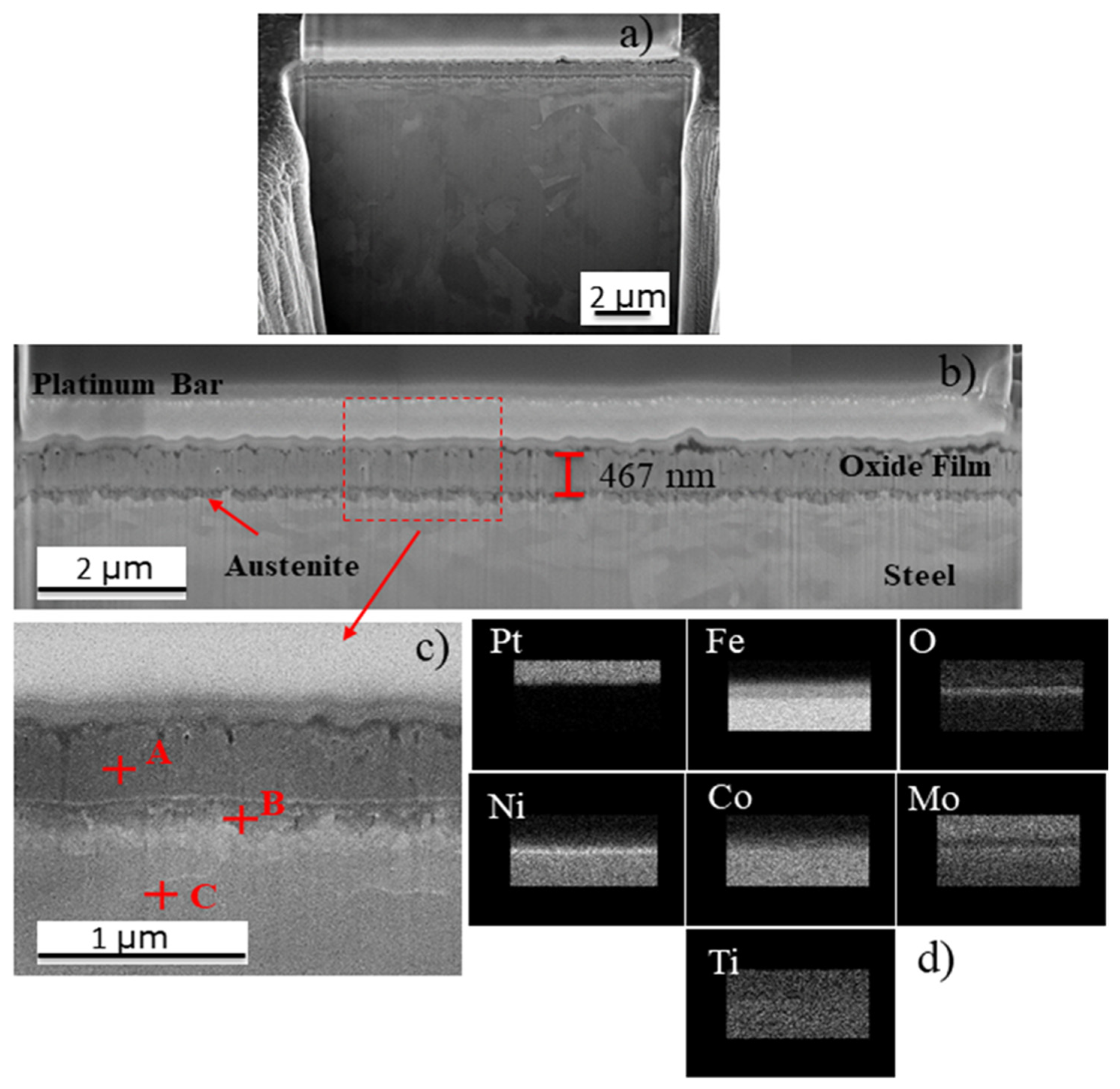
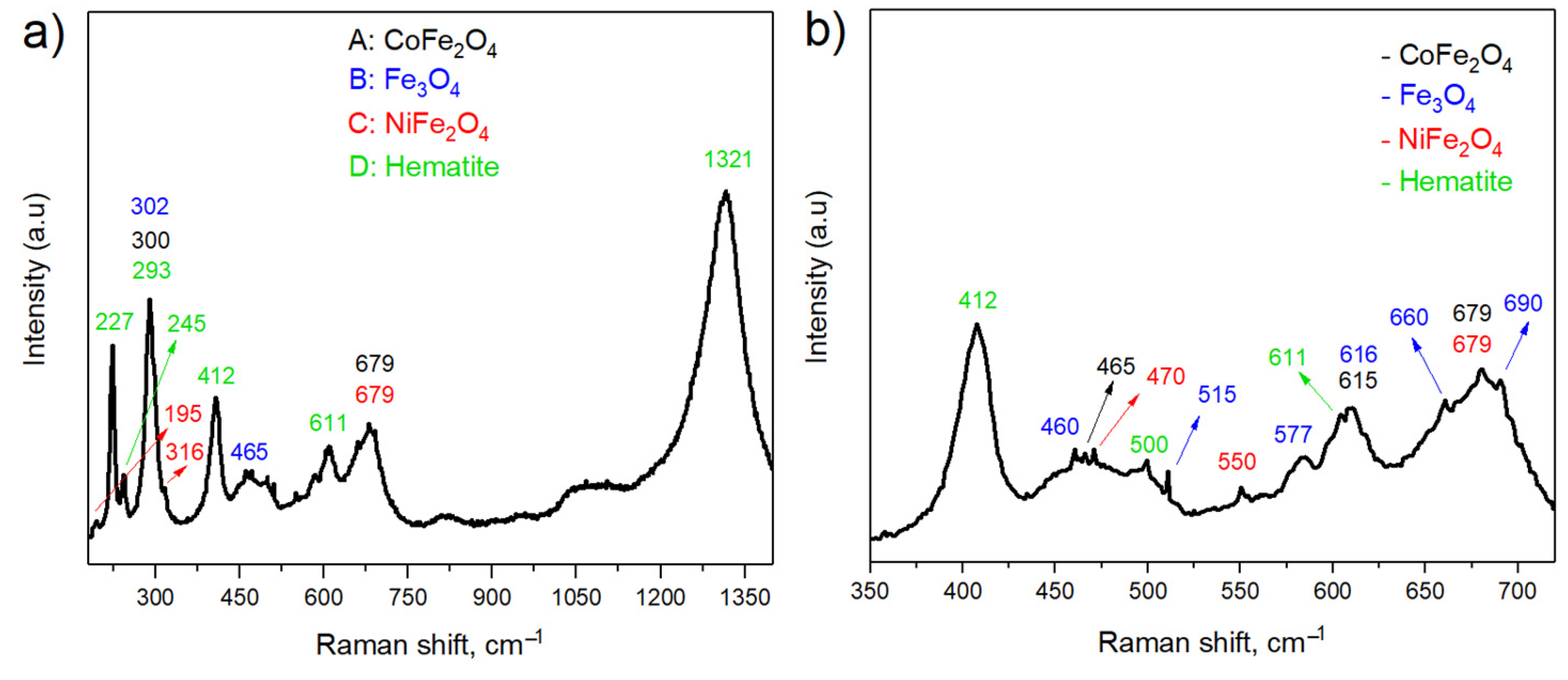
3. Results and Discussion

The diffractogram spectrum of the maraging 300 alloy after solution annealing heat treatment at 840 °C for 1 h is depicted in Figure 1. All the peaks correspond to the martensitic (α’-) phase (with a body-centered cubic structure, bcc), characteristic of this material. The spectrum is in agreement with those reported in [20].
A scanning electron microscope (SEM) micrograph of the surface after polishing is shown in Figure 2a, where some grinding marks are clearly visible. On the other hand, the main energy-dispersive X-ray spectroscopy (EDS) chemical element maps are showed in Figure 2b. From the chemical measurement it is evident that the main elements (Fe, Ni, Co, Mo, and Ti) are homogenously distributed along the specimen after solution annealing. In this sense, no heterogeneities in terms of chemical composition are visible in the modified surface.
Figure 3a,b show the laser scanning confocal microscopy (LSCM) micrographs, where clearly exhibits different kinds of defects like ridges, valleys, and peeling heterogeneously distributed in the oxide layer. In order to get more details about the quality of the surface oxidation process, the morphology of the surface of these images were done by using the atomic force microscopy (AFM) technique. Figure 3c,d show the topographic AFM images (3D-view) at different magnifications; 40 μm × 40 μm and 6.6 μm × 6.6 μm, respectively. From these images it is possible to extract the main roughness parameters (i.e., maximum roughness, maximum and minimum roughness peak; Rz, Rp and Ry, respectively), as summarized in Table 2.
The X-ray diffraction (XRD) spectra for each specimen investigated here are presented in Figure 4. Several peaks, {012}, {104}, {110}, {113}, {024}, {116}, {214} and {300}, confirm the formation of hematite (Fe2O3), in fair agreement with the values reported in Reference [21]. Additionally, the (Fe, Co, Ni) spinel oxide appears at {111}, {220}, {311}, {400}, {422}, {511} and {400} in agreement with [22]. On the other hand, the peak {111} at 2θ around 51°, indicates the presence of the austenitic (γ) phase [23,24]. This γ-phase is rich in Fe, Co, and mainly in Ni, as found in References [8,9,24,25,26]. This layer will act as a bonding layer and will enhance the adhesion between the oxidized layer and the metallic substrate. By using the methodology presented in References [17,18], it was possible to quantify the spinel and hematite contents present in the oxidized layer, being their values of 61 and 39%, respectively. It is important to highlight that the spinel peaks present in the XRD spectrum also fit with the Fe3O4, NiFe2O4, and CoFe2O4, which have similar crystallographic parameters. However, this technique does not lead to isolate each contribution as reported Klein et al. [25].
Scanning electron microscope (SEM) micrographs of the oxide layer are given in Figure 5. Several heterogeneities and/or defects, heterogeneously distributed along the oxidized layer, are visible (indicated with red circles). In this sense, the oxidized layer presents several nodules (Figure 5a), holes (Figure 5b), and porosity, as depicted in Figure 5c,d. Furthermore, several morphological irregularities with different depth, that suggest a non-homogeneous oxide layer, are depicted in Figure 5e. Finally, an oxidized cross section of the layer is shown in Figure 5f, showing a non-homogeneous layer thickness of around 2.9 ± 0.4 μm. Energy-dispersive X-ray spectroscopy (EDS) measurements made in several points A (oxide surface) and B (elongated white formations) are presented in Figure 5d and summarized in Table 3. The values obtained reveal two types of chemical compositions, one rich in Fe and the other with appreciable amounts of Fe, Co, and Ni, suggesting that the first corresponds to hematite while the second one to spinel. It is essential to indicate that oxygen was only taken into account for comparative purposes.
The energy-dispersive X-ray spectroscopy (EDS) maps conducted in different zones of the oxidized surface are depicted in Figure 6. The oxide layer has a homogeneous element distribution, as presented in Figure 6b. On the other hand, when the oxide layer presents discontinuities (i.e., holes, etc.), the EDS maps highlight that this layer is enriched on Mo and Ti, while less content of Ni and Co are present in those discontinuities. Figure 6e shows the line scan (red dash line) analysis through one of the discontinuities (being this discontinuity a detachment of the oxide layer) present in the oxide layer. This element profile is in fair agreement with the chemical maps presented in Figure 6d conducted on the red square in Figure 6c. Furthermore, this analysis confirms that within these discontinuities there is an increase in the amount of Mo and Ti, which can be associated mainly with two different phenomena: (1) the presence of titanium nitrides (TiN) formed during steel manufacture, with appreciable amounts of N and Ti [27,28], and (2) an area rich in Fe, Ni, Mo, and Ti, which leads to create different intermetallic compounds (Ni3Ti, Ni3Mo, Fe3Ti, and Fe3Mo) that precipitate during the aging treatment, in agreement with References [1,4,5,29,30]. It is worthy to mention that these intermetallic phases are very stable and do not form oxides, breaking the homogeneity of the oxidized layer.
In order to observe the microstructure, as well as be able to determine the oxide layer thickness, a cross section micrograph was done by means of focused ion beam (FIB) (Figure 7a). From this micrograph, it is possible to discern a homogeneous oxide layer with a thickness of around 467 ± 33 nm and a metal fine grain microstructure just below (112 ± 24 nm). On the other hand, a closer inspection (Figure 7b), dark shades are visible that suggest the presence of different phases. This assumption was confirmed by performing energy-dispersive X-ray spectroscopy (EDS) chemical analysis in three different regions (A: oxide film, B: oxide layer/metal base interface and C: metal base), as shown in Figure 7c and summarized in Table 4. It is essential to indicate that oxygen was only taken into account for comparative purposes. These results highlight that the oxidized layer presents a uniform distribution from a chemical point of view. As it is evident in Table 4, Ni shows a higher concentration in the oxide layer near the metal base interface. This fact may be related to the generation of an γ-bonding layer at the oxide layer/metal base interface, in fair agreement with References [8,9,24,25,26] and also found by X-ray diffraction XRD (see Figure 4). A decreasing compositional gradient towards the surface was also observed on Figure 7d, suggesting the formation of oxide compounds. The obtained results are in concordance with those reported in References [8,24,26].
In order to identify the spinels, Raman spectroscopy technique was used. Figure 8a shows the Raman spectrum obtained from the oxide layer, in which it is possible to see some peaks of hematite according to [31,32] and some of spinel’s. Furthermore, by doing a magnification at a Raman shift ranged between 350 and 715 cm−1, the spinel peaks are most clearly visible (see Figure 8b). Additionally, in the same representation it is possible to observe the hematite, spinel’s (Fe3O4 [33,34], NiFe2O4 [34,35] and CoFe2O4 [36,37]) peaks. On the other hand, no Ti or Mo oxide peaks were found.
The highly oxidizing water vapor effect can explain the oxidation process of maraging 300 alloy at temperatures above 300 °C [38]. In this sense, the oxide formation has the following steps: (1) decomposition of H2O in mixed gases, (2) adsorption of dissociated oxygen on the steel surface, and (3) reaction between oxygen ions and metal ions [25,38]. Thus, it can be said that, in the initial stage of oxidation, metal atoms become ions that quickly diffuse together with electrons and react with oxygen to form the first layer [8,25,38]. Surman [39] and Subbaraman et al. [40] identified values of the oxide formation energies for Fe, Ni, Co, Mo, and Ti, in atmospheres containing water vapor. They mentioned that all these elements oxidize at the same time in the initial stage and in the case of titanium, due to its greater reactivity, it could form TiO2. This compound was not found in this research, but the energy-dispersive X-ray spectroscopy (EDS) maps showed a higher concentration of this element in the oxide layer/metal base interphase, indicating its existence. Authors mentioned above indicate that MoO3, CoO, FeO, and NiO, form initially; but due to the limited diffusion rate of Ti, Mo, Co, and Ni ions, they are covered by the Fe oxide. It is also said that this oxide acts as a barrier to the migration of Mo and Ti ions.
The growing oxide layer process mainly depends on the partial pressure of oxygen attributed to transport of ionic species, and electrons through the formed layer [8]. It has been explained in the literature that the oxide growth in maraging steels depends mainly on the movement of metal ions through the FeO oxide layer; that is, it grows through the oxide layer/gas interface [8,9]. Furthermore, hematite phase is formed due to the atmospheres used during aging process. Zhang et al. [41] and Hong et al. [42] described that during oxidation between 375 and 526 °C in atmospheres containing water vapor, the outermost layers are exposed to a higher concentration of oxygen, and part of the magnetite oxidizes to hematite (Fe3O4 → α-Fe2O3) [40,41,42,43].
Previous works [7,36,38] mentioned that during aging, thermodynamic and kinetic conditions are created that favor the preferential formation of Fe3O4 spinel. Small amounts of Co and Ni can be found in the oxide as substitutional combinations in the magnetite microstructure, but not forming different compounds [10,40,43]. However, in this research Ni and Co ferrites (NiFe2O4 and CoFe2O4, respectively) have been found and fully identified within the oxide as it has been through the chemical and microstructural analysis presented above. This is due to the differences in the chemical composition of the studied steels because the employed maraging 300 alloy has a greater amount of Mo, Ti, and Co, and these elements, during the thermal treatment in atmospheres containing water vapor, induce an increase in the diffusion process of Co2+ and Ni2+ ions from the metal base towards the outer part of the material, being able to create the aforementioned oxide layer due to a replacement of Fe2+ ions located in the octahedral sites of the spinel transforming part of the magnetite into NiFe2O4 and CoFe2O4 [12,22,44,45,46,47].
Finally, in the scratch tests (used to determine the adhesive damage denoted as Pc2) there is a large shear stress on the surface caused by friction between the indenter and the material [24,48,49]. Figure 9a,b shows the top-view Field emission scanning electron microscopy (FE-SEM) micrographs of the scratch track performed under linear increasing applied load up to 100 mN for the investigated specimen. The behavior is clearly discerned by comparing the micro-fracture events and damage features in regions close to track edges. Some interesting features and damage events as decohesion are clearly visible on the sides of all grooves one can observe pileups as well as loose material in the form of flakes produced by the flow of plastically deformed material and which is responsible of the serrated shape along the scratch track. The Pc2 directly determined from the FE-SEM micrograph is 99 mN. This Pc2 value shows that the film presents excellent adherence comparing with the result published by Florez et al. [24], and the results shows the capability for being used for tribological applications under sliding contact tests [24,48].

4. Conclusions

This study of the oxidation behavior of maraging 300 alloy in water vapor and nitrogen at 500 °C showed that, although there are considerable amounts of elements known for their corrosion resistance, the kinetic and thermodynamic phenomena did not allow the formation of oxides that could protect the steel from the chemical degradation imposed by the exposure conditions. In this sense, such phenomena are the precipitation of intermetallic compounds rich in these elements during the aging heat treatment and the more incredible iron diffusion speed through the oxide layer.
The heat treatment highlights the formation of a homogeneous oxide layer of a dual phase material (hematite and mainly spinel) of around 467 ± 33 nm, covering the entire surface with some imperfections, like holes. From the innermost towards the oxide surface exists a variable composition that confirms the formation of different compounds due to the oxidation and diffusion of Fe, Ti, Mo, and Co. A Ni rich austenitic bonding layer is formed on the oxide layer/metal interface, contrary to the findings reported by other authors who found TiO2, MoO3, NiO, and CoO oxides.
Due to the chemical composition, kinetic and thermodynamic conditions during the heat treatment, there was diffusion of Co and Ni ions through magnetite initially formed and they replaced the Fe atoms that are located in the octahedral holes of the spinel’s structure, being this process the main responsible of the transformation of magnetite into CoFe2O4 and NiFe2O4, as highlighted by the results obtained by Raman spectroscopy.
The scratch tests show an excellent adherence between the formed oxide layer and the metallic substrate and demonstrate its capability for being used under aggressive conditions mainly for tribological applications under sliding contact tests. The chemical and adhesion characteristics of the oxide produced make this film have potential for applications in coatings that can improve the electrochemical behavior, in addition to applications in equipment manufactured with maraging steels used for processing minerals where it is subjected to wear.

Author Contributions

Conceptualization, M.A.C.F., G.F.R. and M.J.G.d.S.; Data Curation, M.A.C.F.; Formal Analysis, M.A.C.F., J.J.R.R., A.M.M.G. and H.F.G.d.A.; Funding Acquisition, M.A.C.F., G.F.R., J.J.R.R., A.M.M.G., H.F.G.d.A. and M.J.G.d.S.; Investigation, M.A.C.F., J.J.R.R., M.B.-N. and A.M.M.G.; Methodology, M.A.C.F., G.F.R. and M.J.G.d.S.; Project Administration, M.A.C.F., G.F.R. and M.J.G.d.S.; Resources, J.J.R.R., A.M.M.G., M.B.-N., H.F.G.d.A., G.F.R. and M.J.G.d.S.; Supervision, M.A.C.F., G.F.R. and M.J.G.d.S.; Validation, J.J.R.R., J.L.C., A.M.M.G., H.F.G.d.A., G.F.R. and M.J.G.d.S.; Visualization, M.A.C.F., J.J.R.R., J.L.C., G.F.R. and M.J.G.d.S.; writing—original draft preparation, M.A.C.F., J.J.R.R., J.L.C., A.M.M.G. and H.F.G.d.A.; writing—review and editing, M.A.C.F., J.J.R.R., J.L.C., A.M.M.G., H.F.G.d.A., M.B.-N., G.F.R. and M.J.G.d.S. All authors have read and agreed to the published version of the manuscript.

Funding

This research was funded by the Coordenação de Aperfeiçoamento de Pessoal de Nível Superior (CAPES) grant number PRINT-88887.371681/2019-00.

Institutional Review Board Statement

Not applicable.

Informed Consent Statement

Not applicable.

Data Availability Statement

Not applicable.

Acknowledgments

The authors gratefully acknowledge to the CAPES/PRINT-UFC and FUNCAP agencies for financial assistance. The authors would like to thank the Central Analítica-UFC (funded by Finep-CT-INFRA, CAPES-Pró-Equipamentos, and MCTI-CNPq-SisNano2.0) for microscopy measurements, the Barcelona Research Center in Multiscale Science and Engineering—UPC, CIEFMA-UPC, LACAM-UFC and GPSA-UFC research groups for technical support. J.J.Roa acknowledges the Serra Hunter programme of the “Generalitat de Catalunya”.

Conflicts of Interest

The authors declare no conflict of interest.

References

  1. Magnée, A.; Drapier, J.M.; Coutsouradis, D.; Habrakan, L.; Dumont, J. Cobalt-Containing High-Strength Steels; Centre d’Information du Cobalt: Brussels, Belgium, 1974; p. 128. Available online: http://refhub.elsevier.com/S0360-3199(19)31930-5/sref1 (accessed on 10 March 2020).
  2. Nickel Development Institute. 18 per Cent Nickel Maraging Steels: Engineering Properties; No. 4419; Nickel Development Institute: Toronto, ON, Canada, 1976; Available online: https://nickelinstitute.org/media/1598/18_nickelmaragingsteel_engineeringproperties_4419_pdf (accessed on 15 March 2020).
  3. Schmidt, M.; Rohrbach, K. Heat Treating of Maraging Steel. In ASM International ASM Handbook; ASM International: Materials Park, OH, USA, 1991; Volume 4, pp. 219–228. [Google Scholar] [CrossRef]
  4. Petty, E.R. Martensite; Fundamentals and Technology: Edited by ER Petty. J. Appl. Cryst. 1970, 4, 402–403. [Google Scholar] [CrossRef] [Green Version]
  5. Rack, H.J.; Kalish, D. The strength and fracture toughness of 18 Ni (350) maraging steel. Metall. Mater. Trans. B 1971, 2, 3011–3020. [Google Scholar] [CrossRef]
  6. Cerra Florez, M.A.; Pereira, U.C.; Cardoso, J.L.; Oliveira, F.J.S.; Araújo, W.S.; Ribas, G.F.; De Abreu, H.F.G.; Da Silva, M.J.G. Microstructural characterization of grade 300 and grade 350 maraging steels and electrochemical study in hydrofluoric solution. J. Fluor. Chem. 2021, 243, 109738. [Google Scholar] [CrossRef]
  7. Viswanathan, U.K.; Dey, G.K.; Asundi, M.K. Precipitation hardening in 350 grade maraging steel. Metall. Trans. A 1993, 24, 2429–2442. [Google Scholar] [CrossRef]
  8. Klein, I.E.; Yaniv, A.E.; Sharon, J. The oxidation mechanism of Fe-Ni-Co alloys. Oxid. Met. 1981, 16, 99–106. [Google Scholar] [CrossRef]
  9. Rezek, J.; Klein, I.E.; Yahalom, J. Structure and corrosion resistance of oxides grown on maraging steel in steam at elevated temperatures. Appl. Surf. Sci. 1997, 108, 159–165. [Google Scholar] [CrossRef]
  10. Greyling, C.J.; Kotzé, I.A.; Viljoen, P.E. The kinetics of oxide film growth on Maraging steel as described by space-charge effects. Surf. Interface Anal. 1990, 16, 293–298. [Google Scholar] [CrossRef]
  11. Parkinson, G. Iron oxide surfaces. Surf. Sci. Rep. 2016, 71, 272–365. [Google Scholar] [CrossRef] [Green Version]
  12. Rodrigues, A.P.G.; Gomes, D.K.S.; Araújo, J.H.; Melo, D.M.A.; Oliveira, N.A.S.; Braga, R.M. Nanoferrites of nickel doped with cobalt: Influence of Co2+ on the structural and magnetic properties. J. Magn. Magn. Mater. 2015, 374, 748–754. [Google Scholar] [CrossRef]
  13. Diniz, V.C.S.; Dantas, B.B.; Figueiredo, A.R.; Cornejo, D.R.; Costa, A. Microstructural and magnetic evaluation of Fe3O4 synthesized by the combustion reaction method. Cerâmica 2015, 61, 298–302. [Google Scholar] [CrossRef] [Green Version]
  14. Horcas, I.; Fernández, R. WSXM: A software for scanning probe microscopy and a tool for nanotechnology. Rev. Sci. Instrum. 2007, 78, 013705. [Google Scholar] [CrossRef]
  15. Zhang, Y.; Cui, K.; Gao, Q.; Hussain, S.; Lv, Y. Investigation of morphology and texture properties of WSi2 coatings on W substrate based on contact-mode AFM and EBSD. Surf. Coat. Technol. 2020, 396, 125966. [Google Scholar] [CrossRef]
  16. Nwaogu, U.C.; Tiedje, N.S.; Hansen, H.N. A non-contact 3D method to characterize the surface roughness of castings. J. Mater. Process. Technol. 2013, 213, 59–68. [Google Scholar] [CrossRef]
  17. Gadelmawla, E.S.; Koura, M.M.; Maksoud, T.M.A.; Elewa, I.M.; Soliman, H.H. Roughness parameters. J. Mater. Process. Technol. 2002, 123, 133–145. [Google Scholar] [CrossRef]
  18. Chung, F. Quantitative Interpretation of X-ray Diffraction Patterns of Mixtures. I. Matrix-Flushing Method for Quantitative Multicomponent Analysis. J. Appl. Cryst. 1974, 7, 519. [Google Scholar] [CrossRef]
  19. Zhou, X.; Liu, D.; Bu, H.; Deng, L.; Liu, H.; Yuan, P.; Du, P.; Song, H. XRD-based quantitative analysis of clay minerals using reference intensity ratios, mineral intensity factors, Rietveld, and full pattern summation methods: A critical review. Solid Earth Sci. 2018, 3, 16–29. [Google Scholar] [CrossRef]
  20. Viana, N.F.; Dos Santos, N.C.; De Abreu, H.F.G. The variant selection in the transformation from austenite to martensite in samples of maraging-350 steel. J. Mater. Res. Technol. 2013, 2, 298–302. [Google Scholar] [CrossRef] [Green Version]
  21. JCPDS. X-Ray Diffraction Data Cards of the Joint Committee on Powder Diffraction Standards; International Center for Diffraction Data: Swarthmore, PA, USA, 1975. [Google Scholar]
  22. Dąbrowa, J.; Stygar, M.; Mikuła, A.; Knapik, A.; Mroczka, K.; Tejchman, W.; Martin, M. Synthesis and microstructure of the (Co,Cr,Fe,Mn,Ni)3O4 high entropy oxide characterized by spinel structure. Mater. Lett. 2018, 216, 32–36. [Google Scholar] [CrossRef]
  23. Conde, F.F.; Escobar, J.D.; Oliveira, J.P.; Béreš, M.; Jardini, A.L.; Bose, W.W.; Avila, J.A. Effect of thermal cycling and aging stages on the microstructure and bending strength of a selective laser melted 300-grade maraging steel. Mater. Sci. Eng. A 2019, 758, 192–201. [Google Scholar] [CrossRef]
  24. Florez, M.A.C.; Fargas Ribas, G.; Rovira, J.J.R.; Vilarrasa-García, E.; Rodríguez-Castellón, E.; Sousa, A.B.F.; Cardoso, J.L.; Gomes da Silva, M.J. Characterization Study of an Oxide Film Layer Produced under CO2/Steam Atmospheres on Two Different Maraging Steel Grades. Metals 2021, 11, 746. [Google Scholar] [CrossRef]
  25. Klein, I.E.; Sharon, J.; Yaniv, A.E. A mechanism of oxidation of ferrous aloys by super-heated steam. Scr. Metall. 1981, 15, 141–144. [Google Scholar] [CrossRef]
  26. Klein, I.E.; Yaniv, A.E.; Sharon, J. The Mechanism of Oxidation of Fe-Ni-Co Alloys; The Role of Ti And Mo. Appl. Surf. Sci. 1983, 14, 351–358. [Google Scholar] [CrossRef]
  27. Descotes, V.; Migot, S.; Robaut, F.; Bellot, J.P.; Perrin-Guérin, V.; Witzke, S.; Jardy, A. TEM Characterization of a Titanium Nitride (TiN) Inclusion in a Fe-Ni-Co Maraging Steel. Metall. Mater. Trans. A 2015, 46A, 2793. [Google Scholar] [CrossRef]
  28. Descotes, V.; Quatravaux, T.; Bellot, J.P.; Witzke, S.; Jardy, A. Titanium Nitride (TiN) Germination and Growth during Vacuum Arc Remelting of a Maraging Steel. Metals 2020, 10, 541. [Google Scholar] [CrossRef] [Green Version]
  29. Rodrigues, A.C.; Bernardi, H.H.; Otubo, J. Microstructural Analysis of Co-Free Maraging Steel Aged. J. Aerosp. Technol. Manag. 2014, 6, 389–394. [Google Scholar] [CrossRef] [Green Version]
  30. Moshka, O.; Pinkas, M.; Brosh, E.; Ezersky, V.; Meshi, L. Addressing the issue of precipitates in maraging steels—Unambiguous answer. Mater. Sci. Eng. A 2015, 638, 232–239. [Google Scholar] [CrossRef]
  31. De Faria, D.L.A.; Lopes, F.N. Heated goethite and natural hematite: Can Raman spectroscopy be used to differentiate them? Vib. Spectrosc. 2007, 45, 117–121. [Google Scholar] [CrossRef]
  32. Guo, R.; Dang, L.; Liu, Z.; Lei, Z. Incorporation of electroactive NiCo2S4 and Fe2O3 into graphene aerogel for high-energy asymmetric supercapacitor. Colloids Surf. A 2020, 602, 125110. [Google Scholar] [CrossRef]
  33. Kumar, P.R.; Jung, Y.H.; Bharathi, K.K.; Lim, C.H.; Kim, D.K. High capacity and low cost spinel Fe3O4 for the Na-ion battery negative electrode materials. Electrochim. Acta 2014, 146, 503–510. [Google Scholar] [CrossRef]
  34. Robinson, M.R.; Abdelmoula, M.; Mallet, M.; Coustel, R. Starch functionalized magnetite nanoparticles: New insight into the structural and magnetic properties. J. Solid State Chem. 2019, 277, 587–593. [Google Scholar] [CrossRef]
  35. Gao, X.; Bi, J.; Wang, W.; Liu, H.; Chen, Y.; Hao, X.; Sun, X.; Liu, R. Morphology-controllable synthesis of NiFe2O4 growing on graphene nanosheets as advanced electrode material for high performance supercapacitors. J. Alloys Compd. 2020, 826, 154088. [Google Scholar] [CrossRef]
  36. Wang, W.; Ding, Z.; Zhao, X. Microstructure and magnetic properties of MFe2O4 (M = Co, Ni, and Mn) ferrite nanocrystals prepared using colloid mill and hydrothermal method. J. Appl. Phys. 2015, 117, 17A328. [Google Scholar] [CrossRef] [Green Version]
  37. Routray, K.L.; Saha, S.; Behera, D. Nanosized CoFe2O4-graphene nanoplatelets with massive dielectric enhancement for high frequency device application. Mater. Sci. Eng. B 2020, 257, 114548. [Google Scholar] [CrossRef]
  38. Luo, D.W.; Shen, Z.S. Oxidation behavior of Kovar alloy in controlled atmosphere. Acta Metall. Sin. Engl. Lett. 2008, 21, 409–418. [Google Scholar] [CrossRef]
  39. Surman, P.L. The oxidation of iron at controlled oxygen partial pressures—I. Hydrogen/water vapour. Corros. Sci. 1973, 13, 113–124. [Google Scholar] [CrossRef]
  40. Subbaraman, R.; Deshmukh, S.A.; Sankaranarayanan, S.K. Atomistic insights into early stage oxidation and nanoscale oxide growth on Fe (100), Fe (111) and Fe (110) surfaces. J. Phys. Chem. C 2013, 117, 5195–5207. [Google Scholar] [CrossRef]
  41. Zhang, X.; Yang, S.; Yang, Z.; Xu, X. Kinetics and intermediate phases in epitaxial growth of Fe3O4 films from deposition and thermal reduction. J. Appl. Phys. 2016, 120, 085313. [Google Scholar] [CrossRef] [Green Version]
  42. Hong, H.; Memon, N.K.; Dong, Z.; Kear, B.H.; Stephen, D.T. Flame synthesis of gamma-iron-oxide (γ-Fe2O3) nanocrystal films and carbon nanotubes on stainless-steel substrates. Proc. Combust. Inst. 2019, 37, 1249–1256. [Google Scholar] [CrossRef]
  43. Jeon, B.; Van Overmeere, Q.; Van Duin, A.C.; Ramanathan, S. Nanoscale oxidation and complex oxide growth on single crystal iron surfaces and external electric field effects. Phys. Chem. Chem. Phys. 2013, 15, 1821–1830. [Google Scholar] [CrossRef]
  44. Genuzio, F.; Sala, A.; Schmidt, T.; Menzel, D.; Freund, H.J. Phase transformations in thin iron oxide films: Spectromicroscopic study of velocity and shape of the reaction fronts. Surf. Sci. 2016, 648, 177–187. [Google Scholar] [CrossRef]
  45. Tsukimura, K.; Sasaki, S.; Kimizuka, N. Cation Distributions in Nickel Ferrites. Jpn. J. Appl. Phys. 1997, 36, 3609. [Google Scholar] [CrossRef]
  46. Bliem, R.; Pavelec, J.; Gamba, O.; McDermott, E.; Wang, Z.; Gerhold, S.; Blaha, P. Adsorption and incorporation of transition metals at the magnetite Fe3O4 (001). Phys. Rev. B 2015, 92, 75440. [Google Scholar] [CrossRef] [Green Version]
  47. Pardavi-Horvath, M. Microwave applications of soft ferrites. J. Magn. Magn. Mater. 2000, 215–216, 171–183. [Google Scholar] [CrossRef]
  48. Ghasemi Parizi, M.J.; Shahverdi, H.; Roa, J.J.; Pipelzadeh, E.; Martinez, M.; Cabot, A.; Guardia, P. Improving Mechanical Properties of Glass Fiber Reinforced Polymers through Silica-Based Surface Nanoengineering. ACS Appl. Polym. Mater. 2020, 2, 2667–2675. [Google Scholar] [CrossRef]
  49. ASTM C1624. Standard Test Method for Adhesion Strength and Mechanical Failure Modes of Ceramic Coatings by Quantitative Single Point Scratch Testing; Annual Book of ASTM Standards; ASTM International: West Conshohocken, PA, USA, 2015. [Google Scholar]
Figure 1. X-ray diffraction (XRD) spectrum of the maraging 300 alloy after solution annealing treatment at 840 °C showing α’—peaks.
Metals 11 01021 g001
Figure 2. (a) Scanning electron microscope (SEM) micrograph of the grade 300 maraging steel surface after treatment and (b) energy-dispersive X-ray spectroscopy (EDS) elements map of the main constituents.
Metals 11 01021 g002
Figure 3. (a,b) laser scanning confocal microscopy (LSCM) surface micrographs observation, and topographic atomic force microscopy (AFM) image (3D view) of the (c) initial surface and (d) the oxide layer growth on maraging 300 alloy.
Metals 11 01021 g003
Figure 4. X-ray diffraction (XRD) spectra of the oxide layer formed on maraging 300 alloy. Peaks corresponding to γ-phase, Hematite and (Fe,Co,Ni) spinel are visible in the spectra.
Metals 11 01021 g004
Figure 5. Scanning electron microscope (SEM) micrographs of the oxide produced on maraging 300 alloy, showing different heterogeneities, such as, (a) nodules, (b) holes, (c) porosity and (d,e) depicted on the surface; and (f) cross section of the oxide layer.
Metals 11 01021 g005
Figure 6. (a,c,e) Scanning electron microscope (SEM) micrographs (of the oxide produced on maraging 300 alloy) of the analyzed surface, (b,d) Energy-dispersive X-ray spectroscopy (EDS) chemical maps and (f) chemical elements profiles conducted on the through the red dash line of the (e).
Metals 11 01021 g006
Figure 7. Scanning electron microscope (SEM) micrographs of the oxide layer formed in maraging 300 alloy, (a) focused ion beam (FIB)-cross section micrograph of the oxide layer, (b) thickness of the oxide layer, (c) magnification of the oxide layer showing the three different points where the chemical composition were determined, and (d) energy-dispersive X-ray spectroscopy (EDS) maps analysis for different metallic elements present in the oxide later (Fe, O, Ni, Co, Mo and Ti) in the region described in (c).
Metals 11 01021 g007
Figure 8. Raman spectrum collected from the oxide layer produced on maraging 300 alloy, showing the main compound peaks. (a) General view and (b) a high magnification ranged between 350 and 715 cm−1.
Metals 11 01021 g008
Figure 9. (a) Field emission scanning electron microscopy (FE-SEM) micrograph for the nanoscratch track and (b) magnification of the top-view (FE-SEM) image of nanoscratch tracks where the first adhesive damage appears for the reference sample.
Metals 11 01021 g009
Table 1. Chemical composition (wt %) of maraging 300 alloy.
NiCoMoTiCrVSiAlCuMnCFe
18.289.514.800.730.120.100.080.070.050.03<0.01Bal.
Table 2. Summary of the main roughness parameters for the reference sample and the oxide layer.
Roughness (nm)
ParameterSteel surfaceOxide surface
Roughness Average (Ra)52 ± 517 ± 0.5
Roughness Maximum (Rz)295177
Max Peak ht (Rp)11096
Maximum Depth (Rv)−185−81
Table 3. Energy-dispersive X-ray spectroscopy (EDS) analysis performed at two different points (as shown in Figure 5d).
EDS Quantitative Analysis from A and B Points (wt %)
Element NumberElement SymbolPoint APoint B
26Fe38.8733.46
8O36.3762.30
27Co11.191.91
28Ni12.932.33
42Mo0.54-
22Ti0.10-
Table 4. Energy-dispersive X-ray spectroscopy (EDS) measurements for the three different points shown in Figure 7d.
EDS Quantitative Analysis from Points A, B and C (wt %)
Elem. NumberElem. SymbolPoint APoint BPoint C
26Fe44.0838.1163.69
8O26.072.33-
27Co13.2811.4012.08
28Ni15.8144.1719.64
42Mo0.633.273.99
22Ti0.150.720.60
Publisher’s Note: MDPI stays neutral with regard to jurisdictional claims in published maps and institutional affiliations.

