
The Orowan Stress Measurement of Twinning Dislocations in Magnesium


Abstract
:1. Introduction
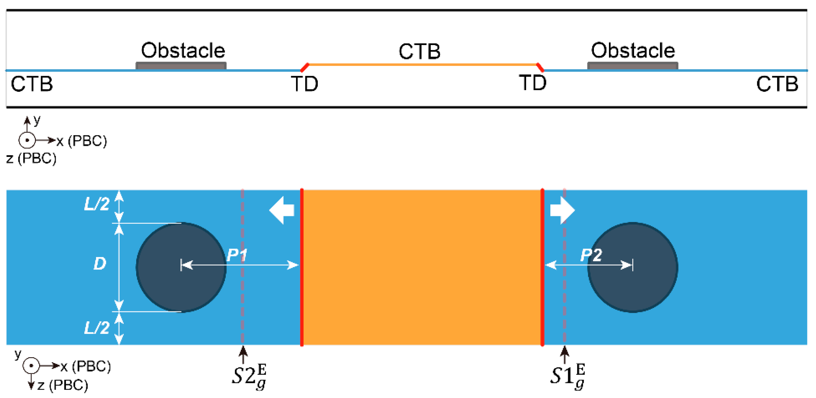
2. Materials and Methods
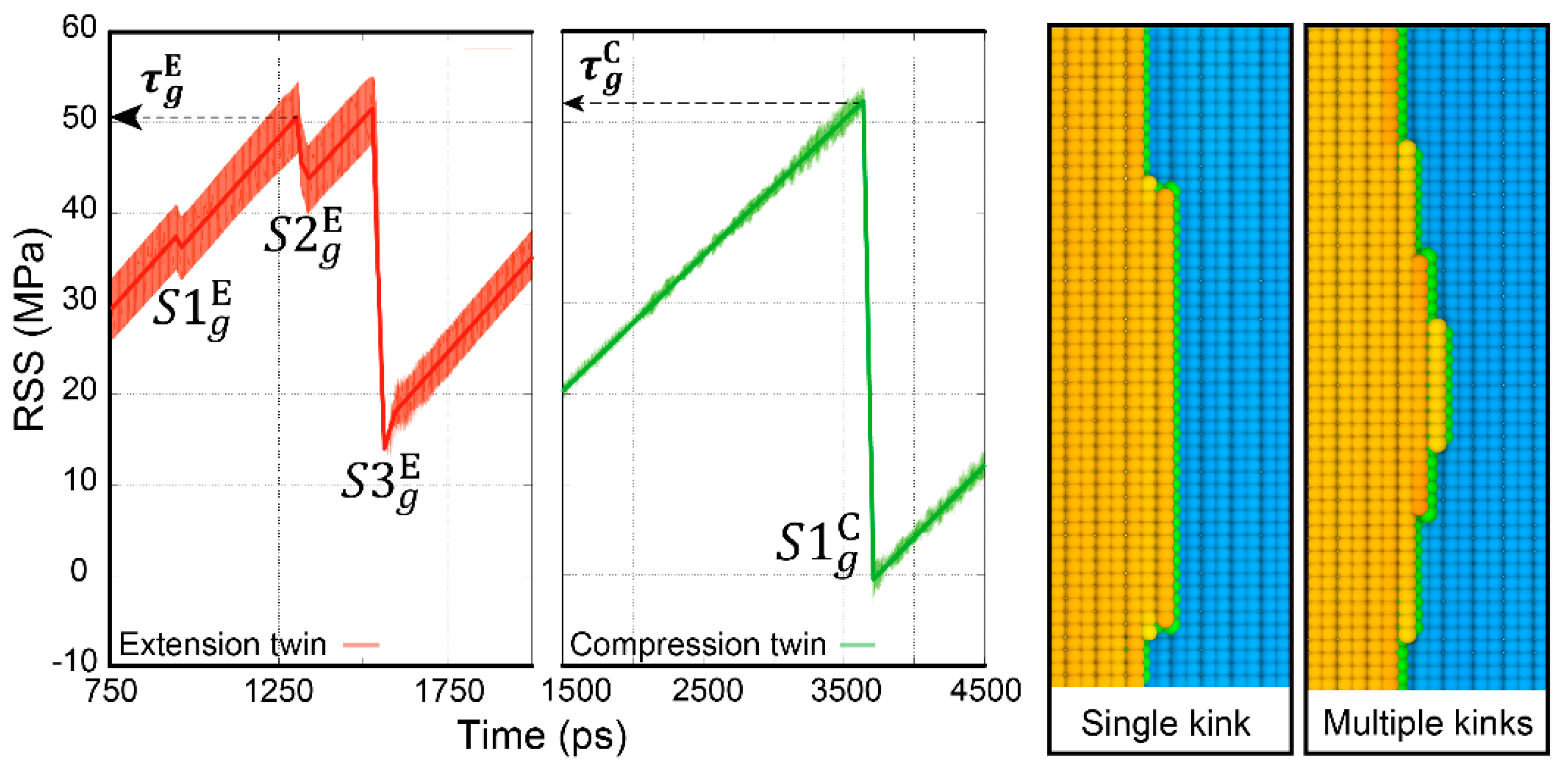
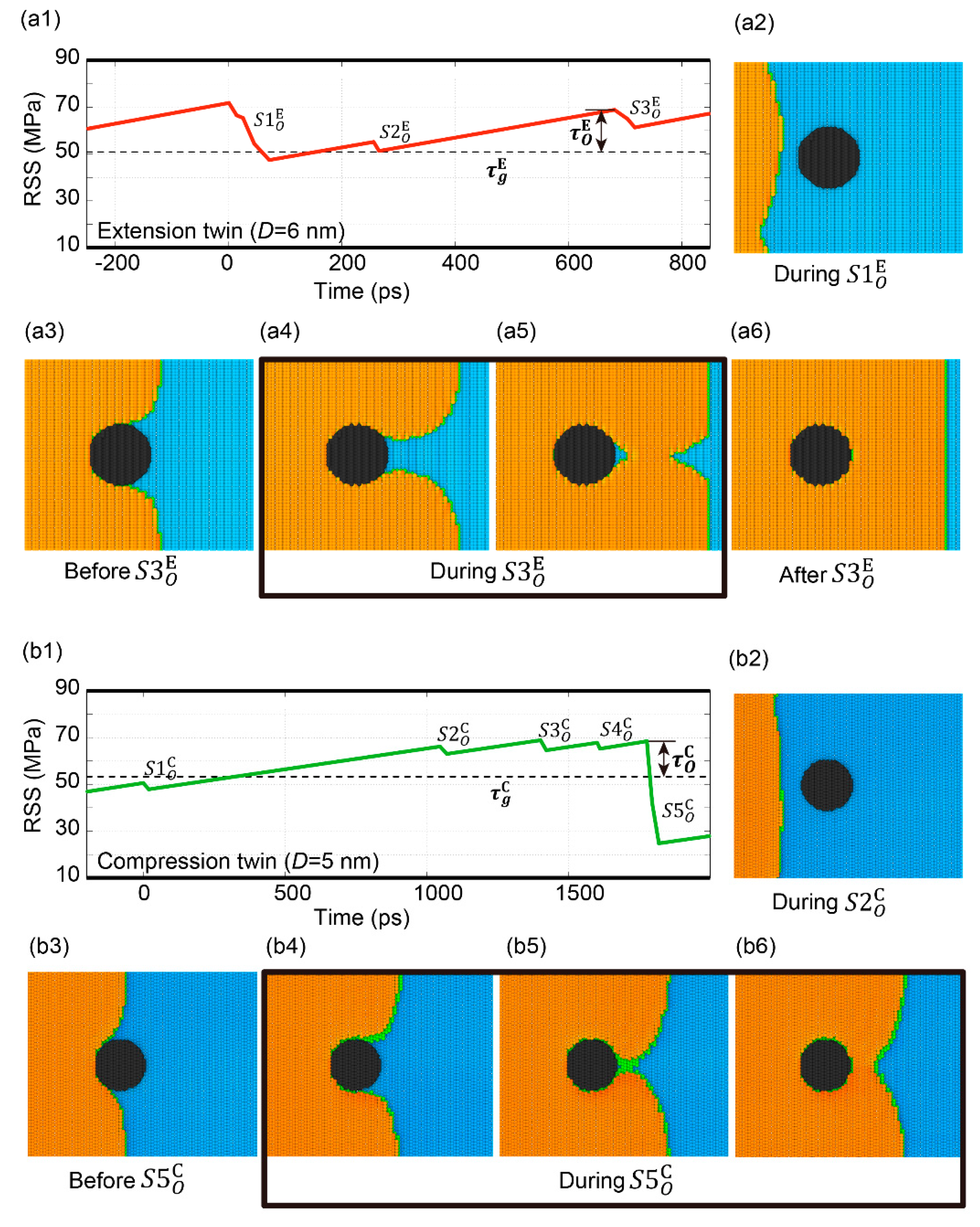
3. Results
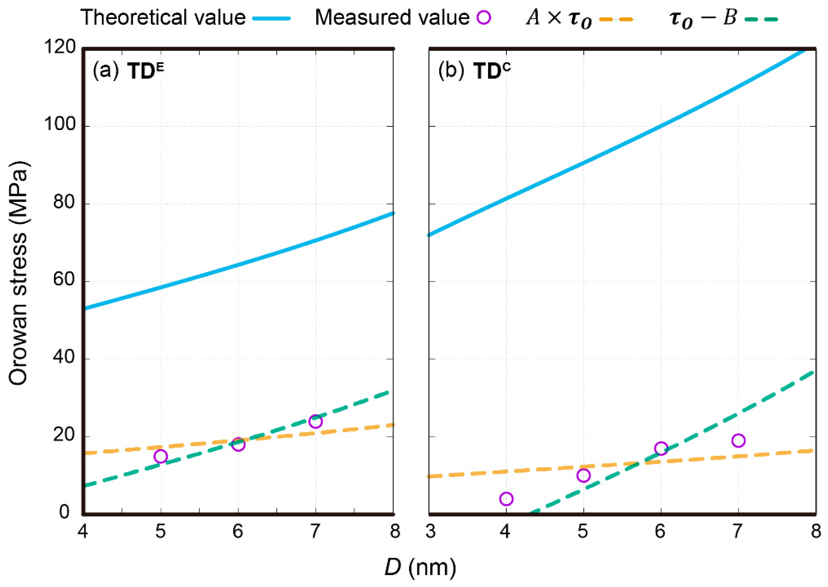
4. Discussion
5. Conclusions
Author Contributions
Funding
Institutional Review Board Statement
Informed Consent Statement
Conflicts of Interest
References
- Bacon, D.; Kocks, U.; Scattergood, R. The effect of dislocation self-interaction on the Orowan stress. Philos. Mag. 1973, 28, 1241–1263. [Google Scholar] [CrossRef]
- Ma, X.; Jiao, Q.; Kecskes, L.J.; El-Awady, J.A.; Weihs, T.P. Effect of basal precipitates on extension twinning and pyramidal slip: A micro-mechanical and electron microscopy study of a Mg–Al binary alloy. Acta Mater. 2020, 189, 35–46. [Google Scholar] [CrossRef]
- Wang, C.; Cepeda-Jiménez, C.M.; Pérez-Prado, M.T. Dislocation-particle interactions in magnesium alloys. Acta Mater. 2020, 194, 190–206. [Google Scholar] [CrossRef]
- Alizadeh, R.; LLorca, J. Interactions between basal dislocations and β1′ precipitates in Mg–4Zn alloy: Mechanisms and strengthening. Acta Mater. 2020, 186, 475–486. [Google Scholar] [CrossRef]
- Liao, M.; Li, B.; Horstemeyer, M. Interaction Between Basal Slip and a Mg17Al12 Precipitate in Magnesium. Metall. Mater. Trans. A 2014, 45, 3661–3669. [Google Scholar] [CrossRef]
- Vaid, A.; Guénolé, J.; Prakash, A.; Korte-Kerzel, S.; Bitzek, E. Atomistic simulations of basal dislocations in Mg interacting with Mg17Al12 precipitates. Materialia 2019, 7, 100355. [Google Scholar] [CrossRef] [Green Version]
- Esteban-Manzanares, G.; Alizadeh, R.; Papadimitriou, I.; Dickel, D.; Barrett, C.; LLorca, J. Atomistic simulations of the interaction of basal dislocations with MgZn2 precipitates in Mg alloys. Mater. Sci. Eng. A 2020, 788, 139555. [Google Scholar] [CrossRef]
- Hirth, J.P.; Wang, J.; Tomé, C.N. Disconnections and other defects associated with twin interfaces. Prog. Mater. Sci. 2016, 83, 417–471. [Google Scholar] [CrossRef] [Green Version]
- He, Y.; Li, B.; Wang, C.; Mao, S.X. Direct observation of dual-step twinning nucleation in hexagonal close-packed crystals. Nat. Commun. 2020, 11, 1–8. [Google Scholar] [CrossRef]
- Liu, B.-Y.; Yang, N.; Wang, J.; Barnett, M.; Xin, Y.-C.; Wu, D.; Xin, R.-L.; Li, B.; Narayan, R.L.; Nie, J.-F.; et al. Insight from in situ microscopy into which precipitate morphology can enable high strength in magnesium alloys. J. Mater. Sci. Technol. 2018, 34, 1061–1066. [Google Scholar] [CrossRef]
- Zhang, X.Y.; Li, B.; Wu, X.L.; Zhu, Y.T.; Ma, Q.; Liu, Q.; Wang, P.T.; Horstemeyer, M.F. Twin boundaries showing very large deviations from the twinning plane. Scr. Mater. 2012, 67, 862–865. [Google Scholar] [CrossRef] [Green Version]
- Tang, X.-Z.; Guo, Y.-F. The engulfment of precipitate by extension twinning in Mg–Al alloy. Scr. Mater. 2020, 188, 195–199. [Google Scholar] [CrossRef]
- Spearot, D.E.; Capolungo, L.; Tomé, C.N. Shear-driven motion of Mg twin boundaries via disconnection terrace nucleation, growth, and coalescence. Phys. Rev. Mater. 2019, 3, 53606. [Google Scholar] [CrossRef]
- Sato, Y.; Swinburne, T.; Ogata, S.; Rodney, D. Anharmonic effect on the thermally activated migration of twin interfaces in magnesium. Mater. Res. Lett. 2021, 9, 231–238. [Google Scholar] [CrossRef]
- Tang, X.-Z.; Zu, Q.; Guo, Y.-F. The diffusive character of extension twin boundary migration in magnesium. Materialia 2018, 2, 208–213. [Google Scholar] [CrossRef]
- Luque, A.; Ghazisaeidi, M.; Curtin, W.A. A new mechanism for twin growth in Mg alloys. Acta Mater. 2014, 81, 442–456. [Google Scholar] [CrossRef]
- Robson, J.D.; Barnett, M.R. The effect of precipitates on twinning in magnesium alloys. Adv. Eng. Mater. 2019, 21, 1800460. [Google Scholar] [CrossRef]
- Robson, J.D.; Stanford, N.; Barnett, M.R. Effect of precipitate shape on slip and twinning in magnesium alloys. Acta Mater. 2011, 59, 1945–1956. [Google Scholar] [CrossRef]
- Fan, H.; Zhu, Y.; El-Awady, J.A.; Raabe, D. Precipitation hardening effects on extension twinning in magnesium alloys. Int. J. Plast. 2018, 106, 186–202. [Google Scholar] [CrossRef]
- Hidalgo-Manrique, P.; Robson, J.D. Interaction Between Precipitate Basal Plates and Tensile Twins in Magnesium Alloys. Metall. Mat. Trans. A 2019, 50, 3855–3867. [Google Scholar] [CrossRef] [Green Version]
- Stanford, N.; Geng, J.; Chun, Y.B.; Davies, C.H.J.; Nie, J.F.; Barnett, M.R. Effect of plate-shaped particle distributions on the deformation behaviour of magnesium alloy AZ91 in tension and compression. Acta Mater. 2012, 60, 218–228. [Google Scholar] [CrossRef]
- Barnett, M.R. Twinning Super Dislocations to Help Understand Strength. In Proceedings of the International Conference on Martensitic Transformations, Chicago, IL, USA, 9–15 July 2017; pp. 143–145. [Google Scholar]
- Barnett, M.R.; Wang, H.; Guo, T. An Orowan precipitate strengthening equation for mechanical twinning in Mg. Int. J. Plast. 2019, 112, 108–122. [Google Scholar] [CrossRef]
- Wang, J.; Hoagland, R.G.; Hirth, J.P.; Capolungo, L.; Beyerlein, I.J.; Tomé, C.N. Nucleation of a twin in hexagonal close-packed crystals. Scr. Mater. 2009, 61, 903–906. [Google Scholar] [CrossRef]
- Wang, J.; Beyerlein, I.J.; Hirth, J.P.; Tome, C.N. Twinning dislocations on {011} and {013} planes in hexagonal close-packed crystals. Acta Mater. 2011, 59, 3990–4001. [Google Scholar] [CrossRef]
- Zu, Q.; Tang, X.-Z.; Fu, H.; Peng, Q.-M.; Guo, Y.-F. The irrational shear of twinning in Mg. Materialia 2019, 5, 100239. [Google Scholar] [CrossRef]
- Hu, Y.; Curtin, W.A. Modeling peak-aged precipitate strengthening in Al–Mg–Si alloys. J. Mech. Phys. Solids 2021, 151, 104378. [Google Scholar] [CrossRef]
Publisher’s Note: MDPI stays neutral with regard to jurisdictional claims in published maps and institutional affiliations. |
© 2021 by the authors. Licensee MDPI, Basel, Switzerland. This article is an open access article distributed under the terms and conditions of the Creative Commons Attribution (CC BY) license (https://creativecommons.org/licenses/by/4.0/).
Share and Cite
Tang, X.-Z.; Guo, Y.-F. The Orowan Stress Measurement of Twinning Dislocations in Magnesium. Metals 2021, 11, 1020. https://doi.org/10.3390/met11071020
Tang X-Z, Guo Y-F. The Orowan Stress Measurement of Twinning Dislocations in Magnesium. Metals. 2021; 11(7):1020. https://doi.org/10.3390/met11071020
Chicago/Turabian StyleTang, Xiao-Zhi, and Ya-Fang Guo. 2021. "The Orowan Stress Measurement of Twinning Dislocations in Magnesium" Metals 11, no. 7: 1020. https://doi.org/10.3390/met11071020
APA StyleTang, X.-Z., & Guo, Y.-F. (2021). The Orowan Stress Measurement of Twinning Dislocations in Magnesium. Metals, 11(7), 1020. https://doi.org/10.3390/met11071020