Article

Fatigue Assessment of Selective Laser Melted Ti-6Al-4V: Influence of Speed Manufacturing and Porosity

by
Unai Segurajauregi
1,
Adrián Álvarez-Vázquez
2,
Miguel Muñiz-Calvente
2,*,
Íker Urresti
1 and
Haydee Naveiras
1
1
Ikerlan Technology Research Centre, Basque Research and Technology Alliance (BRTA), Paseo J.M. Arizmendiarrieta 2, 20500 Arrasate-Mondragon, Spain
2
Department of Construction and Manufacturing Engineering, University of Oviedo, 33203 Gijón, Spain
*
Author to whom correspondence should be addressed.
Metals 2021, 11(7), 1022; https://doi.org/10.3390/met11071022
Submission received: 3 May 2021 / Revised: 9 June 2021 / Accepted: 22 June 2021 / Published: 25 June 2021
(This article belongs to the Special Issue Additive Manufacturing Research and Applications)

Abstract

:
Additive Manufacturing represents a promising technology as an alternative to the conventional manufacturing process, with rapid and economic product development, as well as a significant weight reduction and a freeform design. Although the mechanical properties of additively manufactured metals, such as the Ti-6Al-4V alloy, are well-established, a complete understanding of the fatigue performance is still a pending aspiration due to its inherent stochastic complexity and the influence of several manufacturing factors. This paper presents a study of the influence of speed manufacturing and porosity in the fatigue behaviour of a Ti-6Al-4V alloy. To this aim, a numerical simulation of the expected porosity at different laser velocities is performed, together with a simulation of the residual stresses. These numerical results are compared with experimental measurements of residual stresses and a qualitative analysis of the porosities. Then, fatigue strength is experimentally obtained for two different laser speeds and fitted by a probabilistic model. As a result, the probabilistic S–N fields for different laser velocities are found to be similar, with scatter bands nearly coincident, drawing the conclusion that this effect is negligible in comparison with other concurrent ones, such as roughness or surface defects from manufacturing conditions, promoting crack initiation and premature fatigue failure.

1. Introduction and Motivation

Additive Manufacturing (AM), formerly known as Rapid Prototyping (RP) (see ASTM F2792-12a [1]), has undoubtedly been increasing over the last two decades as a technology that is disrupting current manufacturing processes, and attracts interest from both industrial and academic perspectives [2,3,4,5]. Known also as 3-D printing, AM consists of a progressive consolidation of raw materials, such as powder or wire, in a layer-by-layer fashion, in an opposite approach to traditional manufacturing processes, which are typically based on machining block parts, that is, the subtraction or removal of material [6]. Moreover, this novel technology has several important advantages compared with traditional methods: an agile development product from Computer Aided Design (CAD) to fabrication; a significant reduction of weight in the final design (with potential reductions of up to nearly 50% [6,7]); and a geometric freedom that allows the production of parts otherwise not possible with conventional methods. Additionally, AM may lead to the reduction of carbon emissions compared with traditional manufacturing processes, due to the use of lighter weight parts [6,8].
Polymeric materials were originally preferred for producing additively manufactured parts [5], but nowadays both non-metallic (composites, ceramics) and metallic materials are usually employed. The titanium (Ti) alloys, in particular, are of great interest because of their increasing use in the aerospace industry due to their weight saving, operating temperature, corrosion resistance and compatibility with biological and composite materials. Unfortunately, their higher cost compared with other alternatives hitherto represents the most important limitation [6,9,10,11,12].
Three different technologies were developed to produce metal additively manufactured parts: Laser Beam Melting (LBM), Laser Metal Deposition (LMD) and Selective Laser Melting (SLM), the latter being the most commonly used [13,14]. In this process, the energy of the laser source is applied to melt powder, as a raw material, within a powder-bed layer. Then, the 3D geometrical design is built up by recoating a new powder-layer and subsequent melting [5]. Nowadays, these manufacturing technologies for developing structural alloys are particularly useful, since the intrinsic heat can be directly used to trigger the chemical reactions, such as those implied in precipitation hardening alloys [15,16].
There are different works in the literature that have focused on researching the influence of different additive manufacturing parameters on the fatigue performance of Ti-6Al-4V, such as the microstructure, the build direction, the residual stresses and the porosity. In the first case, Nalla et al. [17] have investigated the influence of the microstructure on both bimodal and coarser lamellar types, concluding that the latter improved the fatigue behaviour in the HCF zone, whereas Thijs et al. [18] studied the influence of the scanning parameters and scanning strategy on the microstructure during the SLM process. In the second case, Edwards et al. [6,19] presented a study on the effect of the build direction, revealing that the cracks oriented perpendicular to the build layers provide enhanced fatigue crack growth behaviour. Regarding the residual stresses, several researchers [20,21] have found that a high temperature pre-heating during the additive manufacturing process may reduce thermal gradients. Lastly, [22] evidenced that the failure initiation in SLM or EBM manufactured titanium alloys is governed by porosity and lack of fusion. Nevertheless, previous works have not investigated the influence of speed manufacturing, which would be conducted with different porosities and could imply different fatigue behaviours.
The aim of this paper is to study the influence of different laser velocities on the porosity of additively manufactured specimens of the Ti-6Al-4V alloy and to evaluate the fatigue performance associated with those porosities. Firstly, numerical simulations were developed to study the expected porosity considering different laser velocities, together with residual stresses inherent to the manufacturing process. Secondly, these numerical results were compared with experimental measurements of residual stresses and a qualitative analysis of the porosities. Thirdly, a tensile test was conducted on specimens produced at two different laser velocities in order to evaluate its influence on the mechanical properties. After that, a fatigue experimental campaign was carried out on specimens at two different laser speeds and the results were evaluated according to a probabilistic S–N model developed by [23], contrary to the fatigue assessment methodologies performed in the literature, based on deterministic S–N models [24,25,26], through the inherent and non-negligible scatter titanium fatigue tests [6,27,28,29,30,31].
The paper is structured as follows: in Section 2, the material and methods employed in this study are detailed, including the material and geometry selected (Section 2.1), the manufacturing conditions (Section 2.2) and the experimental procedures followed in the testing (Section 2.3). Section 3 details the numerical study of the porosity and the residual stresses together with the experimental results obtained. Section 4 is focused on both the tensile (Section 4.1) and fatigue characterization of two different laser velocities (Section 4.2). Section 5 presents an interpretation of the experimental results and, finally, Section 6 summarises the main conclusions drawn from this work.

2. Materials and Methods

This section describes the material and geometry of the specimens to be used in the experimental campaign in this work. Then, the manufacturing conditions are also detailed, distinguishing different batches of samples fabricated for porosity, tensile and fatigue characterization. Finally, the experimental testing procedures are exposed.

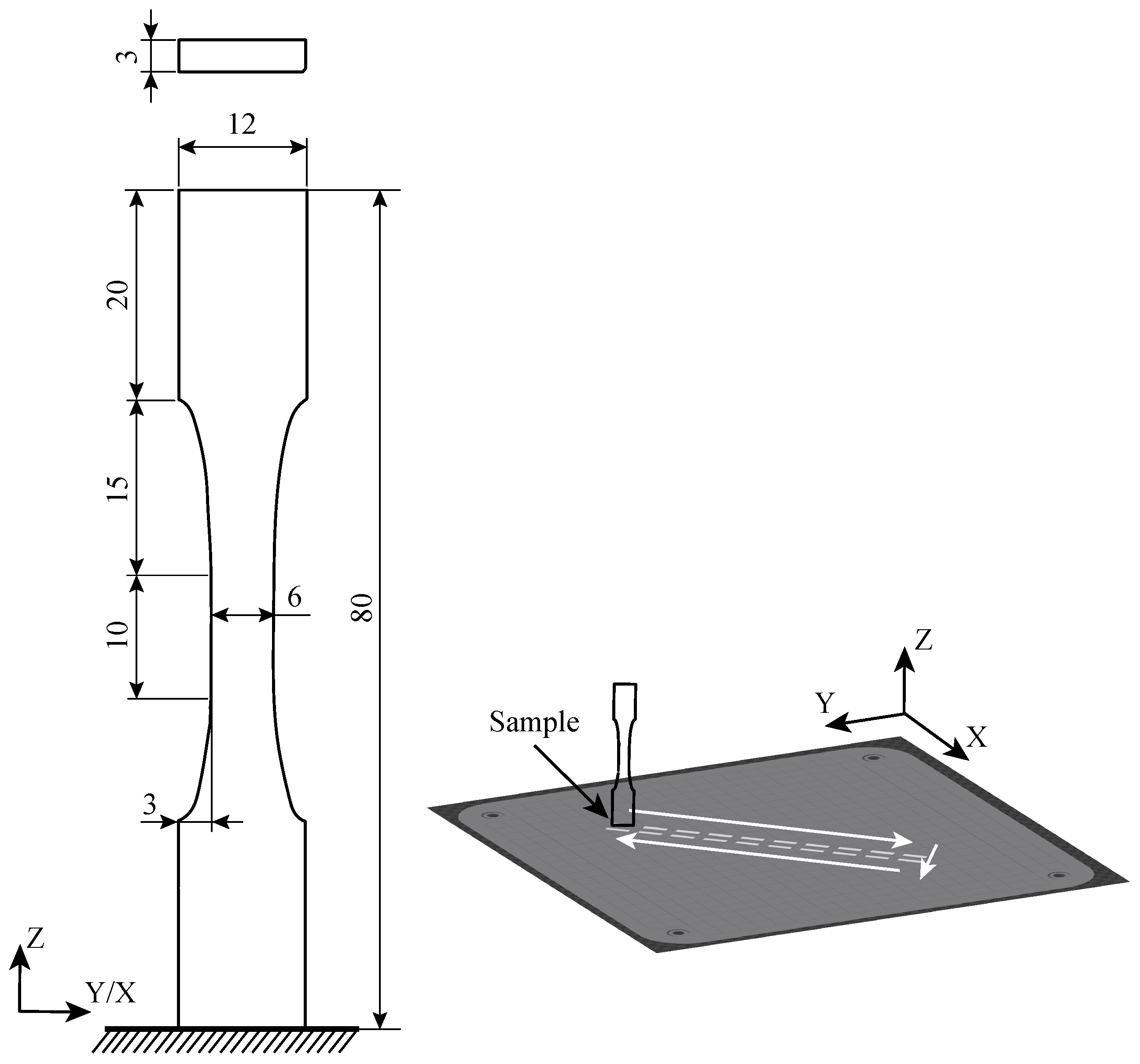
2.1. Material and Geometry

The specimens were produced using the SLM technique employing a titanium-based alloy, Ti-6Al-4V. The dimensions of the specimen are indicated in Figure 1. Note that the build direction Z-axis is indicated, starting at the support.

2.2. Manufacturing Conditions

All the specimens were provided by the manufacturer Optimus3D (Vitoria–Gasteiz, Spain) in the same orientation. The SLM parameters selected are detailed in Table 1. Three different batches of additively manufactured Ti-6Al-4V samples were produced with the following purposes:
Batch 1: Porosity characterization. Fourteen specimens were fabricated with 7 different velocities to evaluate their influence on the porosity (2 samples per velocity): {800, 1100, 1200, 1300, 1500, 1700, 1900} mm/s.
Batch 2: Tensile characterization. Two specimens were manufactured with laser velocities of 1200 and 1900 mm/s (1 sample per velocity) for tensile characterization of the material.
Batch 3: Fatigue characterization. Fifteen specimens were manufactured with laser velocities of 1200 (7 samples) and 1900 mm/s (8 samples) for fatigue characterization.

2.3. Testing and Characterization Procedures

2.3.1. Porosity Measurement Procedure

The samples from Batch 1 were sliced using a diamond disc cutter by removing a layer thickness of no less than 1 mm, in order to avoid the effect of the cutting process on the microstructure. Silicon carbide papers with different grades of 80, 240, 600, 1200 and 2500 (in this order) were used for the grinding with a continuous water stream for flushing the loose and abrasive particles. Then, a manual polishing process was applied to the surfaces using a diamond suspension of 9, 3 and 1 microns of particle size on a Remet LS1.
It is worth mentioning that neither the heat treatment nor the machining process were conducted on specimens before the experimental campaign, since the aim of this work was to study only the laser velocity, that is, without any additional varying concomitant effect that could mislead the interpretation of the experimental results. After that, the porosity was qualitatively analysed using both optical and scanning electron microscope (SEM). The entire surface of the specimens was analyzed with a resolution of 500 μm in order to identify the zones with larger pores. After that, different scanning zooms (10 and 50 μm) were applied to focus on the zones where pores had been observed. In cases where the resolution of 500 μm was not enough to identify pores in any part of the specimen, 50 μm was used to check the entire surface. It is important to remark that smaller pores could not be identified by the applied resolution. Still, the authors assumed that the influence of those pores on the fatigue life could be disregarded, compared to the pores identified in this study.

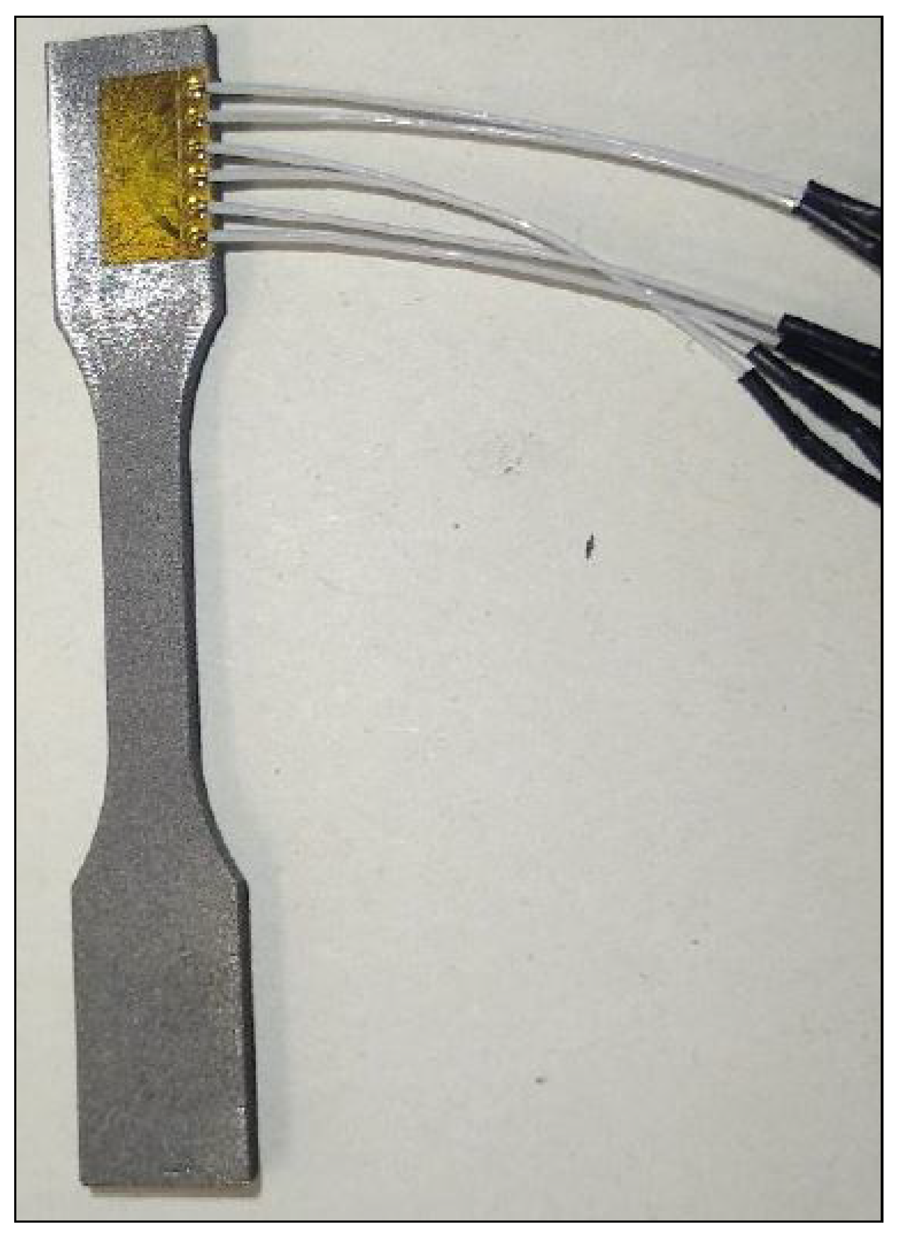
2.3.2. Residual Stresses Measurement Procedure

The measurement of the residual stresses was performed by way of the hole drilling strain gage method according to ASTM E837–13a [32] using an MTS-300 RS measurement machine supplied by SINT Technology, as can be seen in Figure 2. The parameters selected included a drilling speed of 0.2 mm/min, a drill delay of 2–3 s and an acquisition delay set to 5–10 s. The RESTAN software (SINT Technology) was used to obtain the residual stresses.

2.3.3. Tensile and Fatigue Characterization Procedure

The tensile tests were developed according to EN 2002 [33]. A strain rate of 0.05 mm/min was used for yield stress σ y s at 0.2 % and 2 %/min for tensile strength σ r . The displacement was measured using DIC equipment.
The fatigue tests were conducted for sinusoidal load at R = 0.1 and at ambient temperature, according to ASTM E466-07 [34], at a frequency of 6 Hz with stress ranging from 100 to 600 MPa, in a servohydraulic MTS Bionix. As previously mentioned, a total of 7 samples were tested for laser velocity v = 1200 mm/s and 8 samples for laser velocity v = 1900 mm/s.

3. Study of Porosity and Residual Stresses

This section presents the results obtained from numerical and experimental studies related to the estimation and measurement of specimens porosity and residual stresses.

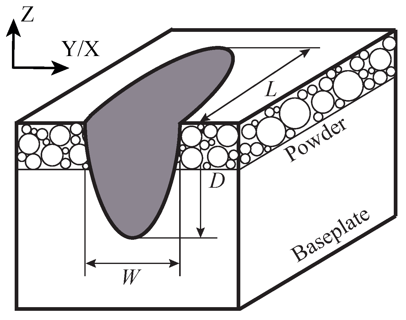
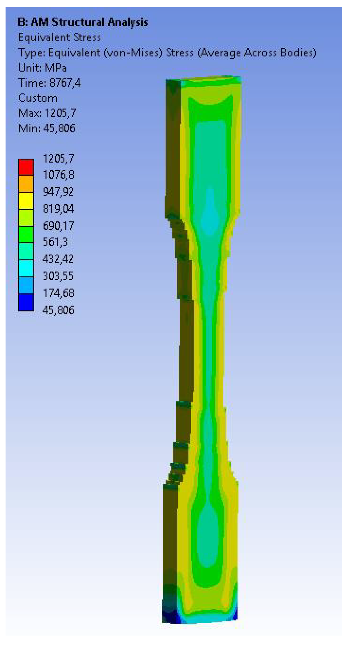
3.1. Numerical Study: Expected Porosity and Residual Stresses

Two different numerical studies were conducted: a porosity simulation for each of the different laser velocities considered in Batch 1, and a finite element simulation for the estimation of the residual stresses.
In the first case, the tool known as “Additive Science”, from the Additive Suite developed by ANSYS [35], was used to simulate the expected porosity with different laser velocities. The following constraints in the dimensions of the melt pool were introduced as an input (see Figure 3):
Reference depth ( D 0.045 ). It ensures that half of the third layer is passed in the material fusion.
Ratio depth/width ( D / W < 0.95 ). It ensures the depth is nearly the same as the width.
Ratio length/width ( L / W < 4 ). It ensures the length is not larger than the width.
Based on the constraints on the melt pool, the geometrical mean results provided by Additive Science for each velocity are summarised in Table 2.
Once the dimensions of the melt pool had been estimated, the software provided the expected porosity for each of the different laser velocities considered, as shown in Table 3, together with the corresponding energy density in the SLM process. The porosity was directly estimated by ANSYS as a function of the energy density applied, which depends on the power, velocity and the dimensions of the melt pool. It is also worth mentioning that this software only considered the porosity that was due to a lack of fusion, which was predominant at high velocities, and the porosity that was due to spherical vaporization was discarded. Then, in order to identify the kind of porosity to be experimentally found, the causal relationship between the energy density and the kind of porosity proposed by Dilip et al. [36] was used: spherical pores correspond with energy density >60 J/mm 3 , a lack of pores (or completely net) corresponds with energy density in the interval 55–60 J/mm 3 and sharper pores correspond with energy density <55 J/mm 3 . Then, according to these limits, only the velocity 800 mm/s was expected to produce spherical pores, but with a lower percentage of porosity. On the contrary, those velocities higher than 1300 mm/s were expected to give sharper pores, with the porosity percentage increasing as much as the velocity increases. According to the simulation performed and the results obtained, middle velocities ranging from 1100 to 1200 were not expected to produce pores, but completely net structures. Finally, it is worth mentioning that the values reported in Table 2 regarding the percentage of porosity are not related to experimental measurements, but to results obtained by the Additive Suite tool developed by ANSYS, in combination with the work reported by Dilip et al. [36], which studied the influence of processing parameters on the evolution of melt pool and porosity in Ti-6Al-4V alloy parts fabricated by selective laser melting.
In the second case, the Additive Science tool allowed the residual stress to be numerically simulated, as can be seen in Figure 4, where the equivalent von Mises stress is depicted along the sample.

3.2. Experimental Results
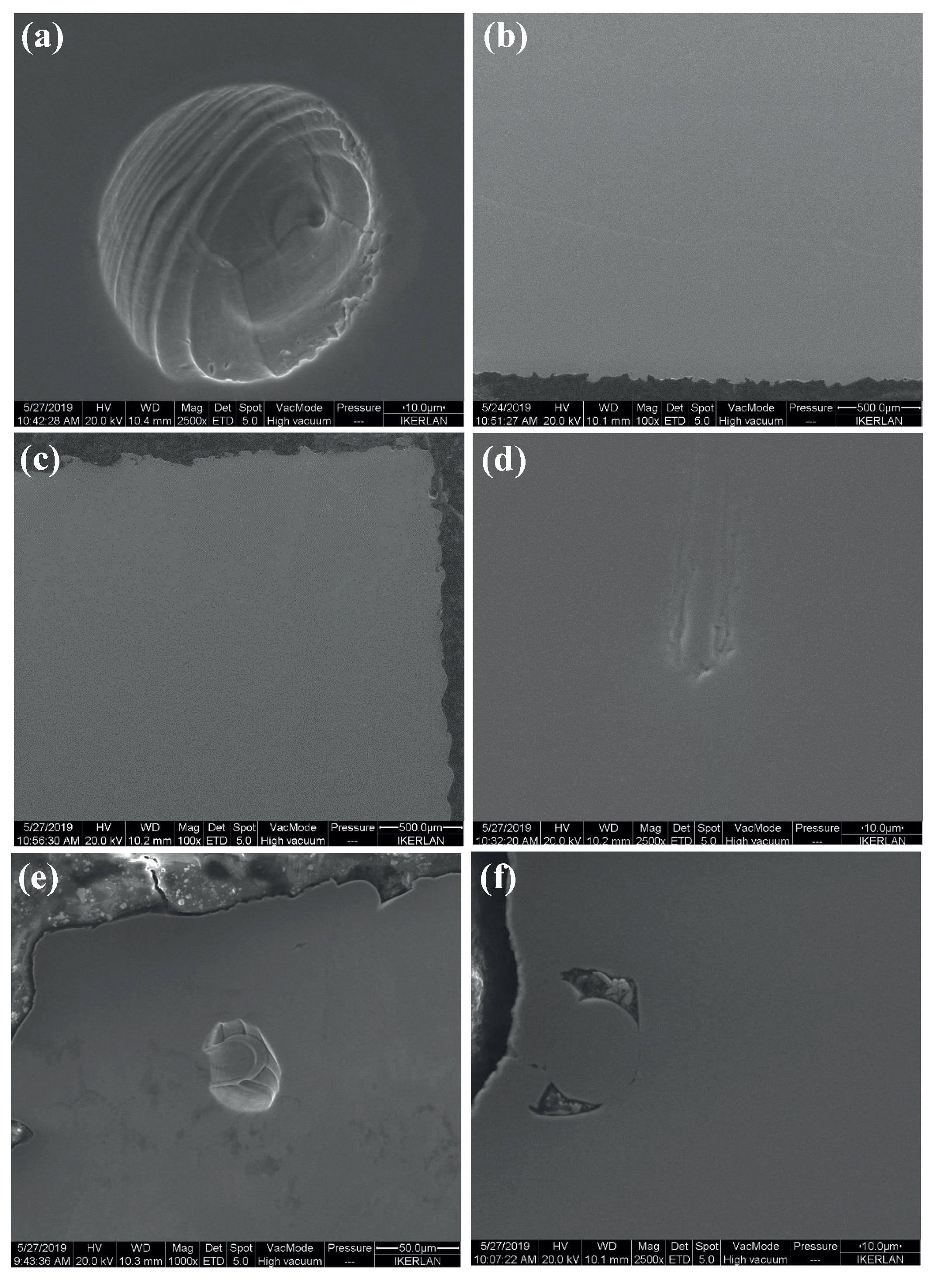
3.2.1. Porosity

The porosity was qualitatively analysed using both optical and scanning electron microscopes (SEM) for each of the laser speeds considered in Batch 1, as can be seen in Figure 5. As is well known, the geometrical forms of the pores are expected to be heterogeneous depending on the laser velocity, which occurred in this case; ranging from spherical (Figure 5a) at low velocities and high laser power, to irregular and sharper (Figure 5d–f) for large velocities and low laser power, which is in accordance with the simulated results in Section 3.1. The former are known to be caused due to improper settings or processing parameters [12,37,38], while the latter are usually related in the literature to the argon gas entrapped during the manufacturing process [39,40,41]. Furthermore, the middle velocities were expected to produce a negligible porosity in comparison with the other velocities (see Table 2), which is corroborated in the micrographs in Figure 5b,c).

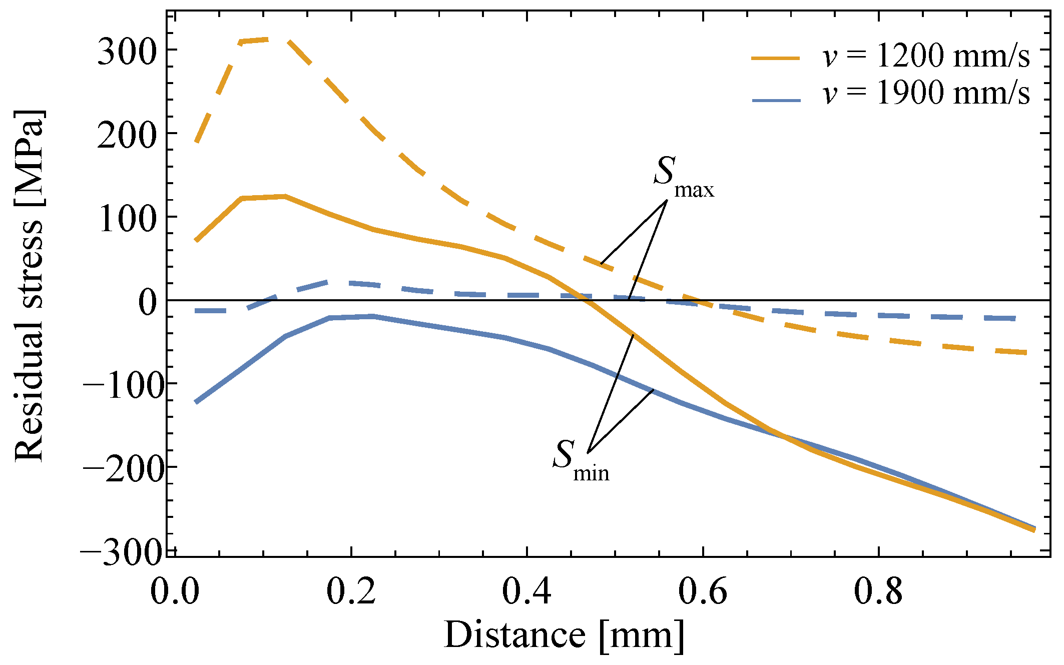
3.2.2. Residual Stress Measurement

Figure 6 illustrates the experimental results of the maximum and minimum residual stresses along the distance for both velocities considered in Batch 1. The maximum values of the residual stresses for the higher velocity evolve steadily along the distance, while for the lower velocity, a peak is present at the 0.1 mm distance. The same behaviour is observed in the case of minimum residual stress but at a lower order of magnitude. In general terms, there is an inverse trend between the development of residual stresses and the laser speed, that is, the values for both maximum and minimum residual stresses are higher for the larger velocity until a certain distance of almost 0.6 mm, where both trends tend to be equal.

4. Study of Tensile and Fatigue Behaviour

Once the study of the expected porosity and residual stresses and its comparison with the experimental results was performed, the tensile and fatigue characterization was conducted, and is now described in this section.

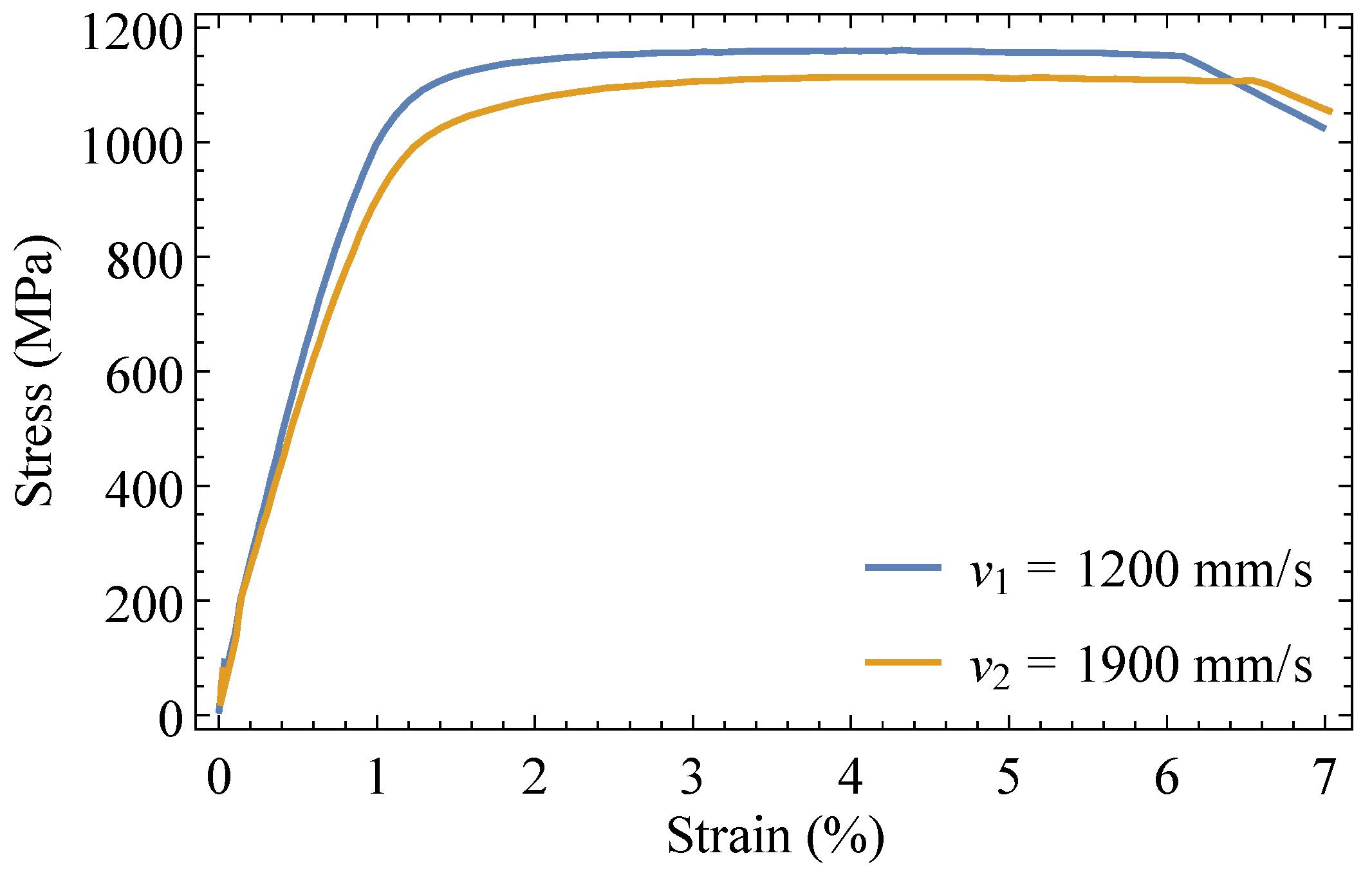
4.1. Tensile Behaviour

Engineering stress–strain curves for both velocities considered in Batch 2 are illustrated in Figure 7. As can be seen, the linear-elastic regime is approximately the same in both cases, but with a larger yield strength the lower the laser speed. In the plastic zone, however, the samples manufactured at a lower laser velocity produce a better tensile performance for the same strain value. Table 4 summarises the mechanical constants of the additively manufactured specimens for both velocities.

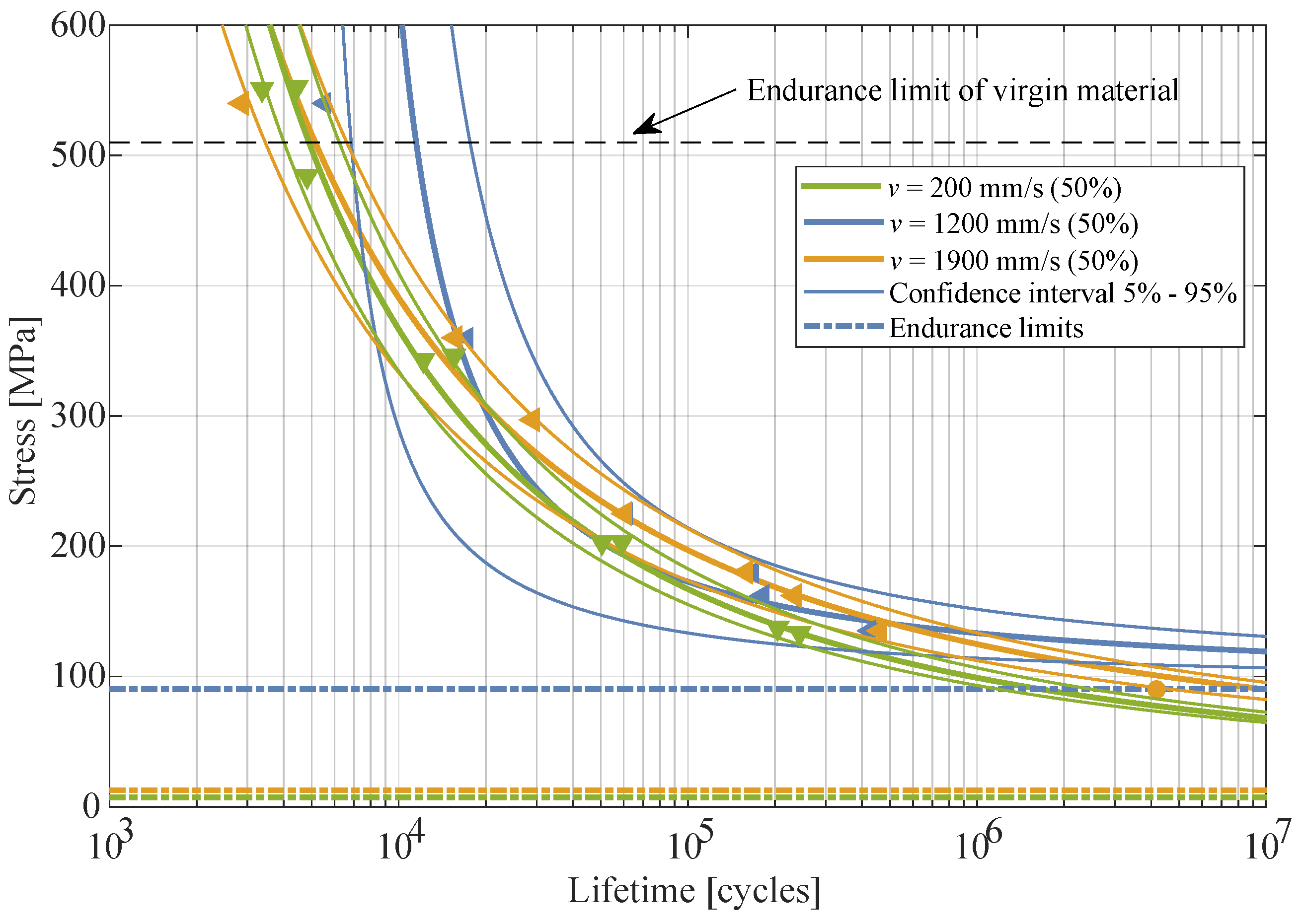
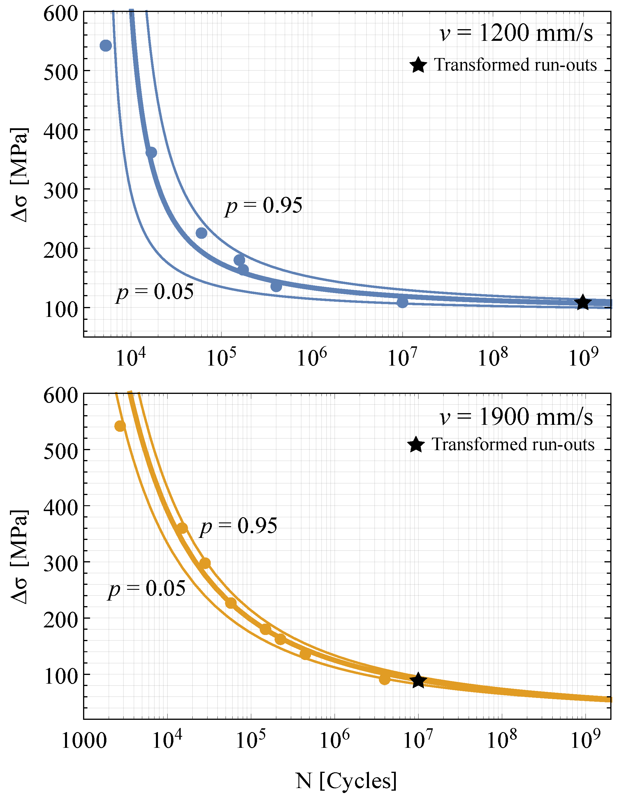
4.2. Fatigue Behaviour

Finally, the fatigue assessment of manufactured Ti-6Al-4V samples from Batch 3 was conducted according to the probabilistic model developed by [23]. In this model, the p-percentile curves in the S–N field are given as the following Weibull distribution:
p = 1 exp ( log Δ σ C ) ( log N B ) λ δ β ,
with B as the horizontal asymptote for the stress, that is, the fatigue strength, C as the vertical asymptote for the lifetime, that is, no fatigue failure will occur below this limit, and λ , δ and β as the location, scale and shape Weibull parameters, such that ( log Δ σ C ) ( log N B ) > λ .
Figure 8 depicts the estimated S–N fields for both velocities considered in this batch, which were estimated easily with ProFatigue software [42]. As can be seen, the inherent scatter of fatigue results is non-negligible, thus a probabilistic model is more suitable than a deterministic one. The fatigue performance on both velocities exhibits the same behaviour with no differences in the lifetime cycle for different given stress ranges, and the scatter bands are approximately similar. For this reason, speed manufacturing seems to not have a significant effect on the fatigue performance of additively manufactured Ti-6Al-4V.
Finally, the experimental campaign retrieved from [6], corresponding with a lower laser velocity of v = 200 mm/s, was also estimated according to the Castillo–Canteli model and is superposed in Figure 9 for comparison purposes. As a result, a wide range of laser speeds were considered from 200 to 1900 mm/s, providing robustness to the final conclusions drawn from this work. Indeed, though having a lower laser velocity, the resulting S–N field is approximately the same with both previous velocities at 1200 and 1900 mm/s, enhancing the conclusion that there was a negligible effect on the fatigue performance.

5. Discussion

In this work, different laser speeds were considered in additively manufactured Ti-6Al-4V alloy to evaluate their influence on the fatigue performance, where any other additional concurrent effect was avoided (heat treatment, machining surfaces, etc.). The experimental fatigue results were estimated according to a probabilistic model developed by [23], and the resulting S–N curves were approximately the same with the scatter bands being nearly coincident. In other words, the laser speed effect is negligible and no influence is found on the fatigue lifetime of Ti-6Al-4V specimens. Then, in order to enhance this conclusion, an external experimental campaign retrieved from [6]—at a lower velocity from those previously considered, that is, v = 200 mm/s—was also estimated and compared with previous results. Though having a wide range of laser velocities, from 200 to 1900 mm/s, the resulting S–N fields are approximately the same and the scatter bands are nearly coincident. However, this evidence does not allow for the conclusion that the effect of laser speed is negligible in terms of the fatigue lifetime of the specimens, since other concurrent effects could be covering the effects associated with the laser velocity and misleading the conclusions. The authors postulate that the high surface roughness obtained in the additive manufacturing process ( R a = 3.27 , R z = 15.83 ), together with the few differences in porosities depending on both laser speeds, lead to all cracks originating from the surfaces of the specimens, misleading conclusions about the potential effects of the porosities on the fatigue lifetime. Future work could consider the prior polishing of the specimens in order to improve the surface roughness, thus inducing the failure to occur from the pores.
The authors want to remark that the tensile and fatigue properties presented in this paper are related to only one SLM building direction. Taking into account that the material properties of metals manufactured by SLM cannot be considered isotropic—that is, dependent on the testing direction—the conclusions of this paper must be taken into consideration only for the manufacturing direction in which the specimens were made, since different results could be achieved for other directions. Furthermore, the relationship between speed manufacturing and the resulting mechanical properties is not straightforward in additively manufactured samples, as other variables are implied, such as the melt pool depth and temperature required for complete melting or evaporation; the effects of these variables were not considered in this study but are proposed as the basis for further work.

6. Conclusions

The experimental values of the residual stresses increase for lower laser speeds for both maximum and minimum values.
The expected porosity was simulated for different laser velocities, establishing limiting energy densities to identify the kind of pores: spherical, sharper or absent.
The porosity was qualitatively analysed for seven different velocities, corroborating that, for lower speeds, the pores are spherical while for larger speeds they are sharper and more irregular. On the contrary, for middle velocities no pores were detected.
Tensile experimental results at two different laser speeds showed an influence on the mechanical properties of Ti-6Al-4V alloys, especially in the plastic regime.
A probabilistic model was used to estimate the fatigue lifetime for two different velocities, concluding that this effect is negligible in comparison with other concurrent variables, such as surface defects or roughness.
The influence of speed manufacturing will only be non-negligible when other concurrent effects, such as those caused by the machining process or heat treatments, are softened or relaxed.

Author Contributions

Conceptualization, U.S., M.M.-C., Í.U. and H.N.; methodology, U.S., M.M.-C., Í.U. and H.N.; software, U.S., M.M.-C. and H.N.; validation, M.M.-C. and A.Á.-V.; formal analysis, U.S., M.M.-C. and A.Á.-V.; investigation, U.S., M.M.-C. and Í.U.; resources, U.S., Í.U. and H.N.; data curation, U.S. and H.N.; writing—original draft preparation, U.S. and A.Á.-V.; writing—review and editing, A.Á.-V., U.S. and M.M.-C.; visualization, A.Á.-V. and M.M.-C.; supervision, All authors; project administration, I.U. and M.M.-C.; funding acquisition, U.S. and Í.U. All authors have read and agreed to the published version of the manuscript.

Funding

This research received no external funding.

Institutional Review Board Statement

Not applicable.

Informed Consent Statement

Not applicable.

Data Availability Statement

Not applicable.

Conflicts of Interest

The authors declare no conflict of interest.

References

  1. ASTM F2792-12a. Standard Terminology for Additive Manufacturing Technologies; Technical Report; American Society for Testing and Materials: Philadelphia, PA, USA, 2012. [Google Scholar]
  2. Choi, D.S.; Lee, S.H.; Shin, B.S.; Whang, K.H.; Song, Y.A.; Park, S.H.; Jee, H.S. Development of a direct metal freeform fabrication technique using CO2 laser welding and milling technology. J. Mat. Proc. Technol. 2001, 113, 273–279. [Google Scholar] [CrossRef]
  3. Thompson, S.M.; Bian, L.; Shamsaei, N.; Yadollahi, A. An overview of direct laser deposition for additive manufacturing; part i: Transport phenomena, modeling and diagnostics. Addit. Manuf. 2015, 8, 36–62. [Google Scholar] [CrossRef]
  4. Huang, Y.; Leu, M.C. Frontiers of Additive Manufacturing Research and Education; Technical Report; University of Florida: Gainesville, FL, USA, 2016. [Google Scholar]
  5. Gibson, I.; Rosen, D.; Stucker, B. Additive Manufacturing Technologies. Rapid Prototyping to Direct Digital Manufacturing, 3rd ed.; Springer: Berlin/Heidelberg, Germany, 2021. [Google Scholar]
  6. Edwards, P.; Ramulu, M. Fatigue performance evaluation of selective laser melted Ti-6Al-4V. Mater. Sci. Eng. A 2014, 598, 327–337. [Google Scholar] [CrossRef]
  7. Edwards, P.; O’Conner, A.; Ramulu, M. Electron Beam Additive Manufacturing of Titanium Components: Properties and Performance. J. Manuf. Sci. Eng. 2013, 135, 061016. [Google Scholar] [CrossRef]
  8. Sreenivasan, R.; Goel, A.; Bourell, D.L. Sustainability issues in laser-based additive manufacturing. Phy. Proc. 2010, 5, 81–90. [Google Scholar] [CrossRef] [Green Version]
  9. Boyer, R.R. An overview on the use of titanium in the aerospace industry. Mater. Sci. Eng. 1996, 213, 103–114. [Google Scholar] [CrossRef]
  10. Peters, M.; Kumpfert, J.; Ward, C.H.; Leyens, C. Titanium alloys for aerospace applications. Adv. Eng. Mater. 2003, 5, 419–427. [Google Scholar] [CrossRef]
  11. Banerjee, D.; Williams, J.C. Perspectives on titanium science and technology. Acta Mater. 2013, 61, 844–879. [Google Scholar] [CrossRef]
  12. Boyer, R.R. A review of the fatigue properties of additively manufactured Ti-6Al-4V. JOM 2018, 70, 349–357. [Google Scholar]
  13. Abe, F.; Osakada, K.; Shiomi, M.; Uematsu, K.; Matsumoto, M. The manufacturing of hard tools from metallic powders by selective laser melting. J. Mater. Process. Technol. 2001, 111, 210–213. [Google Scholar] [CrossRef]
  14. Santos, E.C.; Shiomi, M.; Laoui, T.; Osakada, K. Rapid manufacturing of metal components by laser forming. Int. J. Mach. Tools. Manuf. 2006, 46, 1459–1468. [Google Scholar] [CrossRef]
  15. Kürnsteiner, P.; Wilms, M.; Weisheit, A.; Barriobero-Vila, P.; Gault, B.; Jägle, E.; Raabe, D. In-process precipitation during laser additive manufacturing investigated by atom probe tomography. Microsc. Anal. 2017, 23, 694–695. [Google Scholar] [CrossRef] [Green Version]
  16. Simonelli, M.; McCartney, D.G.; Barriobero-Vila, P.; Aboulkhai, N.T.; Tse, Y.Y.; Clare, A.; Hague, R. The influence of iron in minimizing the microstructural anisotropy of Ti-6Al-4V produced by laser powder-bed fusion. Metall. Mater. Trans. A 2020, 51, 2444–2459. [Google Scholar] [CrossRef] [Green Version]
  17. Nalla, R.K.; Ritchie, R.O.; Boyce, B.L.; Campbell, J.P.; Peters, J.O. Influence of microstructure oon high-cycle fatigue of Ti-6Al-4V: bimodal vs. lamella structures. Metall. Mater. Trans. A 2002, 33, 899–918. [Google Scholar] [CrossRef]
  18. Thijs, L.; Verhaeghe, F.; Craeghs, T.; VanHumbeeck, J.; Kruth, J.P. A study of the microstructural evolution during selective laser melting of Ti-6Al-4V. Acta Mater. 2010, 58, 3303–3312. [Google Scholar] [CrossRef]
  19. Edwards, P.; Ramulu, M. Effect of build direction on the fracture toughness and fatigue crack growth in selective laser melted Ti-6Al-4V. Fatigue Fract. Eng. Mater. Struct. 2015, 38, 1228–1236. [Google Scholar] [CrossRef]
  20. Van Zyl, I.; Yadroitsava, I.; Yadroitsev, I. Residual stresses in Ti6Al4V objects produced by direct metal laser sintering. Addit. Manuf. 2016, 27, 134–141. [Google Scholar]
  21. Ali, H.; Ma, L.; Ghadbeigi, H.; Mumtaza, K. In-situ residual stress reduction, martensitic decomposition and mechanical properties enhancemente through high temperature powder bed pre-heating of selective laser melted Ti6Al4V. Mater. Sci. Eng. A 2017, 695, 211–220. [Google Scholar] [CrossRef]
  22. Günther, J.; Krewerth, D.; Lippmann, T.; Leuders, S.; Tröster, T.; Weidner, A.; Biermann, H.; Niendorf, T. Fatigue life of additively manufactured Ti-6Al-4V in the very high cycle fatigue regime. Int. J. Fatigue 2017, 94, 236–245. [Google Scholar] [CrossRef]
  23. Castillo, E.; Fernández-Canteli, A. A Unified Statistical Methodology for Modeling Fatigue Damage; Springer: Dordrecht, The Netherlands, 2009. [Google Scholar]
  24. Spierings, A.B.; Starr, T.L.; Wegener, K. Fatigue perfomance of additive manufactured metallic parts. Rapid Prototyp. J. 2013, 19, 88–94. [Google Scholar] [CrossRef]
  25. Kasperovich, G.; Hausmann, J. Improvement of fatigue resistance and ductility of TIAl6V4 processed by selective laser melting. J. Mater. Process. Technol. 2015, 220, 202–214. [Google Scholar] [CrossRef]
  26. Walker, K.F.; Liu, Q.; Brandt, M. Evaluation of fatigue crack propagation behaviour in Ti-6Al-4V manufactured by selective laser melting. Int. J. Fatigue 2017, 104, 302–308. [Google Scholar] [CrossRef]
  27. Le, V.; Pessard, E.; Morel, F.; Edy, F. Influence of porosity on the fatigue behaviour of additively fabricated Ta6V alloys. In Proceedings of the 12th International Fatigue Congress (FATIGUE 2018), Potiers, France, 27 May–1 June 2018; Volume 165, p. 02008. [Google Scholar]
  28. Greitemeier, D.; Palm, F.; Syassen, F.; Melz, T. Fatigue performance of additive manufactured TiAl6V4 using electron and laser beam melting. Int. J. Fatigue 2017, 94, 211–217. [Google Scholar] [CrossRef]
  29. Wycisk, E.; Emmelmann, C.; Siddique, S.; Walther, F. High cycle fatigue (HCF) performance of Ti-6Al-4V alloy processed by selective laser melting. Adv. Mater. Res. 2013, 816, 134–139. [Google Scholar] [CrossRef]
  30. Leuders, S.; Thöne, M.; Riemer, A.; Niendorf, T.; Tröster, T.; Maier, H.J. On the mechanical behaviour of titanium alloy TiAl6V4 manufactured by selective laser melting: Fatigue resistance and crack growth performance. Int. J. Fatigue 2013, 48, 300–307. [Google Scholar] [CrossRef]
  31. Li, P.; Warner, D.H.; Fatemi, A.; Phan, N. Critical assessment of the fatigue performance of additivelymanufactured Ti-6Al-4V and perspective for future research. Int. J. Fatigue 2016, 85, 130–143. [Google Scholar] [CrossRef]
  32. ASTM E837-13a. Standard Test Method for Determining Residual Stresses by the Hole-Drilling Strain-Gage Method; Technical Report; American Society for Testing and Materials: Philadelphia, PA, USA, 2020. [Google Scholar]
  33. EN 2002. Aerospace Series–Metallic Materials–Test Methods–Part 1: Tensile Testing at Ambient Temperature; Technical Report; European Standards: Brussels, Belgium, 2005. [Google Scholar]
  34. ASTM E466-07. Standard Practice for Conducting force Controlled Constant Amplitude axial Fatigue Tests of Metallic Materials; Technical Report; American Society for Testing and Materials: Philadelphia, PA, USA, 2007. [Google Scholar]
  35. ANSYS. Additive Print and Additive Science User Guide; ANSYS, Inc.: Canonsburg, PA, USA, 2019. [Google Scholar]
  36. Dilip, J.J.S.; Zhang, S.; Ten, C.; Zeng, J.; Robinson, C.; Pal, D.; Stucker, B. Influence of processing parameters on the evolution of melt pool, porosity, and microstructures in Ti-6Al-4V alloy parts fabricated by selective laser melting. Prog. Addit. Manuf. 2017, 2, 157–167. [Google Scholar] [CrossRef] [Green Version]
  37. Wang, P.; Nai, M.L.S.; Aw, B.; Wei, L.J. Effect of processing parameters on microstructure and mechanical properties of Ti-6Al-4V made by selective electron beam melting additive manufacturing. In Proceedings of the Annual International Solid Freeform Fabrication Symposium (SFF Symp 2016), Austin, TX, USA, 8–10 August 2016. [Google Scholar]
  38. Wang, P.; Nai, M.L.S.; Tan, X.; Vastola, G.; Raghavan, S.; Sin, W.J.; Tor, S.B.; Pei, Q.X.; Wei, J. Recent progress of additive manufactured Ti-6Al-4V by electron beam melting. In Proceedings of the Annual International Solid Freeform Fabrication Symposium (SFF Symp 2016), Austin, TX, USA, 8–10 August 2016. [Google Scholar]
  39. Mok, S.H.; Bi, G.; Folkes, J.; Pashby, I. Deposition of Ti-6Al-4V using a high power diode laser and wire, Part I: Investigation on the process characteristics. Surf. Coat. Technol. 2008, 202, 3933–3939. [Google Scholar] [CrossRef]
  40. Tammas-Williams, S.; Zhao, H.; Léonard, F.; Derguti, F.; Todd, I.; Prangnell, P. XCT analysis of the influence of melt strategies on defect population in Ti-6Al-4V components manufactured by selective electron beam melting. Mater. Charact. 2015, 102, 47–61. [Google Scholar] [CrossRef]
  41. Carroll, B.E.; Palmer, T.A.; Beese, A.M. Anisotropic tensile behavior of Ti-6Al-4V components fabricated with directed energy deposition additive manufacturing. Acta Mater. 2015, 87, 309–320. [Google Scholar] [CrossRef]
  42. Fernández-Canteli, A.; Przybilla, C.; Nogal, M.; López-Aenlle, M.; Castillo, E. Profatigue: A software program for probabilistic assessment of experimental fatigue data sets. Procedia Eng. 2014, 74, 236–241. [Google Scholar] [CrossRef]
Figure 1. Dimensions (in mm.) of the Ti-6Al-4V specimens with build direction in Z and the support.
Metals 11 01022 g001
Figure 2. Strain gage method in hole drilling for measurement of residual stresses.
Metals 11 01022 g002
Figure 3. Dimensions of the melt pool.
Metals 11 01022 g003
Figure 4. Residual stresses simulated upon the removal of the support.
Metals 11 01022 g004
Figure 5. SEM micrographs for different laser velocities: (a) v = 800 mm/s, (b) v = 1100 mm/s, (c) v = 1200 mm/s, (d) v = 1500 mm/s, (e) v = 1700 mm/s, (f) v = 1900 mm/s.
Metals 11 01022 g005
Figure 6. Experimental values of maximum and minimum residual stresses for two different laser velocities: v = 1200 mm/s and v = 1900 mm/s.
Metals 11 01022 g006
Figure 7. Engineering stress vs. strain curves for Ti-6Al-4V for two velocities: 1200 and 1900 mm/s.
Metals 11 01022 g007
Figure 8. Resulting S–N curves from the Castillo–Canteli model for Ti-6Al-4V with velocities 1200 mm/s and 1900 mm/s.
Metals 11 01022 g008
Figure 9. Comparison of S–N fields for different laser velocities: v = 200 mm/s (data from Edwards and Ramulu [6]), v = 1200 mm/s and v = 1900 mm/s.
Metals 11 01022 g009
Table 1. SLM parameters selected.
Layer Thickness [mm]Hatch Spacing [mm]Power [W]
0.030.1200
Table 2. Numerical results of the geometrical dimensions of the melt pool for different velocities.
Scan Speed [mm/s] D ¯ [mm] L ¯ [mm] W ¯ [mm]
8000.1150.4470.157
11000.0820.4460.136
12000.0740.4420.130
13000.0670.4390.125
15000.0560.4280.115
17000.0470.4170.108
19000.0390.4000.101
Table 3. Numerical results of the porosity simulations for different velocities.
Scan Speed [mm/s]Energy Density [J/mm 3 ]Porosity [%]
80083.330.00
110060.610.00
120055.560.00
130051.280.00
150044.440.01
170039.220.08
190035.090.36
Table 4. Tensile properties for additively manufactured Ti-6Al-4V obtained from the stress–strain curves in Figure 7.
Velocity (mm/s) σ ys (MPa) σ r (MPa) ε f (%)
12001068.621158.966.12
1900990.691114.766.58
Publisher’s Note: MDPI stays neutral with regard to jurisdictional claims in published maps and institutional affiliations.

