Article

Study of Hillock and Zinc Whisker Evolution in Five Different Cable Tray Coatings

1
LADICIM, Departamento de Ciencia e Ingeniería del Terreno y de los Materiales, University of Cantabria, Avenida de los Castros, 44, 39005 Santander, Spain
2
VALDINOX Ltd., Villanueva 12, 39192 San Miguel de Meruelo, Spain
*
Author to whom correspondence should be addressed.
Metals 2021, 11(2), 325; https://doi.org/10.3390/met11020325
Submission received: 31 December 2020 / Revised: 6 February 2021 / Accepted: 9 February 2021 / Published: 13 February 2021

Abstract

:
The main objective of this work is the study of the hillock and zinc whisker evolution of five different commercial zinc coatings applied on the same base steel wires of the patented EASYCONNECT system cable trays manufactured by VALDINOX Ltd.: white zinc alkaline electrolyte, yellow zinc trivalent electrolyte, acid zinc electrolyte, hot dip galvanized, and zinc nickel coating. The limited literature on the subject is summarized, and then the coating thickness, chemical composition, hardness and surface rugosity are characterized. The hillock and whisker density evolution are evaluated over a period of 12 months, considering the presence of compression bending stresses. It is concluded that the white alkaline and yellow trivalent coatings are the most affected, while the zinc-nickel shows the best behavior with no presence of whiskers; the acid zinc electrolyte also shows good results despite the delayed appearance of whiskers from the ninth month; the hot-dip galvanized coating does not show any presence of zinc whiskers or hillocks.

1. Introduction

Steel is widely used in different fields, such as for cable trays and other components within the electronics sector. However, this metal presents oxidation and corrosion problems when in contact with the environment, so it is common practice to cover it with protective layers. The most commonly used coatings consist of paints of various types, or the application of thin layers of other metals with superior resistance to environmental phenomena, such as chromium or zinc.
Zinc coatings, electrodeposited or hot-dip galvanized, are widely used; since the 1940s, the growth of zinc whiskers and hillocks has been detected in zinc coatings in different industrial fields, but very few studies have been carried out so far. A zinc whisker is a filament emanating from the surface of a zinc-coated material, which has a hexagonal crystalline structure; there are three main types: nodular, rectilinear and with abrupt changes of direction. A hillock is a bump on the coating surface, and the place where whiskers can grow on. Hillocks consist of lumps from which whiskers may arise. The main issue lies in the fact that these small fragments of material have relatively good conducting properties.
These filaments lead to problems in facilities that have a high presence of electronic equipment, the run for the miniaturization makes the weight of this phenomenon heavier by an increase in the probability of causing short-circuits [2,3]. A simple cylindrical filament of a few micrometer in diameter, able to reach 1mm long, can cause the dysfunction of an entire data center [4], as air flows can easily lead to its detachment and drag.
There is a wide range of zinc coatings on the market, and a variety of electroplating or hot-dip galvanizing technologies are available, but no in-depth studies comparing their capacities with respect to the hillock or whisker phenomena have been carried out up to the present. In this work, a selection of five different zinc coatings are analyzed in detail. They are applied on the same base steel wires of the patented EASYCONNECT system cable trays manufactured by a leading company in the field of cable tray manufacturing, VALDINOX Ltd. [1], and make up a highly representative sample of the currently used coating technologies. The results are presented, comparing the behavior of the hillocks and behavior over 12 months in service, taking into account the presence of compression stresses, which is one of the most influential variables in this phenomenon.

2. State of the Art

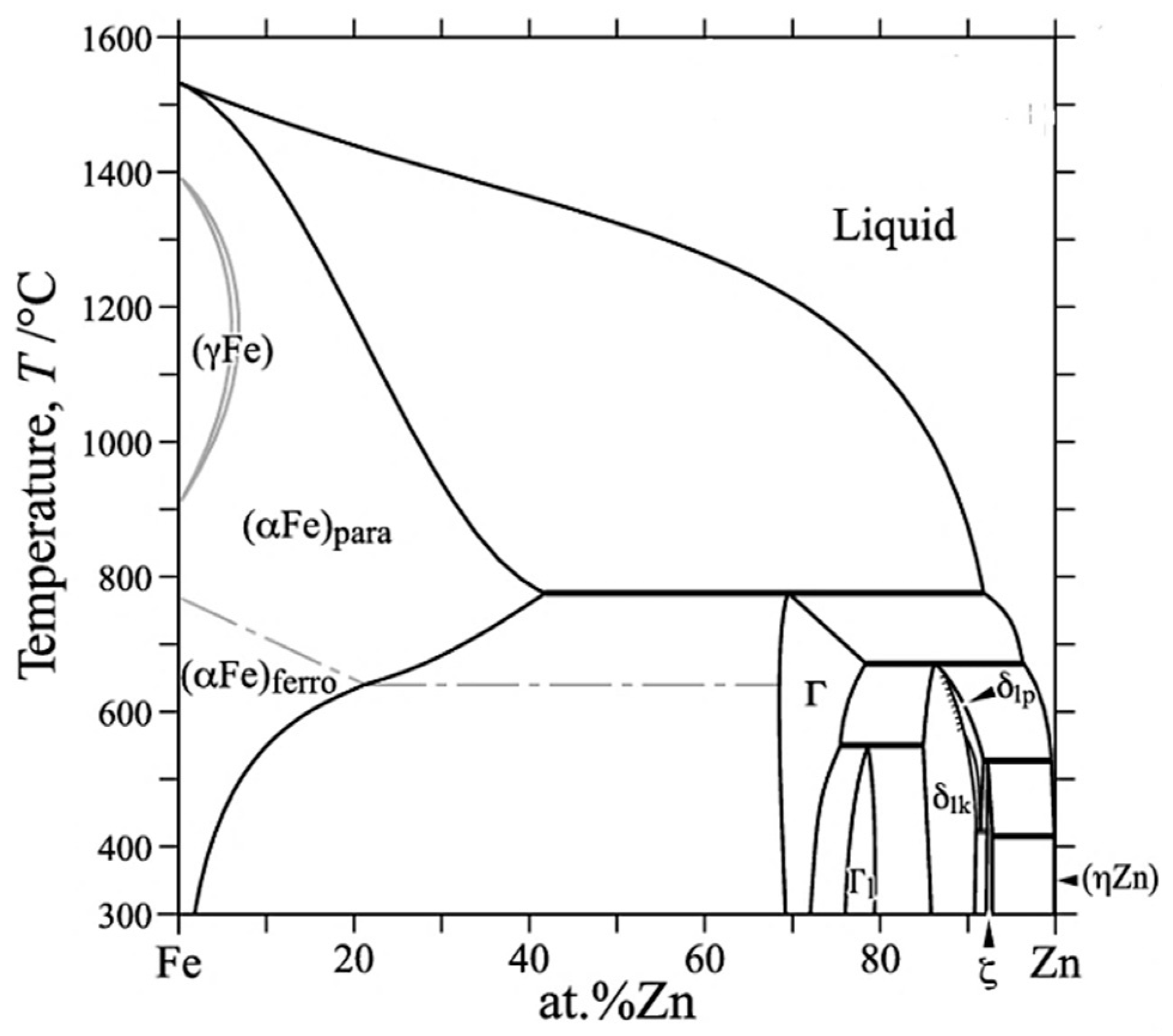
2.1. Protection of Steel with Zinc Coatings

Zinc is used to protect steel from oxidation by playing the role of a sacrificial anode; it actually forms zinc oxide, which prevents further zinc corrosion [2]. The choice of the process for zinc deposition on a steel substrate has a great influence on the formation of whiskers. Zinc has a relatively low melting point, around 420 °C. This intrinsic parameter makes it highly prone to the growth of zinc whiskers [2]. Zinc coatings can present different textures, such as alkaline electrolytes composed of trichite agglomerates, which makes them relatively porous. The oriented growth direction with this element is (0001) whereas acid electrolytes have a micro dendritic texture preferentially oriented (1122). Finally, there are coatings formed by hexagonal zinc structures characterized by their poor density of dislocations and stacking faults [2], which are sometimes called compact coatings.
There are two main processes for zinc coating application: hot dip galvanizing and electroplating. Figure 1 shows the external appearance of the two techniques in real components 10 months after fabrication.
In hot dip galvanizing, the metal substrate is immersed into a molten zinc bath; prior to this, the component is submitted to a number of pickling and rinsing steps. The resulting coating is actually composed of several metallurgical bonded layers. The coatings obtained by this process are not prone to whisker growth, according to World Environment Services [2,5]. Nevertheless, whiskers have been found in hot dip galvanized zinc coatings [6,7].
Electroplating consists in the application of an electrical current to an electrolytic solution coupled to a zinc anode, while the steel acts as cathode. Zinc, the metal to be deposited, comes from the anode (soluble anode) or from the reduction of the electrolyte with an electrical current. Electroplating has been identified to be more prone to whisker growth [2]; previous research has shown that the chromium passivation layer also has an impact on the whisker growth, increasing the incubation time but not preventing it [2].

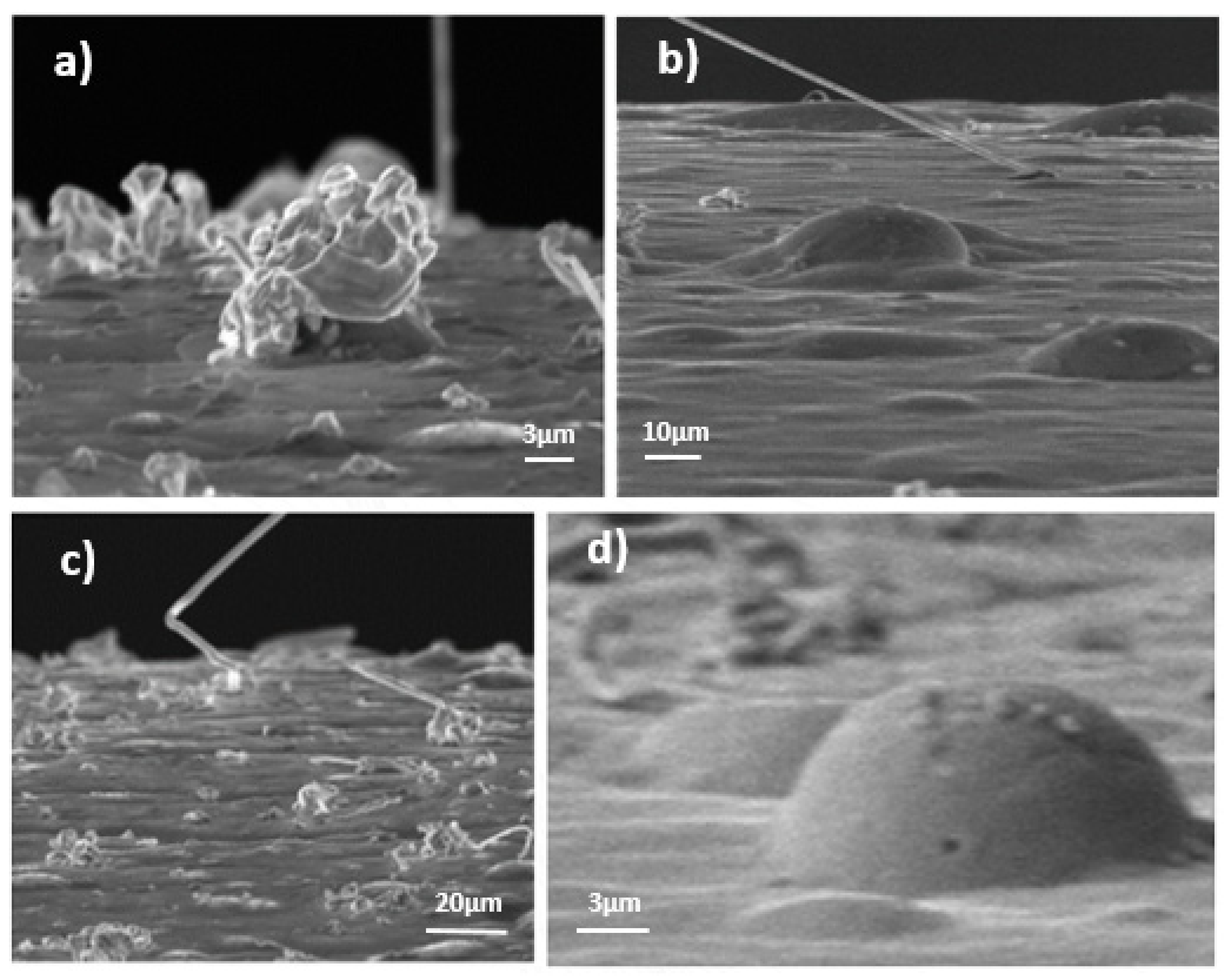
2.2. Definition and Dimensions of Zinc Whiskers (ZW) and Hillocks

A zinc whisker can be defined as a cylindrical or columnar filament emanating from the surface of a material. Bibliographic sources, although scarce, state that this cylinder is made up of a single crystal [4]. Nevertheless, the possibility of polycrystalline material in Zn is described by [8], though it is concluded that this could not be proved due to the poor quality of the images. It should also be noted that ZW have a hexagonal crystalline structure. Three different kinds of whiskers have been detected so far (Figure 2):
  • Nodular whiskers: this shape usually corresponds to the beginning of the growth.
  • Rectilinear whiskers: the most constraining kind, which can reach greater lengths. The longer the ZW is, the easier it can be broken, moved away and cause electric damage.
  • Whiskers with abrupt changes of direction.
It is necessary to describe in detail the concept of hillocks (Figure 2), as these are a part of the phenomenon. A hillock can be characterized as a bump caused by the release of a residual stress on the coating surface. The main explanation for this phenomenon is the mismatch of the thermal coefficient between the coating and the iron bulk [2].
It is necessary to describe in detail the concept of hillocks (Figure 2), as these are a part of the phenomenon, and the place where whiskers can grow on. A hillock can be characterized as a bump caused by the release of a residual stress on the coating surface. The main explanation for this phenomenon is the mismatch of the thermal coefficient between the coating and the iron bulk [2].
By X-ray diffraction analysis, Compton et al. [9] and Takemura et al. [10] determined that zinc whiskers are not compounds, but metallic filaments in the form of single crystals. Zinc has a hexagonal crystalline structure. The orthogonal axis is parallel to the filament.
Several authors [11,12] have observed recrystallized zinc in the zinc electroplate, with columnar grains extending in a direction perpendicular to the surface. Others [13,14] found that a zinc coating has a structure of small grains between the electroplated zinc and the root of a rectilinear whisker. No thinning of the coating was observed, even around the whisker root.
Electroplated zinc coatings on a steel substrate, with low process temperatures, do not show intermetallic compounds (IMC) at the scale of SEM observations; the solubility limit of iron in zinc is very low (<0.03% at 450 °C according to the Fe-Zn phase diagram presented in Figure 3) [2]. Nevertheless, IMC does form rapidly in hot dip galvanizing processes when the temperature is high [13]. The assessment of the behavior of Zn electrodes in alkaline electrolyte reported in the literature by Minakshi et al. provides a useful insight into the behavior of Zn in different applications [15,16,17].
Baated et al. [18] stated that zinc oxides and Fe–Zn intermetallic compounds are a key source of compressive stress in zinc coatings. Zinc reacts with the iron diffused from the substrate and with the oxygen diffused from the environment, producing an IMC and oxide layer, respectively. Both the oxide and the IMC can be a source of compressive stress on zinc grains, which actually diffuse to the surface of the coating forming the whiskers. This compressive stress then becomes the driving force of the zinc whisker growth [2].

2.3. Zinc Whisker Growth Phenomenon

The growth of whiskers can be described as a two-stage phenomenon. It begins with a period of incubation, known as “incubation time”, which can last from a few months to several years. It has been shown that the incubation time is inversely proportional to the stress, and that there is a dependence of the growth rate on the whiskers’ length [2]. The second stage corresponds to the growth of the whisker and can, in certain cases, reach a rate of 1 mm/year. The first important discovery and validated hypothesis was the fact that whiskers grow from their base and not from their edges [2,19].
Several models have been elaborated in order to be able to accurately describe the phenomenon. Frank [19] proposed a model based on the rotation of a right-angle edge-screw dislocation that adds an additional plane to the whisker base after each revolution. Eshelby [20] states that surface tractions tend to pull out a whisker, while providing a constraining collar at the root which keeps the diameter constant. Lindborg concluded that for each metal atom leaving the electroplate, there should be a corresponding vacancy formed somewhere below the root of the whisker [21]. As holes have never been seen in electroplating, diffusion must take place over long distances compared to the diameter of the whisker. Therefore, he proposed a model for zinc whisker growth [22], consisting of a long-distance diffusion stage (where a climbing dislocation loop acts as a vacancy-emitting source) and a glide stage (where dislocations glide to the surface).
Mechanisms proposed by Eshelby, Franks and Lindborg are based on creep diffusion at the grain boundaries. A total of two creep mechanisms are considered: bulk or lattice diffusion (NabarroHerring creep) and grain boundary diffusion (Coble creep), as well as a combined diffusion (bulk diffusion plus grain boundary diffusion) [2,23]. According to [2], a new half plan of atom would stand out each time a loop is emitted. The surface is subjected to oxidation, so the interface energy has to be negative; there is tensile stress. This stress tends to pull out the whisker. In order for the growth to be possible, a stress threshold needs to be crossed. At values close to the threshold, growth is driven by the glide and there is a significant increase in slip rate, creating a linear dependence on stress. Spontaneous whisker growth has been observed mainly in electroplated coatings of low melting point metals, where the recrystallization temperature is under room temperature, such as cadmium, zinc and tin [2]. Based on this, Ellis et al. [24] concluded that dislocations could not explain their experimental observations, so they suggested recrystallization as a mechanism of whisker growth, a hypothesis that was later supported by Glazunova and Kudryavtsev [25], Kakeshita et al. [26], Le-bret et al. [27] and Boguslavsky and Bush [28], among other authors.
The recrystallization mechanism is widely accepted today by the scientific community [2]. However there are different approaches or models. The two main recrystallization mechanisms [2], proposed by Smetana in 2007 [29] and Vianco and Rejent in 2009 [30], have been elaborated for tin whiskers but they can also be correlated to zinc whiskers.
According to this theory, the ZW base is subjected to compressive stress. Close to the surface we can find recrystallized grains. These new grains are separated from each other by two different types of grains boundaries: columnar and oblique grain boundaries; the latter are submitted to lower stresses. The atomic density in the grain boundaries is lower than anywhere else in the material, which allows easier movements. As all the material is submitted to the same force, a difference in the atom density tends to create a stress gradient.
Smetana [29] proposed that the atoms at the grain boundary in the whisker base are averagely at a lower energy (compressive stress) level than the surrounding areas, which allows the movement of atoms. Grain boundaries are actually sites with a lower degree of order and atom packing density. This theory considers compressive stress in the coating as the driving force for the whisker growth. As shown in [29], this mechanism is based on the columnar grain boundaries observed at the electroplate, where the grain boundary interfaces are subjected to biaxial compressive stress (σ) at the plane of the coating, resulting from a force (F). After recrystallization of new grains, oblique grain boundaries are formed in the coating. Compressive stress in oblique grain boundaries is lower than in vertical grain boundaries, although the applied force is equal, which leads to stress gradients in the grain boundaries, necessary for diffusion to the base of the whisker growth. Additionally, there is a lower atomic packaging density in the grain boundaries, leading to a stress gradient between the grain boundary and the bulk tin grain. The components of the stress applied to the oblique grain boundaries result in shear stress, parallel and perpendicular to the grain boundary.
Vianco and Rejent [30] stated that compressive stress does not explicitly cause whisker growth through the bulk movement of the material. Rather, compressive stress generates inelastic deformation and, thus, an increase in strain energy that initiates DRX, which is actually the source of the whisker growth from the surface. Dynamic recrystallization (DRX) is an enhancement of the static recrystallization caused by the simultaneous occurrence of deformation. In contrast, static recrystallization occurs when the strain energy of defective structures is reduced without additional deformation occurring at the same time. The slower the strain rate, the more likely it is for the deformation (strain energy build-up) and recrystallization (strain energy loss) processes to overlap (DRX). According to the authors, the DRX model requires two processes: first, the deformation mechanism that initiates DRX and second, the mass transport mechanism that sustains grain (whisker) growth.
The steps of the DRX model for whisker growth, illustrated in [30], are as follows: (a) the compressive stress leads to the creation of dislocations, which pile up at pre-existing grain boundaries; (b) the resulting strain energy increases to the point where new grains are initiated as the DRX grain refinement step described above (whisker does not grow from a pre-existing grain; therefore the new grain, and thus the whisker grain orientation, does not need to correlate exactly to the texture of the nearby grains); (c) the new grain grows by migration of grain boundaries, although the size of the new grain is limited to the size of the already existent grains, which corresponds to the thickness of the electrodeposited film in the case of coatings; (d) the strain continues under the action of the compressive stress, producing a driving force in order to reduce the energy of the system: at this point, the whisker growth starts, and since no further growth is possible in the coating, the grain has to grow outside, from the surface with a whisker shape.
While these recrystallization mechanisms are proposed for tin whiskers, recrystallized grains have been also observed in zinc electroplates in recent experiments. Etienne et al. [31] analyzed a whisker root on a zinc electroplated steel by EBSD; the zinc coating was found to be formed by columnar grains, while the grains at the root of the whisker were recrystallized.

2.4. Influencing Parameters in the Phenomenon

There are many parameters than can affect the ZW growth phenomenon, both intrinsic and environmental; the difficulty lies in the fact that these parameters are somehow already correlated. The most important influencing and non-influencing parameters, according to the information collected until 2014 by J. Cabrera-Anaya [2], are summarized in Table 1.

3. Materials and Methods

This section is divided by subheadings and aims to provide a concise and precise description of the experimental results and their interpretation, as well as the experimental conclusions that can be drawn.

3.1. Coatings under Study and Base Metal

In this work, the following five different coatings are analyzed. All of them are applied on Φ4 mm carbon steel base wires from the same manufacturer. The storage time between their fabrication and the study was of around two months.
  • White alkaline electrolyte coating (re-named coating 1 for simplicity): The sample was covered with a zinc coating electrolytic method. Prior to this, some stages of chemical preparation had been applied: Protel FR21 chemical degreasing, Uniclear H2425 electrolytic degreasing, HCl scouring, Protolux AZURE applied during 35–40 minutes, NO3H 1% neutralization and passivation and drying at temperature below 60 °C.
  • Yellow trivalent zinc electrolyte coating (re-named coating 2 for simplicity): the steps were identical to those of the white alkaline electrolyte coating, except for the passivation stage, which corresponds to the deposition of the chromium layer, which uses a different solution in this case.
  • Acid zinc electrolyte coating (re-named coating 3 for simplicity): In this case no information was supplied by the manufacturing company, VALDINOX [4].
  • Hot dip galvanizing zinc coating (re-named coating 4 for simplicity): the resulting coating is composed of several metallurgical bonded layers. Firstly, several surface preparation steps need to be carried out: degreasing with caustic solutions, rinsing, pickling with hydrochloric acid, second rinsing, oxidation protection layer (called the flux stage) and drying. Then, the galvanization step consists of immersing the studied elements in a crucible with melted zinc, where a chemical reaction takes place between the steel and the zinc that allows the creation of the coating layer; the bath composition is essentially zinc, the presence up to 1.5% of other elements being authorized. A final passivation layer is added in order to delay the formation of zinc oxide.
  • Zinc–nickel coating (re-named coating 5 for simplicity): this coating also uses an electrolyte method, but in this case a zinc–nickel one was employed according to UN UNE-EN 12,329 standard [34]. Prior to this, some stages of chemical preparation had been applied: 20% HCl scouring, water continually renewed rinsing, Uniclean 298 chemical and electrolytic degreasing, 2nd water continually renewed rinsing. Then, the Zn-Ni bath is applied and after this, two steps of water continually renewed rinsing, plus a 1% Nitric acid pre-passivation and a Cr blue passivation, to finally undergo a water continually renewed rinsing and drying in oven.
The microstructure of the base material (steel wire) was analyzed. For this purpose, sub-samples of the cross and longitudinal sections were obtained, encapsulated in Bakelite cylinders (Figure 4), polished and finally a 5% NITAL chemical attack was used (5% of nitric acid dissolved in ethanol) for 7 s on each sample. It was observed that all the coatings had been applied on the same base material, showing the ferritic-pearlitic structure presented in Figure 4; for all the samples, an anisotropy in the shape of the grains can be observed due to the cold drawn of the steel. The approximate size of the grain is between 30 and 70 µm in length.

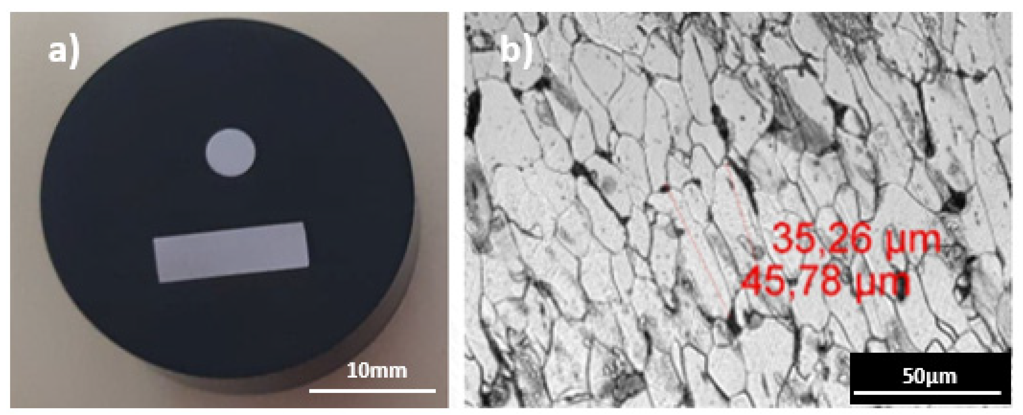
3.2. Coating Characterization

Some of the most relevant parameters of the coatings were analyzed, using the aforementioned sub-samples of the cross and longitudinal sections encapsulated in Bakelite cylinders (Figure 4).
Firstly, the coating thickness was measured by means of an optical microscope. Then, the hardness of the coating was obtained by means of a microhardness testing equipment. For this purpose, the tests were carried out under a 5 mN load and unload model in order not to puncture out of the layer (due to their reduced thickness); the Vickers Hardness (HV) scale was employed and a total of 5 indentations were performed in each sample, taking the average as a representative result.
Then, the rugosity of the five samples was measured; a portable roughness meter was employed for a total of 5 measurements in each sample, taking the average as a representative result. Finally, the composition of each coating was analyzed by means of semi-quantitative SEM microscopy. A pattern line was drawn, covering the entire thickness of the coating, and an average composition was calculated from the spectrum obtained by the apparatus employed.

3.3. Whisker and Hillock Quantification

The main aim of this report is to study the evolution of zinc whisker growth in the different coatings throughout in-service time, with the aim of quantifying the density of whiskers and hillocks. In this regard, the bibliography [2,3] points out the positive influence on ZW development in compressed areas when electroplated or galvanized components are subjected to bending, a common work situation for loaded trays. In order to study this effect, two loading conditions have been considered: samples without any solicitation, samples subjected to compression stresses caused by a flexural solicitation, designed respectively as “R” (as Received) and “F” (Flexural solicitation) for simplicity.
An experimental program was designed consisting of a monthly inspection by means of scanning electron microscopy (SEM) of the surface of the samples in the situations “R” (without efforts) and “F” (subjected to bending). For a SEM observation, all of the samples have a size restriction in order to fit into the examination platform; so, from each of the received meshes, two samples were extracted, as shown in Figure 5, one for the stress-free state (R) and another that was subjected to compression bending using an experimental tool built for this purpose (F).
In order to reproduce the environmental conditions present in data centers, or facilities where cable trays are usually installed, the samples were stored in the microscopy laboratory, where the temperature conditions are kept constant between 20 °C and 22 °C and the presence of electronic equipment, wiring and the magnetic fields generated by them, are similar to those of these facilities. The samples were not manipulated or exposed to air currents, thus reproducing the statics of a real facility.
The first issue encountered was the cylinder shape of the bending samples. In order to have the best view possible of the whiskers, the images were taken from the side and not from the top of the sample, which gives depth to the picture. The only extractable image format from the SEM is a grey scale picture with no information about the height or the position of the elements studied. In order to try to implement an automatic whisker and hillock quantification, simple segmentation tests have been run, and element tracking software has been tried, but with little success and with very noisy and unexploitable results; no automatic counting and recognizance program has been encountered to carry out this task. After checking the bibliography, it was found that all the previous searches on the same subject also used a hand counting system [2].
Finally, for this research, the quantification was semi automatized. For each sample, pictures of a certain marked zone were taken monthly in both stress-free (R) and bending (F) states; the study was performed with a twelve month time lapse. The quantification was based on only four images without any overlaps between them. Reduced images were mandatory as the shape of the sample is cylindrical so the focus cannot be on the entire image; a reduced frame was applied for the two types: 686 × 600 pixels in the case of stress-free (R) samples and 1024 × 400 pixels in the case of bending (F) samples.
The first step was to identify the hillocks on this frame and, in a second stage, the whiskers were enumerated; no size restriction had been applied for the whisker length. Then, the evolution over time of each of the hillocks and whiskers identified was controlled. For each sample, pictures were taken monthly in both F and R states for twelve months; also, a first picture was taken immediately after the sample preparation (month 0), when the cable trays had been stored for around two months after manufacture.
In order to proceed to the control of the hillocks and whiskers over time, the evolution of each of these identified items was followed in each inspection. It should be noted that the pictures taken were covering the exact same area each month with the same conditions and with identical parameters in every test, so the whiskers identified and controlled were the same month after month. Figure 6 and Figure 7 show, respectively, the evolution of a whisker and a hillock over time in a white alkaline electrolyte sample without compressive stresses (as received). In Figure 6, it can be observed how the whisker under study remains constant at a length of around 14 μm, while the whisker density observed in the image does not. In Figure 7, it can be observed how the hillock decreases from 130 to 80 μm over the first five months, going down to around 75 μm during another 4 months; hillock density remains constant over the whole time of study.

4. Coating Characterization Results

4.1. Coating Thickness Analysis

Figure 8 corresponds to microscope observations of the coatings at different magnifications (×100 ×200 and ×500), to identify in each case the relevant measurements.
The white alkaline coating seems to have quite a regular thickness, with the measurements displaying an average thickness of around 14 μm. On examining the coating, sectioned hillocks were observed (×500 image), having a diameter of 30 μm and a height of around 11 μm; these hillocks can be described as having a semi-spherical shape. The yellow trivalent zinc electrolyte (sample 2) also has a steady thickness of around 15 μm; in this case, some sectioned hillocks have also been found, presenting a similar shape description and size as for sample 1.
The acid coating (sample 3) is slightly thicker than the above ones, and reaches around 20 μm; a thin layer (of around 7 μm) can be seen on the external side, which is not part of the coating, but seems rather to be the void created by the thermal retraction of the Bakelite cylinder that had been filed using polishing dusts during this process.
For the hot-dip-galvanized coating (sample 4), the coating is notably ten times thicker than the above ones, and the external surface seems more irregular (×200-magnification image). In this case, no trace of hillocks was found, as the undulations found correspond to the coating irregularities.
Finally, the zinc–nickel coating (sample 5) has an average of 14 μm thickness, similar to the ones observed in all the above samples except the hot-dip-galvanized one. The presence of several cracks at a space from each other can be observed in all the coating (×200 magnification). As this crack damage does not appear in the SEM images used for the whisker study (see Section 5), and has a high hardness of over 350 HV (see Section 4.2), it has been assumed that the cracks are a product of the cutting and polishing steps.

4.2. Coating Hardness

Table 2 gathers the results of the Vickers hardness test on each of the five samples.
Sample 5 seems to have the greatest hardness, a fact that could explain its extreme fragility and the cracks observed with the optical microscope (see Section 4.1); this value is high compared to the other coatings. However, this result looks coherent considering that the sample 5 coating is an alloy of zinc and nickel.
Sample 3, acid electrolyte coating, has the lowest value with an average of around 52 HV. The alkaline electrolyte coatings 1 and 2 have values of around 80 HV and 108 HV, respectively. The hot dip galvanized coating has an intermediate average value of 162 HV.

4.3. Rugosity of the Coatings

Table 3 gathers the results of the superficial rugosity tests on each of the five samples. Samples 3 and 5 have the lowest rugosity values, which matches with the flat and smooth surface observed by SEM techniques (see Section 5). Sample 4 is the one with the most irregular surface, also in agreement with SEM images.

4.4. Chemical Composition

Table 4 gathers the semi-quantitative composition of each of the five coatings. It can be noted that coating 4 (hot-dip-galvanized) is the one that has the highest percentage of Zinc, followed by coating 3 (acid electrolyte) with 85.72 wt%. Coatings 1 and 2 (alkaline white alkaline and yellow trivalent respectively) seem to have an almost identical zinc concentration of around 80 wt%. Concerning coating 5 (zinc-nickel), it is understandable that the zinc concentration is lower, as this is an alloy with approximately 11 wt% of Nickel. In each coating we can also find small percentages of oxygen and carbon, ranging from 1 to 4 wt% and 6 to 16 wt%, respectively.

5. Whisker and Hillock Quantification and Evolution

5.1. First Observations from Preliminary Analysis of the Samples

From a first general analysis of the pictures obtained monthly, preliminary conclusions can be drawn by analyzing Figure 9, Figure 10, Figure 11, Figure 12 and Figure 13. It must be taken into account that at the moment when the study started, the cable trays had been stored for approximately two months after their manufacturing.
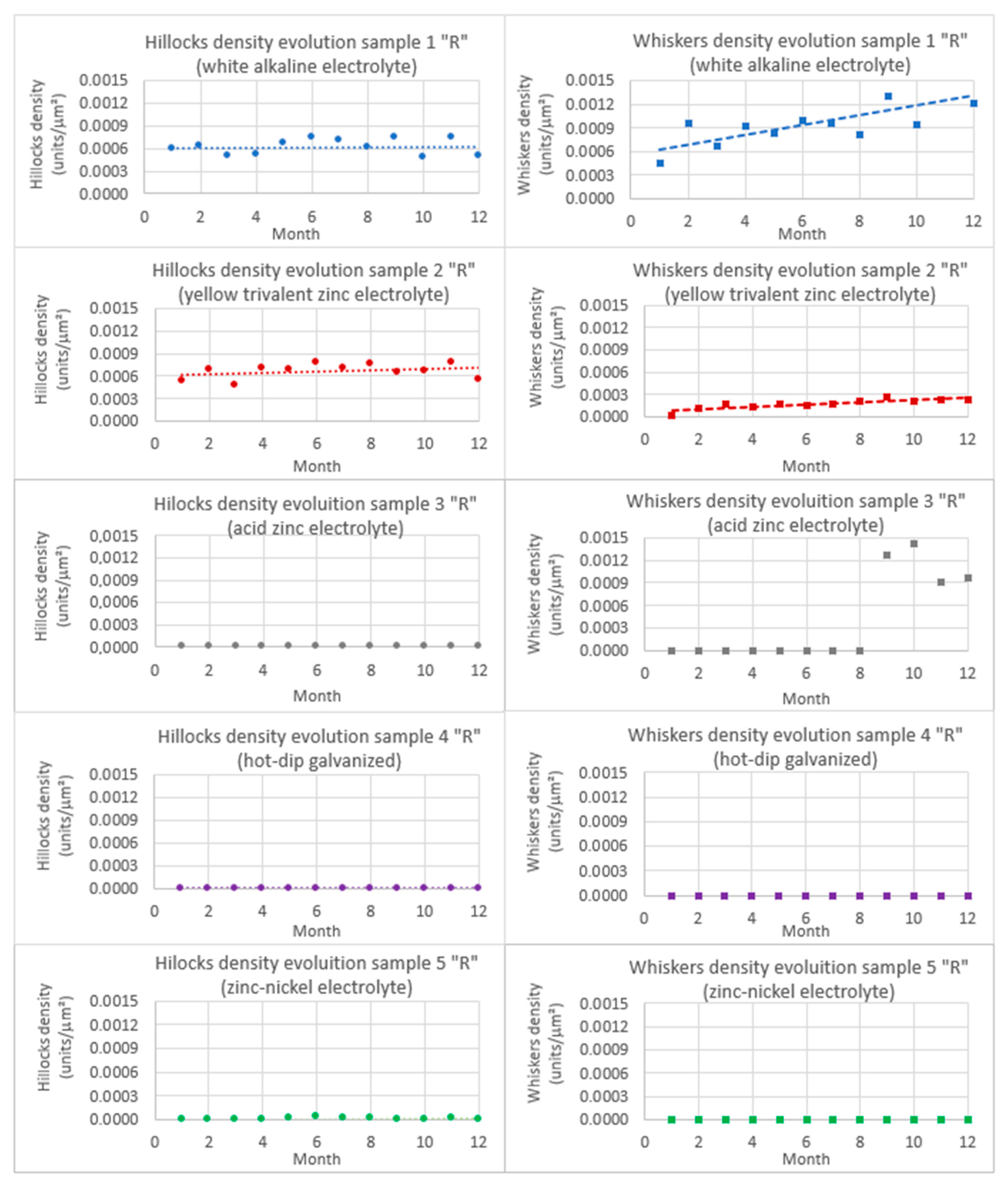
  • As can be appreciated in Figure 9 and Figure 10, in the cases of samples 1 and 2, the white alkaline electrolyte coating and the yellow trivalent zinc electrolyte coating, respectively, a significant growth of whiskers on the surface can be noted from the first months. It was also noted that in the compressed samples (F), the density of whiskers was greater than in the non-compressed ones (R).
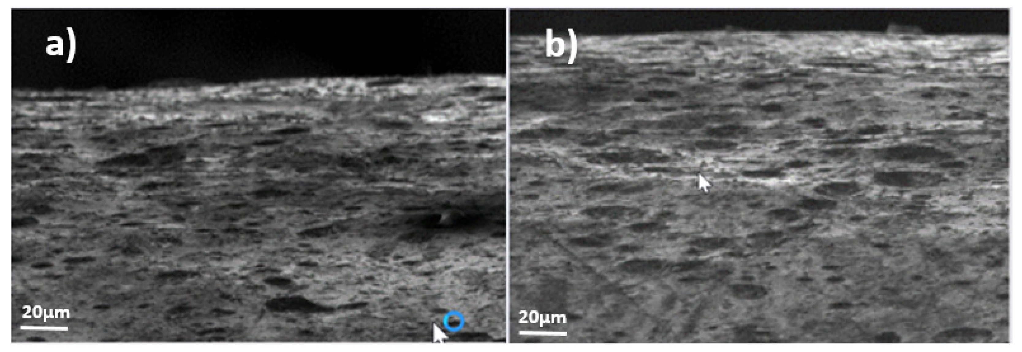
  • As shown in Figure 11, for the 3rd coating, the acid zinc electrolyte coating, no visual change was observed before the 9th month, where the appearance of new elements indentified as zinc whiskers on the surface could be appreciated (highlighted in white or light gray in the photo). No hillocks were found during the study, the whiskers appearing directly.
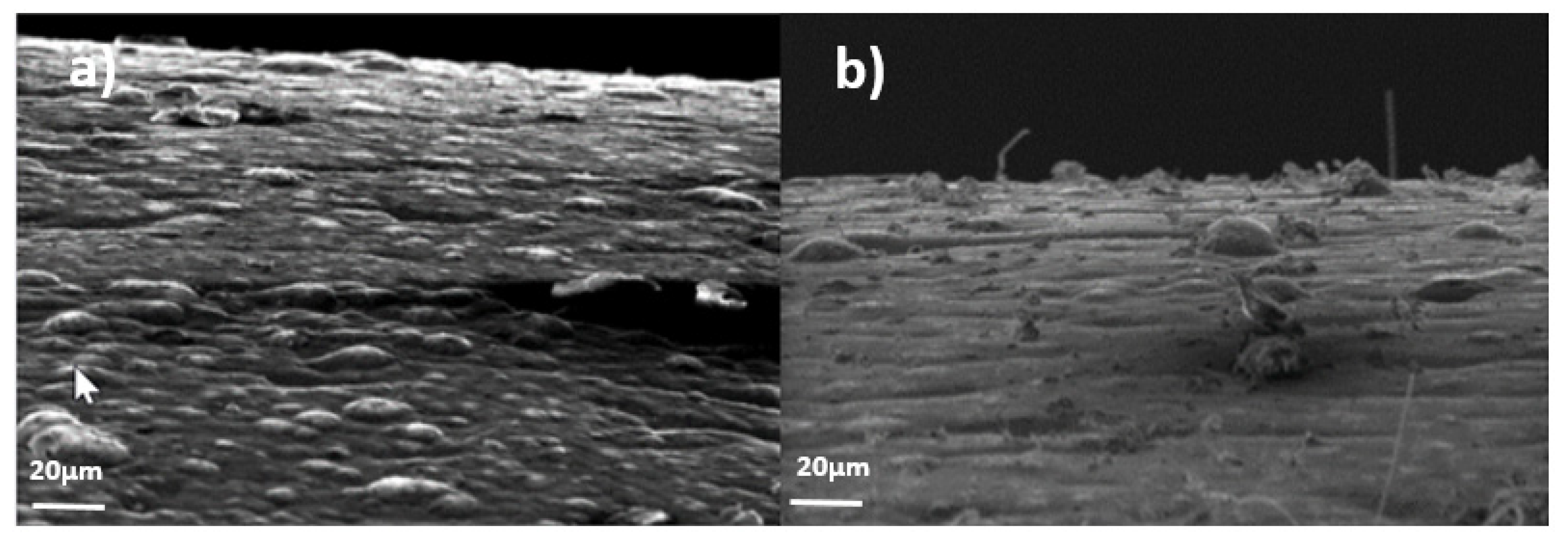
  • In Figure 12, for the hot-dip galvanized coating (sample 4), it can be appreciated that its appearance is different from the rest; a much rougher surface is observed. However, no whiskers were detected during the entire observation period.
  • Figure 13, for sample 5, which corresponds to the zinc-nickel coating, did not present any representative growth of whiskers on the surface during the period studied. The surface of this coating is also smoother, as in the other electrolyte coatings.
This means that the influence of each of the five coatings on whisker and hillock growth is different, even though the substrate material is exactly the same. While coatings 1 and 2 (white alkaline electrolyte coating and yellow trivalent zinc electrolyte coating, respectively) exhibit a surface with numerous hillocks and whiskers from the beginning, samples 4 and 5 (hot-dip galvanizing and zinc-nickel) do not show any evolution and do not present any whiskers on their surface. Finally, sample 3 (acid zinc electrolyte coating) incubates the ZW phenomena for the first 9 months after it appears.

5.2. Quantification of as Received “R” Samples

The following graphs in Figure 14 show the evolution of the hillocks and whiskers in the samples without efforts (R).
Regarding sample 1, the white alkaline electrolyte coating, it can be observed how both graphs show a certain dispersion due to the high degree of uncertainty of the hand counting system. However, it can be noticed that the quantity of hillocks remains relatively constant for the all period considered, whereas the whisker evolution seems to increase in a relatively linear way. It can be noticed that the average density of the hillocks is around 6 × 10⁻⁴ hillocks/μm², while a whisker evolution of between 4 × 10⁻⁴ and 1.6 × 10⁻³ whiskers/μm² was observed.
The trend of sample 2, the yellow trivalent zinc electrolyte coating, is clearer than the previous one, with a relatively constant hillock density during the study period and a visible increase in the whisker density. The uncertainty is also present, in the same order of magnitude as in the previous sample. An average hillock density of 7 × 10⁻⁴ hillocks/μm² and a whisker progression of between 1 × 10⁻⁴ and 2.75 × 10⁻⁴ whiskers/μm² are observed.
If a comparison is made between samples 1 and 2 (white alkaline electrolyte coating and yellow trivalent zinc electrolyte coating, respectively), the hillock density is practically constant and very similar, but the difference in the whisker density is relevant. Tests show that even at the beginning of the study it is possible to detect a one order of magnitude difference in the amount of whiskers, around 4.4 × 10⁻⁴ whiskers/μm² in white alkaline electrolyte (sample 1) and 2.4 × 10⁻⁵ whiskers/μm² in yellow alkaline (sample 2); in the 12th month, a 10-fold difference was observed, reaching densities of 1 × 10⁻³ whiskers/μm² and 2 × 10⁻⁴ whiskers/μm² for samples 1 and 2, respectively.
As shown in the graphs, sample 3 (acid zinc electrolyte coating) did not show any hillocks or whisker progression over the first 8 months. However, traces of a beginning of growth were encountered in the 9th month. As the study covered just 12 months, a clear tendency could not be established; however, the existence of sample 3, the acid zinc electrolyte coating, proves the possibility of a delayed appearance of whiskers without a clear presence of hillocks prior to them at around 10 months of incubation (2 months prior to the sample reception plus the first 8 months of study). According to the graph (Figure 14), it seems that the density is as great as in sample 1, around 1.2 × 10⁻³ whiskers/μm² and constant during months 9th to 12th. However, the length of the whiskers identified is insignificant in comparison with coatings 1 and 2 (Figure 9, Figure 10 and Figure 11). Given this fact, plus the short duration of the evolution study, the density obtained needs to be treated with caution.
As previously mentioned, samples 4 (corresponding to hot-dip galvanized) and 5 (zinc-nickel coating) did not show any significant evolution on the hillocks or whiskers in the as received state (R) during the period of study, so the quantification for these samples gave residual values practically equal to zero.
In Section 2, coating thickness has been coupled with texture, and it was also stated that thinner coatings favor whisker growth [9] by influencing the coating texture [21]. In the five cases studied, the steel substrate was exactly the same, and the thickness of the white alkaline and acid electrolyte coatings were of 14 and 20 μm, respectively, while the hot-dip galvanized was around 100 μm. In view of this, it seems logical that the white alkaline electrolyte presented a lower density of ZW and hillocks than the acid electrolyte. Regarding the hot-dip galvanized coating, whose rugosity was superior to that of the rest of the coatings, the much thicker zinc layer justifies the low presence of whiskers and hillocks.

5.3. Quantification of Compression Stressed Samples by Bending “F”

The following graphs in Figure 15 show the evolution of hillocks and whiskers in the samples with compression stresses applied by bending moment (F).
In sample 1, despite the dispersion, it can be noticed that the quantity of hillocks remains relatively constant during the 12 months of study, around 6 × 10⁻⁴ hillocks/μm²; however, this value was slightly higher in the 1st month of study (approximately 1.2 × 10⁻³ hillocks/μm²). At the same time, the whisker evolution also showed a quasi-constant value after the 2nd month of study around 1.4 × 10⁻³ whiskers/μm²; however, its presence in month 1 was practically inexistent while it rose to 1.8 × 10⁻³ whiskers/μm² in month 2, to go down slightly the aforementioned constant value over the rest of the time. This fact indicates that there could have been a 2 month period when the first hillocks appeared and from them whiskers grew after a certain incubation time, the process stabilizing after the 2nd month.
If samples 1 in “R” and “F” states are compared, it can be noted that, while the hillock density in both cases presents similar values of around 6 × 10⁻⁴ hillocks/μm², the whisker density in the bended samples (R) was higher during the whole study (approximately 1.4 × 10⁻³ whiskers/μm²) although the samples without efforts (R) tended to its value at the end of it (4 × 10⁻⁴ whiskers/μm² at month 1 and 1.6 × 10⁻³ whiskers/μm² at month 12 were observed). This confirms the aforementioned hypothesis from the literature that bending compression stresses, at least in this coating (white alkaline electrolyte), favor the growth of zinc whiskers by accelerating it; on the other hand, no effect of bending stresses have been noticed in relation to the hillocks.
The effects observed on samples 2 (yellow trivalent zinc electrolyte coating) follow the same patterns as the ones described above for samples 1. In this case, quasi-constant values of around 7 × 10⁻⁴ hillocks/μm² and 1.5 × 10⁻³ whiskers/μm² have been found, which compared to 7 × 10⁻⁴ hillocks/μm² and a whisker progression of between 1 × 10⁻⁴ and 2.75 × 10⁻⁴ whiskers/μm², confirms that the aforementioned bending compression stresses favor whisker growth, but not in hillocks. In this case, the incubation period of 2 months observed for coating 1 was not noticed (it may well have taken place in the storage time of the samples prior to the study).
In sample 3 (acid zinc electrolyte coating), no hillocks or whisker progression were noticed during the first 8 months. However, traces of the beginnings of whisker growth were encountered in months 9 to 12, although their density was negligible (5 × 10⁻⁵ whiskers/μm²), so no tendency could be established. In this case, the compression bending stress effect observed in samples 1 (white alkaline electrolyte) and 2 (yellow trivalent zinc electrolyte) that favors whisker growth was not present. In fact, the whisker growth after 8 months was higher in the effort-less samples, but given the presence of this effect at the end of the study, further conclusions should not be made regarding this matter in coating 3.
Sample 4 (hot-dip galvanized) did not show any significant evolution of the hillocks or whiskers under compression bending forces (F) during the period of study, as occurred in the as received state (R), so the quantification for these samples gave residual values practically equal to zero.
However, sample 5 (zinc-nickel coating) showed a constant hillock density of around 1.5 × 10⁻⁵ hillocks/μm² during the whole study from month 3, but no whiskers grew from them at any time, so it can be stated that in this case the compression bending stresses have a slight influence on hillock growth but not on whiskers.
Again for the bended samples, for the 14 and 20 μm thick white alkaline and acid electrolyte coatings, respectively, the results are as stated in the literature: the white alkaline electrolyte presented a lower density of ZW and hillocks than the acid electrolyte, given the fact that thinner coatings favor whisker growth [9] by influencing the coating texture [21]. Additionally, the hot-dip galvanized samples, whose thickness was of 100 micros and with a rugosity superior to the rest of the coatings, the much thicker zinc layer justifies the low presence of whiskers and hillocks.

6. Conclusions and Future Work

In this report, the following five VALDINOX® patented EASYCONNECT system cable trays made out of the same base steel wires but finished in different coatings, which cover a wide range of the commercial offer available at present, have been characterized mainly with respect to their zinc whisker and hillock evolution over 12 months.
  • White alkaline electrolyte coating.
  • Yellow trivalent zinc electrolyte coating.
  • Acid zinc electrolyte coating.
  • Hot-dip galvanizing zinc coating.
  • Zinc-nickel coating.
From the bibliographic review, it was concluded that parameters such as grain size, substrate hardness, microstrain, light and magnetic fields and humidity do not influence the zinc whisker growth (ZW) phenomena. The following variables favor ZW growth: ap-plied external compressive stresses, residual stresses, temperature, corrosion, organic contaminants, thin coatings and thin substrates; in contrast, cyanide electrolytes reduce ZW growth rate by producing less residual stress and chrome inhibits the onset of ZW, but does not prevent them. It was also concluded that elongated Zn grains in the coating tend to raise ZW growth rates more than equiaxial ones, and that stress relaxation might be the driving force of ZW growth.
Secondly, the main parameters of the five aforementioned coatings were characterized in depth. It should be pointed out that:
  • The hot-dip galvanized coating, as already known, is very different from the electrolyte ones (the rest); it is approximately five to seven times thicker and its rugosity is also higher. On the other hand, its composition does not differ much from the rest of the zinc coatings, except for the zinc-nickel one, even though its oxygen content is substantially lower than in the rest.
  • The zinc–nickel coating stands out from the rest for its approximately 11% of zinc substitution by nickel (73% Zn and 11% Ni, instead of around 80% to 85% Zn). The hardness of this coating stands out, it being twice as hard as the hot-dip galvanized one and nearly four times harder than the rest of the coatings, which can make it more brittle.
Finally, a complete study of hillock and whisker density evolution with and without presence of compression stresses, which is one of the most influencing parameters, was completed. After a preliminary analysis, even though the substrate material was exactly the same, different conclusions for the different coatings regarding whisker and hillock growth could be made:
  • After the first 3 months of study, it was clear how the white alkaline electrolyte and the yellow trivalent zinc electrolyte coatings showed a significant growth of ZW and hillocks in the as-received samples as well as in the compressed ones; the whisker density was higher in the compressed samples, but the hillocks were in a similar range in both cases.
  • The acid zinc electrolyte coating did not present any ZW or hillock presence during the first 8 months. After the 9th month, however, small whiskers appeared on the surface, though no presence of hillocks was found during the whole study.
  • The hot-dip galvanized coating presented a much rougher surface than the rest. Nevertheless, no ZW or hillock appearance was observed during the 12 months, either in the as-received or in the compressed samples.
  • The zinc–nickel coating did not present any whisker or hillock growth on the surfaces during the period studied, either in the as-received or in the compressed samples.
In general terms, regarding the four electrolytic coatings which have similar thicknesses, zinc contents (there is a 12% approx. substitution in Zn–Ni coating) and which have been applied on the same substrate, it can be concluded that the white alkaline and yellow trivalent coatings had a quite similar behavior during the 12 months of study, presenting hillocks and zinc whiskers from the beginning and throughout the whole period of study. These two coatings were the most affected ones, the effects on the yellow trivalent coating being slightly worse when compressive stresses are applied.
In comparison with the aforementioned ones, the zinc–nickel coating showed the best behavior, in general terms, with respect to hillock and whisker evolution over the 12 months of study. Nevertheless, although its behavior was qualitatively slightly worse, the acid zinc electrolyte coating (sample 3) also showed good results despite the delayed appearance of whiskers from the month 9.
Finally, in the case of the hot-dip galvanized coating, no presence of zinc whiskers or hillocks was detected during the period of study.
The study carried out covered just 12 months, a far shorter time than the in- service life of cable trays in data centers. A necessary future study might be to extend the study over a longer period of time, to determine whether incubation times of several years might appear on those coatings that did not show any hillock or whisker presence during this study.

Author Contributions

Conceptualization, B.A. and J.S.; methodology, B.A., J.A.Á. and J.S.; software, M.R. and A.I.C.; validation, B.A., G.B. and J.S.; formal analysis, B.A. and S.C.; investigation, B.A., M.R. and A.I.C.; resources, G.B., J.S. and B.A.; data curation, M.R., A.I.C. and B.A.; writing—original draft preparation, B.A., M.R. and J.A.Á.; writing—review and editing, B.A., J.A.Á. and S.C.; supervision, J.A.Á., J.S. and G.B.; project administration, B.A. and J.S.; funding acquisition, B.A. and J.S. All authors have read and agreed to the published version of the manuscript.

Funding

This research was funded by “CONSEJERÍA DE INNOVACIÓN, INDUSTRIA, TURISMO Y COMERCIO of Gobierno de Cantabria”, grant “Cheques de Innovación para el año 2018” and The APC was partially funded by a discount offered by Metals Editorial Office to celebrate the journal’s 10th anniversary and partially by the authors discount vouchers for paper reviews to MDPI.

Institutional Review Board Statement

Not applicable.

Informed Consent Statement

Not applicable.

Data Availability Statement

Data is property of the company VALDINOX Ltd. and the authors of the article. For data request please contact the corresponding author.

Conflicts of Interest

The authors declare no conflict of interest.

References

  1. VALDINOX Website. Available online: http://www.valdinox.com/ES/home (accessed on 11 February 2021).
  2. Cabrera-Anaya, J.M. Growth of Zinc Whiskers. Ph.D. Thesis, Université de Grenoble, Grenoble, France, 2014. [Google Scholar]
  3. Wu, L.; Ashworth, M.A.; Wilcox, G.D. Zinc whisker growth from electroplated finishes–a review. Trans. Inst. Metal Finish. 2015, 93, 66–73. [Google Scholar] [CrossRef] [Green Version]
  4. Zinc Whiskers and Their Role in Data Centre Failures. Available online: http://ritel.co.uk/about-zinc-whiskers.html (accessed on 31 December 2020).
  5. Worldwide Environmental Services (WES). Metallic Whisker Sources. 2004. Available online: www.wes.net (accessed on 31 December 2020).
  6. Lahtinen, R.; Gustafsson, T.E. The Driving Force Behind Whisker Growth, An Investigation on What Triggers This Phenomenon in Hot-Dip Galvanized Zinc Coating, Part 1. Metal Finish. 2005, 103, 25–29. [Google Scholar] [CrossRef]
  7. Lahtinen, R.; Gustafsson, T.E. The Driving Force Behind Whisker Growth, An Investigation on What Triggers This Phenomenon in Hot-Dip Galvanized Zinc Coating, Part 2. Metal Finish. 2005, 103, 33–36. [Google Scholar] [CrossRef]
  8. Wu, L. Zinc Whisker Growth from Electroplated Finishes; Department of Materials Loughborough University: Loughborough, UK, 2015. [Google Scholar]
  9. Compton, K.G.; Mendizza, A.; Arnold, S.M. Filamentary Growths on Metal Surfaceswhiskers. Corrosion 1951, 7, 327–334. [Google Scholar] [CrossRef]
  10. Takemura, T.; Kobayashi, M.; Okutani, M.; Kakoshita, T.; Shimizu, K. Relation Between the Direction of Whiskers Growth and the Crystallographic Texture of Zinc Electroplate. Jpn. J. Appl. Phys. 1986, 1, 1948. [Google Scholar] [CrossRef]
  11. Lindborg, U.; Ramsin, S.; Lind, L.; Revay, L. Microstructure and Metallurgical Properties of Some Zinc Electroplates. Plating 1974, 61, 1111–1116. [Google Scholar]
  12. Etienne, A.; Cadel, E.; Lina, A.; Cretinon, L.; Pareige, P. Micro- and Nanostructure of Zn Whiskers and Their Coating. J. Electr. Mater. 2013, 42, 272–279. [Google Scholar] [CrossRef] [Green Version]
  13. Reynolds, H.L.; Hilty, R. Investigations of Zinc Whiskers Using FIB Technology. In Proceedings of the IPC/JEDEC Lead Free North America Conference, Boston, MA, USA, 2004; Available online: https://www.semanticscholar.org/paper/Investigations-of-Zinc-(Zn)-Whiskers-using-FIB-Reynolds-Hilty/7d4567bb784d9b5786fa89b1f6bec73d46744fcd (accessed on 31 December 2020).
  14. Xu, C.; Zhang, Y.; Fan, C.; Abys, J.A. Understanding Whisker Phenomenon: The Driving Force for Whisker Formation. 2002. Available online: http://thor.inemi.org/webdownload/projects/ese/ChenXuAPEX02-presenta.pdf (accessed on 31 December 2020).
  15. Minakshi, M.; Appadoo, D.; Martin, D.E. The Anodic Behavior of Planar and Porous Zinc Electrodes in Alkaline Electrolyte. Electrochem. Solid-State Lett. 2010, 13, A77. [Google Scholar] [CrossRef]
  16. Minakshi, M.; Mitchell, D.R.G.; Prince, K. Incorporation of TiB2 additive into MnO2 cathode and its influence on rechargeability in an aqueous battery system. Solid State Ion. 2008, 179, 355–361. [Google Scholar] [CrossRef]
  17. Minakshi, M.; Ionescu, M. Anodic behavior of zinc in Zn-MnO2 battery using ERDA technique. Int. J. Hydrog. Energy 2010, 35, 7618–7622. [Google Scholar] [CrossRef]
  18. Baated, A.; Kim, K.; Suganuma, K. Whisker Growth from an Electroplated Zinc Coating. J. Mater. Res. 2010, 25, 2175–2182. [Google Scholar] [CrossRef]
  19. Frank, F.C. On Tin Whiskers. Philos. Mag. 1953, XLIV, 854–860. [Google Scholar] [CrossRef]
  20. Eshelby, J.D. A Tentative Theory of Metallic Whisker Growth. Phys. Rev. 1953, 91, 755–756. [Google Scholar] [CrossRef]
  21. Lindborg, U. Observations on the Growth of Whisker Crystals from Zinc Electroplate. Metall. Trans. A 1975, 6, 1581–1586. [Google Scholar] [CrossRef]
  22. Lindborg, U. A model for the spontaneous growth of zinc, cadmium, and tin whiskers. Acta Metall. 1976, 24, 181–186. [Google Scholar] [CrossRef]
  23. Philibert, J. Diffusion et Transport de Matière dans les Solides; Les Editions de Physique: Paris, France, 1985. [Google Scholar]
  24. Ellis, W.C.; Gibbons, D.F.; Treuting, R.C. Growth of Metal Whiskers from the Solid, Growth and Perfection of Crystals; Doremus, R.H., Roberts, B.W., Turnbull, D., Eds.; John Wiley & Sons: New York, NY, USA, 1958; pp. 102–120. [Google Scholar]
  25. Glazunova, V.K.; Kudryavtsev, N.T. An Investigation of the Conditions of Spontaneous Growth of Filiform Crystals on Electrolytic Coatings. Russ. J. Appl. Chem. (Zhurnal Prikladnoi Khimii) 1963, 36, 543–550. [Google Scholar]
  26. Kakeshita, T.; Shimizu, K.; Kawanaka, R.; Hasegawa, T. Grain Size Effect on Electroplated Tin Coatings on Whisker Growth. J. Mater. Sci. 1982, 17, 2560–2566. [Google Scholar] [CrossRef]
  27. Le-Bret, B.; Norton, M.G. Electron Microscopy Study of Tin Whisker Growth. J. Mater. Res. 2003, 13, 585–593. [Google Scholar] [CrossRef]
  28. Boguslavsky, I.; Bush, P. Recrystallization Principles Applied to Whisker Growth in Tin. In Proceedings of the APEX Conference, Anaheim, CA, USA, 31 March–2 April 2003. [Google Scholar]
  29. Smetana, J. The end Game. IEEE Trans. Electron. Packag. Manuf. 2007, 30, 11–22. [Google Scholar] [CrossRef]
  30. Vianco, P.T.; Rejent, J.A. Dynamic Recrystallization (DRX) as the Mechanism for Sn Whisker. J. Electron. Mater. 2009, 38, 1815–1825. [Google Scholar] [CrossRef] [Green Version]
  31. Etienne, A.; Cadel, E.; Lina, A.; Cretinon, L.; Pareige, P. Crystallographic Characterization of an Electroplated Zinc Coating Prone to Whiskers. IEEE Trans. Compon. Packag. Manuf. Technol. 2012, 2, 1928–1932. [Google Scholar] [CrossRef]
  32. Sugiarto, H.; Christie, I.R.; Richards, B.P. Studies of Zinc Whiskers Formation and Growth from Bright Zinc Electrodeposits. Trans. Inst. Metal Finish. 1984, 62, 92–97. [Google Scholar] [CrossRef]
  33. Nagai, T.; Natori, K.; Furasama, T. Rate of Short-Circuit Caused by Whiskers Growth on Zn Electroplated Steels in Electronic Appliance. J. Jpn. Inst. Metals 1989, 53, 303–307. [Google Scholar] [CrossRef] [Green Version]
  34. UNE-EN 12329:2001. Corrosion Protection of Metals. Electrodeposited Coatings of Zinc with Supplementary Treatment on Iron or Steel; CTN 112; BSI: London, UK, 2001. [Google Scholar]
Figure 1. Differences in ZW growth in zinc coated surfaces after 10 months in service. It can be observed how white zinc alkaline coating (left) developed substantially more ZW than hot dip galvanized coating (right), where its presence is null.
Metals 11 00325 g001
Figure 2. (a) Nodular whiskers. (b) Rectilinear whiskers and hillocks. (c) Whiskers with abrupt changes of direction. (d) regular shape of hillocks.
Metals 11 00325 g002
Figure 3. Fe-Zn phase diagram.
Metals 11 00325 g003
Figure 4. (a) Wire longitudinal and cross section encapsulated in Bakelite and polished. (b) Microstructure and grain size of the samples studied. Remark: Decimal separator in these images is “,” instead of “.”.
Metals 11 00325 g004
Figure 5. Example of some of the samples prepared for introduction into the SEM. (a) R samples; (b) F samples.
Metals 11 00325 g005
Figure 6. Example of evolution of a whisker in a white alkaline electrolyte sample without compressive stresses over time.
Metals 11 00325 g006
Figure 7. Example of evolution of a hillock in a white alkaline electrolyte sample without compressive stresses over time.
Metals 11 00325 g007
Figure 8. Thickness analysis by optical microscope of the different samples: white alkaline coating (Sample 1), yellow trivalent zinc electrolyte (Sample 2), acid zinc electrolyte (Sample 3), hot-dip galvanizing (Sample 4) and zinc-nickel (Sample 5). Remark: Decimal separator in these images is “,” instead of “.”.
Metals 11 00325 g008
Figure 9. Example of surface evolution in white alkaline electrolyte (sample 1) under compressive stresses (F); (a) month 1, (b) month 3.
Metals 11 00325 g009
Figure 10. Example of surface evolution in yellow trivalent zinc electrolyte (sample 2) without stresses (R); (a) month 1, (b) month 3.
Metals 11 00325 g010
Figure 11. Example of surface evolution in acid zinc electrolyte coating (sample 3) without stresses (R); (a) month 1, (b) month 9.
Metals 11 00325 g011
Figure 12. Example of surface evolution in hot-dip galvanizing zinc coating (sample 4) under compressive stresses (F); (a) month 1, (b) month 12.
Metals 11 00325 g012
Figure 13. Example of surface evolution in sample 5 under compressive stresses (F); (a) month 1, (b) month 8.
Metals 11 00325 g013
Figure 14. Evolution of hillocks and whiskers in as received “R” samples.
Metals 11 00325 g014
Figure 15. Evolution of hillocks and whiskers in compression stressed samples by bending “F”.
Metals 11 00325 g015
Table 1. Summary of influence of parameters on whiskers growth.
Influencing Parameters
ParameterInfluence
Coating thicknessThe thinner coating favors whisker growth [9] by influencing the coating texture [21] and the residual stress in thin (<5 µm) coatings [32].
Substrate thicknessThe thinner substrate favors whisker growth by influencing the coating texture [21].
Electroplating electrolyteCyanide electrolytes produce less residual stress [11], and therefore a lower whisker growth rate.
Organic contaminants (including brighteners)Favors whisker growth [9] by increasing compressive localized stress in electroplated metals [32].
ChromeInhibits the onset of whiskers but does not avoid them [32].
Microstructure of the Zn coatingElongated grains tend to have larger whisker growth rates than specimens with equiaxed columnar grains [31].
TexturePlanes {11-20} and {10-1-1} favor whisker growth [10,21].
TemperatureFavors whisker length and density [9] and growth rate [21].
CorrosionTends to aggress the chromium passive layer, that protects the zinc coating, which eases the whiskers to pop out [6,7].
Residual stress in the coatingsFavors whisker growth rate [11,21] and decreases incubation time [33].
Applied external
compressive stress
Compressive applied stress favors growth more than tensile applied external stress [14].
Stress relaxationMight possibly be the driving force of zinc whisker growth [1,23].
Non-Influencing Parameters
ParameterComments
Grain sizeNo clear influence observed [21].
HardnessNo influence observed [21].
MicrostrainNo influence observed [21].
Light and electromagnetic fieldNo influence observed [6,7,9].
HumidityNo influence observed [9].
Table 2. Vickers hardness.
SampleInd. 1 (HV)Ind. 2 (HV)Ind. 3 (HV)Ind. 4 (HV)Ind. 5 (HV)Average Hardness (HV)
White alkaline (1)87.484.483.594.650.780.2
Yellow trivalent (2)102.4130.2113.5102.593.7108.5
Acid zinc electrolyte (3)53.753.552.254.348.652.5
Hot-dip galvanizing (4)148.5142.3144.5206.1172.2162.7
Zinc-nickel (5)376.1326.5383.3303.9390.2356.0
Table 3. Superficial rugosity of the coatings.
SampleRug. 1 (μm)Rug. 2 (μm)Rug. 3 (μm)Rug. 4 (μm)Rug. 5 (μm)Average Rugosity (μm)
White alkaline (1)0.380.390.260.310.410.30
Yellow trivalent (2)0.390.310.380.410.310.28
Acid zinc electrolyte (3)0.270.210.300.320.300.22
Hot-dip galvanizing (4)0.470.550.620.490.670.44
Zinc-nickel (5)0.310.220.250.320.220.21
Table 4. Chemical composition of the coatings.
SampleZn (wt%)Ni (wt%)C (wt%)O (wt%)Total (wt%)
White alkaline (1)80.96-15.273.77100
Yellow trivalent (2)79.86-15.874.27100
Acid zinc electrolyte (3)85.72-11.362.92100
Hot-dip galvanizing (4)92.26-6.631.11100
Zinc-nickel (5)73.7311.7410.613.92100
Publisher’s Note: MDPI stays neutral with regard to jurisdictional claims in published maps and institutional affiliations.

