Article

Reduction of Die Wear and Structural Defects of Railway Screw Spike Heads Estimated by FEM

by
Jackeline Alcázar
1,
Germán Abate
1,2,
Nazareno Antunez
1,2,
Alejandro Simoncelli
1,2,
Antonio J. Sánchez Egea
3,
Daniel Martinez Krahmer
1,2 and
Norberto López de Lacalle
4,*
1
Faculty of Engineering, Universidad Nacional de Lomas de Zamora, Juan XXIII y Camino de Cintura, Buenos Aires 1832, Argentina
2
Center for Research and Development in Mechanics, National Institute of Industrial Technology (INTI), Avenida General Paz 5445, Buenos Aires 1650, Argentina
3
Department of Mechanical Engineering (EEBE), Universitat Politècnica de Catalunya, Av. D’Eduard Maristany, 16, 08019 Barcelona, Spain
4
Department of Mechanical Engineering, University of the Basque Country, Escuela Superior de Ingenieros Alameda de Urquijo s/n., 48013 Bilbao, Spain
*
Author to whom correspondence should be addressed.
Metals 2021, 11(11), 1834; https://doi.org/10.3390/met11111834
Submission received: 26 September 2021 / Revised: 9 November 2021 / Accepted: 12 November 2021 / Published: 15 November 2021

Abstract

:
Railway spike screws are manufactured by hot forging on a massive scale, due to each kilometer of railway track needing 8600 spike screws. These components have a low market value, so the head must be formed in a single die stroke. The service life of the dies is directly related to the amount of energy required to form a single screw. The existing standard for spike screws specifies only the required tolerances for the head dimensions, particularly the angle of the hub faces and the radius of agreement of the hub with the cap. Both geometrical variables of the head and process conditions (as-received material diameter and flash thickness) are critical parameters in spike production. This work focuses on minimizing the energy required for forming the head of a railway spike screw by computational simulation. The variables with the highest degree of incidence on the energy, forging load, and filling of the die are ordered statistically. The results show that flash thickness is the variable with the most significant influence on forming energy and forming load, as well as on die filling. Specifically, the minimum forming energy was obtained for combining of a hub wall angle of 1.3° an as-received material diameter of 23.54 mm and a flash thickness of 2.25 mm. Flash thickness generates a lack of filling at the top vertices of the hub, although this defect does not affect the functionality of the part or its serviceability. Finally, the wear is mainly concentrated on the die splice radii, where the highest contact pressure is concentrated according to the computational simulation results.

1. Introduction

The railway transport system is one of the main transport systems used worldwide, and railways transport both people and cargo. Its importance is due to its strong influence on many countries’ social, economic, and industrial development [1]. Many components of the railway system require forging, such as railway wheels, axles, crankshafts, large and small connecting rods, disk brakes, chassis components, connection couplings, and sleeper screws [2]. These parts require superior strength and toughness [3], given their demanding service conditions. A critical component of the railway track is spike screws. These parts are mass-produced because 8600 of them are used for each kilometer of track [4]. These components are manufactured by forging, which involves a press [5], dies [6], and a lubrication system [7].
The spike screws connect the rails to the sleepers and, together with the pads, elastic clips and guide plates constitute the fastening system [8]. The spike screw links the parts of the track and has a safety aspect since the failure of these parts in service conditions can cause accidents. These failures, caused mainly by the spike screw fracture, can result from over-tightening, under-tightening, or fatigue [9]. Faria et al. [9] studied the spike screws commonly used by the Brazilian railway sector due to their recurrent failures of these parts during service conditions. A computational simulation helps to propose screw spikes geometries modifications that can result in improved theoretical fatigue resistance. Moreover, Moreira et al. [4] deployed experimental tests and computational simulation intending to improve the screw behavior in fatigue conditions, proposing changes in the material and the thermal treatments of the spike screws. The spike screws are manufactured in two steps, firstly by heating one part of the blank to forge the head of the screw. Then, the other part is heated to create the thread by rolling using three dies. It is a standard procedure used by the forging industry in Argentina [10]. Some tests have been done by heating both sides of the blank and forming the two sides of spike screws simultaneously, thus increasing productivity. For example, Gontarz et al. [11] developed a mechanical press that forges the head at each end of the blank (double configuration) and then synchronizes this equipment with a linear wedge forging machine that threads the body of both screws. In the end, that machine could manufacture two pieces at a time. Regarding the internal defects produced by the wedge forging machine, Van Hai and Hong Hue [12] studied a hot tapping process of AISI 1045 spike screws because their internal defects can significantly reduce their fatigue strength. They were able to reproduce the defects as mentioned above by computational simulation, a situation that enables them to carry out a future improvement on the design of mechanical testing of these components.
The energy consumption to form this kind of component directly impacts die wear [13]. It is one of the reasons why the blockers are used in forging processes [14,15]. However, blockers are not always possible to apply due to the low market price of these parts. Due to these limitations, different manufacturing options must be sought, like the one suggested by Hu et al. [16]. They proposed a multi-objective optimization approach on A309 aluminum alloy through the design of experiments, simulation and hydraulic press forming. They found that by combining the operational parameters, the lifespan of the dies could be increased by 23.5% compared to the original process condition. Additionally, replacing the forging dies significantly impacts the process costs, which can reach up to 30% [17]. In particular, wear is responsible for 70% of die failures during service conditions [18]. Many studies have focused on reducing the friction and wear conditions to increase the lifespan of the die. For example, Behrens et al. [19] studied the relationship between surface topography and wear. Accordingly, they fabricated a series of similar dies, whose final surfaces were obtained by turning, milling, and blasting. After forming 500 forged gearwheel specimens by each method, they determined that the slightest geometrical deviation was achieved with the milled die, while the most significant deviation occurred in the turned die [19]. Likewise, Krawczyk et al. [20] studied surface thermal softening in forging dies. They measured surface temperatures in the order of 600 °C, which produced a softening up to a depth of 0.3 mm. The thermal impact led to a decrease in the die hardness, which causes accelerated wear due to abrasion and plastic deformation.
The German company Hirschvogel [21], which specializes in the forging of parts for the automotive sector, details the reasons why it is very important to simulate forging processes: reducing the time of research and development, early detection of failure zones, a decrease of the cutting weight, a better understanding of the process, among others. In this way, the general procedure is to design the forging parts in CAD programs and then study the mechanical behavior with finite element simulation programs. The objective is to calibrate the process to reduce design failures or defects in the material due to excessive deformations. Once manufactured, the component’s mechanical properties are studied and its surface properties are analyzed by non-destructive testing to find cracks, folds, or other defects. In this sense, Prabhu et al. [22] analyzed forged parts for the aeronautical sector by combining simulation and experimental techniques to carry out its development. After producing parts with the adjusted process, they did not present surface defects and their mechanical properties were 10% higher than those specified in the technical drawing. Additionally, Behrens and coworkers [23] developed a finite element model describing scale behavior to be incorporated into commercial software used to simulate these processes, given the influence of scale formation on friction and material flow in forging die cavities.
Generally, the validation of the mechanical behavior of components in railway lines, such as the spike screws, requires compliance with specific regulations. The legislation establishes the nominal dimensions and tolerances for the hub angle, hub to cap radius, and the starting material’s diameter. The aim of this research is to deepen the head forming process by hot-forging with experiments to determine the geometric combination that generates the lowest energy and correlate the contact pressures obtained by computational simulation with higher wear areas at the head of the spike screws measured with a 3D scan. Therefore, this work’s industrial interest is optimizing the energy to form the head of a spike screw, which is a product of low market value due to its mass production requirement. In this sense, it is possible to produce safe rail fasteners that comply with current regulations and can be formed with a process that reduces production costs, increases the life of the dies, and reduces energy consumption.

2. Materials and Methods

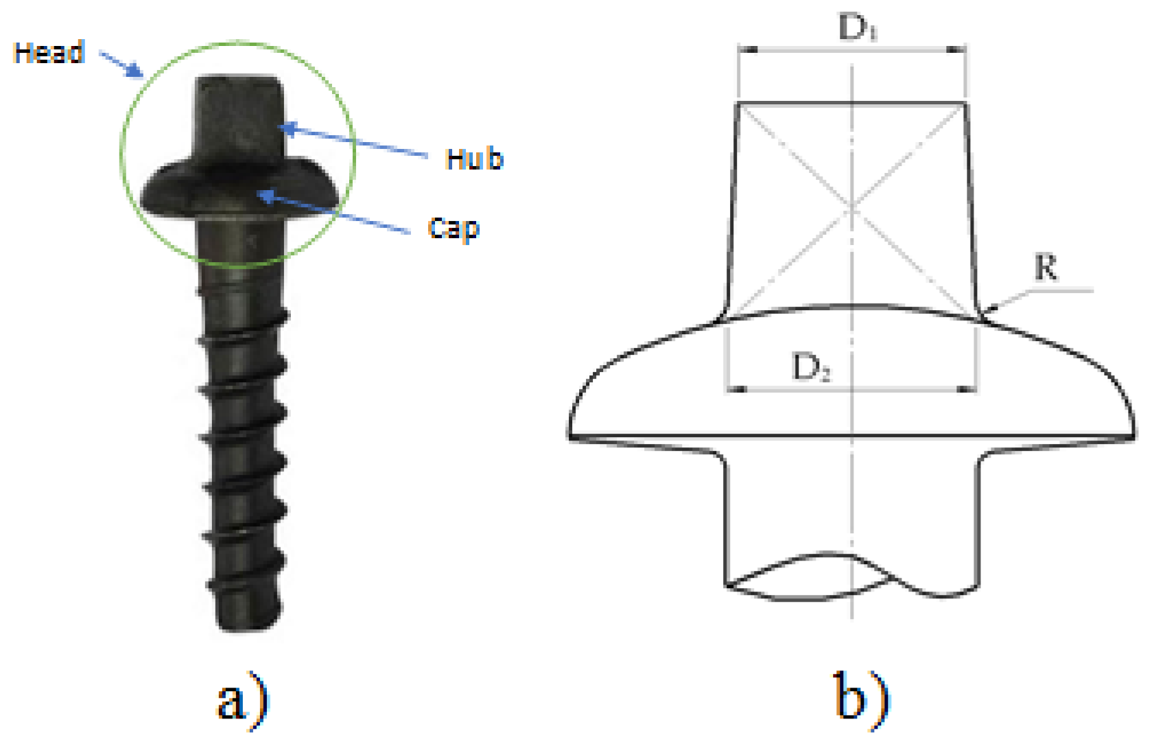
2.1. Dimension and Tolerances of the Screw Spike

This work aims to analyze the influence of the tolerances present in the IRAM-FAT L 7 012 Standard after hot forging the head of the spike screws used for fastening the railroad rails. This work focuses on analyzing the forming process of the head (Figure 1a). This part can be divided into two parts: hub and cap. The standardized measurements of these parts of the head and their respective tolerances are shown in Figure 1b, extracted from the IRAM-FAT L 7 012 Standard.
The influence of the hub wall angle and the hub to cap radius was analyzed. The hub wall angle comes from the dimensions of the base D2 and the top face D1. Table 1 shows the minimum and maximum values corresponding to both variables, D1 and D2 and the hub to cap radius R.
Combining the two hub angles and the two hub and cap joint radii, four die geometries of the screw head can be obtained, as shown in Figure 2. These combinations required a dimensional increase of 1.4% of their cavities due to steel shrinkage [24]. The die for the bottom was the same in all cases.
Regarding the diameter of the as-received material, the manufacturing tolerances published by AINDAR for hot-rolled SAE 1030 steel bars with a nominal diameter of 23.6 mm, whose tolerance is +/−0.26 mm, were used. The nominal size of these bars is the one used by Argentine companies to make railroad lag bolts, because it fits the threaded sector of this product. The flash thickness was taken into two different values, 1.50 mm and 2.25 mm, resulting from the specialized literature analyzed as a function of the weight of the piece. Additionally, the flash gap of the die considered for all simulations was 6.3 mm [24]. Since the four resulting dies present different volumes, in order to carry out a comparative analysis, a burr percentage of 17% was established for all cases with a flash thickness of 1.50 mm. Then, a total head height of 31 mm was set (minimum height according to the manufacturing drawing) so that when using a 2.25 mm flash, the head would not be out of tolerance.

2.2. Material of the Screw Spike

Table 2 shows the average chemical composition by weight of the samples analyzed. This chemical composition is compatible with an AISI 1030 steel and is in the mid-range of carbon steels used in the manufacture of railway screws [4,9,12]. Table 3 shows the mechanical properties of an SAE 1030 steel, which is similar to the chemical composition found in screw spikes.

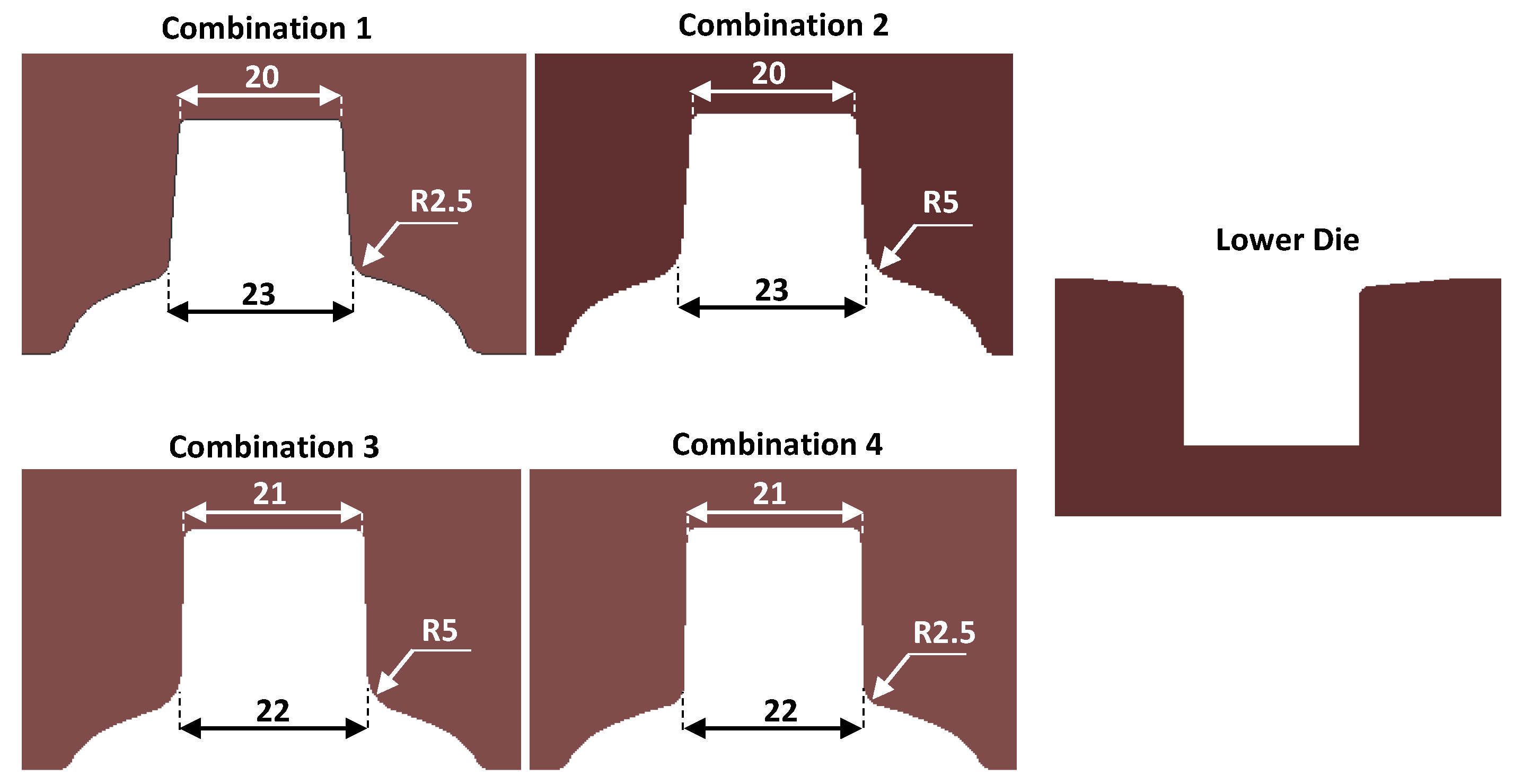
2.3. DOE of the FEM Analysis

A factorial Design of Experiments (DOE) was carried out, resulting from eight computational simulations of the head forming process, which arise from combining the four die geometries with two diameters of the as-received material. Table 4 shows the sixteen variants computed when considering two flash thicknesses.
The simulations were carried out using Simufact-Forming (version 15, Hexagon, Hamburg, Germany) to establish the forging load and the forging energy and verify the matrix’s filling for each combination. Before the simulation, a mesh validation process was performed. The 3D model was used on ¼ of the geometry, using finite volumes with first order and high order mesh quality, with triangular surface mesh sizes elements [26] of 0.7 mm, 1 mm, and 1.8 mm. Five simulations were carried out to study the mesh to find the minimum mesh size that would solve the model in a time no longer than 20 h (stop criterion). Firstly, the whole geometry of the component was considered. In the end, using a quarter of the geometry was enough due to the symmetry of the product. A balance between processing time and accuracy of the results was found with a high order mesh quality and size of 1 mm with a total of 11,176 elements. Table 5 shows the sequence of simulations carried out to balance the quality of results and processing time.
The mechanical press corresponds to a 630 t of capacity with a rod length of 1000 mm, a crankshaft radius of 175 mm, and a stroke frequency of 30 rpm. The material temperature was 1150 °C and the shear friction coefficient was set as 0.4 [18]. These values come from the library of the software for medium carbon steel–steel interaction during hot working. To determine the type of steel to be used during the simulations, chemical analyses were carried out by spark optical emission spectroscopy (OES-spark spectrometer model Q4 Tasman, Bruker, Buenos Aires, Argetina) on samples of spike screws available at the Machining and Forming Processes laboratory of INTI-Mecánica (Buenos Aires, Argentina). During the simulations, in some combinations, the formation of folds occurred. A series of penetrant ink tests were carried out to verify if these folds were found in some of the available samples of spike screws. According to IRAM NM ISO 1972-ASTM E 165, the method was applied using the visible water technique. The final cleaning of the samples was done each time in two stages: washing with solvent and brushing and then drying with a hot air projector. The drying temperature was below 70 °C and a Magnaflux penetrant liquid type SKL-WP with a penetration time of 15 min was used, while the excess liquid was removed by spraying. The developer used was wet non-aqueous SKC-S2.
Two spike screws were scanned, one manufactured from a worn matrix and the other without apparent wear marks, using a structured light 3D scanner (HP, Barcelona, Spain). Subsequently, a study was carried out to determine the measurement deviation with respect to the CAD design using GOM Inspect software (Zeiss, Buenos Aires, Argentina). The results obtained from the computational simulations were evaluated applying the ANOVA statistical tool using Minitab (version 15, Addlink, Madrid, Spain) Box and Pareto plots were utilized to determine the relative importance of each factor and the affected responses and extract the corresponding values of the p-values.

3. Results

The computational simulations for the different geometrical-dimensional combinations and process variables used for head forming are performed. The forming energy, forming loads and contact pressures, the matrix filling, and the appearance of defects (folds) play a crucial role in the screw spike production. Penetrant inks verified the appearance of defects at the surface and the worn areas were evaluated by 3D scanning and validated with the desired CAD part.

3.1. Computational Simulations

Using a 2.25 mm thick burr channel resulted in a lack of filling at the hub vertices in all cases. Figure 3 shows the simulation of that lack of proper filling at the corner of the head of the spike. All simulations used 1.50 mm burr channel thickness showed complete filling of the forming die.
Figure 4 and Figure 5 show the corresponding box plots for load and energy results, segregated by head angle, hub to cap radius, flash thickness, and starting material diameter, respectively. The forming energy and forming load as a function of head angle and hub to cap radius show no significant differences. Additionally, the combination of energy as a function of head angle presents a slight difference in the average of about 9.2%.
Additionally, the statistical analysis of the combination of forming energy and forming load regarding flash thickness shows very significant differences. In particular, as thicker the flash is used, the lower the load and energy required to form the head. Moreover, the diameter of the as-received material presents a lower impact in the process, although it is denoted that as the diameter increases, both load and energy increase. An ANOVA analysis was performed to evaluate more precisely the influence of each parameter on the load and energy values using the p-value with a 0.05 level of confidence. The results of the ANOVA are listed in Table 6.
The ANOVA exhibits that both the flash thickness and the as-received material diameter have a significant influence on the load and energy values and the hub angle that influences the forming energy. On the contrary, the hub to cap radius does not influence the response variables. To determine the order of influence, Figure 6 shows the Pareto diagrams for force and energy.
The Pareto diagrams results indicate that the forming load shows the following influence: flash thickness followed by the as-received material diameter. While the forming energy presents the following order of influence: flash thickness, the as-received material diameter and, also, hub-to-cap radius. Note that when using the largest as-received material diameter, i.e., 24.06 mm, folds appeared during the plastic forming simulation (this was a finding that we had not visualized on the screw spikes samples). Figure 7 shows how these folds are created during the forming process.
Several samples of screws spikes were analyzed with penetrant inks to validate the computational simulations. Figure 8 demonstrates the result of the penetrant inks showing the circular-shaped fold on the cap of the screw.
In Figure 9, it is shown in detail the progress of the contact pressure distribution in the different phases of the forming process. At the step of the head forming, it can be seen that the outer diameter of the material first makes contact with the sides of the tooling cavity. The highest contact pressure is found at the radius of agreement between the cap and the head of the screw spike. The maximum contact pressures were found to be in the order of 884 MPa, while the yield stress of a quenched and tempered AISI H13 steel at 45 HRC was 1280 MPa [26].

3.2. Screw Spike Surface Scanning

The surfaces were scanned to determine the geometric deviations and validate the results of the simulations. Accordingly, Figure 10a exhibits the geometrical deviations of the head of a screw spike formed in an unworn matrix concerning the CAD with the minimum dimensional tolerances. Figure 10b shows the geometrical deviations of the head of a screw spike formed in a worn matrix with respect to the CAD with the minimum dimensional tolerances. Figure 10c compares the deviations between the two previous scanned samples (Figure 10a,b). Finally, Figure 10d corresponds to the worn actual cavity forming the head of a screw spike.
In the screw spike, the wear zones are found in the central part of the sidewalls of the hub and the hub to cap radius of the screw spike (see Figure 10b). This region is where the material first makes contact with the die cavity. Additionally, it is where the highest contact pressures occur during forming, according to the results obtained from the finite volume simulation. The contact pressures, associated with the magnitude of the load and forming energy, inversely depend on the flash dimensions (thickness and length) [27]. In particular, for lower flash thickness, higher plastic strain is determined in the simulation and, therefore, higher forming energy per cycle is assessed; consequently, higher wear of the die is expected. Figure 11 shows the maximum contact pressure regarding the flash thickness and segmented by wear zones (radius and hub face).
Since the deviations of the worn zones are negative, the plastic deformation of the die hub is reducing its size, as shown in Figure 10d. Other aspects of railway tracks manufacturing are related to hole and drilling quality, similar to other cases and applications, so in further research the hole quality will be also investigated [28].

4. Conclusions

This work focuses on minimizing the energy required for metal forming the head of a railway spike screw by computational simulation. The results show the following main conclusions:
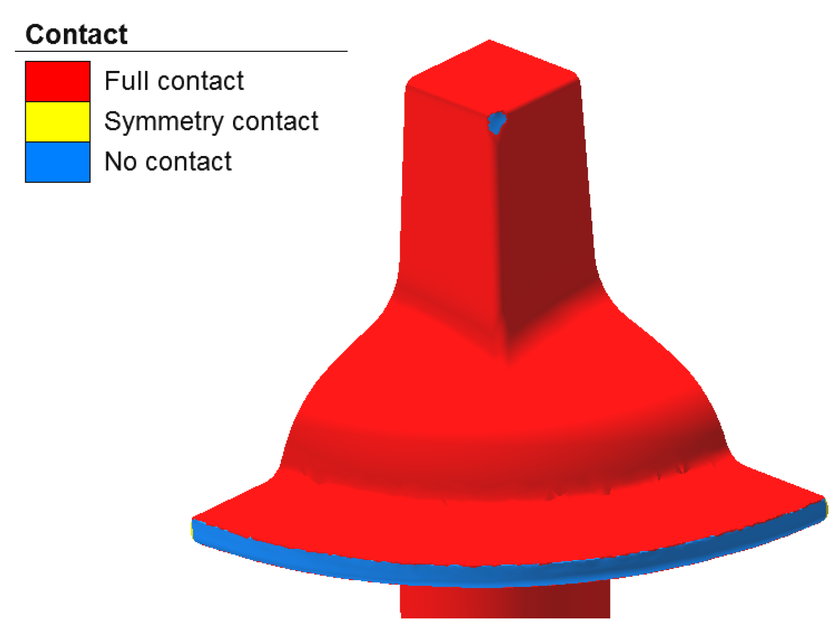
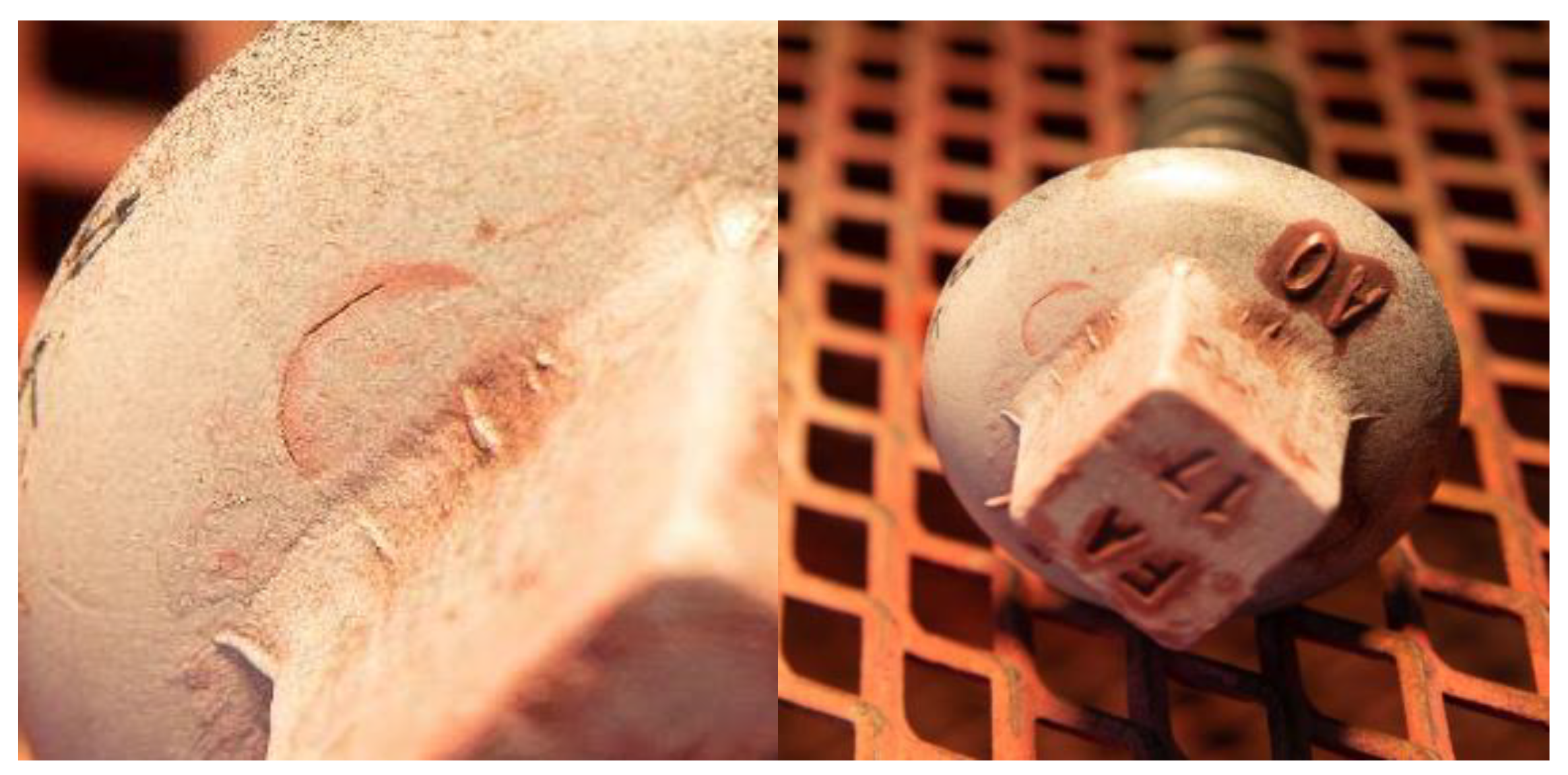
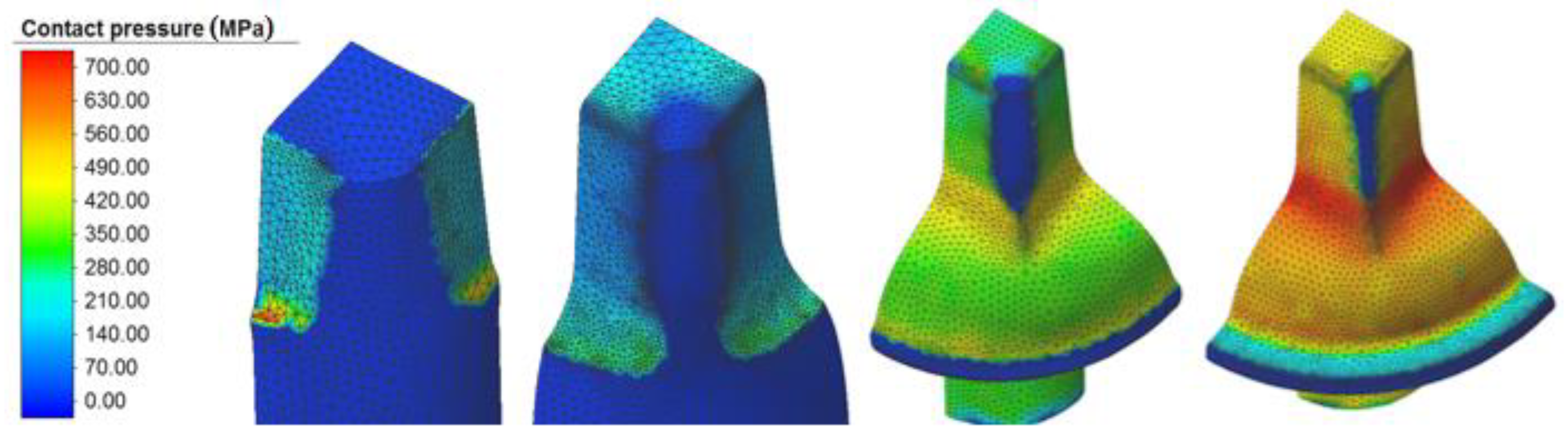
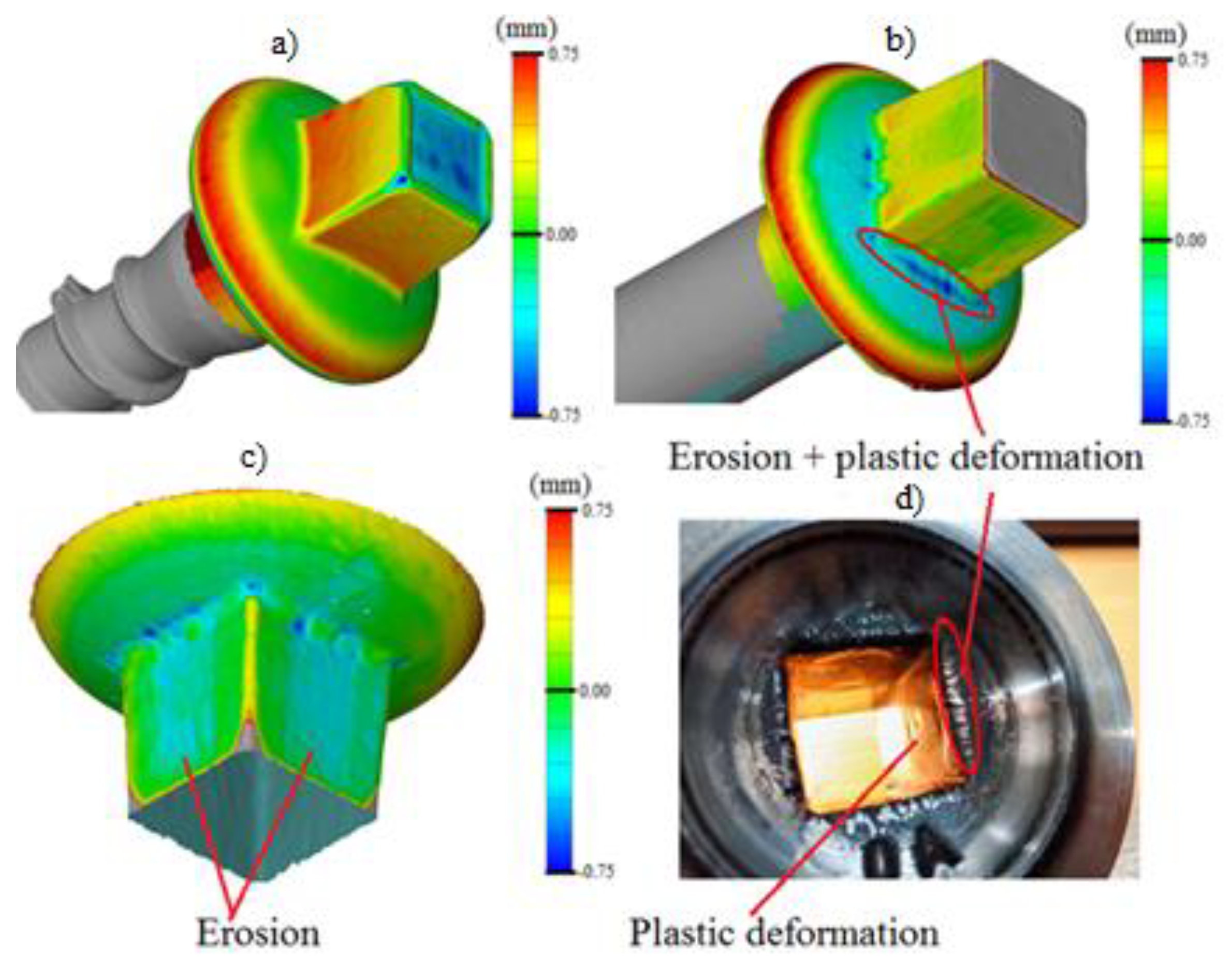
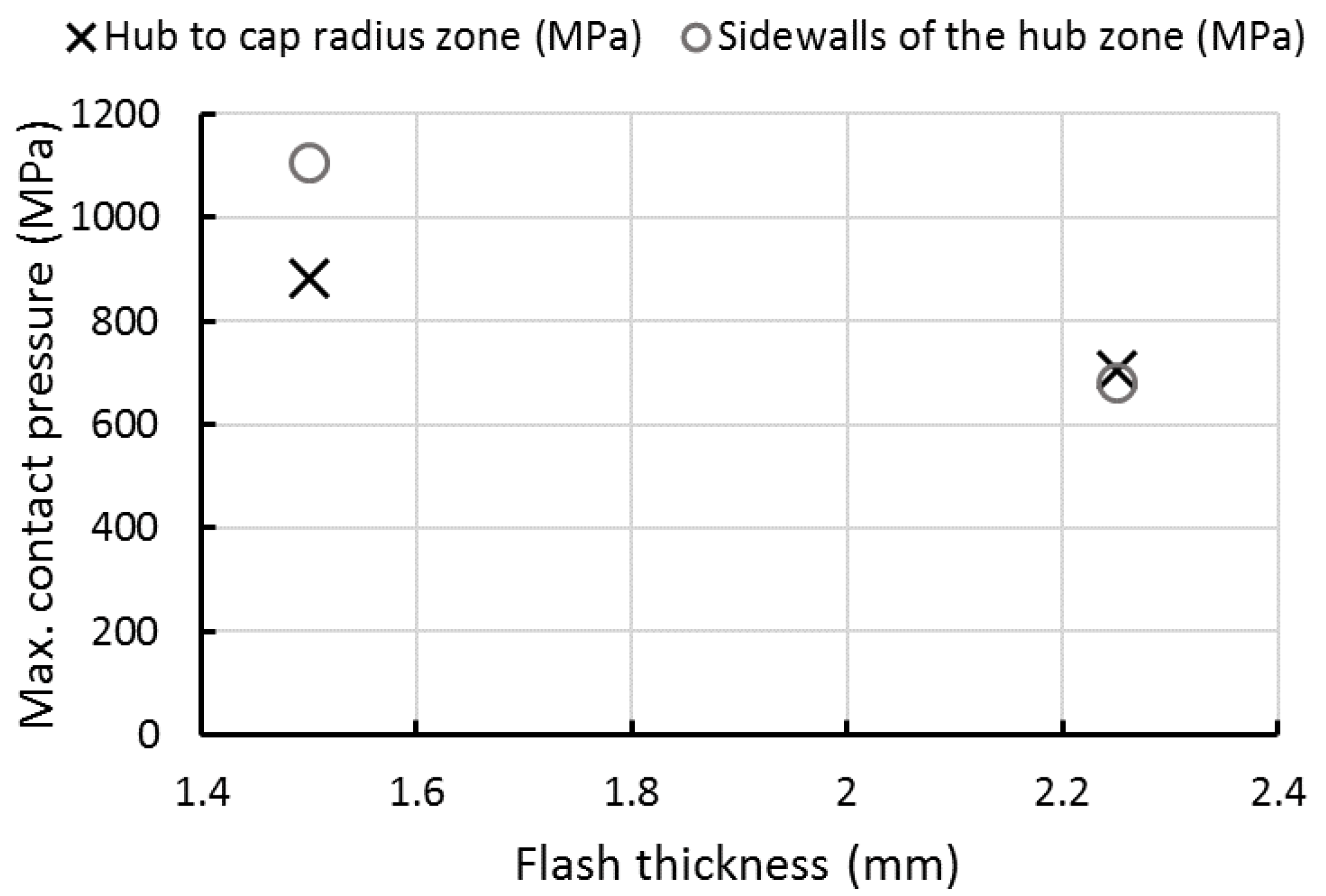
  • The wear is mainly focused on the die splice radii, where the highest contact pressure is concentrated according to the computational simulation results. Specifically, the scanned worn heads showed a transfer of material on the sidewalls of the hub towards the die radius.
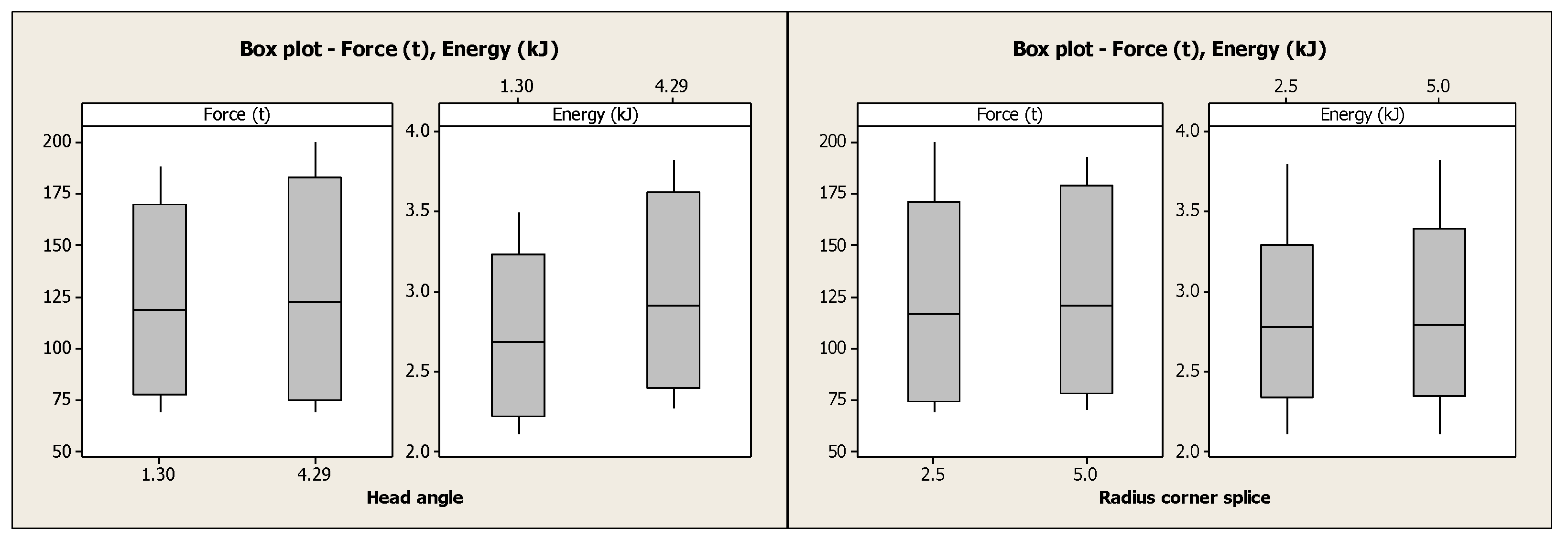
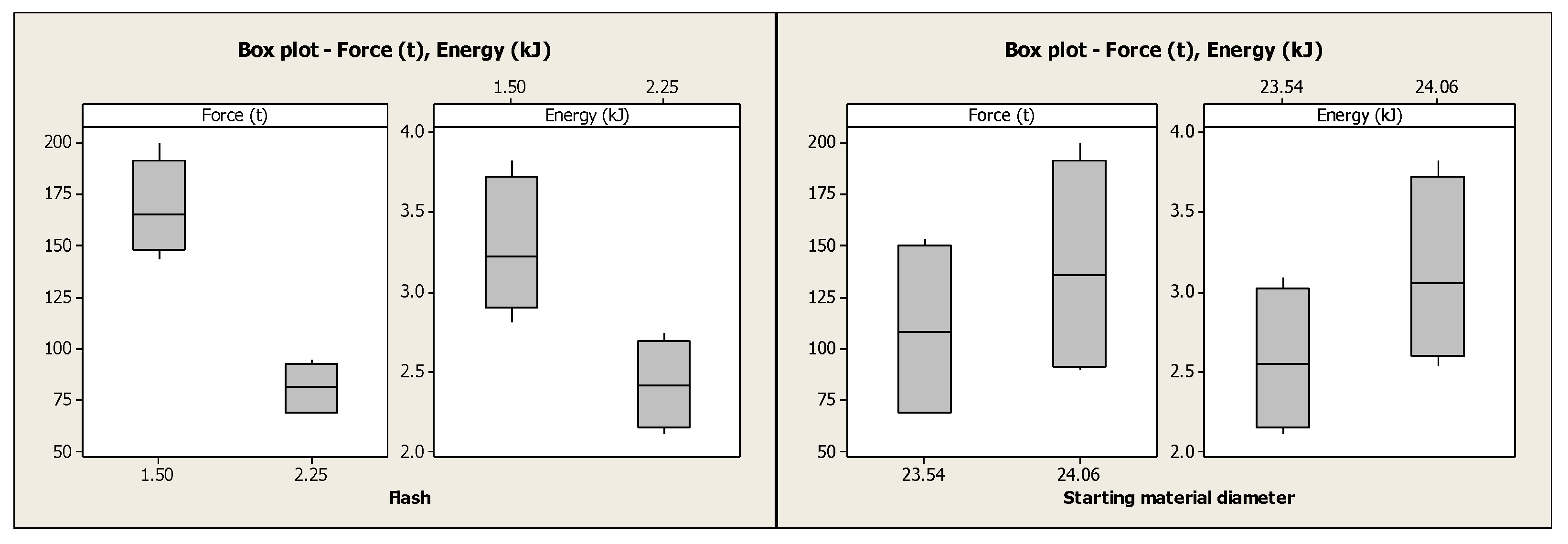
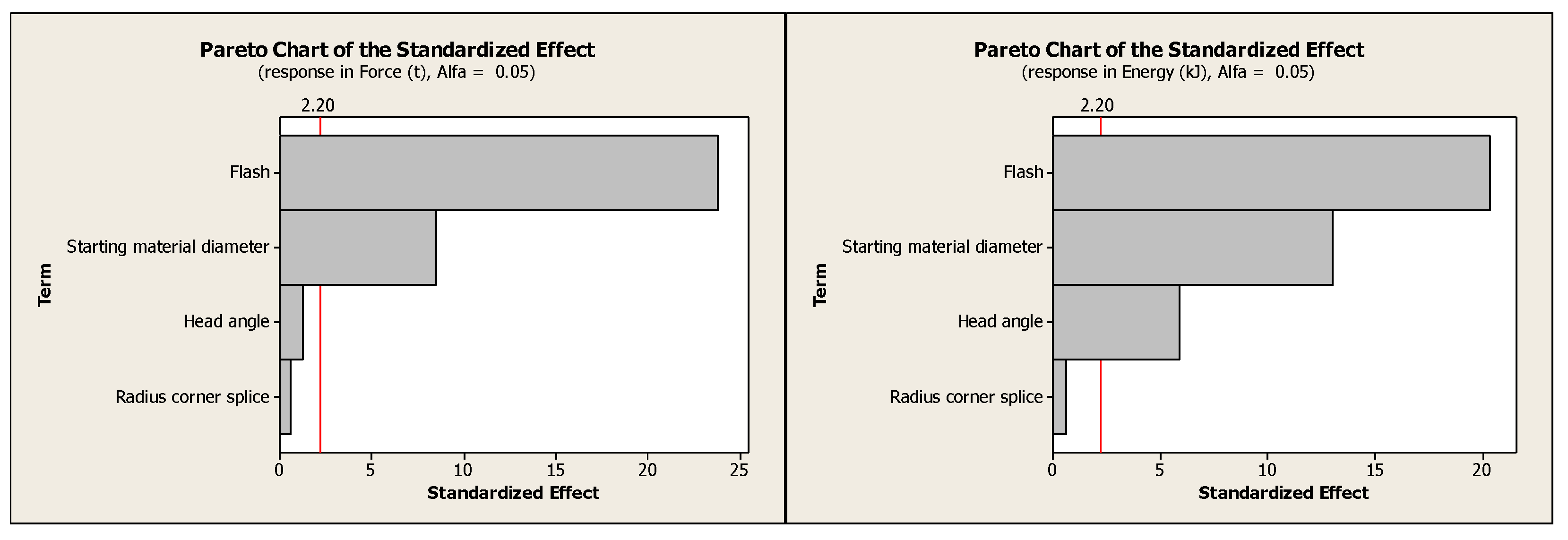
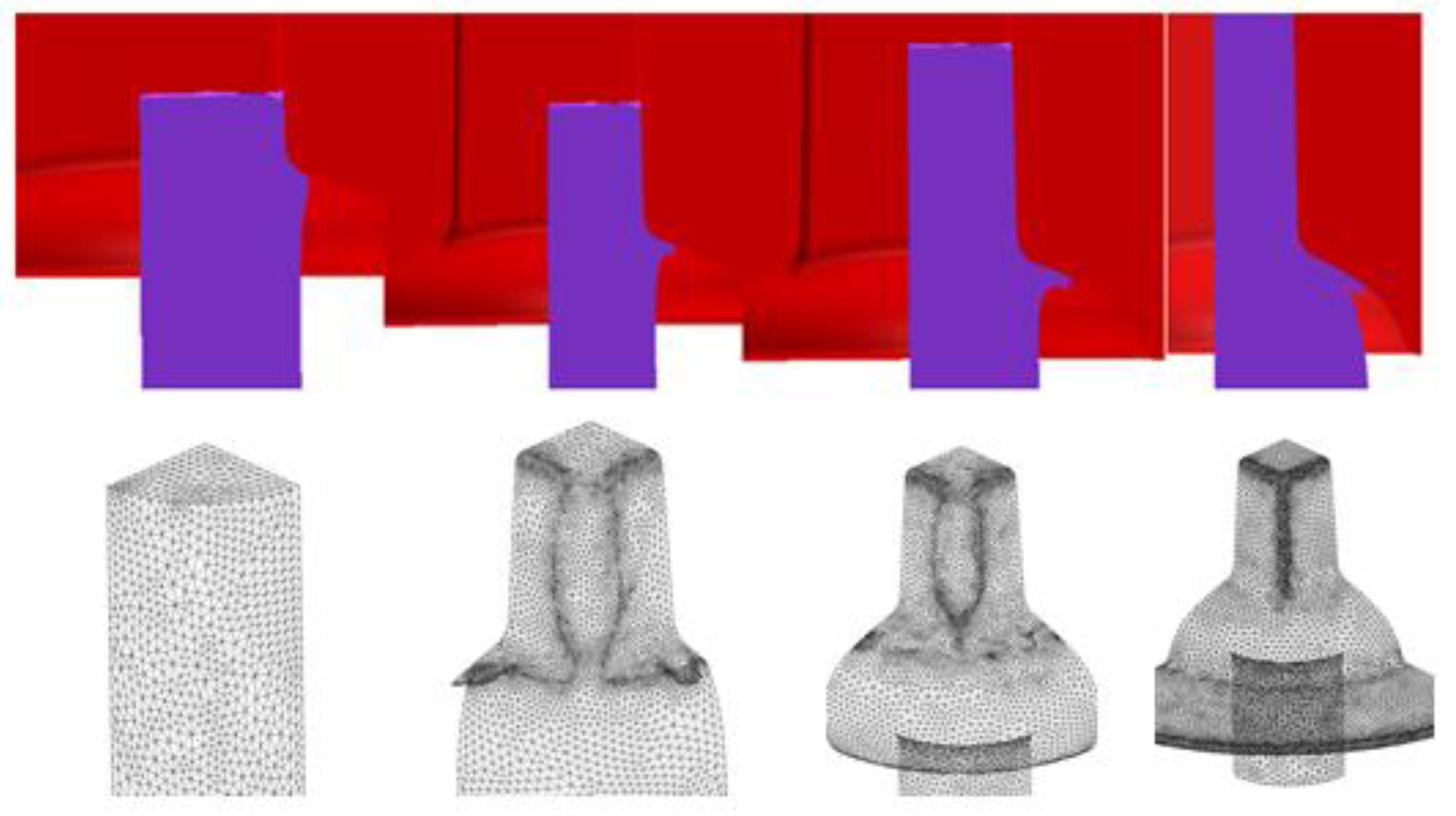
  • The main factor that affects the load and forming energy is the flash thickness, which its value depends on the initial setup. Specifically, the minimum forming energy was obtained for combining a hub wall angle of 1.3°, a starting material diameter of 23.54 mm, and a flash thickness of 2.25 mm. This flash thickness generates a lack of filling at the top vertices of the hub, although this defect does not affect the functionality of the part or its serviceability.
  • An as-received material diameter in the higher range of dimensional tolerance, 24.06 mm, produces folds on the head cap and increases the energy by at least 18%, which increases the probability of failure of the die in a shortened time.

Author Contributions

Conceptualization, N.L.d.L. and D.M.K.; methodology, A.S., G.A. and A.J.S.E.; experimental tests, J.A., A.S. and G.A.; formal analysis, all authors (J.A., G.A., N.A., A.S., A.J.S.E., D.M.K. and N.L.d.L.); investigation, all authors (J.A., G.A., N.A., A.S., A.J.S.E., D.M.K. and N.L.d.L.); resources, D.M.K. and N.L.d.L.; writing—original draft preparation, J.A., D.M.K. and A.J.S.E.; writing—review and editing, all authors; supervision, A.J.S.E. and N.L.d.L.; project administration, D.M.K. and N.L.d.L.; funding acquisition, N.L.d.L. and D.M.K. All authors have read and agreed to the published version of the manuscript.

Funding

This work is supported by the Serra Húnter program (Generalitat de Catalunya) reference number (UPC-LE-304 (2018)) and by the Aeronautics Advanced Manufacturing Center (CFAA). Thanks also are given to special agreement INTI-Faculty of engineering of Bilbao and to university group grant IT 1337-19.

Institutional Review Board Statement

Not applicable.

Informed Consent Statement

Not applicable.

Data Availability Statement

Data sharing is not applicable.

Acknowledgments

The authors acknowledge Mariano Fernández Soler for providing the spike screw samples, María Emilia Boedo for helping with the chemical analysis, Aurelio Martins Dos Santos for performing the liquid penetrant tests, and Facundo Riu for the drawings.

Conflicts of Interest

All the authors who sign this manuscript do not have any conflict of interest to declare. Furthermore, the corresponding author certifies that this work has not been submitted to or published in any other journal.

References

  1. Bonnett, C. Practical Railway Engineering, 2nd ed.; Imperial College Press: London, UK, 2008; p. 7. [Google Scholar]
  2. Schulergroup. Available online: www.schulergroup.com/major/download_center/broschueren_railway/download_railway/railway_broschuere_e.pdf (accessed on 24 May 2021).
  3. Euroforge. Available online: www.euroforge.org/ (accessed on 22 May 2021).
  4. Moreira, T.; Godefroid, L.; de Faria, G.; da Mota Silveira, R. Computational análisis via FEM of Tirefond screws used in the fastening system of railroads aiming to avoid a recurrent failure case. Eng. Fail. Anal. 2019, 106, 104186. [Google Scholar] [CrossRef]
  5. Sánchez Egea, A.; Deferrari, N.; Abate, G.; Martínez Krahmer, D.; López de Lacalle, N. Short-cut method to assess a gross available energy in a medium-load screw friction press. Metals 2018, 8, 173. [Google Scholar] [CrossRef] [Green Version]
  6. Liu, Q.; Guang, X.; Sun, S. The present situation and developing trends of hot closed-die forging. Adv. Mater. Res. 2015, 1094, 365–368. [Google Scholar] [CrossRef]
  7. Sánchez Egea, A.; Martynenko, V.; Abate, G.; Deferrari, N.; Martinez Krahmer, D.; López de Lacalle, N. Friction capabilities of graphite-based lubricants at room and over 1400 K temperatures. Int. J. Adv. Manuf. Technol. 2019, 102, 1623–1633. [Google Scholar] [CrossRef]
  8. Railway Fasteners. Available online: www.railway-fasteners.com (accessed on 21 May 2021).
  9. De Faria, G.; Godefroid, L.; Cândido, L.; Silotti, T. Metallurgical characterization and computational simulation of a screw spike aiming to improve its performance in railways. Eng. Fail. Anal. 2016, 66, 1–7. [Google Scholar] [CrossRef]
  10. Forja Sudamericana. Available online: www.forjasudamericana.com.ar/ (accessed on 21 May 2021).
  11. Gontarz, A.; Pater, Z.; Weroñski, W. Head forging aspects of new forming process of screw spike. J. Mater. Process. Technol. 2004, 153, 736–740. [Google Scholar] [CrossRef]
  12. Van Hai, D.; Hong Hue, D. Finite element simulation and experimental study on internal fracture of railway sleeper screw during cross wedge rolling process. Mater. Sci. Forum 2015, 804, 311–314. [Google Scholar] [CrossRef]
  13. Tomov, B. A new shape complexity factor. J. Mater. Process. Technol. 1999, 92, 439–443. [Google Scholar] [CrossRef]
  14. Tomov, B.; Rossen, R. Shape complexity factor for closed die forging. Int. J. Mater. Form. 2010, 3, 319–322. [Google Scholar] [CrossRef]
  15. Tomov, B.; Radev, R. An example of determination of preforming steps in hot die forging. J. Mater. Process. Technol. 2004, 157, 617–619. [Google Scholar] [CrossRef]
  16. Hu, X.; Wang, L.; Wu, H.; Liu, S. Multi-objective optimization of swash plate forging process parameters for the die wear/service life improvement. Mater. Sci. Eng. 2017, 283, 12–18. [Google Scholar] [CrossRef]
  17. Bayramoglu, M.; Polat, H.; Green, N. Coast and performance evaluation of different surface treated dies for hot forging process. J. Mater. Process. Technol. 2008, 205, 394–403. [Google Scholar] [CrossRef]
  18. Altan, T.; Ngaile, G.; Shen, G. Cold and Hot Forging Fundamentals and Applications, 1st ed.; ASM International: Novelty, OH, USA, 2004. [Google Scholar]
  19. Behrens, B.; Bouguecha, A.; Huskic, A.; Baumer, M.; Paschke, H.; Lippold, L. Increasing the efficiency of forging operations using adjusted tribological surfaces enhanced by hard coatings. Tribol. Online 2016, 1, 432–443. [Google Scholar] [CrossRef] [Green Version]
  20. Krawczyk, J.; Widomski, P.; Kaszuba, M. Advanced complex analysis of the thermal softening of nitrided layers in tools during hot die forging. Materials 2021, 14, 355. [Google Scholar] [CrossRef]
  21. Hirschvogel Automotive Group. Available online: https://www.hirschvogel.com/es/compania (accessed on 28 May 2021).
  22. Prabhu, T. Simulations and experiments of hot forging design and evaluation of the aircraft landing gear barrel Al alloy structure. J. Mater. Eng. Perform. 2016, 25, 1257–1268. [Google Scholar] [CrossRef]
  23. Behrens, B.; Chugreev, A.; Awiszus, B.; Graf, M.; Kawalla, R.; Ullmann, M.; Korpala, G.; Wester, H. Sensitivity analysis of oxide scale influence on general carbon steels during hot forging. Metals 2018, 8, 140. [Google Scholar] [CrossRef] [Green Version]
  24. Bonnemezón, A.; Martinez Krahmer, D. Práctica Industrial de la Forja en Caliente, 1st ed.; Editorial Nueva Librería: Buenos Aires, Argentina, 2012. [Google Scholar]
  25. Matweb Material Property Data. Available online: www.matweb.com (accessed on 25 September 2021).
  26. Hatzenbichler, T.; Harrer, O.; Buchmayr, B.; Planitzer, F. Effect of different contact formulations used in commercial FEM software packages on the results of hot forging simulations. Metall. Ital. 2009, 102, 11–15. [Google Scholar]
  27. Abate, G.; Perez, D.; Martinez Krahmer, D.; Bigot, R.; Radev, R. Forja en caliente en matriz cerrada: Influencia del flash y el peso del material de partida sobre la fuerza de conformado y el llenado de la matriz. In Proceedings of the Anales del 15º Congreso de Metalurgia y Materiales, Concepción, Chile, 17–20 November 2015. [Google Scholar]
  28. Olvera, D.; López de Lacalle, N.; Urbikain, G.; Lamikiz, A.; Rodal, P.; Zamakona, I. Hole making using ball helical milling on titanium alloys. Mach. Sci. Technol. 2012, 16, 173–188. [Google Scholar] [CrossRef]
Figure 1. Railway fasteners: (a) components of the head and (b) main geometric variables.
Metals 11 01834 g001
Figure 2. Head forming dies resulting from the hub dimensions in mm.
Metals 11 01834 g002
Figure 3. Screw spike with a vertex underfill for 2.25 mm burr cannel.
Metals 11 01834 g003
Figure 4. Box plots for geometric parameters according to the standard.
Metals 11 01834 g004
Figure 5. Box plots for the analyzed process parameters.
Metals 11 01834 g005
Figure 6. Influence order of the operating parameters on load and energy of the forming process.
Metals 11 01834 g006
Figure 7. Sequence of fold formation at the cap of the head of the screw spike.
Metals 11 01834 g007
Figure 8. Folds exposed by penetrating inks on the cap of the screw.
Metals 11 01834 g008
Figure 9. Contact pressure along the forming process of the head of the screw spike.
Metals 11 01834 g009
Figure 10. The 3D scan images were analyzed with GOM Inspector to determine the dimensional deviation between samples formed on new and worn dies.
Metals 11 01834 g010
Figure 11. Maximum contact pressure related to the flash thickness and most degraded areas.
Metals 11 01834 g011
Table 1. CAD dimensions of the head of the spike screw.
GeometryD2 min.–D2 max.D1 min.–D1 max.R min.–R max.
CAD dimensions (mm)22–2320–212.5–5
Table 2. Chemical composition of the material of the tested screw spikes.
Sample%C%Mn%Si%P%S
Screw spike0.31 ± 0.020.71 ± 0.060.17 ± 0.06<0.010<0.009
Table 3. Mechanical properties of SAE 1030 [25].
MaterialYield Strength (MPa)Ultimate Tensile Strength (MPa)Total strain (%)Brinell Hardness (HB)
SAE 103034555032179
Table 4. Simulations of the forming process of the head of the screw spike.
SimulationsDiesAs-Received Material
Dmin. (mm)
As-Received Material
Dmax. (mm)
Min. Burr Thickness
(mm)
Max. Burr Thickness
(mm)
16423.5424.061.502.25
Table 5. Convergence analysis to establish meshing conditions.
Simulation ResponseComplete Geometry¼ Geometry
First Order 1.0 mmHigh Order 1.8 mmHigh Order 1.0 mmHigh Order 0.7 mmHigh Order 1.0 mm
Configuration Metals 11 01834 i001 Metals 11 01834 i002 Metals 11 01834 i003 Metals 11 01834 i004 Metals 11 01834 i005
Force (t)158.5181.9(*)(**)187.2
Simulation time (h)4.25.611.517.715.9
Elements23,076715823,07646,50011,176
(*) The simulation found the stop criterion (20 h) with a progress of 19.6%. (**) The simulation found the stop criterion (20 h) with a progress of 7.4%.
Table 6. Results of the p-value for the analyzed forging parameters.
Factorp-Value
Load (t)Energy (kJ)
Head angle0.2330.000
Hub to cap radius0.5690.551
As-received material diameter0.0000.000
Flash thickness0.0000.000
Publisher’s Note: MDPI stays neutral with regard to jurisdictional claims in published maps and institutional affiliations.

