Article

Technology Innovation for the Manual Laser Cladding of High-Alloy Tool Steels

1
Institute for Machine Tools and Production Processes (IWP), Chemnitz University of Technology, Reichenhainer Straße 70, 09126 Chemnitz, Germany
2
Leibniz Institute for Solid State and Materials Research Dresden, Institute for Complex Materials, Helmholtzstr. 20, 01069 Dresden, Germany
*
Author to whom correspondence should be addressed.
Metals 2021, 11(11), 1820; https://doi.org/10.3390/met11111820
Submission received: 27 September 2021 / Revised: 9 November 2021 / Accepted: 10 November 2021 / Published: 12 November 2021
(This article belongs to the Special Issue Electroheat Models and Analysis of Metallic Materials)

Abstract

:
This paper presents the development and successful application of an inductive preheating system running simultaneously with the manual laser cladding process in order to enable the repair of high-alloy tool steels having a highly limited weldability. In this study, the design and optimization of a suitable inductor as well as the analysis of the welding process were carried out by means of FE-simulation in order to generate material deposition without imperfections. Parameter variation studies were conducted while parallel modifying the generator power resulting in different preheating temperatures. These examinations showed that by using appropriate process parameters and an inductive preheating temperature of 200 °C, crack- and pore-free deposition layers could be produced on the commercial high-alloyed PM steel Elmax. This result can be explained by FE-simulation demonstrating that the cooling rate was halved in the weld and in the heat-affected zone. In conclusion, this study shows the high potential of the developed technical innovation for the manual laser cladding of high-performance tools.

1. Introduction

Tools, which are used for injection molding, forming or cutting, are subject to a high level of wear load during use. This often leads to their failure and, thus, to a downtime in production. In addition, the increasing processing of high-strength alloys and composite materials for the automotive industry, mechanical and plant engineering or power engineering results in a reduced tool life. For these cases, laser deposition welding has proven to be a suitable process and occupies a key position in modern toolmaking [1]. In order to extend the service life and develop high-performance tool components, deposition and repair welding represents a cost and resource-saving alternative to the continuous purchase of new tools [2]. By using a suitable welding process and filler material, hard and wear-resistant deposition layers with sufficient toughness can be produced so that both, worn areas and chipped edges, can be rebuilt. The process of repair welding is performed by starting with removing the damaged or worn material by milling or grinding and then polishing the part to obtain a bright and clean surface. Subsequently, a welding process is used to apply material layer by layer onto the substrate.
In manual laser deposition welding, thin wires with diameters between 0.15 and 0.8 mm are usually used as filler material, which are fed by hand by the operator. Figure 1 shows the principle of laser cladding. The wire and the substrate are molten by the directed pulsed laser beam creating common weld pool. Due to the limited heat transfer into the substrate, the melt solidifies rapidly, forming a punctiform material deposit. A continuous feed in the direction of an axis creates a line-shaped deposition weld (Figure 1a). By placing several lines next to each other, a two-dimensional material deposition is generated as one layer. By means of stacking several layers on top of each other, deposition welding is continued until a sufficient oversize is achieved (Figure 1b). Finally, the original shape of the tool is restored by post-processing, such as milling or spark erosion.
To meet the increasing demands on tools, high-alloy tool steels e.g., powder-metallurgical produced steels are progressively being used. However, their repair poses a great challenge, as these steels are considered to have limited weldability. This means that during welding processing high-alloy tool steels show a high susceptibility to cracking due to their special alloy compositions, as revealed in Figure 2. Increased residual stresses result from the high temperature gradients during cooling or from phase transformations, which can ultimately lead to cracking (Figure 2a), failure of the weld seam or to tearing out the whole volume of applied material (Figure 2b). This can already happen with comparatively small claddings of (10 × 10) mm2.
In such a case, the tool must then be reprocessed and welded anew. If the tool is used again despite these defects, the cracks represent potential starting points for new defects and the future service life is limited from the outset.
One way to prevent cracking during welding is to preheat the substrate [3,4,5]. Consequently, the cooling time of both the weld metal as well as the heat-affected zone (HAZ) is extended, residual stresses are lowered and, thus, the risk of cold cracking is reduced. In practice, this can be achieved by various methods. One possibility of preheating is a hot plate [6,7]. In contrast to preheating in a furnace, this allows continuous heat input during the process, but heats the entire workpiece. Therefore, it is only suitable for smaller parts, which are not prone to heat. By a scanner optics it possible to preheat the part locally to a certain temperature with the laser beam [8,9]. This process precedes welding, since it uses the same heat source, but allows more precise preheating in contrast to the hot plate. Heating with a pre-running inductor makes it possible to preheat the substrate simultaneously with the welding process. This device with a single coil winding is used, for instance, during the automatic process of cladding rotationally symmetrical components by [10,11] but also flat workpieces [12] where cracks, peeling off of deposited tracks and other surface damage was prevented. If the geometry of the workpiece permits, internal field heating with an encompassing inductor is also possible to achieve welds without cracks [13].
The aim of the present work was to develop a suitable inductor as well as a technology for this manual process to generate deposition welds on high-alloy tool steel and powder metallurgical steel without cracks or other imperfections.

2. Materials and Methods

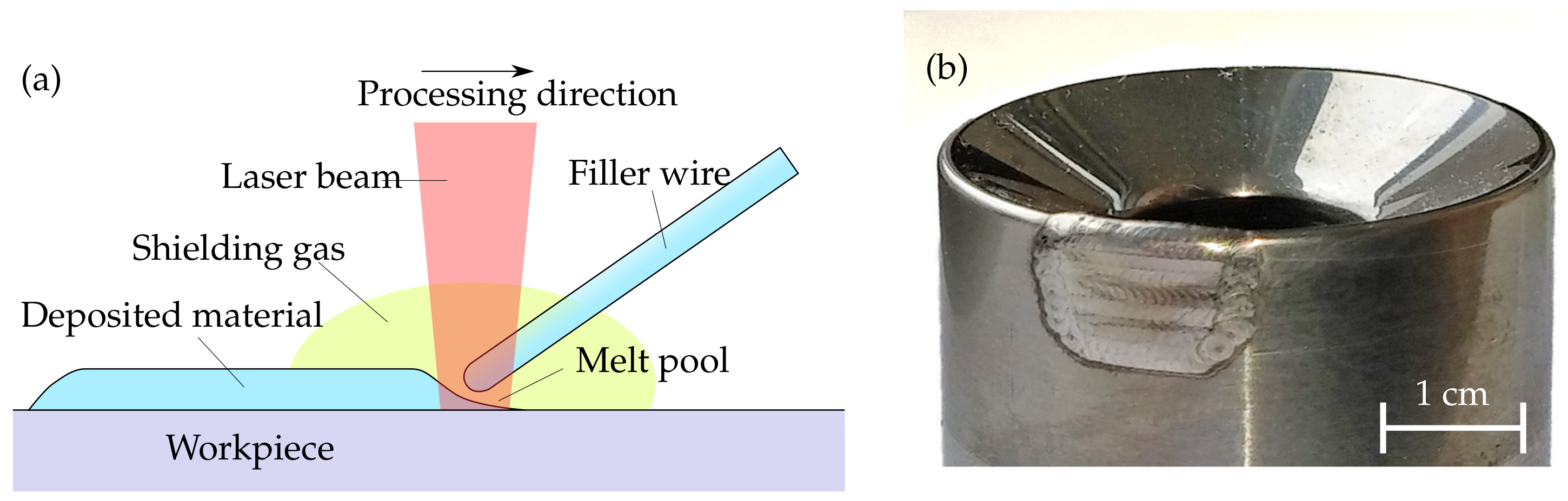
2.1. Experimental Setup

The welding tests were carried out on an experimental setup for manual laser cladding (Figure 3). This includes a TruPulse 556 Nd:YAG laser (TRUMPF GmbH + Co. KG, Ditzingen, Germany), which was operated in pulse mode (rectangular) with a power of 2800 W, a pulse frequency of 8.9 Hz and a pulse duration of 8 ms. That equals a pulse energy of 22.4 J and an average power of about 200 W. The focal diameter was 1.5 mm and the welding speed 340 mm/min. The process parameters were selected in such a way that the filler metal could be welded properly. This means that incomplete melting, bonding defects or spattering are prevented. For preheating an induction medium-frequency generator MFG 10 (EMAG eldec Induction GmbH, Dornstetten, Germany) with a maximum output of 10 kW and an operating frequency of 12 kHz was chosen.
On the inductor, the soft magnetic composite material Alphaform MF (Fluxtrol Inc., Auburn Hills, MI, USA) was used to direct the magnetic field. Temperature was measured with an CTlaser 3ML pyrometer (Optris GmbH, Berlin, Germany). Since this is a manual process and the person performing the welding has an influence on the welding result, all tests were done by the same operator. In this way, comparability of the results is ensured [14].

2.2. Materials Used

The substrate material investigated in this study is the high chrome steel grade Elmax (Uddeholms AB, Hagfors, Sweden). This powder metallurgical tool steel is commonly used in particular for injection molds and cutting tools. Its chemical composition is shown in Table 1. The dimensions of the samples are (200 × 45 × 15) mm3 and have been hardened to 62 HRC. A the material investigated [15,16].
A conventional high-performance wire QuFe60 (1.3348, quada V+F) with a diameter of 0.6 mm was used as filler material. It is a widely used alloy for repair welding that requires high hardness. The chemical composition is specified in Table 2. The resulting hardness after laser cladding is 60–64 HRC.
For the simulation of the inductive heating of the substrate as well as of the deposition welding process, material parameters as a function of temperature are required. For this purpose, the software JMatPro was used, which is a field-proven tool to calculate temperature-dependent material properties. Figure 4 and Figure 5 show the results for the specific heat capacity and the thermal conductivity of Elmax and QuFe60, which are particularly relevant for the thermal calculations. The data obtained were implemented in the material models used for the simulation.
The material data for copper, of which the induction coil is made of, are required for the electromagnetic simulation and were obtained from the COMSOL database. The properties of the soft magnetic composite Alphaform MF were taken from the official data sheet [17].

2.3. FE Simulation of the Preheating Process

To find a compatible coil geometry FE simulation of the preheating process is required. An inductor geometry suitable for the application has to meet three essential criteria. First, the coil must heat the area around the welding spot to about 200 °C to achieve sufficient preheating of the substrate. Occasionally, defects on common tools occur at narrow points or undercuts. As a second criteria, the magnetic field around the inductor must be located to heat only the area below the inductor and not the surrounding regions. Third, it must be possible for the operator to continue welding without being obstructed by the inductor, and the laser beam must reach the surface of the substrate unhindered.
Taking these criteria into account, a coupled electromagnetic-thermal simulation model with frequency-transient analysis was built in the FEA software COMSOL Multiphysics 5.4. The substrate was a plate with dimensions of (300 × 50 × 20) mm3. As an induction coil, different geometries were designed using CAD and imported into COMSOL. Within the heat transport module, a translational relative motion between coil and substrate with the magnitude of the later welding speed was added to predict the real heat distribution in the workpiece. The system to be solved is given by the equations
j ω σ ( T ) A + × ( μ 1 × A ) = J 0
ρ C p T t · k T = Q ( T , A )
where ρ is density, C p is the specific heat capacity, k is the thermal conductivity, Q is the inductive heating and J 0 is the source current density. The multiphysics and coupling aspects of the electromagnetic as well as the heat transfer effects are described by the following equation system.
ρ C p T t + ρ C p u · T = · ( k T ) + Q e
Q e = Q r h + Q m l
Q r h = 1 2 R e ( J · E * )
Q m l = 1 2 R e ( i ω B · H * )
where u is the vector of the translational motion, Q e are the electromagnetic losses, Q r h are the resistive losses and Q m l are the magnetic losses. B is the magnetic flux density and H is the magnetic field density. The set coil current was 1500 A (zero-to-peak) and the working frequency according to the generator was set to 15 kHz. For the mesh, four boundary layers were added to the edges of the inductor coil as well as to the substrate surface to sufficiently depict the skin effect. The coil, the soft magnetic composite and the surrounding air consisted of tetrahedral elements. The substrate contained a structured hexahedral mesh. Depending on the specific inductor geometry, the number of elements was about 95,000 and the solution of each model took about 1 h 20 min on an Intel Xeon E3-1270 v5 4-core unit with 64 GB of RAM.

2.4. FE Simulation of the Welding Process

Subsequently, a model for the combined procedure of preheating and welding process was built. For this case, the FEA software Simufact Welding 8 was used to build a thermomechanically coupled model. The preheating of the substrate previously calculated in COMSOL was included as a heat source in the model in accordance with its power and distribution. The dimensions of the substrate were (50 × 40 × 20) mm3 and the deposition weld consisted of 26 individual spots each with a diameter of 1.7 mm and a height of 0.36 mm. The geometry was determined from microsections of single spot welds. In the software, the laser is modeled using a surface heat source. The goal of the used heat source concept is to realistically model the isothermal surface of the melt pool and the heat flow through the surface. Effects of the melt pool flow are indirectly considered [18]. The main parameters of the heat source are noted in Table 3.
The complete weld time in the model with a pulse frequency of 8.9 Hz was 2.92 s. In order to adequately depict the cooling and microstructural transformations, a total analysis time of 8 s was chosen. The number of elements was about 210,000, with the material deposition consisting of tetrahedral elements and the substrate of a structured hexahedral mesh. The solution took about 12 h 30 min on the previously mentioned computing device.

3. Results and Discussion

3.1. Testing of a Suitable Coil Geometry

For the simulation of the preheating in dependence on the inductor coil geometry, in total 16 different designs were investigated. Thereby, some coils showed insufficient heating of the substrate due to a too low inductor efficiency. In application this would require an oversized generator or the existing equipment would not be sufficient to ensure adequate preheating. Some other coils only sufficiently heated the regions behind the welding area and, thus, would only achieve post-heating of the deposition seam. The best result was obtained with a narrow C-shaped inductor, which achieves adequate preheating despite feeding at welding speed and being located directly in front of the weld zone. Furthermore, accessibility to the welding area is maintained for the wire feed as well as for the laser beam. The temperature distribution over time is displayed in Figure 6.
Subsequently, a similar inductor was built according to the knowledge gained from the electromagnetic simulation. It was bent from a (6 × 4) mm2 hollow copper profile and provided with the soft magnetic composite Alphaform MF. To determine the achievable surface temperature as well as to validate the simulation model, dynamic preheating tests were carried out firstly. This means that heating takes place during translational relative movement between substrate and induction coil. For this purpose, the induction coil and the pyrometer were mounted on the Z-axis of the welding machine. The measuring spot of the pyrometer was placed at the point where the laser beam hits the substrate. The coupling distance between the inductor and substrate was 3 mm. This prevents collisions between the inductor coil and the weld metal during later laser deposition welding. The substrate was painted black. An emissivity of 0.97 was assumed for the measurement. The temperature measurement began after the simultaneous start of the feed rate and inductive heating. The results of the measurements are presented in Figure 7.
The results in the diagram show that an almost constant temperature is established after about 6 s, regardless of the power. For deposition welding, this means that stationary preheating for about 3 to 5 s may be necessary in order to avoid imperfections at the beginning of the weld. Furthermore, with use of the inductor coil and a set generator power of 80% it is possible to achieve a stable preheating level slightly above 200 °C. In addition, the dataset shows that the simulation model correlates well with the temperature measurements.

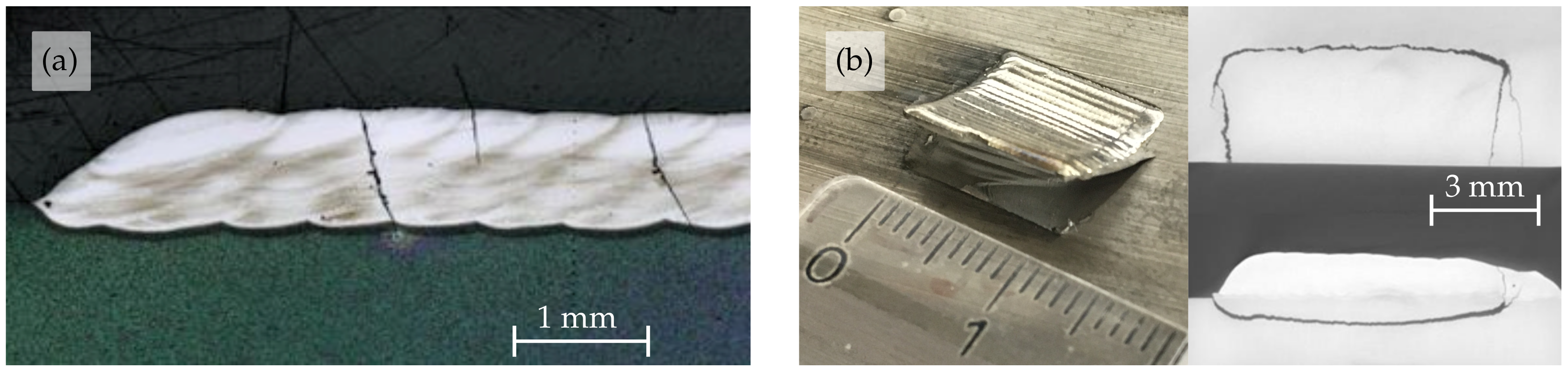
3.2. Welding Results with Preheating

Following the heating tests, deposition welding experiments with inductive preheating were carried out. For this purpose, areas of (15 × 15) mm2 with an overlap of 50% were applied as a benchmark. This means that within one layer, each deposition weld overlaps the preceding one by 50%, resulting in an uniform bond.
Figure 8a shows the result of a deposition welding of 10 layers on the powder metallurgical steel. Neither on the surface of the weld nor in the substrate any cracks were detected. The CT scan executed on a GE Phoenix Nanotom M of a corresponding deposition weld confirmed that no cracks, pores or other imperfections in the weld metal or in the base material were present (Figure 8b). A direct comparison with initial deposition welds (Figure 2) without preheating shows that the tendency to cracking by using the same laser parameters was significantly reduced by the tailored inductive preheating. Similar results were also observed by [12] when deposition welding stellite onto a different tool steel with conditional weldability. It can be assumed that the simultaneous preheating approach provides more reliable crack prevention than preliminary local heating of the substrate [8]. Additionally, welding tests carried out on a real forming tool were successful by revealing no imperfections in the welded material, so that a longer service life of the tool can be expected afterwards (Figure 8c).

3.3. Simulation Results of the Combined Process

A comparison of the results generated with Simufact Welding without preheating on the one hand and with preheating on the other hand shows, first of all, the effect of applying the induction tool in slowing down the rapid cooling of the weld metal and substrate. Figure 9 illustrates a sectional view through the entire weld consisting of 26 single welding spots.
The parameter shown in Figure 9 is the T8/5-rate. This parameter describes the cooling rate in the temperature window between 800 °C and 500 °C, where the most important microstructural transformations take place within the material. The welding process in the simulation model was performed from right to left, meaning that the welding spots on the right of the image were generated firstly. The cooling rate of these points is slightly higher than that of the rest of the weld. This is due to the fact that the workpiece is still colder at the beginning than at the time when several spot welds have already been deposited. It can be seen that preheating approximately reduces the cooling rate of the weld metal and also in the HAZ of the substrate around the weld by half. Despite this delayed cooling in the weld metal, the desired hardness of the deposition layer and, thus, a corresponding wear resistance can still be maintained, what was determined in experimental tests (not shown here).
The thermomechanical analysis of the simulation model provides explanations why the tendency to cold cracking in the weld metal and substrate decreases with preheating. Figure 10 displays the sectional view through the seam transversely to the welding direction presenting the equivalent stresses in the base material and in the weld metal.
The results of the simulation model show that after the deposition welding process, the maximum residual stresses occur in the HAZ (Figure 10a). This is consistent with the failure patterns of the initial welding tests, in which the deposited material was torn from the substrate (Figure 2b). Inductive preheating of the substrate slows down the cooling of the weld and the HAZ. This results in significantly lower stresses in the substrate and weld seam, what also substantially reduces the risk of failure in the base material (Figure 10b).

4. Conclusions

The results of the presented investigations show that crack-free welding of high-alloy tool steels is possible by implementing a tailored inductive preheating tool to the manual laser cladding process. This steel group is considered to have conditional weldability and is susceptible to severe cracking during welding, which often leads to failure of the weld. Simultaneous heating with the developed C-shaped inductor eliminates the necessity of upstream complete heating of large workpieces, reducing process time, and energy consumption. It was found that with the experimental setup, a nearly constant preheat temperature could be achieved after about 6 s during the welding motion regardless of the generator power. Due to the high quality of the deposition welds on the commercial high-alloyed PM steel Elmax, repairs on tools are feasible that were previously difficult to achieve. The explanation for this is the lower cooling rate in the range between 800 and 500 °C, which is already approximately halved at 200 °C preheating, as shown by the simulation model. Even small cracks, formerly accepted by end users, can be eliminated leading to the expectation that tools repaired with the technology developed will have a longer service life before they fail again. In conclusion, this study shows the high potential of the developed preheating tool to be applied during manual laser cladding of materials with a high susceptibility to cracking.

Author Contributions

Conceptualization, J.K., J.Z. and A.F.; investigation, J.K. and A.F.; software, J.K.; writing—original draft preparation, J.K.; writing—review and editing, J.K., J.Z. and V.K.; visualization, J.K. and J.Z.; supervision, V.K.; project administration, J.K. and A.F.; funding acquisition, J.K., J.Z., A.F. and V.K. All authors have read and agreed to the published version of the manuscript.

Funding

The publication of this article was funded by Chemnitz University of Technology.

Institutional Review Board Statement

Not applicable.

Informed Consent Statement

Not applicable.

Data Availability Statement

Not applicable.

Acknowledgments

This work was supported by German Federal Ministry of Economics and Technology (BMWi) and German Federation of Industrial Research Associations (AiF) within the ZIM initiative. The authors are grateful to their project partners LPT Laserpräzisionstechnik GmbH and quada V+F GmbH as well as to N. Geißler for technical support, material provision and helpful discussions.

Conflicts of Interest

The authors declare no conflict of interest.

References

  1. Jhavar, S.; Paul, C.; Jain, N. Causes of failure and repairing options for dies and molds: A review. Eng. Fail. Anal. 2013, 34, 519–535. [Google Scholar] [CrossRef]
  2. Toyserkani, E.; Khajepour, A.; Corbin, S.F. Laser Cladding, 1st ed.; CRC Press: Boca Raton, FL, USA, 2004. [Google Scholar]
  3. Šturm, R.; Štefanikova, M.; Steiner Petrovič, D. Influence of pre-heating on the surface modification of powder-metallurgy processed cold-work tool steel during laser surface melting. Appl. Surf. Sci. 2015, 325, 203–210. [Google Scholar] [CrossRef]
  4. Preciado, W.T.; Bohorquez, C.E.N. Repair welding of polymer injection molds manufactured in AISI P20 and VP50IM steels. J. Mater. Process. Technol. 2006, 179, 244–250. [Google Scholar] [CrossRef]
  5. Cooper, K.P.; Slebodnick, P. Recent Developments in Laser Melt/Particle Injection Processing. J. Laser Appl. 1989, 1, 21–29. [Google Scholar] [CrossRef]
  6. Shi, R.R.; Chen, S.Y.; Peng, Y.G.; Zhang, Z. Effect of Preheating Temperature on Microstructure of Fe Based Alloy Coating by Laser Direct Metal Deposition. Key Eng. Mater. 2016, 703, 94–99. [Google Scholar] [CrossRef]
  7. Legesse, F.; Kapil, S.; Chabra, R.; Sharma, A.; Karunakaran, K.P. In-Situ Preheating in Hybrid Layered Manufacturing for Tooling Elements. In Proceedings of the Solid Freeform Fabrication Symposium, Austin, TX, USA, 8–10 August 2016; pp. 438–447. [Google Scholar]
  8. Alimardani, M.; Fallah, V.; Khajepour, A.; Toyserkani, E. The effect of localized dynamic surface preheating in laser cladding of Stellite 1. Surf. Coat. Technol. 2010, 204, 3911–3919. [Google Scholar] [CrossRef]
  9. Raj, D.; Das, B.; Maity, S.R. Preheating Path Selection through Numerical Analysis of Laser-Aided Direct Metal Deposition. In Recent Advances in Mechanical Engineering; Springer: Singapore, 2021; pp. 211–220. [Google Scholar] [CrossRef]
  10. Wang, D.; Hu, Q.; Zheng, Y.; Xie, Y.; Zeng, X. Study on deposition rate and laser energy efficiency of Laser-Induction Hybrid Cladding. Opt. Laser Technol. 2016, 77, 16–22. [Google Scholar] [CrossRef]
  11. Kotlan, V.; Hamar, R.; Pánek, D.; Doležel, I. Model of depositing layer on cylindrical surface produced by induction-assisted laser cladding process. Open Phys. 2017, 15, 971–978. [Google Scholar] [CrossRef] [Green Version]
  12. Tuominen, J.; Vuoristo, P. Induction heating unit equipped with closed-loop PID controller; versatile tool in laser cladding. In Proceedings of the International Congress on Applications of Lasers & Electro-Optics, Orlando, FL, USA, 29 October–1 November 2007; Laser Institute of America: Orlando, FL, USA, 2007. [Google Scholar] [CrossRef]
  13. Nowotny, S.; Scharek, S.; Naumann, T.; Zieris, R.; Beyer, E. Laser based hybrid techniques for surface coating. In Proceedings of the International Congress on Applications of Lasers & Electro-Optics, Scottsdale, AZ, USA, 14–17 October 2002; Laser Institute of America: Orlando, FL, USA, 2002. [Google Scholar] [CrossRef]
  14. Capello, E.; Previtali, B. The influence of operator skills, process parameters and materials on clad shape in repair using laser cladding by wire. J. Mater. Process. Technol. 2006, 174, 223–232. [Google Scholar] [CrossRef]
  15. BÖHLER Edelstahl GmbH & Co KG. SCHWEISSEN IM WERKZEUGBAU—Anleitung zum Schweißen von Kaltarbeitsstählen, Warmarbeitsstählen, Schnellarbeitsstählen, Kunststoffformenstählen Einschließlich der PM-Hochleistungswerkstoffe; Bohler Edelstahl GmbH & Co KG: Kapfenberg, Austria, 2008; p. 24. [Google Scholar]
  16. Hu, L.; Huang, J.; Li, Z.; Wu, Y. Effects of preheating temperature on cold cracks, microstructures and properties of high power laser hybrid welded 10Ni3CrMoV steel. Mater. Des. 2011, 32, 1931–1939. [Google Scholar] [CrossRef]
  17. Fluxtrol Inc. Alphaform MF Data Sheet. Available online: https://fluxtrol.com/inc/pdf/AlphaForm-MF-Specs.pdf (accessed on 22 September 2021).
  18. Documentation of Simufact Welding 8; Simufact Engineering GmbH: Hamburg, Germany, 2019.
Figure 1. (a) Principle of manual laser deposition welding. (b) Repaired tool before machining.
Metals 11 01820 g001
Figure 2. (a) Crack formation in the weld metal. (b) Crack formation in the substrate.
Metals 11 01820 g002
Figure 3. (a) Schematic view of the setup. (b) Experimental setup of the welding table with 3-axis positioning unit. (c) Induction generator used for the experiments.
Metals 11 01820 g003
Figure 4. Calculated specific heat capacity and thermal conductivity of the substrate material Elmax in dependence on temperature.
Metals 11 01820 g004
Figure 5. Calculated specific heat capacity and thermal conductivity of the filler material QuFe60 in dependence on temperature.
Metals 11 01820 g005
Figure 6. (a) Temperature distribution in the substrate over time when heated with a C-shaped inductor coil. (b) View of the fabricated C-shaped inductor for welding experiments.
Metals 11 01820 g006
Figure 7. Measured profile of the preheating temperature in the area of the welding zone at different power settings of the induction generator.
Metals 11 01820 g007
Figure 8. (a) 10-layer deposition welding with inductive preheating. (b) CT scan of the cut specimen. (c) Real forming tool repaired aided by inductive preheating.
Metals 11 01820 g008
Figure 9. Sectional view along the welding seam of the simulated process with T8/5-rate: (a) Deposition welding without preheating. (b) Deposition welding with simultaneous inductive preheating.
Metals 11 01820 g009
Figure 10. Sectional view transversely to the welding direction with equivalent stresses: (a) Deposition welding without preheating. (b) Deposition welding with simultaneous inductive preheating.
Metals 11 01820 g010
Table 1. Tabular overview of chemical composition of Elmax (in wt %).
CCrMnMoVSiFe
1.7180.31.03.00.8bal.
Table 2. Tabular overview of chemical composition of QuFe60 (in wt %).
CCrMoVWSiMnFe
1.04.08.31.81.90.40.4bal.
Table 3. Specifications of the normally distributed area heat source for the laser process in the simulation model.
RadiusDepthGaussian ParameterSpeedPowerEfficiency
1.1 mm0.39 mm3.0340 mm/min2800 W0.72
Publisher’s Note: MDPI stays neutral with regard to jurisdictional claims in published maps and institutional affiliations.

