
Thermophysical Properties of Electric Arc Plasma and the Wire Melting Effect with Lanthanum and Sulfur Fluorides Addition in Wire Arc Additive Manufacturing


Abstract
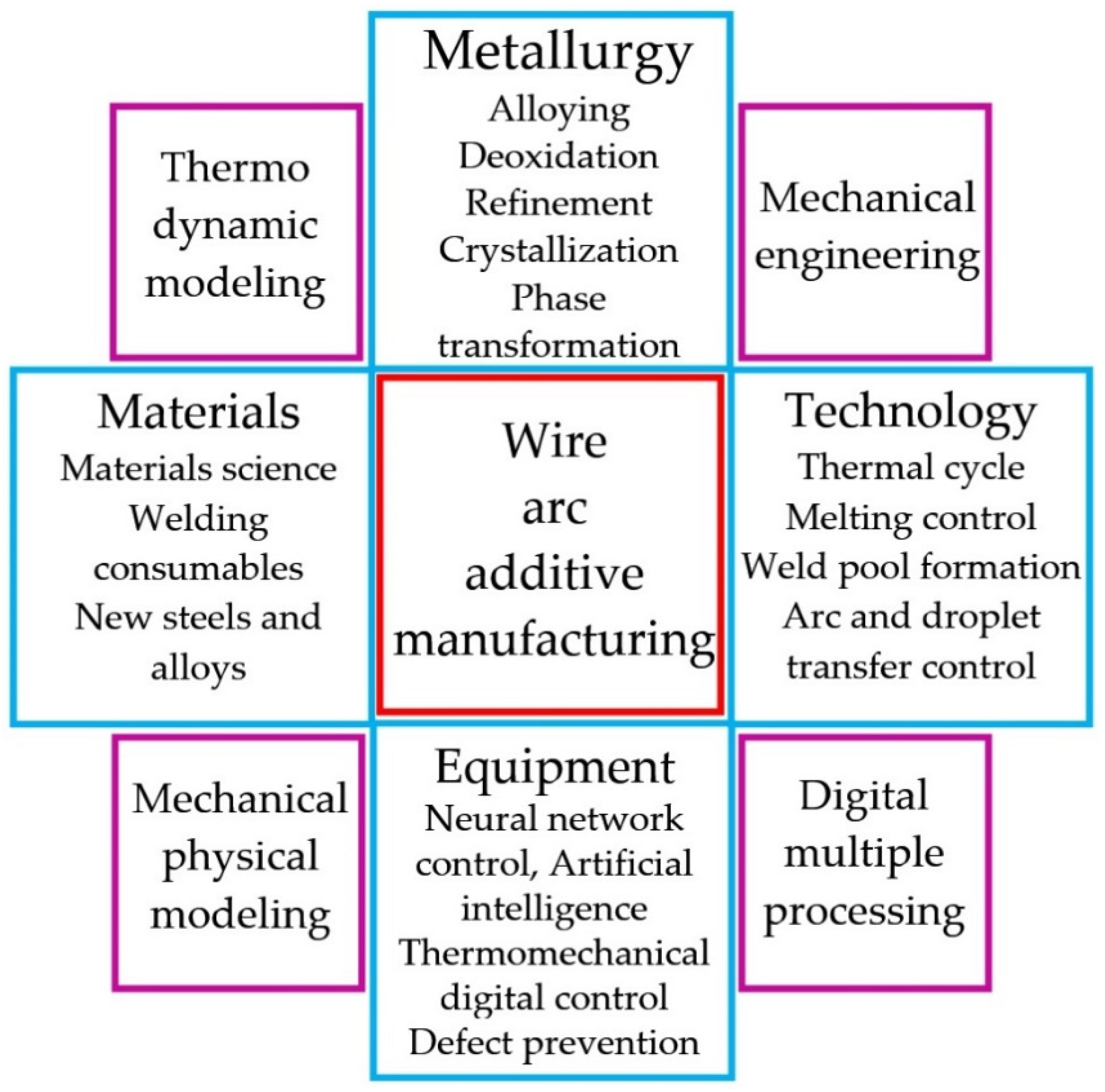
:1. Introduction
2. Materials and Methods
3. Results
4. Conclusions
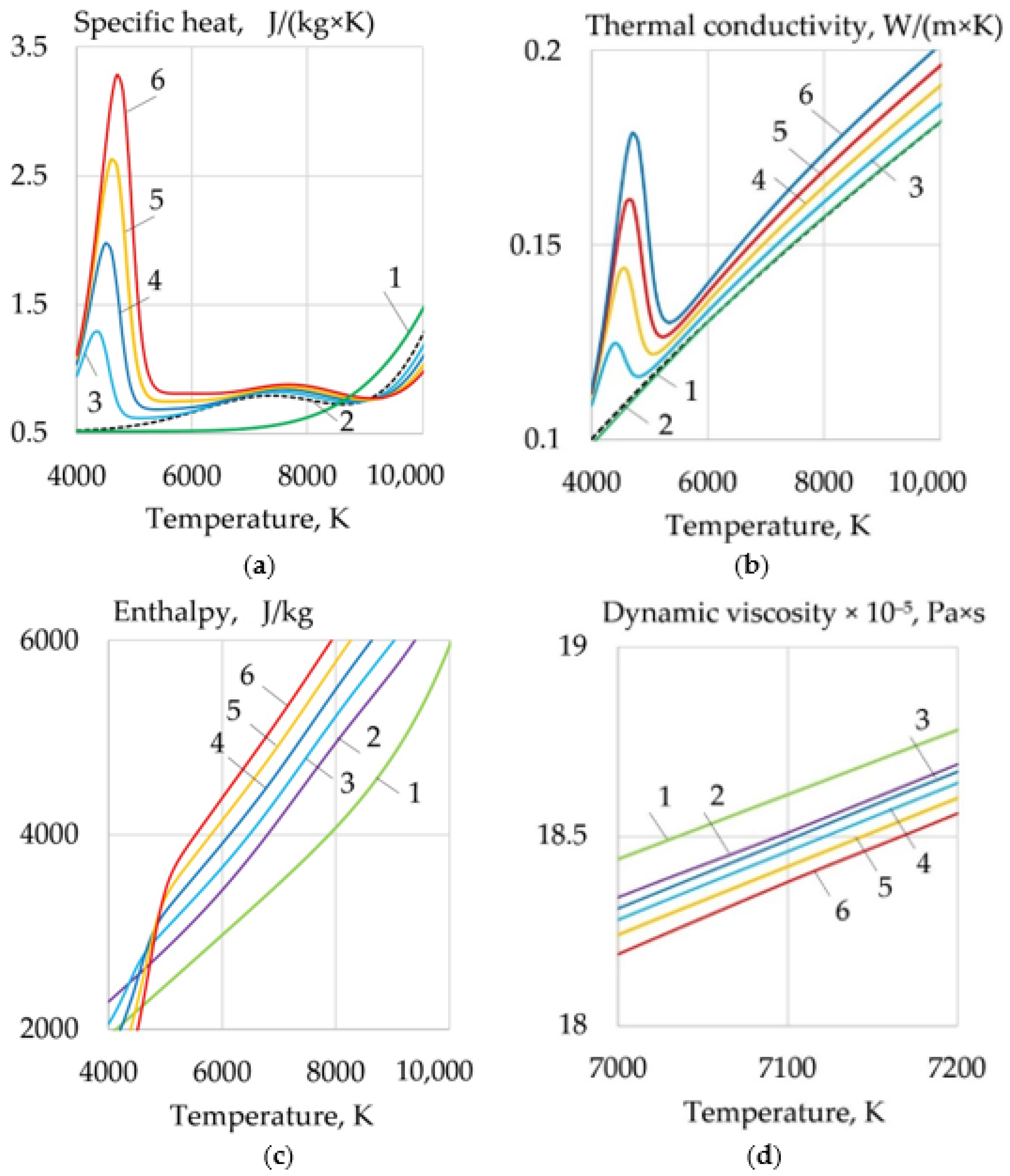
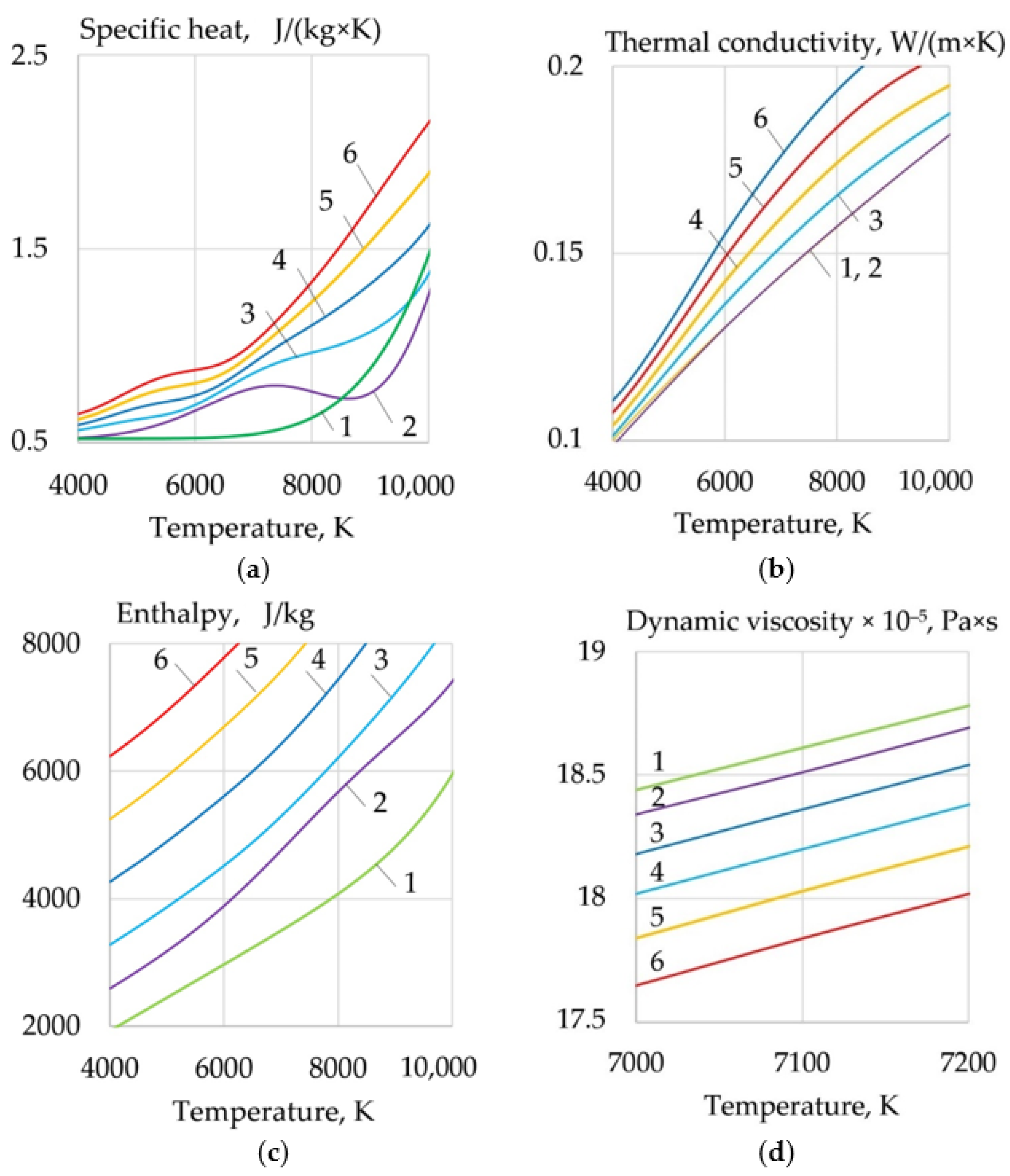
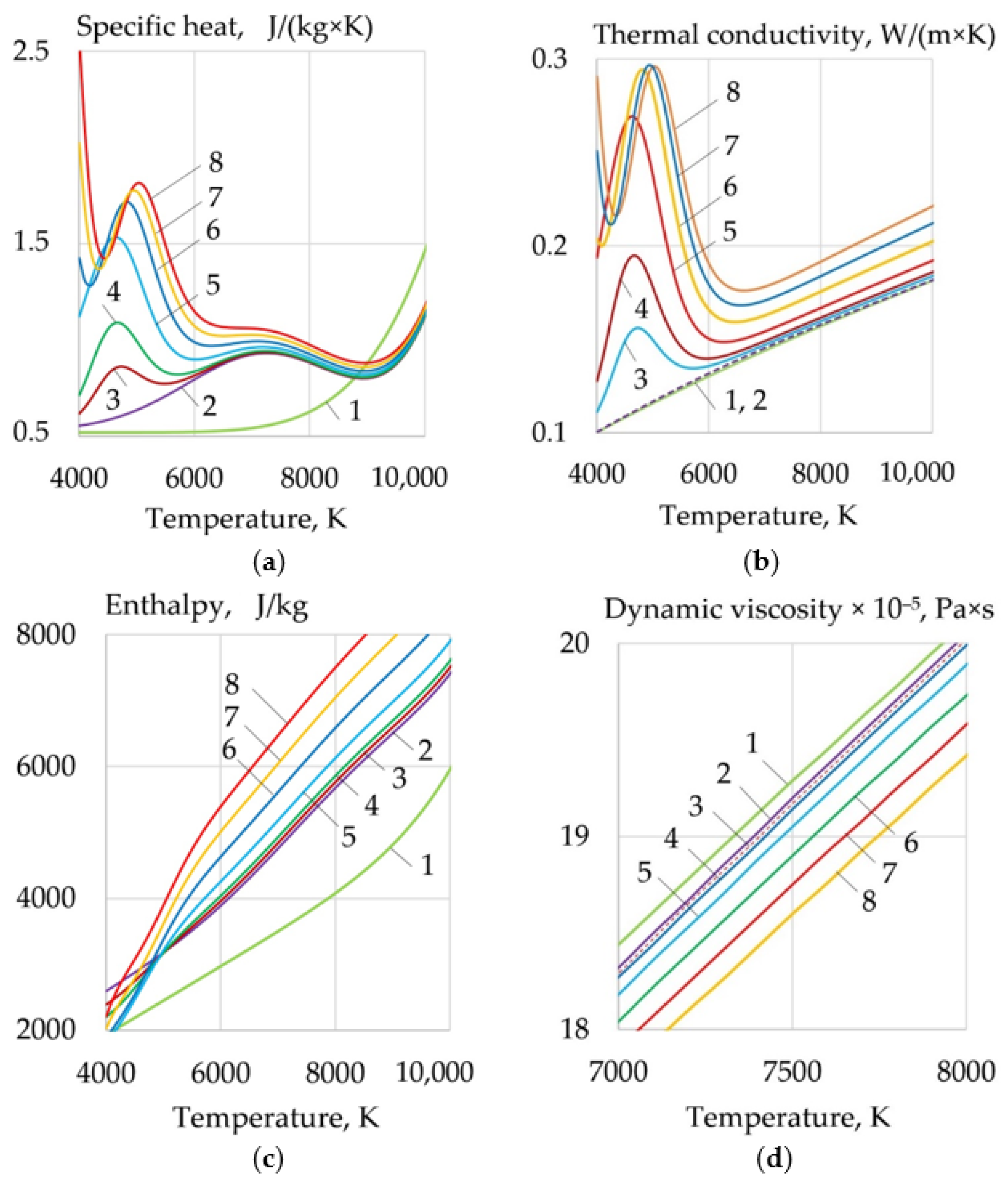
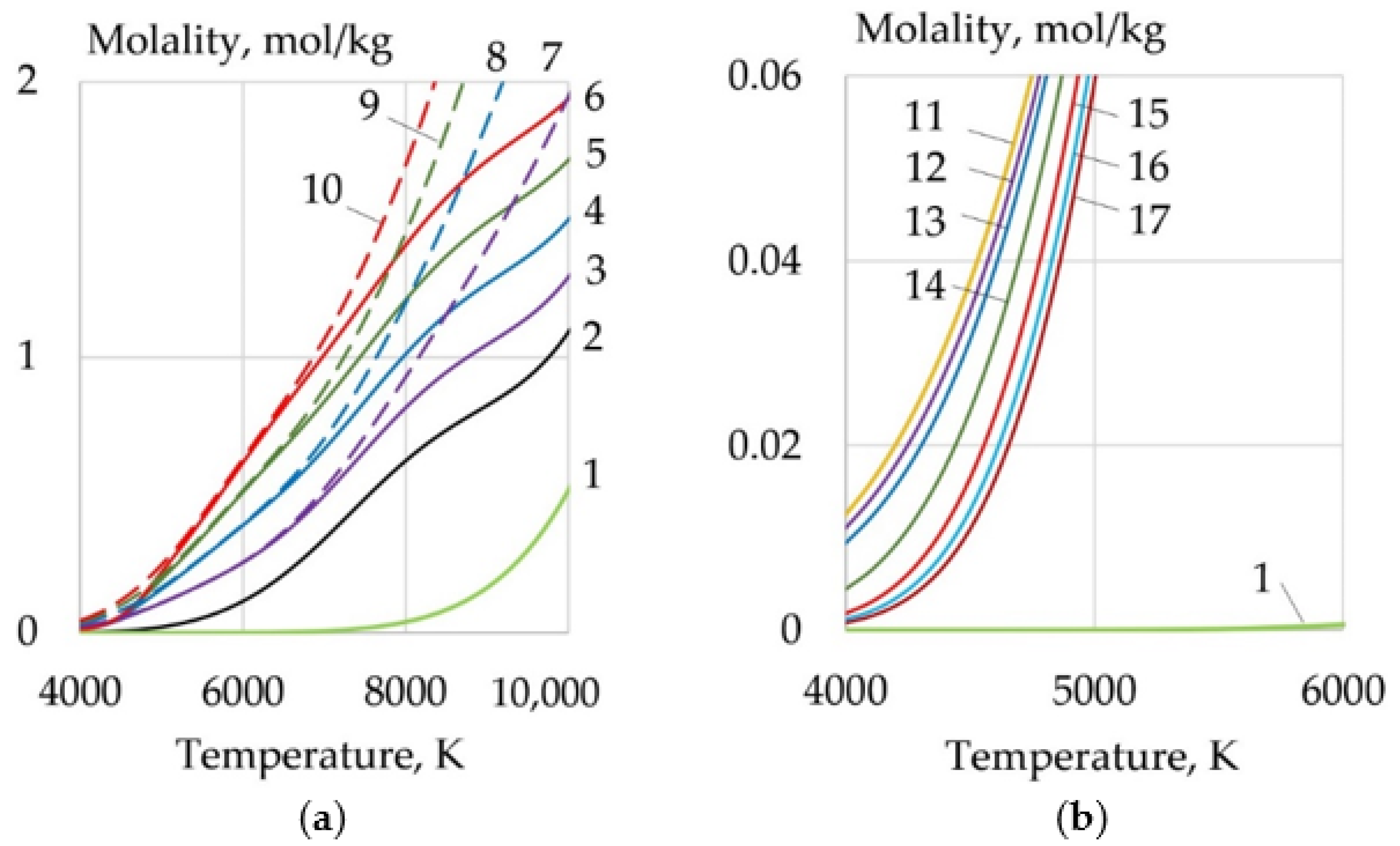
- For WAAM developed composite wires with a Ni-LaF3, Ni-LaB6 coating, the addition of LaF3, LaB6, and SF6 forms a molecular layer at the arc boundary at a temperature of 1000–6000 K, in which endothermic dissociation and ionization reactions take place. Under the influence of concentration and ambipolar diffusion, atoms, ions, and electrons are distributed in the longitudinal and transverse directions over the volume of the plasma, depending on the ionization energy and the atomic weight of the elements. Saturation of plasma with products of dissociation and ionization increases the specific heat, thermal conductivity, enthalpy, degree of ionization, and decreases the dynamic viscosity of the plasma. The change of the thermophysical properties of the plasma and the increase in the electron concentration led to an increase in the transfer of heat from the arc plasma to the surface of the wire.
- When LaF3 is added at 4000–6000 K, the specific heat of the plasma increases from 0.5 to 3.3 J/(kg × K), the thermal conductivity increases from 0.1 to 0.18 W/(m × K), and the enthalpy grows from 2000 to 4000 J/kg, the electron concentration increases from 1 to 2 mol/kg at 10,000 K. When LaB6 is added at 8000–10,000 K, the specific heat increases from 0.6 to 2.2 J/(kg × K), thermal conductivity grows from 0.16 to 0.22 W/(m × K), enthalpy increases from 6000 to 13000 J/kg, electron concentration grows from 1 to 4 mol/kg. When SF6 is added at 4000–6000 K, the specific heat increases from 0.5 to 2.5 J/(kg × K), the thermal conductivity increases from 0.1 to 0.3 W/(m × K), the enthalpy grows from 6000 to 9000 J/kg at 10,000 K, the electron concentration decreases from 0.06 to 0.02 mol/kg.
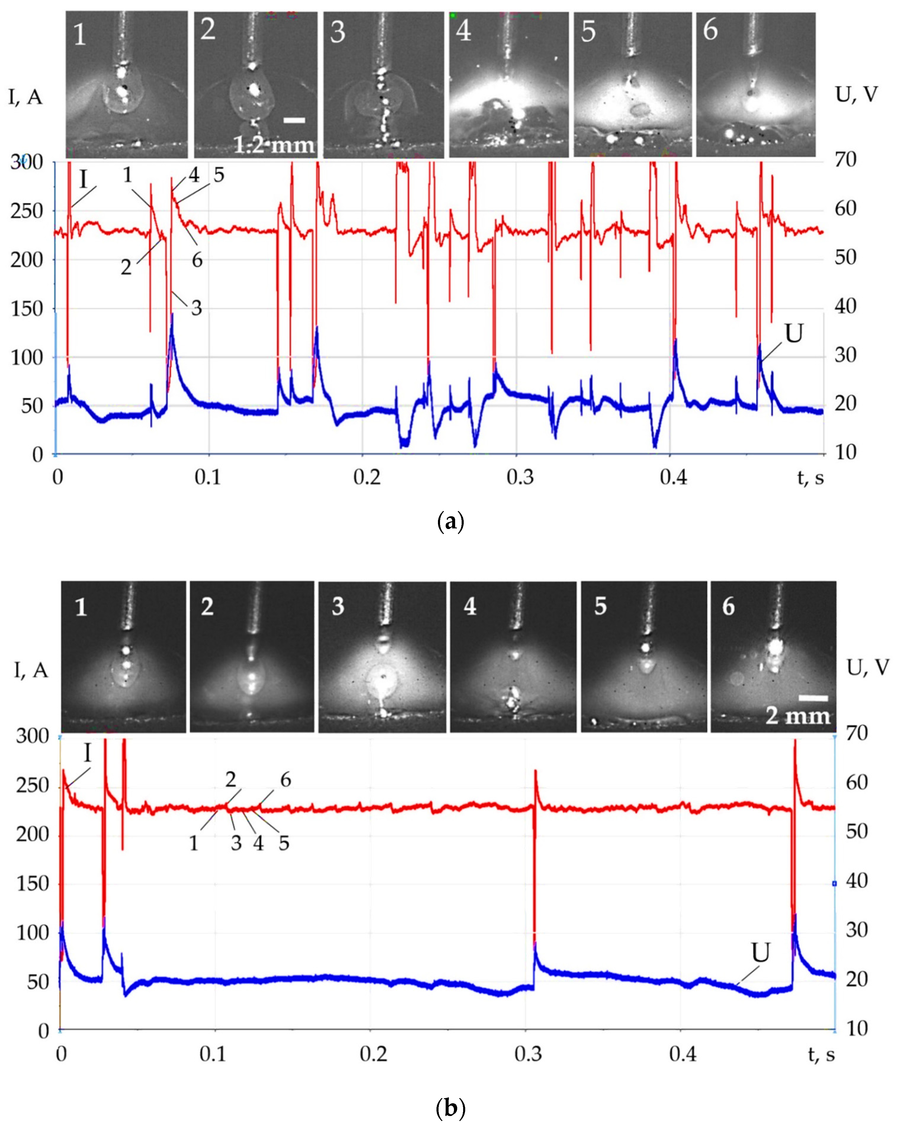
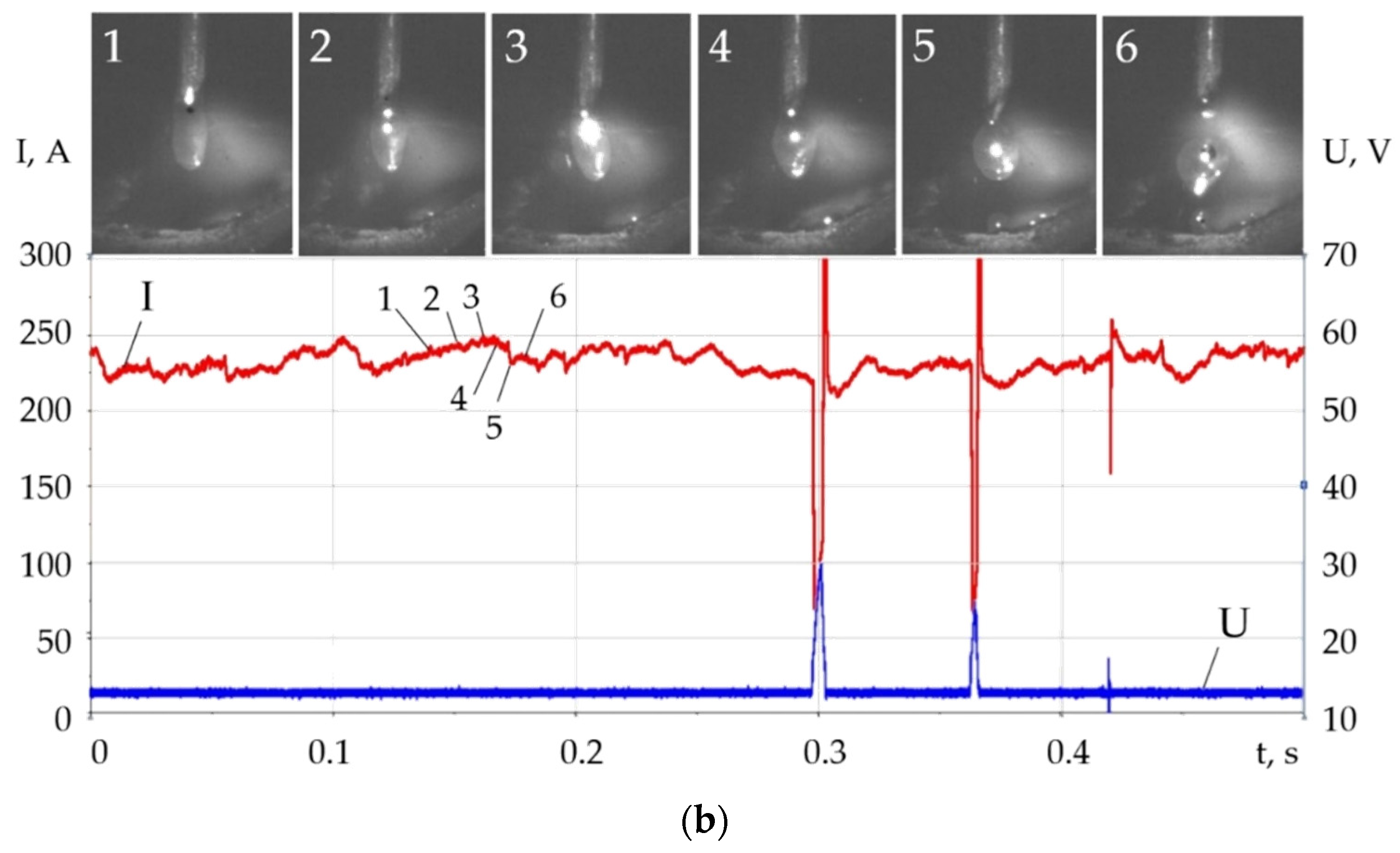
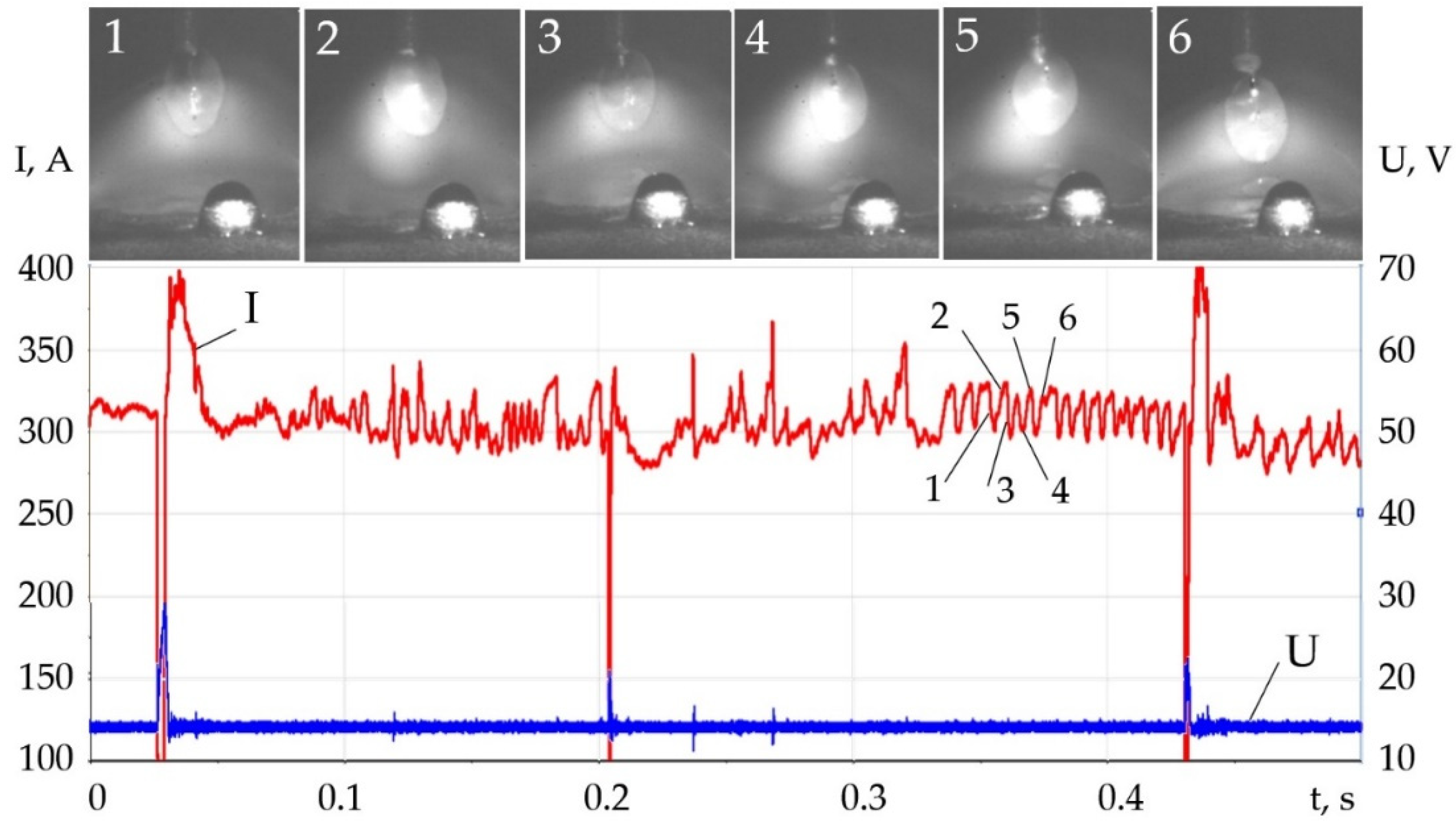
- Changes in the thermophysical properties of plasma with the addition of LaF3, LaB6, and SF6 improved ionization, increased heat transfer from the plasma to the anode and surface adsorption of La, B, and S are the reasons for the change in the balance of forces acting during the droplet transfer. The greatest effect is observed in the growth of the Lorentz electromagnetic force, since there is an increase in the concentration of electrons. Experimentally, this is confirmed by an increase in the welding current up to 7–21%. Another effect is a decrease in the surface tension force with an increase in the droplet temperature and surface adsorption of La, B, S.
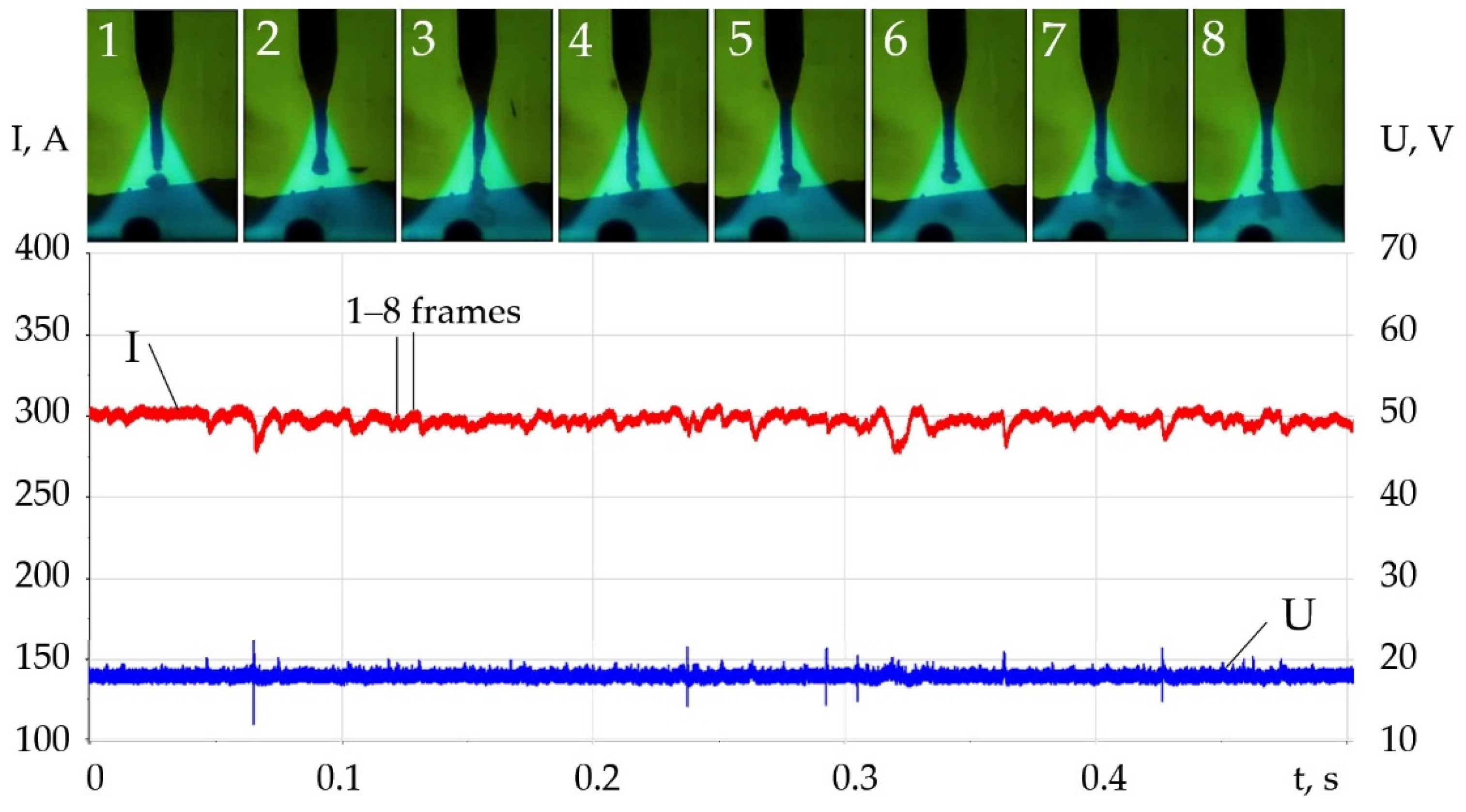
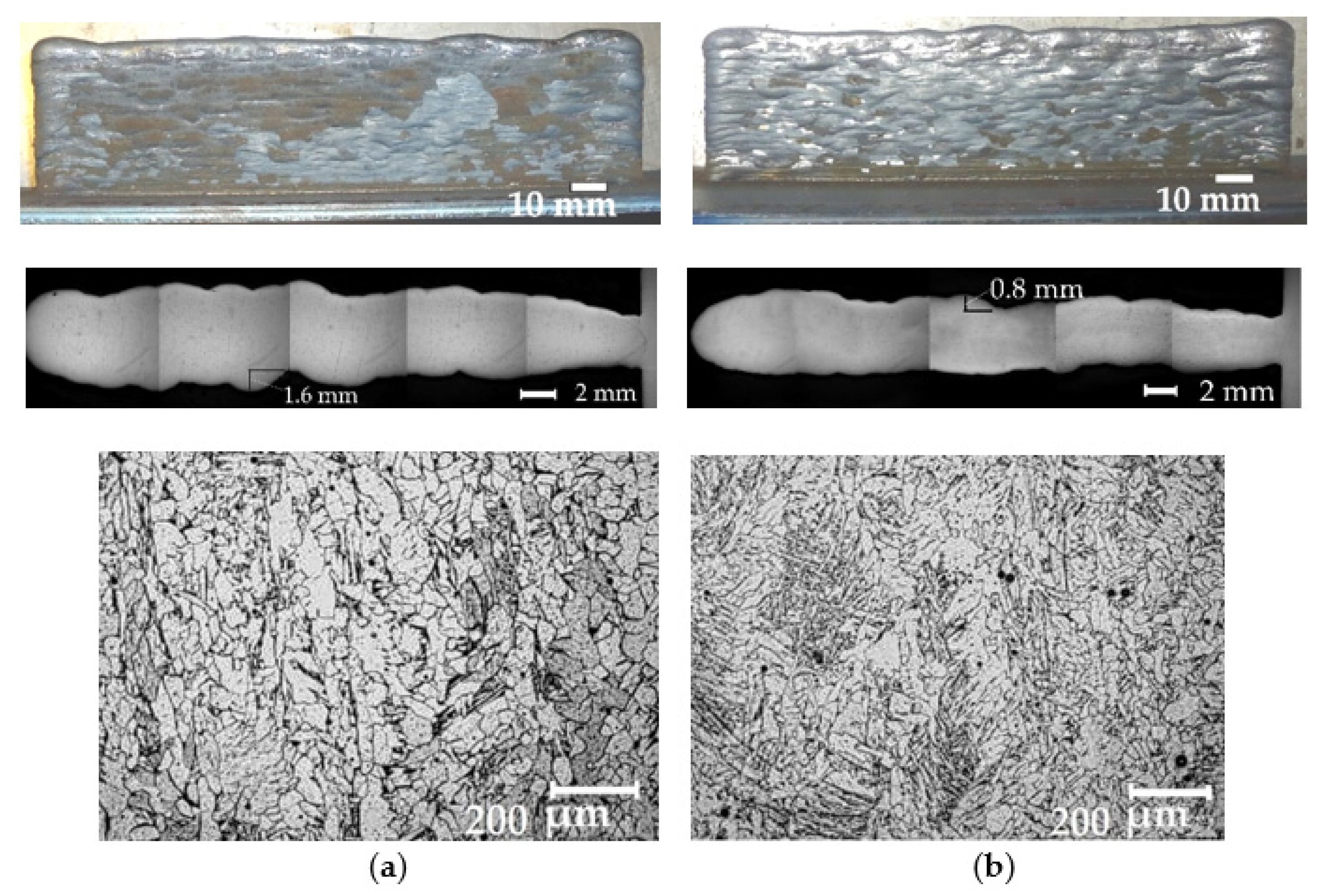
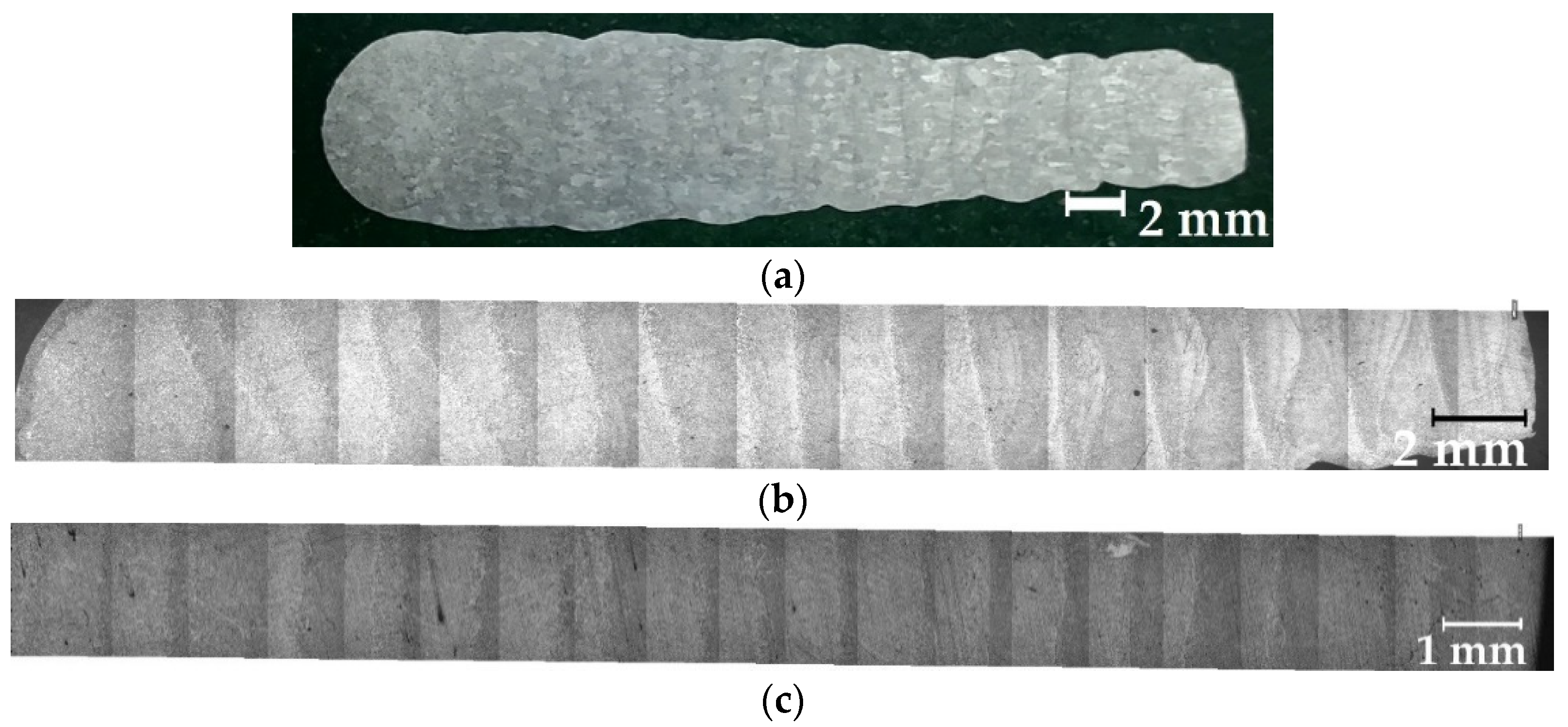
- The change in the balance of forces during melting of the wire, the increase in the Lorentz electromagnetic force, and the decrease in the surface tension force led to the decrease in the diameter of the droplets and improved droplet transfer. The balance of forces should take into account the normal reactive force and the tangential force of the Marangoni effect, which requires a further study. With the addition of LaF3 during melting of the G3Si1 wire, the droplet diameter decreased from 2.5 to 2 mm, the frequency of short circuits decreased from 40 to 4 Hz. The addition of LaB6 and 3.2 wt.% SF6 when melting the 316L wire reduced the droplet diameter from 2.6 to 1–1.2 mm without short circuits. When melting the AlMg5Mn1Ti wire, the addition of SF6 to 6.4 wt.% reduced the droplet diameter from 3.0 to 1.5 mm.
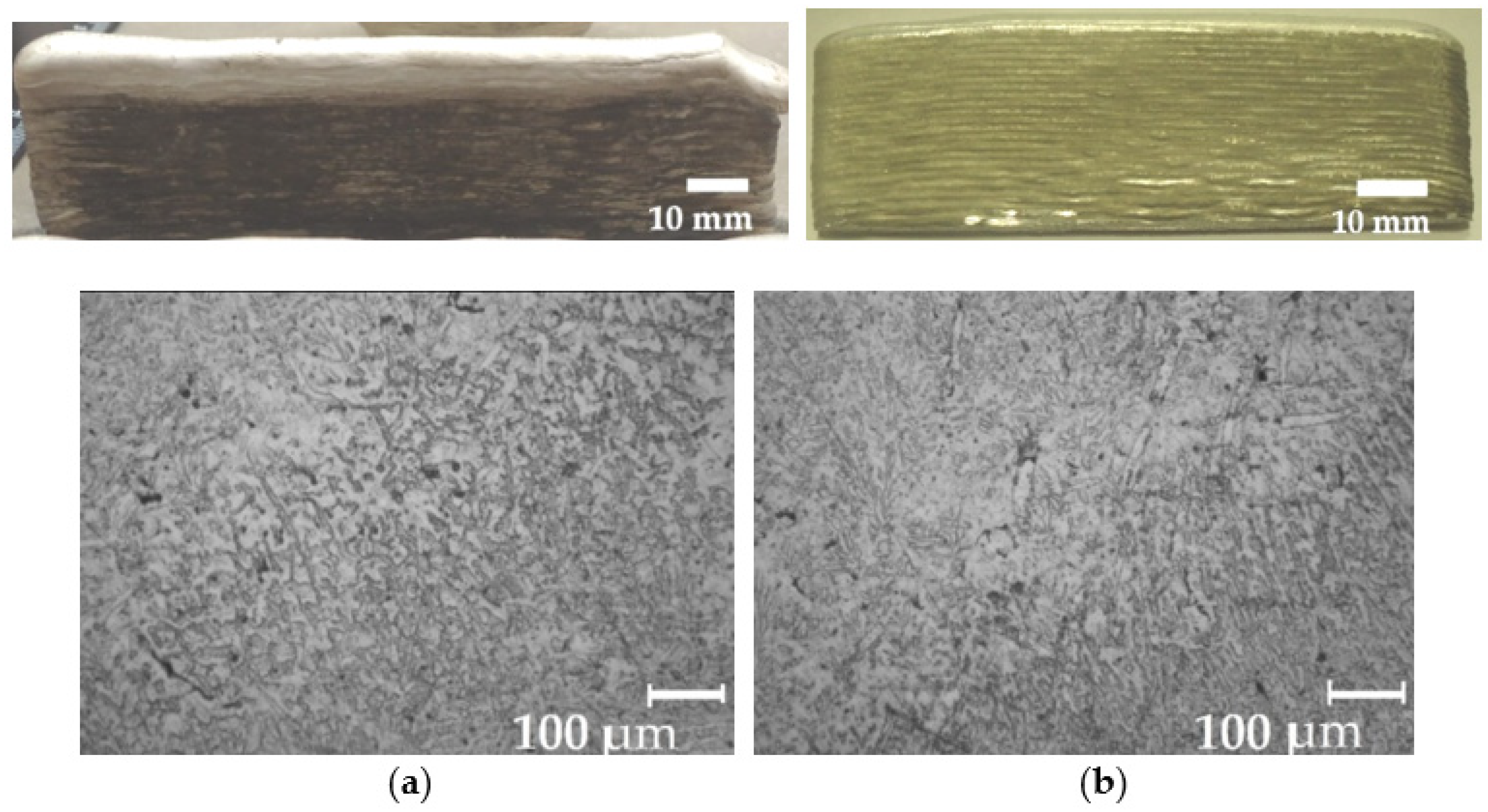
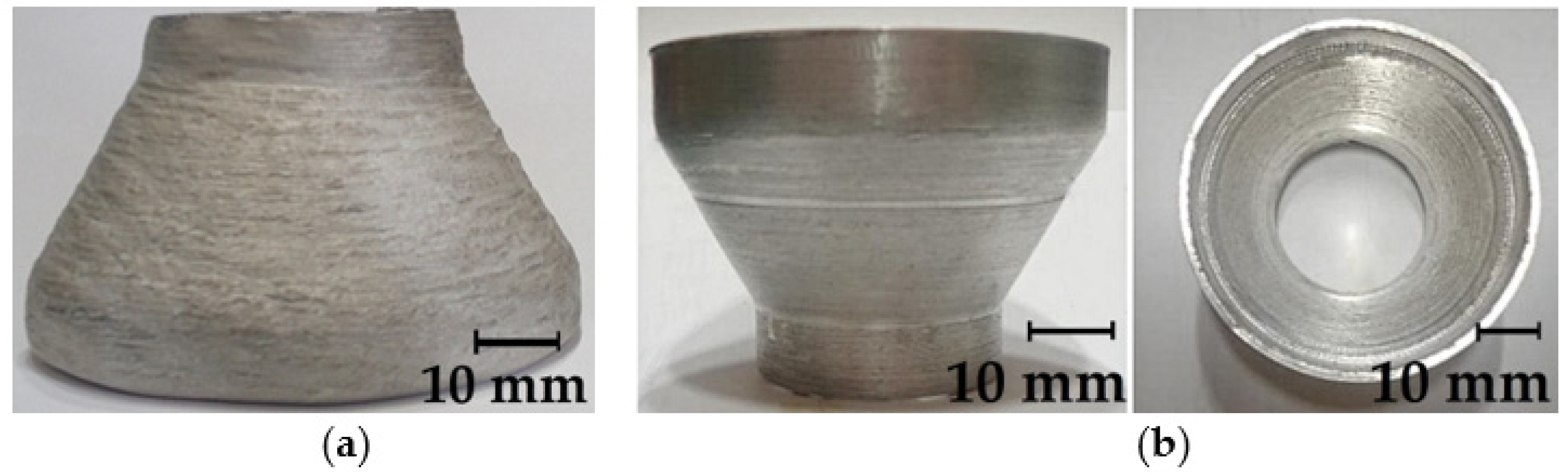
- The change of the thermophysical properties of plasma and droplet transfer during melting of wires with the addition of LaF3, LaB6, and SF6 made the WAAM technologically effective for manufacturing products of complex shape using G3Si1, 316L, AlMg5Mn1Ti, and CuCr0.7 wires. This effect increased the accuracy of the geometry of products by two times, reduced the thickness of the deposited metal layer by 1.25–2 times, and refined the microstructure of the deposited metal, which indicates that the goal of the study has been achieved.
Author Contributions
Funding
Institutional Review Board Statement
Informed Consent Statement
Data Availability Statement
Conflicts of Interest
References
- Rodrigues, T.A.; Duarte, V.; Miranda, R.M.; Santos, T.G.; Oliveira, J.P. Current Status and Perspectives on Wire and Arc Additive Manufacturing (WAAM). Materials 2019, 12, 1121. [Google Scholar] [CrossRef] [PubMed] [Green Version]
- Jin, W.; Zhang, C.; Jin, S.; Tian, Y.; Wellmann, D.; Liu, W. Wire Arc Additive Manufacturing of Stainless Steels: A Review. Appl. Sci. 2020, 10, 1563. [Google Scholar] [CrossRef] [Green Version]
- Wu, B.; Pan, Z.; Ding, D.; Cuiuri, D.; Li, H.; Xu, J.; Norrish, J. A Review of the Wire Arc Additive Manufacturing of Metals: Properties, Defects and Quality Improvement. J. Manuf. Process. 2018, 35, 127–139. [Google Scholar] [CrossRef]
- Elmer, J.W.; Vaja, J.; Carpenter, J.S.; Coughlin, D.R.; Dvornak, M.J.; Hochanadel, P.; Gurung, P.; Johnson, A.; Gibbs, G. Wire-Based Additive Manufacturing of Stainless Steel Components. Weld. J. 2020, 99, 8–24. [Google Scholar] [CrossRef]
- Posch, G.; Chladi, K.; Chladil, H. Material Properties of CMT—Metal Additive Manufactured Duplex Stainless Steel Blade-Like Geometries. Weld. World 2017, 61, 873–882. [Google Scholar] [CrossRef]
- Huynh, L.; Rotella, J.; Sangid, M.D. Fatigue Behavior of IN718 Microtrusses Produced via Additive Manufacturing. Mater. Des. 2016, 105, 278–289. [Google Scholar] [CrossRef]
- Zhai, Y.; Galarraga, H.; Lados, D.A. Microstructure, Static Properties, and Fatigue Crack Growth Mechanisms in Ti-6Al-4V Fabricated by Additive Manufacturing: LENS and EBM. Eng. Fail. Anal. 2016, 69, 3–14. [Google Scholar] [CrossRef]
- Baby, J.; Amirthalingam, M. Microstructural Development During Wire Arc Additive Manufacturing of Copper-Based Components. Weld. World 2020, 64, 395–405. [Google Scholar] [CrossRef]
- Shakil, S.I.; Dharmendra, C.; Amirkhiz, B.S.; Verma, D.; Mohammadi, M.; Haghshenas, M. Micromechanical Characterization of Wire-Arc Additive Manufactured and Cast Nickel Aluminum Bronze: Ambient and Intermediate Temperatures. Mater. Sci. Eng. A 2020, 792, 139773. [Google Scholar] [CrossRef]
- Gierth, M.; Henckell, P.; Ali, Y.; Scholl, J.; Bergmann, J.P. Wire Arc Additive Manufacturing (WAAM) of Aluminum Alloy AlMg5Mn with Energy-Reduced Gas Metal Arc Welding (GMAW). Materials 2020, 13, 2671. [Google Scholar] [CrossRef]
- Köhler, M.; Fiebig, S.; Hensel, J.; Dilger, K. Wire and Arc Additive Manufacturing of Aluminum Components. Metals 2019, 9, 608. [Google Scholar] [CrossRef] [Green Version]
- Silva, C.M.A.; Braganca, I.M.F.; Cabrita, A.; Quintino, L.; Martins, P.A.F. Formability of a Wire Arc Deposited Aluminium Alloy. J. Braz. Soc. Mech. Sci. Eng. 2017, 39, 4059–4068. [Google Scholar] [CrossRef]
- Ge, J.; Ma, T.; Chen, Y.; Jin, T.; Fu, H.; Xiao, R.; Lei, Y.; Lin, J. Wire-Arc Additive Manufacturing H13 Part: 3D Pore Distribution, Microstructural Evolution, and Mechanical Performances. J. Alloys Compd. 2019, 783, 145–155. [Google Scholar] [CrossRef]
- Seow, C.E.; Coules, H.E.; Wu, G.; Khan, R.H.U.; Xu, X.; Williams, S. Wire + Arc Additively Manufactured Inconel 718: Effect of Post-Deposition Heat Treatments on Microstructure and Tensile Properties. Mater. Des. 2019, 183, 108157. [Google Scholar] [CrossRef]
- Cong, B.; Ding, L.; Williams, S. Effect of Arc Mode in Cold Metal Transfer Process on Porosity of Additively Manufactured Al-6.3%Cu Alloy. Int. J. Adv. Manuf. Technol. 2015, 76, 1593–1606. [Google Scholar] [CrossRef]
- Haden, C.V.; Zeng, G.; Carter, F.M., III; Ruhl, C.; Krick, B.A.; Harlow, D.G. Wire and Arc Additive Manufactured Steel: Tensile and Wear Properties. Addit. Manuf. 2017, 16, 115–123. [Google Scholar] [CrossRef]
- Stützer, J.; Totzauer, T.; Wittig, B.; Zinke, M.; Jüttner, S. GMAW Cold Wire Technology for Adjusting the Ferrite—Austenite Ratio of Wire and Arc Additive Manufactured Duplex Stainless Steel Components. Metals 2019, 9, 564. [Google Scholar] [CrossRef] [Green Version]
- Müller, J.; Grabowski, M.; Müller, C.; Hensel, J.; Unglaub, J.; Thiele, K.; Kloft, H.; Dilger, K. Design and Parameter Identification of Wire and Arc Additively Manufactured (WAAM) Steel Bars for Use in Construction. Metals 2019, 9, 725. [Google Scholar] [CrossRef] [Green Version]
- Ding, J.; Colegrove, P.; Mehnen, J.; Ganguly, S.; Almeida, P.S.; Wang, F.; Williams, S. Thermo-Mechanical Analysis of Wire and Arc Additive Layer Manufacturing Process on Large Multi-Layer Parts. Comput. Mater. Sci. 2011, 50, 3315–3322. [Google Scholar] [CrossRef] [Green Version]
- Dahat, S.; Hurtig, K.; Andersson, J.; Scotti, A. A Methodology to Parameterize Wire + Arc Additive Manufacturing: A Case Study for Wall Quality Analysis. J. Manuf. Mater. Process. 2020, 4, 14. [Google Scholar] [CrossRef] [Green Version]
- Lee, S.H. CMT-Based Wire Arc Additive Manufacturing Using 316L Stainless Steel: Effect of Heat Accumulation on the Multi-Layer Deposits. Metals 2020, 10, 278. [Google Scholar] [CrossRef] [Green Version]
- Rodrigues, T.A.; Duarte, V.; Avila, J.A.; Santos, T.G.; Miranda, R.M.; Oliveira, J.P. Wire and Arc Additive Manufacturing of HSLA Steel: Effect of Thermal Cycles on Microstructure and Mechanical Properties. Addit. Manuf. 2019, 27, 440–450. [Google Scholar] [CrossRef]
- Hosseini, V.A.; Högström, M.; Hurtig, K.; Bermejo, M.A.V.; Stridh, L.-E.; Karlsson, L. Wire-Arc Additive Manufacturing of a Duplex Stainless Steel: Thermal Cycle Analysis and Microstructure Characterization. Weld. World 2019, 63, 975–987. [Google Scholar] [CrossRef] [Green Version]
- Xia, C.; Pan, Z.; Polden, J.; Li, H.; Xu, Y.; Chen, S.; Zhang, Y. A Review on Wire Arc Additive Manufacturing: Monitoring, Control and a Framework of Automated System. J. Manuf. Syst. 2020, 57, 31–45. [Google Scholar] [CrossRef]
- Mirapeix, J.; Cobo, A.; Fuentes, J.; Davila, M.; Etayo, J.M.; Lopez-Higuera, J.-M. Use of the Plasma Spectrum RMS Signal for Arc-Welding Diagnostics. Sensors 2009, 9, 5263–5276. [Google Scholar] [CrossRef] [PubMed] [Green Version]
- Panda, B.; Shankhwar, K.; Garg, A.; Savalani, M.M. Evaluation of Genetic Programming-Based Models for Simulating Bead Dimensions in Wire and Arc Additive Manufacturing. J. Intell. Manuf. 2019, 30, 809–820. [Google Scholar] [CrossRef]
- Parshin, S.G. Metallurgy of Welding; Politech-Press: Saint-Petersburg, Russia, 2020; pp. 71–144. (In Russian) [Google Scholar]
- Sames, W.J.; List, F.A.; Pannala, S.; Dehoff, R.R.; Babu, S.S. The Metallurgy and Processing Science of Metal Additive Manufacturing. Int. Mater. Rev. 2016, 61, 315–360. [Google Scholar] [CrossRef]
- Wittig, B.; Zinke, M.; Jüttner, S. Influence of Arc Energy and Filler Metal Composition on the Microstructure in Wire Arc Additive Manufacturing of Duplex Stainless Steels. Weld. World 2021, 65, 47–56. [Google Scholar] [CrossRef]
- Asala, G.; Khan, A.K.; Andersson, J.; Ojo, O.A. Microstructural Analyses of ATI 718Plus Produced by Wire-Arc Additive Manufacturing Process. Metall. Mater. Trans. A 2017, 48, 4211–4228. [Google Scholar] [CrossRef] [Green Version]
- Hertel, M.; Trautmann, M.; Jäckel, S.; Füssel, U. The Role of Metal Vapour in Gas Metal Arc Welding and Methods of Combined Experimental and Numerical Process Analysis. Plasma Chem. Plasma Process. 2017, 37, 48–54. [Google Scholar] [CrossRef]
- Wagner, R.; Siewert, E.; Schein, J.; Hussary, N.; Jaeckel, S. Shielding Gas Influence on Emissions in Arc Welding. Weld. World 2018, 62, 647–652. [Google Scholar] [CrossRef]
- Sumi, H.; Kataoka, T.; Kitani, Y. Application of Narrow Gap Welding Process with “J-STARTM Welding” to Shipbuilding and Construction. JFE Tech. Rep. 2015, 20, 112–117. [Google Scholar]
- Weglowski, M.S. Modeling and Analysis of the Arc Light Spectrum in GMAW. Weld. J. 2008, 87, 212–218. [Google Scholar]
- Wang, C.; Wu, Y.; Chen, Z.; Yang, F.; Feng, Y.; Rong, M.; Zhang, H.; Chunlin, W.; Yi, W.; Zhexin, C.; et al. Thermodynamic and Transport Properties of Real Air Plasma in Wide Range of Temperature and Pressure. Plasma Sci. Technol. 2016, 18, 732–739. [Google Scholar] [CrossRef]
- Kataoka, T.; Ikeda, R.; Ono, M.; Yasuda, K.; Hirata, Y. Effect of REM Addition of Wire on CO2 Gas Shielded Arc Phenomenon. Weld. Int. 2009, 23, 517–522. [Google Scholar] [CrossRef]
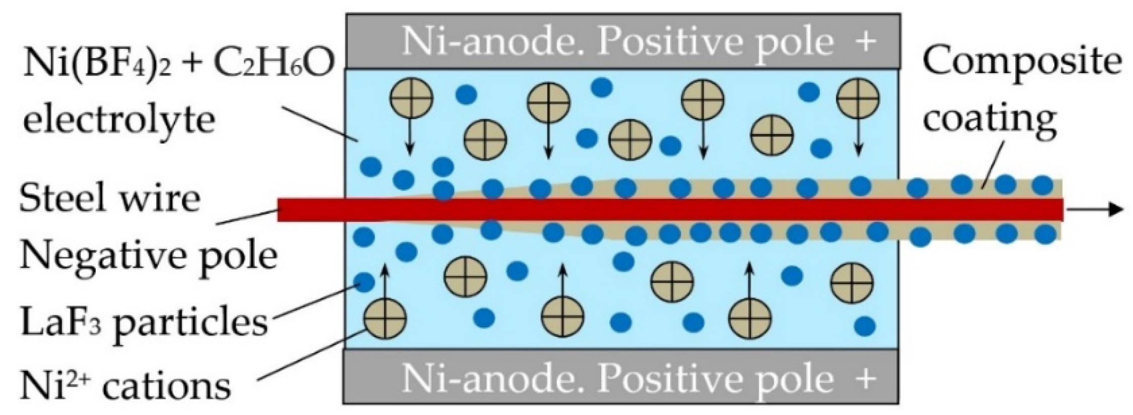
- Parshin, S.G.; Karkhin, V.A.; Mayr, P.; Maystro, A.S. The Effect of Electrochemical Composite Coatings with LaF3-LaB6 Particles in Nickel–Copper Matrix on the Metallurgical Processes in Arc Welding of Low Alloy Ferrite-Pearlite Steels. Materials 2021, 14, 1509. [Google Scholar] [CrossRef] [PubMed]
- Parshin, S.G. Metallurgical Effect of Rare-Earth Lanthanum Fluoride and Boride in the Composite Coating of Wires in the Arc Welding of Bainitic-Martensitic and Austenitic Steel. Metals 2020, 10, 1334. [Google Scholar] [CrossRef]
- Parshin, S.G.; Parshin, S.S.; Buerckner, H.; Semmler, W.; Kush, M.; Reinhardt, S.; Kuhn, S. Intensification of Melting of Wires in MIG/MAG Welding of Steels and Aluminium Alloys. Weld. Int. 2011, 25, 47–51. [Google Scholar] [CrossRef]
- Parshin, S.G. Using Ultrafine Particles of Activating Fluxes for Increasing the Productivity of MIG/MAG Welding of Steels. Weld. Int. 2012, 26, 800–804. [Google Scholar] [CrossRef]
- Parshin, S.G. Increasing the Productivity of MIG Welding Aluminium Alloys by Adding Ultrafine Particles of Activating Fluxes. Weld. Int. 2013, 27, 735–739. [Google Scholar] [CrossRef]
- Parshin, S.G. MAG Welding with Nanostructured Electrode Materials with Halide-Containing Coatings. Weld. Int. 2013, 27, 825–829. [Google Scholar] [CrossRef]
- Parshin, S.G. Effect of Gaseous Sulphur Hexafluoride SF6 on the Process of MIG Welding of AlMg4.5Mn0.7 Aluminium alloy. Weld. Int. 2016, 30, 1–5. [Google Scholar] [CrossRef]
- Parshin, S.G. MIG Welding of S235JR Steel with the Addition of Gaseous Sulphur Hexafluoride SF6 to Argon. Weld. Int. 2017, 31, 863–867. [Google Scholar] [CrossRef]
- Kim, Y.S.; Eager, T.W. Analysis of Metal Transfer in Gas Metal Arc Welding. Weld. J. 1993, 72, 269-s. [Google Scholar]
- Finkelnburg, W.; Maecker, H. Elektrische Bögen und thermisches Plasma. In Encyclopedia of Physics; Springer: Berlin/Heidelberg, Germany, 1956; Volume 22, pp. 254–444. (In Germany) [Google Scholar]
- Egry, I.; Ricci, E.; Novakovic, R.; Ozawa, S. Surface Tension of Liquid Metals and Alloys—Recent Developments. Adv. Colloid Interface Sci. 2010, 159, 198–212. [Google Scholar] [CrossRef]
- Sahoo, P.; Debroy, T.; McNallan, M.J. Surface Tension of Binary Metal—Surface Active Solute Systems under Conditions Relevant to Welding Metallurgy. Met. Mater. Trans. B 1988, 19, 483–491. [Google Scholar] [CrossRef]
- Keene, B.J. Review of Data for the Surface Tension of Iron and its Binary Alloys. Int. Mater. Rev. 1988, 33, 1–37. [Google Scholar] [CrossRef]
- Kasama, A.; McLean, A.; Miller, W.A.; Morita, Z.; Ward, M.J. Surface Tension of Liquid Iron and Iron-Oxygen Alloys. Can. Metall. Q. 1983, 22, 9–17. [Google Scholar] [CrossRef]
- Korobeinikov, I.; Chebykin, D.; Seetharaman, S.; Volkova, O. Effect of Boron Micro-alloying on the Surface Tension of Liquid Iron and Steel Alloys. Int. J. Thermophys. 2020, 41, 1–14. [Google Scholar] [CrossRef]
- Park, H.; Trautmann, M.; Tanaka, K.; Tanaka, V.; Murphy, A.B. A Computational Model of Gas Tungsten Arc Welding of Stainless Steel: The Importance of Considering the Different Metal Vapours Simultaneously. J. Phys. D Appl. Phys. 2018, 51, 395202. [Google Scholar] [CrossRef]
- Matsushita, T.; Belov, I.; Siafakas, D.; Jarfors, A.E.W.; Watanabe, M. Interfacial Phenomena between Molten Iron and Molten Slag—Effect of Nitrogen on the Marangoni Convection. J. Mater. Sci. 2021, 56, 7811–7822. [Google Scholar] [CrossRef]
- Waszink, J.Y.; Heuvel, G.L.P.M. Heat Generation and Heat Flow in the Filler Metal in GMA Welding. Weld. J. 1982, 8, 269–282. [Google Scholar]
- Karkhin, V.A. Thermal Processes in Welding; Springer: Singapore, 2019; pp. 381–390. [Google Scholar]
- Granovsky, V.L. Electrical Current in Gas. Stationary Current; Nauka: Moscow, Russia, 1971; pp. 117–127. (In Russian) [Google Scholar]
- Khrabry, A.; Kaganovich, I.D.; Nemchinsky, V.; Khodak, A. Investigation of the Short Argon Arc with Hot Anode. II. Analytical Model. Phys. Plasmas 2018, 25, 013522. [Google Scholar] [CrossRef] [Green Version]
- Boulos, M.I.; Fauchais, P.L.; Pfender, E. Thermodynamic Properties of Plasmas. In Handbook of Thermal Plasmas; Springer: Cham, Switzerland, 2020; pp. 1–46. [Google Scholar]
- Maher, I.; Boulos, M.I.; Pierre, L.; Pfender, E. Plasma Radiation Transport. In Handbook of Thermal Plasmas; Springer: Cham, Switzerland, 2020; pp. 1–74. [Google Scholar]
- Murphy, A.B.; Tanaka, M.; Yamamoto, K.; Tashiro, S.; Sato, T.; Lowke, J.J. Modelling of Thermal Plasmas for Arc Welding: The Role of the Shielding Gas Properties and of Metal Vapour. J. Phys. D Appl. Phys. 2009, 42, 194006. [Google Scholar] [CrossRef]


| Wire | C | Mn | Si | Mo | Cr | Ni | S | P | Others |
|---|---|---|---|---|---|---|---|---|---|
| G3Si1 1.2 mm | 0.06–0.14 | 1.4–1.6 | 0.8–1 | – | – | – | <0.025 | <0.025 | <97.2 Fe |
| 316L 1.0 mm | <0.03 | <2 | <0.075 | 2–3 | 16–18 | 10–14 | <0.03 | <0.045 | <64.82 Fe |
| AlMg5Mn1Ti 1.6 mm | – | 0.5–1 | <0.25 | – | 0.05–0.2 | – | – | – | <98.55 Al |
| CuCr0.7 1.6 mm | – | – | – | – | 0.4–1 | <0.01 | <0.01 | <0.005 | <98.9 Cu |
| Wire | Current, A | Voltage, V | Wire Feed Rate, m/min |
|---|---|---|---|
| G3Si1 1.2 mm | 221 | 19 | 5 |
| 316L 1.0 mm | 215 | 13 | 5 |
| AlMg5Mn1Ti 1.6 mm | 140 | 20 | 6 |
| Wire | Current, A | Voltage, V | Wire Feed Rate, m/min | Travel Speed, m/min |
|---|---|---|---|---|
| G3Si1 1.2 mm | 98 | 14.6 | 2.1 | 0.6 |
| 316L 1.0 mm | 64 | 12.9 | 2.3 | 0.4 |
| AlMg5Mn1Ti 1.6 mm | 110 | 15 | 3.0 | 0.8 |
| CuCr0.7 1.6 mm | 130 | 14.5 | 3.2 | 0.8 |
Publisher’s Note: MDPI stays neutral with regard to jurisdictional claims in published maps and institutional affiliations. |
© 2021 by the authors. Licensee MDPI, Basel, Switzerland. This article is an open access article distributed under the terms and conditions of the Creative Commons Attribution (CC BY) license (https://creativecommons.org/licenses/by/4.0/).
Share and Cite
Parshin, S.G.; Mayr, P. Thermophysical Properties of Electric Arc Plasma and the Wire Melting Effect with Lanthanum and Sulfur Fluorides Addition in Wire Arc Additive Manufacturing. Metals 2021, 11, 1756. https://doi.org/10.3390/met11111756
Parshin SG, Mayr P. Thermophysical Properties of Electric Arc Plasma and the Wire Melting Effect with Lanthanum and Sulfur Fluorides Addition in Wire Arc Additive Manufacturing. Metals. 2021; 11(11):1756. https://doi.org/10.3390/met11111756
Chicago/Turabian StyleParshin, Sergey G., and Peter Mayr. 2021. "Thermophysical Properties of Electric Arc Plasma and the Wire Melting Effect with Lanthanum and Sulfur Fluorides Addition in Wire Arc Additive Manufacturing" Metals 11, no. 11: 1756. https://doi.org/10.3390/met11111756
APA StyleParshin, S. G., & Mayr, P. (2021). Thermophysical Properties of Electric Arc Plasma and the Wire Melting Effect with Lanthanum and Sulfur Fluorides Addition in Wire Arc Additive Manufacturing. Metals, 11(11), 1756. https://doi.org/10.3390/met11111756