
Experimental Investigation of Pressure Drop Performance of Smooth and Dimpled Single Plate-Fin Heat Exchangers


Abstract
:1. Introduction
2. Experimental Study
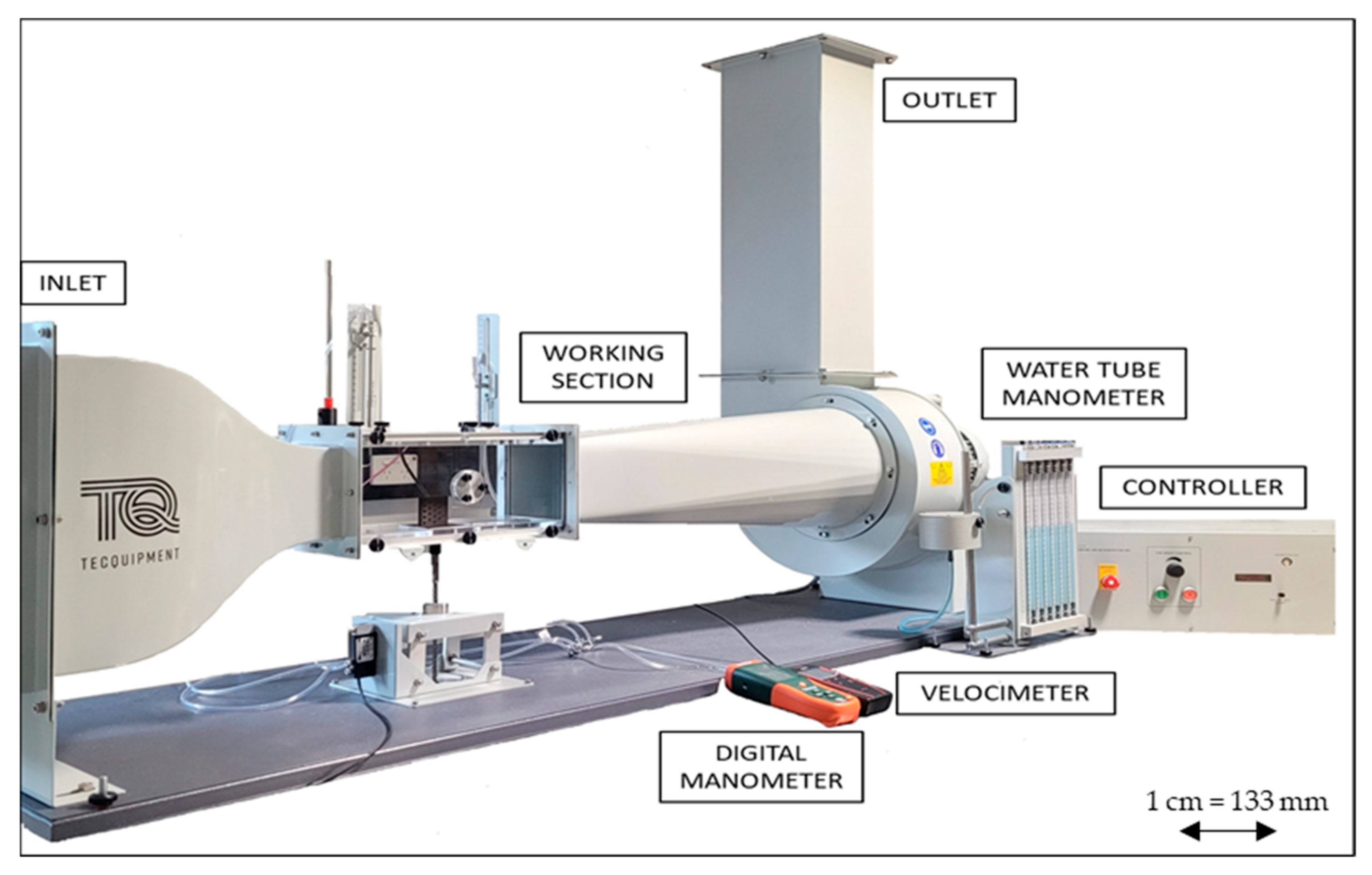
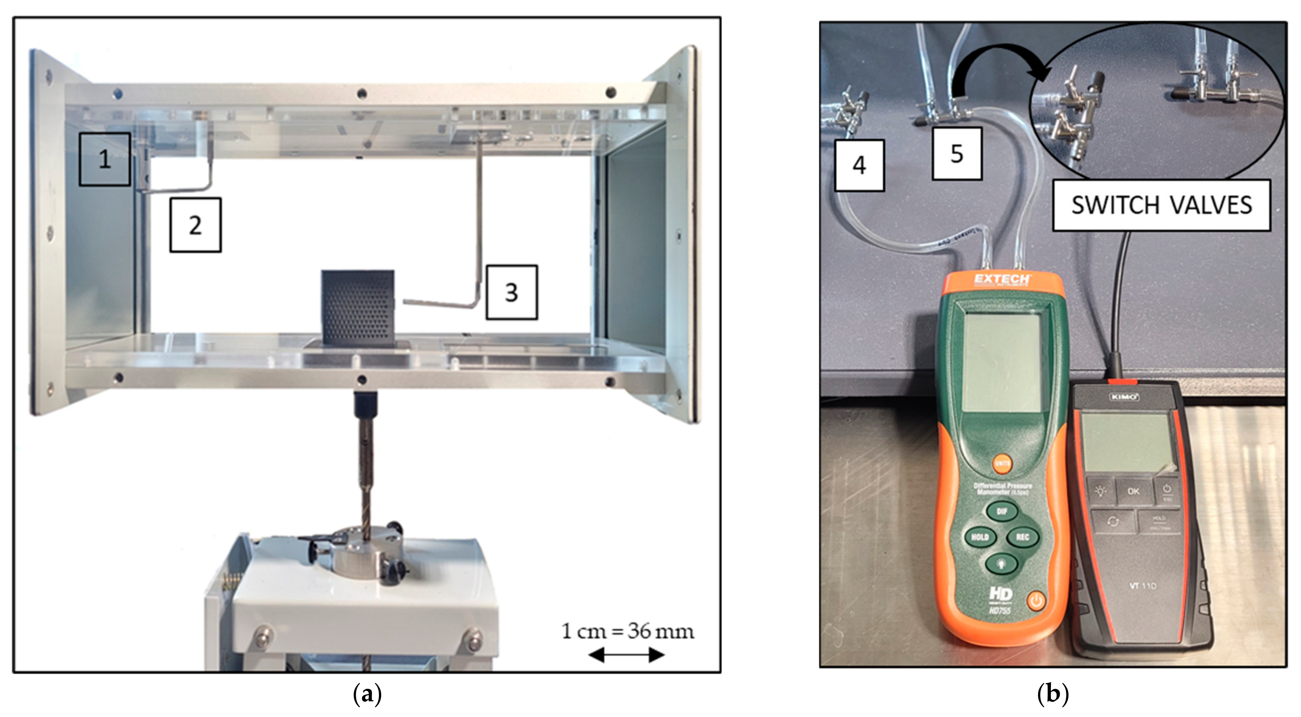
2.1. Experimental Setup
2.2. Pressure Performance Criteria
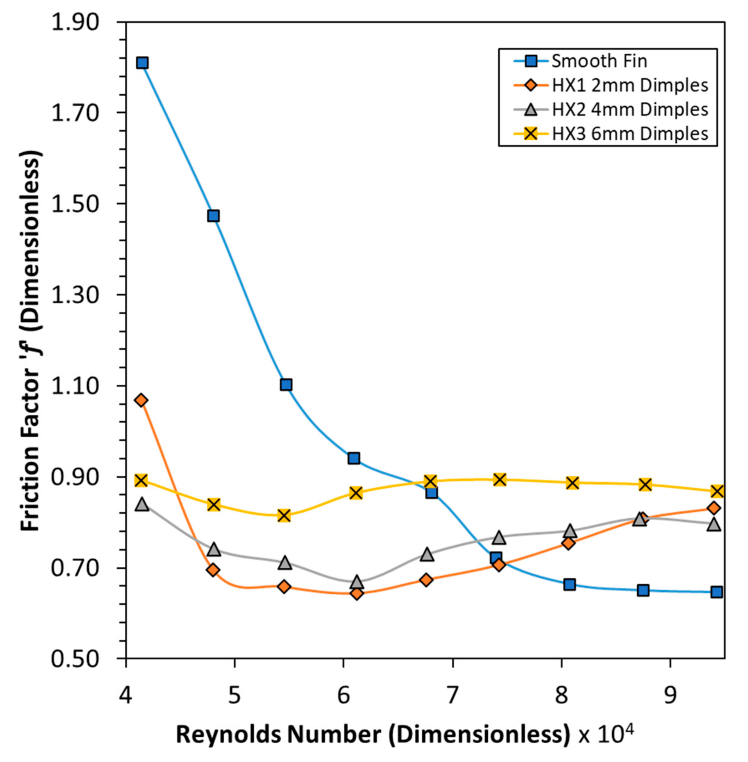
2.2.1. Friction Factor
2.2.2. Reynolds Number
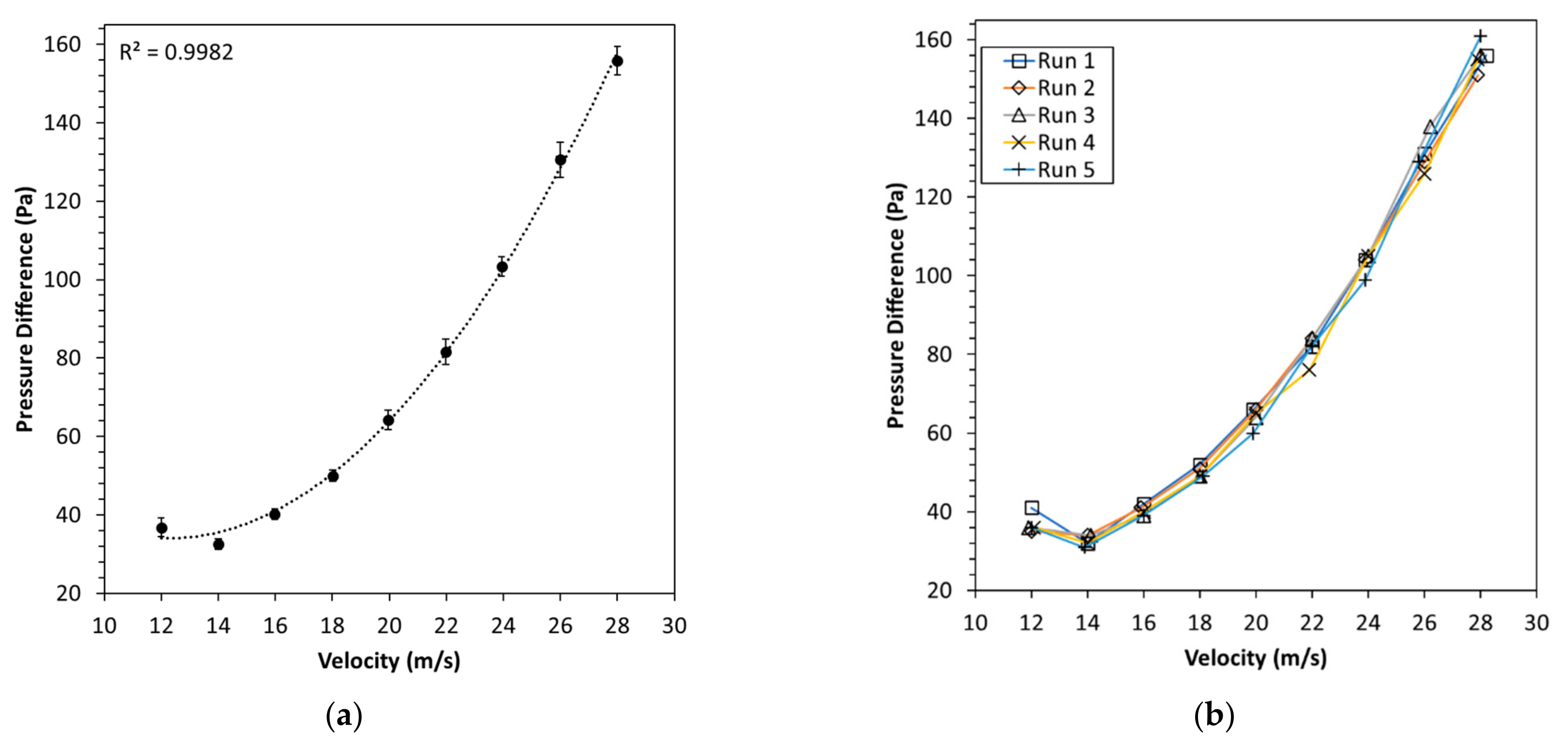
2.3. Uncertainty
2.4. Test Methodology
2.5. Test Parameters
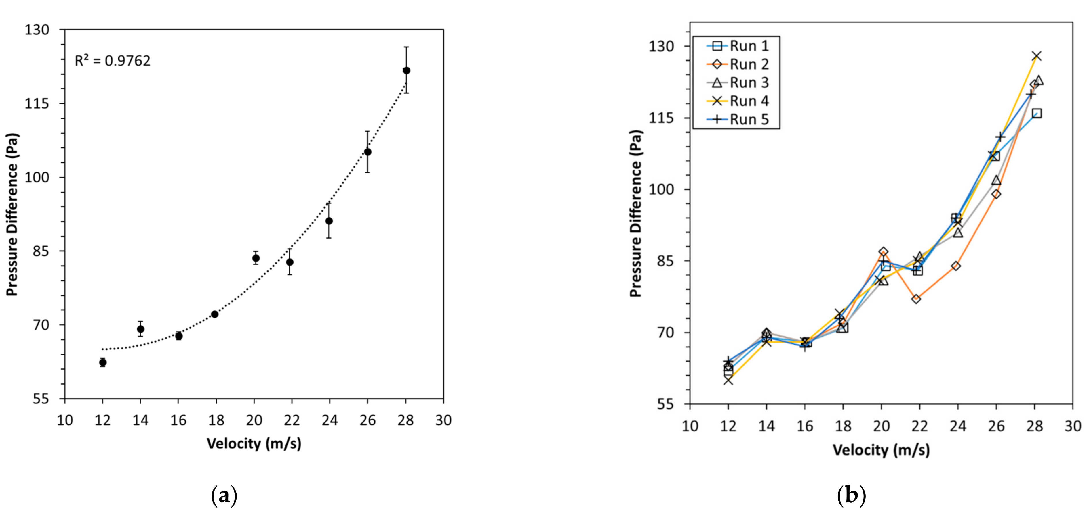
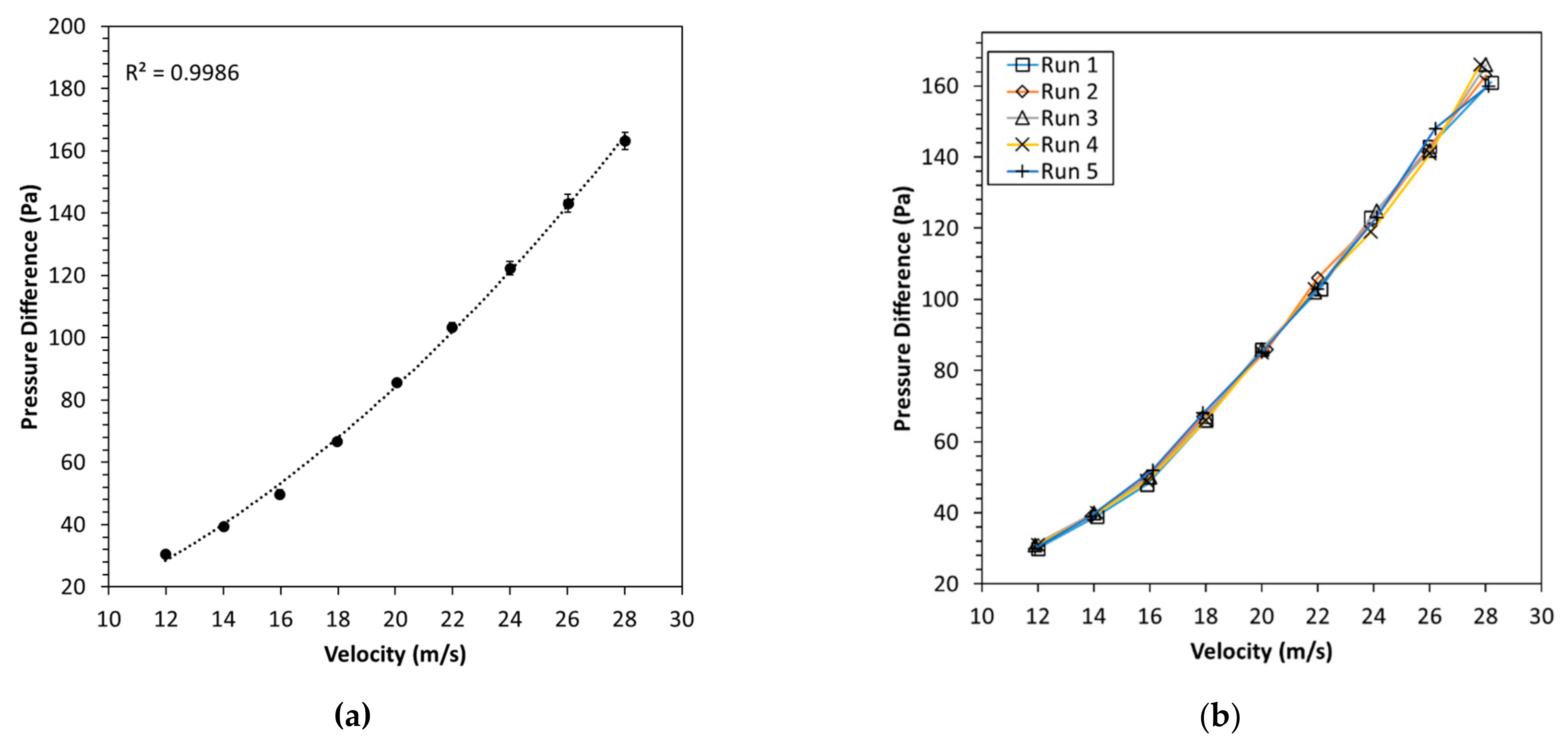
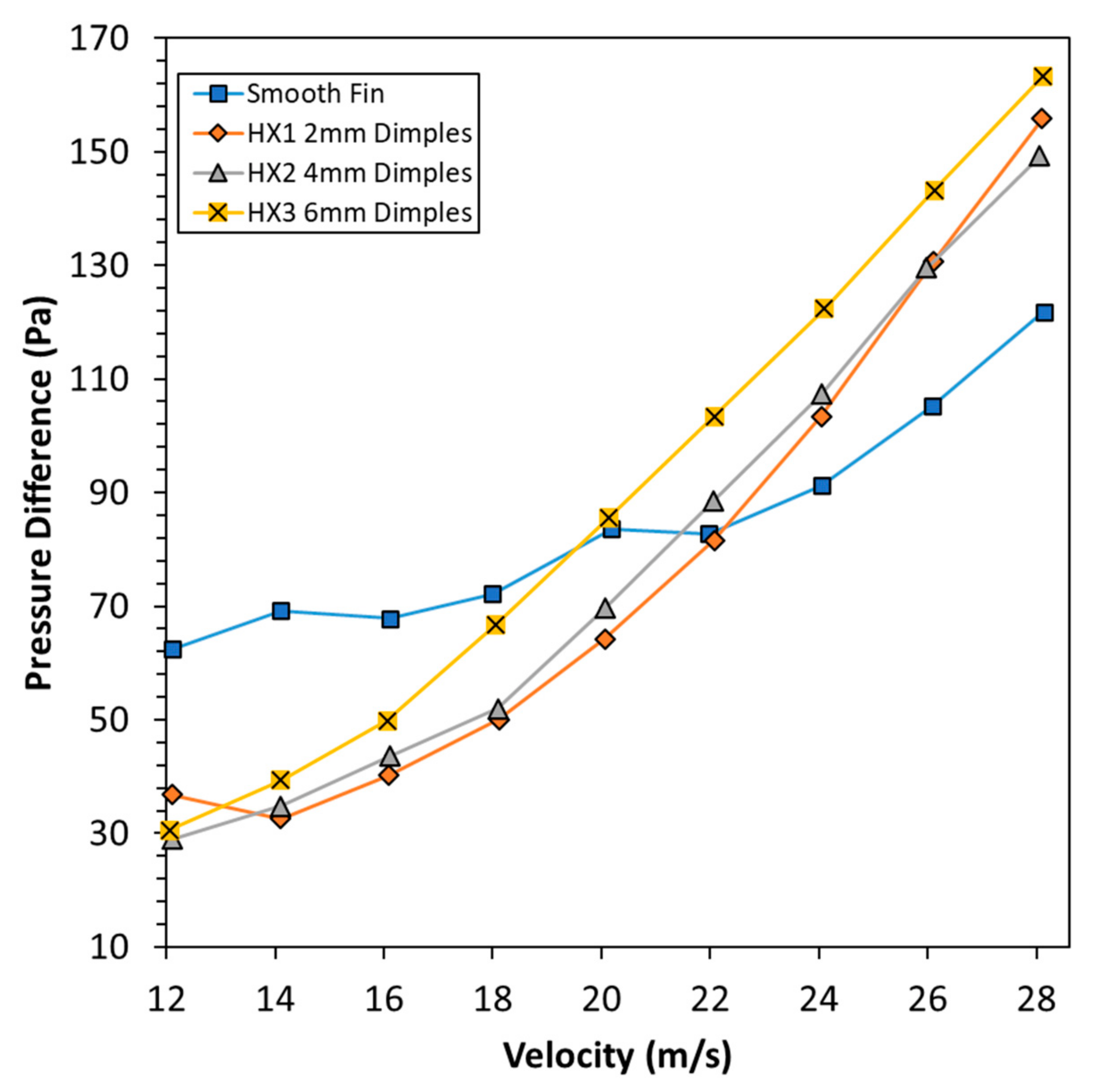
3. Results
4. Discussion of Results
5. Conclusions
Future Work
- Heat transfer studies should be conducted on the geometries investigated in the current study. Even though a significant pressure drop reduction was observed with the introduction of dimples, how well these dimples allowed the transfer of heat will eventually be a decisive factor in the relevance of the use of additive manufacturing and the use of turbulators in improving the efficiency of HXs.
- Mathematical models should be investigated that allow the design of dimples based on common parameters observed in the application of HXs. These include velocity, drag, Reynolds number, surface roughness and other factors that contribute to increasing the pressure drop efficiency of HXs. The current literature regarding dimples has mainly focused on experimental results, where the design of the dimples is either chosen arbitrarily based on existing literature or is influenced by their existing applications in golf balls. These designs have been verified for their effectiveness based on these experimental parameters. A framework or a mathematical model that provides insight into the design of dimple parameters, such as the optimal depth and diameter for specific velocities or specialised applications, will be highly advantageous in removing the need for extensive testing of various arbitrarily chosen dimple designs.
Author Contributions
Funding
Institutional Review Board Statement
Informed Consent Statement
Data Availability Statement
Acknowledgments
Conflicts of Interest
References
- Thulukkanam, K. Heat Exchanger Design Handbook; Taylor & Francis Group: Boca Raton, FL, USA, 2013. [Google Scholar]
- Shah, R.K.; Sekulic, D.P. Fundamentals of Heat Exchanger Design; John Wiley & Sons: Hoboken, NJ, USA, 2003. [Google Scholar]
- Li, Q.; Flamant, G.; Yuan, X.; Neveu, P.; Luo, L. Compact heat exchangers: A review and future applications for a new generation of high temperature solar receivers. Renew. Sustain. Energy Rev. 2011, 15, 4855–4875. [Google Scholar] [CrossRef]
- Hesselgreaves, J.E.; Law, R.; Reay, D.A. Compact Heat Exchangers; Elsevier: Oxford, UK, 2017. [Google Scholar]
- Oliveira, J.P.; LaLonde, A.; Ma, J. Processing parameters in laser powder bed fusion metal additive manufacturing. Mater. Des. 2020, 193, 108762. [Google Scholar] [CrossRef]
- Wong, M.; Owen, I.; Sutcliffe, C.J.; Puri, A. Convective heat transfer and pressure losses across novel heat sinks fabricated by selective laser melting. Int. J. Heat Mass Transf. 2009, 52, 281–288. [Google Scholar] [CrossRef]
- Dede, E.M.; Joshi, S.N.; Zhou, F. Topology Optimization, Additive Layer Manufacturing, and Experimental Testing of an Air-Cooled Heat Sink. J. Mech. Des. 2015, 137, 111403. [Google Scholar] [CrossRef]
- McDonough, J.R. A perspective on the current and future roles of additive manufacturing in process engineering, with an emphasis on heat transfer. Therm. Sci. Eng. Prog. 2020, 19, 100594. [Google Scholar] [CrossRef]
- Vafadar, A.; Guzzomi, F.; Rassau, A.; Hayward, K. Advances in Metal Additive Manufacturing: A Review of Common Processes, Industrial Applications, and Current Challenges. Appl. Sci. 2021, 11, 1213. [Google Scholar] [CrossRef]
- Frazier, W.E. Metal Additive Manufacturing: A Review. J. Mater. Eng. Perform. 2014, 23, 1917–1928. [Google Scholar] [CrossRef]
- Sheikholeslami, M.; Ganji, D.D. Nanofluid Forced Convection Heat Transfer. In Applications of Nanofluid for Heat Transfer Enhancement; Elsevier: Amsterdam, The Netherlands, 2017; pp. 127–193. [Google Scholar]
- Alam, T.; Kim, M.H. A comprehensive review on single phase heat transfer enhancement techniques in heat exchanger applications. Renew. Sustain. Energy Rev. 2018, 81, 813–839. [Google Scholar] [CrossRef]
- Burgess, N.; Ligrani, P. Effects of dimple depth on channel nusselt numbers and friction factors. J. Heat Transf. 2005, 127, 839–847. [Google Scholar] [CrossRef]
- Rao, Y.; Wan, C.; Xu, Y. An experimental study of pressure loss and heat trasnfer in the pin fin-dimple channels with various dimple depths. Int. J. Heat Mass Transf. 2012, 55, 6723–6733. [Google Scholar] [CrossRef]
- van Nesselrooij, M.; Veldhuis, L.L.M.; van Oudheusden, B.W.; Schrijer, F.F.J. Drag reduction by means of dimpled surfaces in turbulent boundary layers. Exp. Fluids 2016, 57, 142. [Google Scholar] [CrossRef]
- Rao, Y.; Li, B.; Feng, Y. Heat transfer of turbulent flow over surfaces with spherical dimples and teardrop dimples. Exp. Therm. Fluid Sci. 2015, 61, 201–209. [Google Scholar] [CrossRef]
- Moon, H.; O’Connell, T.; Glezer, B. Channel height effect on heat transfer and friction in a dimple passage. J. Eng. Gas Turbines Power 2000, 122, 307–313. [Google Scholar] [CrossRef]
- Abbas, Z.; Shah, S.I.A.; Javed, A.; Jami, M.L. Influence of dimple design on aerodynamic drag of Golf balls. In Proceedings of the 2019 Sixth International Conference on Aerospace Science and Engineering (ICASE), Islamabad, Pakistan, 12–14 November 2019. [Google Scholar]
- Zhong, X.; Shuzhao, L.; Xiaoyan, W.; Xijiang, Z. Research on Drag Reduction Effect of Concave Non-smooth Surface in Air. Adv. Mater. Res. 2011, 299–300, 7–11. [Google Scholar]
- Yan, F.; Yang, H.; Wang, L. Study of the Drag Reduction Characteristics of Circular Cylinder with Dimpled Surface. Water 2021, 13, 197. [Google Scholar] [CrossRef]
- Shaughnessy, E.J.; Katz, I.M.; Schaffer, J.P. 8.4 Static, Dynamic, Stagnation and Total Pressure. In Introduction to Fluid Mechanics; Oxfor University Press: New York, NY, USA, 2005; pp. 490–491. [Google Scholar]
- Barker, G. The Engineer’s Guide to Plant Layout and Piping Design for the Oil and Gas Industries; Gulf Professional Publishing: Burlington, MA, USA, 2018. [Google Scholar]
- Genium Publishing Corporation. 402.1—Guidelines for the Use of Data in Section 402. In Fluid Flow—Data Book; Genium Publishing Corporation: New York, NY, USA, 1993; p. 5. [Google Scholar]
- Layton, W. 5.4 The Reynolds Number. In Introduction to the Numerical Analysis of Incompressible Viscous Flows; Society for Industrial and Applied Mathematics: Philadelphia, PA, USA, 2008; pp. 83–86. [Google Scholar]
- Vafadar, A.; Guzzomi, F.G.; Hayward, K. Experimental Investigation and Comparison of the Thermal Performance of Additively and Conventionally Manufactured Heat Exchangers. Metals 2021, 11, 574. [Google Scholar] [CrossRef]
- Çengel, Y.A.; Cimbala, J.M. Chapter 10—Approximate Solutions of the Navier-Stokes Equations: Turbulent Flat Plate Boundary Layer. In Fluid Mechanics: Fundamentals and Applications; McGraw-Hill Higher Education: New York, NY, USA, 2017; p. 1117. [Google Scholar]
- Ting, L.L. Effects of Dimple Size and Depth on Golf Ball Aerodynamic Performance. In Proceedings of the ASME/JSME 2003 4th Joint Fluids Summer Engineering Conference, Honolulu, HI, USA, 6–10 July 2009. [Google Scholar]
- Schuetz, T. 4.3.1 Pressure and Friction Drag. In Aerodynamics of Road Vehicles; SAE International: Pittsburgh, PA, USA, 2016; pp. 220–221. [Google Scholar]
- Chowdhury, H.; Loganathan, B.; Wang, Y.; Mustary, I.; Alam, F. A study of dimple characteristics on golf ball drag. Procedia Eng. 2016, 147, 87–91. [Google Scholar] [CrossRef] [Green Version]
- Ge, M.-w.; Fang, L.; Liu, Y.-q. Drag reduction of wall bounded incompressible turbulent flow based on active dimples/pimples. J. Hydrodyn. 2017, 29, 261–271. [Google Scholar] [CrossRef]
- Chanson, H. Hydraulics of Open Channel Flow; Butterworth Heinemann: Oxford, UK, 2004. [Google Scholar]
- Choi, J.; Jeon, W.-P.; Choi, H. Mechanism of drag reduction by dimples on a sphere. Phys. Fluids 2006, 18, 041702. [Google Scholar] [CrossRef] [Green Version]
- Patel, I.H.; Borse, S.L. Experimental Investigation of Heat Transfer Enhancement over the Dimpled Surface. Int. J. Eng. Sci. Technol. 2012, 4, 3666–3672. [Google Scholar]


| Sr. No. | Component |
|---|---|
| 1 | Velocimeter |
| 2 | Inlet Pressure Probes |
| 3 | Outlet Pressure Probes |
| 4 | Inlet Differential Pressure Valve |
| 5 | Outlet Differential Pressure Valve |
| Fin | Fin Volume (mm3) | Fin Surface Area (mm2) | Δ Volume (mm3) | Δ S.A (mm2) |
|---|---|---|---|---|
| HX Smooth | 11,571 | 5149 | - | - |
| HX 1–2 mm Dimples | 11,191 | 5475 | 380 | 326 |
| HX 2–4 mm Dimples | 11,260 | 5277 | 311 | 128 |
| HX 3–6 mm Dimples | 11,216 | 5241 | 356 | 91 |
| Fin | a | b | c | d | e | a/b |
|---|---|---|---|---|---|---|
| HX Smooth | - | - | - | - | - | - |
| HX 1–2 mm Dimples | 0.6 | 2 | 1.13 | 3 | 3 | 0.3 |
| HX 2–4 mm Dimples | 1.2 | 4 | 2.27 | 18 | 4.5 | 0.3 |
| HX 3–6 mm Dimples | 1.8 | 6 | 3.4 | 18 | 9 | 0.3 |
Publisher’s Note: MDPI stays neutral with regard to jurisdictional claims in published maps and institutional affiliations. |
© 2021 by the authors. Licensee MDPI, Basel, Switzerland. This article is an open access article distributed under the terms and conditions of the Creative Commons Attribution (CC BY) license (https://creativecommons.org/licenses/by/4.0/).
Share and Cite
Rauthan, K.; Guzzomi, F.; Vafadar, A.; Hayward, K.; Hurry, A. Experimental Investigation of Pressure Drop Performance of Smooth and Dimpled Single Plate-Fin Heat Exchangers. Metals 2021, 11, 1757. https://doi.org/10.3390/met11111757
Rauthan K, Guzzomi F, Vafadar A, Hayward K, Hurry A. Experimental Investigation of Pressure Drop Performance of Smooth and Dimpled Single Plate-Fin Heat Exchangers. Metals. 2021; 11(11):1757. https://doi.org/10.3390/met11111757
Chicago/Turabian StyleRauthan, Kanishk, Ferdinando Guzzomi, Ana Vafadar, Kevin Hayward, and Aakash Hurry. 2021. "Experimental Investigation of Pressure Drop Performance of Smooth and Dimpled Single Plate-Fin Heat Exchangers" Metals 11, no. 11: 1757. https://doi.org/10.3390/met11111757
APA StyleRauthan, K., Guzzomi, F., Vafadar, A., Hayward, K., & Hurry, A. (2021). Experimental Investigation of Pressure Drop Performance of Smooth and Dimpled Single Plate-Fin Heat Exchangers. Metals, 11(11), 1757. https://doi.org/10.3390/met11111757