Article

On the Limitations of Positron Annihilation Spectroscopy in the Investigation of Ion-Implanted FeCr Samples

1
Faculty of Electrical Engineering and Information Technology, Institute of Nuclear and Physical Engineering, Slovak University of Technology in Bratislava, 812 19 Bratislava, Slovakia
2
Faculty of Materials Science and Technology in Trnava, Advanced Technologies Research Institute, Slovak University of Technology in Bratislava, 917 24 Trnava, Slovakia
*
Author to whom correspondence should be addressed.
Metals 2021, 11(11), 1689; https://doi.org/10.3390/met11111689
Submission received: 7 September 2021 / Revised: 16 October 2021 / Accepted: 21 October 2021 / Published: 23 October 2021
(This article belongs to the Special Issue Radiation Effects in Steels and Alloys)

Abstract

:
New materials for advanced fission/fusion nuclear facilities must inevitably demonstrate resistance to radiation embrittlement. Thermal and radiation ageing accompanied by stress corrosion cracking are dominant effects that limit the operational condition and safe lifetime of the newest nuclear facilities. To study these phenomena and improve the current understanding of various aspects of radiation embrittlement, ion bombardment experiments are widely used as a surrogate for neutron irradiation. While avoiding the induced activity, typical for neutron-irradiated samples, is a clear benefit of the ion implantation, the shallow near-surface region of the modified materials may be a complication to the post-irradiation examination (PIE). However, microstructural defects induced by ion implantation can be effectively investigated using various spectroscopic techniques, including slow-positron beam spectroscopy. This method, typically represented by techniques of positron annihilation lifetime spectroscopy and Doppler broadening spectroscopy, enables a unique depth-profile characterisation of the near-surface region affected by ion bombardment or corrosion degradation. One of the best slow-positron beam facilities is available at the pulsed low-energy positron system (PLEPS), operated at FRM-II reactor in Munich (Germany). Bulk studies (such as high energy ion implantation or neutron irradiation experiments) can be, on the other hand, effectively performed using radioisotope positron sources. In this paper, we outline some basics of the two approaches and provide some recommendations to improve the validity of the positron annihilation spectroscopy (PAS) data obtained on ion-irradiated samples using a conventional 22Na positron source.

1. Introduction

The structural materials for advanced nuclear facilities, including GEN IV reactors, must be designed to withstand exposure to harsh radiation, thermal, and corrosion environments during a long-term operation. Water radiolysis reaction caused due to ionisation leads to the creation of gaseous hydrogen and oxygen, as well as to the formation of hydrogen peroxide. This leads to the creation of surface passive films that can be observed on almost all alloys in the form of chromium oxides, mostly due to Cr(VI) species [1].
Irradiation-induced damage of austenitic alloys foreseen for in-core use is a well-known generic problem in many nuclear power reactors. Since the mid-1970s, this process was observed and analysed in highly stressed core components, but only a limited number of studies reported experiments with exposure to fast neutrons (>1 MeV) over a ‘threshold’ fluence level (5 × 10²⁰ n·cm−2) [1]. Radiation damage was also demonstrated at fluences lower than 5 × 10²⁰ n·cm−2 mostly in so-called heat-affected zones near-weld welds. However, in these conditions, the cracking probability may be dominated by other factors such as thermal condition, fabrication procedures, coolant purity, levels of fast neutron flux and/or fluences, residual stresses in welds and closed regions, and a combination of these factors. Moreover, in-core neutron irradiation of nickel-based alloys leads to the production of helium, which has a significant impact on radiation-induced defects [2,3,4,5].
Long-term development of materials for nuclear power technology (stainless steels or special alloys) points out that irradiation causes changes in the corrosion potential and can substantially influence the grain boundary composition. From the nuclear safety point of view, changes in yield strength have the highest importance. All mentioned changes due to high radiation flux affect the cracking susceptibility. On the other hand, the changes driven by high neutron fluences, which can be observed in radiation hardening, segregation, or transmutation helium production, can limit the designed operation lifetime or its later lifetime prolongation. As reported in [1], the irradiation influence on crack propagation should consider the following items: (i) corrosion potential and its change with radiation flux; (ii) irradiation-induced changes in grain boundary composition; (iii) irradiation-induced hardening; (iv) for displacement-loaded structures, radiation creep stress relaxation.
In some GEN IV concepts (dominantly in supercritical water reactors (SCWR)), the operating temperatures are higher than at light water-cooled reactors of previous generations, and corrosion conditions are more severe [6,7]. This predominantly requires the use of corrosion-resistant materials such as nickel-based alloys. These, however, lead to a non-negligible production of helium through a two-step reaction ( N 58 i + n = N 59 i + γ ;   N 59 i + n = F 56 e + α ) involving neutron absorption by a naturally abundant isotope of nickel 58Ni. The production of helium and its effect on the stabilisation of radiation-induced vacancy-type defects result in additional radiation embrittlement.
Actually, various spectroscopic techniques are more frequently used in the investigation of materials changes on the microstructural level with the aim to characterise radiation-induced defects. In addition to transmission electron microscopy (TEM), atom probe tomography (APT), focused ion beam/scanning electron microscopy (FIB/SEM), synchrotron radiation techniques, micro-X-ray diffraction (XRD), small-angle neutron scattering (SANS), and positron annihilation spectroscopy (PAS) techniques are widely employed in studies concerning radiation effects on materials. All these techniques have special abilities to collect unique information about irradiation-induced microstructural changes and can contribute to the validation of theoretical models. The irradiation accelerated stress corrosion cracking (IASCC) in austenitic stainless steels is more significant above a radiative fluence threshold of about one displacement per atom (dpa). Further, in nickel-based superalloys, IASCC is sensitive to the presence of impurities such as P, B, Si, or S. The performance of structural materials, previously used in PWRs or LWRs, in SCWRs conditions, is being currently tested in various ongoing studies [8]. The details will depend on precisely how the SCW water chemistry is different.
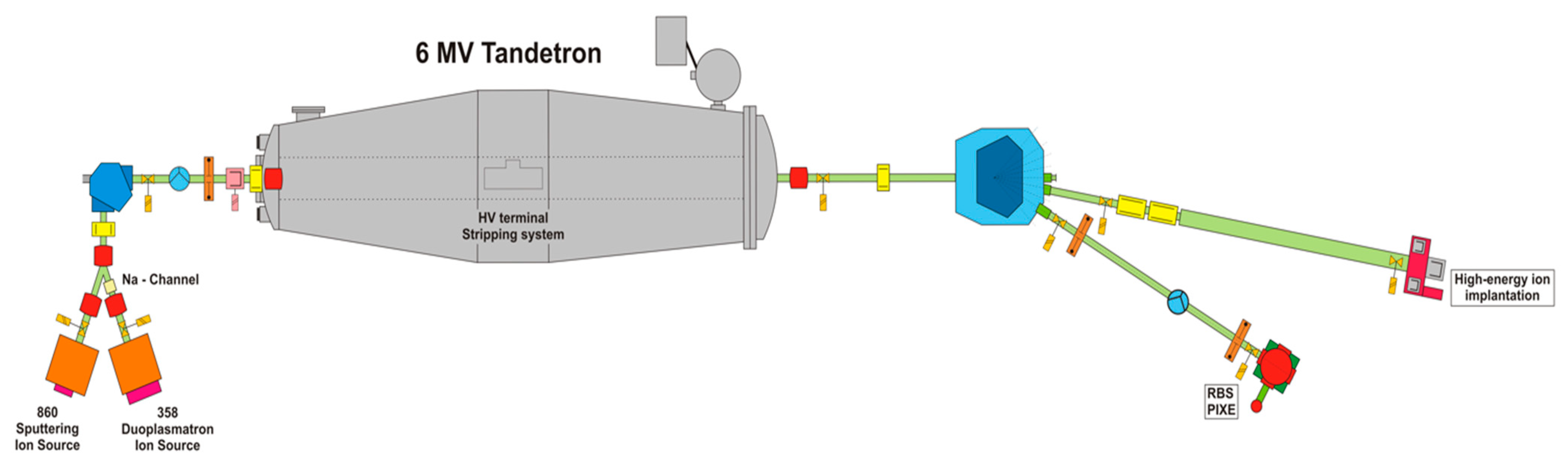
At significantly elevated temperatures, hydrogen can be released as one of the results of metal surfaces oxidation processes. It should be noted that in the operating conditions of SCWR, hydrogen is created as a radiolytic breakdown of water. In addition to conventional mechanical testing techniques (tensile, fracture toughness, etc.) characterising bulk properties of materials, it is important to investigate the applicability of surface and near-surface techniques sensitive to regions affected by a combination of corrosion and radiation degradation. Such a study requires a detailed understanding of the depth-sensitivity of the used methods and precise control of the damage distribution in accelerated irradiation experiments with light ions. We considered both these requirements in our long-term material study focused on the near-surface region of selected alloys foreseen for possible applications in nuclear installations via experimental radiation simulation via light ions (hydrogen, helium) implantation using our 6 MV Tandetron [9].
In this work, we address the limits of positron annihilation spectroscopy in the context of studies aimed at near-surface microstructural characterisation. In particular, we discuss the feasibility of using conventional unmoderated radioisotope sources in providing certain information on the trend of the evolution of radiation-induced changes in ion-implanted FeCr samples.

2. Application of Positron Annihilation Spectroscopy in Different Irradiation Experiments

While numerous papers have been published in the past on the PAS characterisation of accelerated material ageing studies [2,4], only a few studies until now addressed the question of the efficiency of the positron probing of the particular (e.g., ion-beam-modified) target volume. This is often a significant problem in the reproducibility of the PAS data, obtained from very different profiles of displacement damage where a major part of the signal might come from the undisturbed bulk rather than from the implanted layer. It is not the purpose of this work to discourage such studies but rather to provide some practical guidelines for approaching and carrying out some valuable information that can potentially compare different sets of irradiation experiments data.
Based on our experience with different irradiated nuclear materials [10,11,12], we aimed to provide an experimental validation of theoretical simulations of radiation effects using light ion implantation. Previous studies were mostly oriented on radiation-induced vacancy-type defects, their volume, and concentrations dependent on different fast neutron fluxes and fluences at reactor pressure vessel (RPV) steels [13]. Various non-destructive analyses performed were usually motivated by demand from authorities operating nuclear facilities to optimise the RPV annealing temperatures and to recover the RPV steels’ mechanical properties to achieve a safe and long-term operation. In addition to irradiated RPV surveillance specimens, we participated in the development and characterisation of reduced activation ferritic/martensitic (RAFM) steels with improved chemical composition. In recent years, we use PAS techniques also for research materials foreseen in Generation IV and thermonuclear fusion, which are expected to face increased displacement damage and higher operating temperatures. For the experimental simulation of high radiation damage, we typically use light ion bombardment [14,15,16].
The neutron embrittlement of nuclear structural materials is a complex topic depending on the actual type of steel used, neutron spectrum and corresponding transmutation reactions, and testing temperature, as well as on the availability of bulk samples. Many complementary spectroscopic methods have been developed to enable relevant investigation of miniaturised specimens and near-surface regions [17,18] to unravel the complex microscopic mechanisms responsible for neutron embrittlement of treated materials [19,20,21,22]. In reactor pressure vessel steels used in Russian nuclear power plants, it was generally accepted that irradiation-induced carbides are responsible for strengthening and radiation embrittlement [23,24]. In western European steels, which contain higher residual levels of copper and phosphorus, so-called radiation-enhanced diffusion can occur at temperatures over 300 °C. It forms small clusters which contribute to embrittlement. Neutron irradiation, together with thermal treatment, increase damage in the microstructure via small clusters formation (<5 nm in diameter). These new obstacles cause an increase of the yield stress as well as hardness and the ductile–brittle transition temperature.
The neutron embrittlement from the PAS point of view can be registered by changes in positron lifetimes which increase with radiation-induced vacancy type defects (point defects, screw, and edge dislocations, as well as small vacancy clusters) [25,26].
We focused our newest effort on ion (mostly H+, He++) implantation, which could be considered as an experimental simulation of radiation damage induced by neutrons due to a reasonably low (yet still accelerated) displacement damage rate. Implantation depth depends on the energies of the accelerated ions and usually ranges up to several micrometres. This is a near-surface region usually containing a corrosion layer, so the interpretation of the results is neither easy nor straightforward.
The aim of this paper is to discuss the feasibility of using conventional unmoderated radioisotope positron sources (particularly the 22Na) for the investigation of radiation-induced defects in ion-beam-modified samples. While the utilisation of slow-positron beam techniques to characterise the microstructural damage introduced by ion implantation is widely used by material scientists, radioisotope sources are often considered unsuitable for any charged particle irradiation experiment. In this paper, we demonstrate two different helium implantation experiments and discuss the possibility of using a Kapton-encapsulated 22Na source for the investigation of radiation damage in the microstructure of FeCr steels.
Since the early applications of positron annihilation lifetime spectroscopy (PALS), the radioisotope—22Na with maximum beta energy of about 545 keV is most frequently used as the positron source. Due to this energy, positrons can probe a depth in steel samples up to 100 micrometres. On the other hand, a slow-positron beam system such as the pulsed low-energy positron system (PLEPS) [27,28,29] investigates only a region up to 1 micrometre, using monoenergetic positrons with variable energy up to a few tens of keV. While the conventional PALS technique can provide primarily the bulk information, slow-positron beam data must inevitably consider the sample surface as a possible sink for radiation-induced defects as well as a trap for positrons. Measurement and interpretation of data obtained on thin multilayer systems and/or specimens with unsteadily distributed defects is, therefore, often a complicated task.
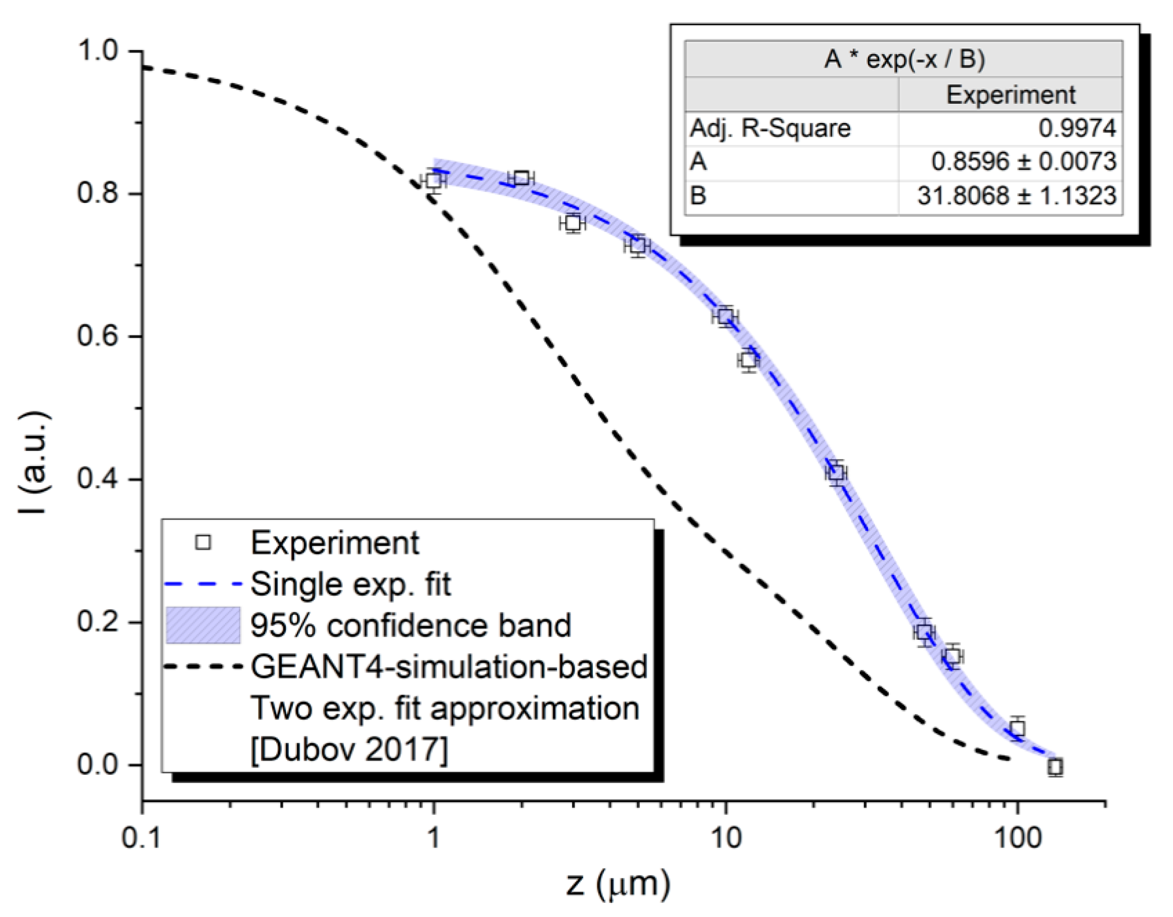
The implantation profiles of 22Na positrons are generally well known and depend mostly on materials densities [30,31,32]. There is, however, a problem with the accuracy of data for the near-surface region. In our previous studies, we have used positron stopping profiles either described by a single exponential law based on [31] or by a sum of two exponential functions based on [32]. We have also estimated the implantation profile by a simple discretisation of the continuous beta spectrum of 22Na and by theoretical estimation of mean implantation depth calculated for individual energy intervals.
Based on theoretical and empirical knowledge [33], the mean stopping depth of the positron into the sample, z ¯ , is the penetration depth of mono-energetic positron with energy E (in our case, we use Emax = 0.545 MeV) and to the density of the positron bombarded material ρ as follows:
z ¯ [ cm ] = A E [ keV ] n ρ [ g · cm 3 ]
Generally, A = 40 g · cm 2 · keV n and n = 1.6 are empirically determined constants, which can be used for most materials. The shape of the positron implantation profile is connected to the positron implantation energy. The so-called Makhovian distribution can be calculated according to Equation (2).
P ( z ,   E ) = m z m 1 z 0 m e ( z z 0 ) m ,
where z 0 is related to the mean implantation depth by z 0 = 2 z ¯ π , and the shape parameter m = 2 [33].
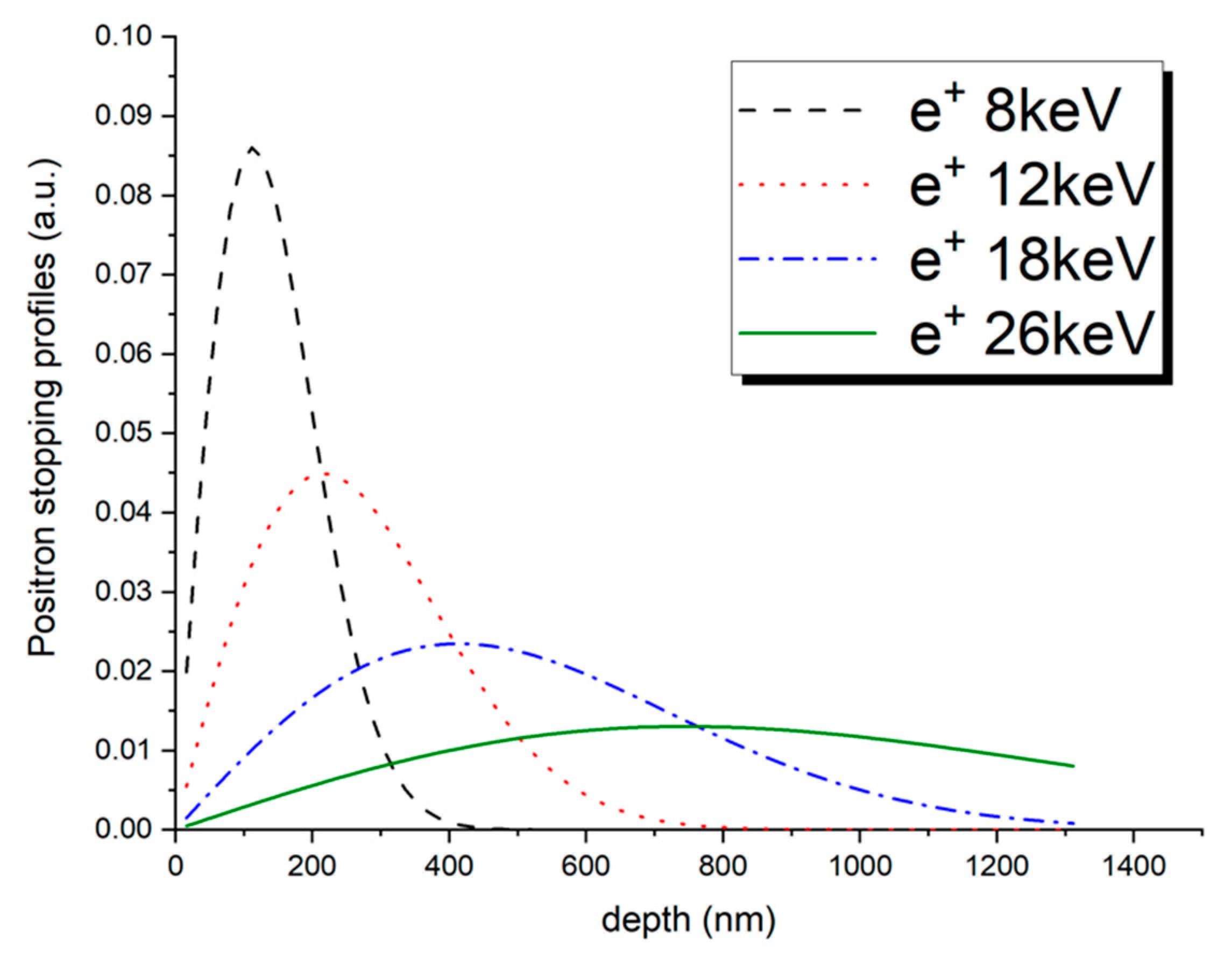
In the slow-positron technique, the shape of Makhovian distributions strongly depends on positron energy. The ability of positrons from slow-positron beams to penetrate into the material is limited and depends on characteristics explained in connection to Equation (1) but also on the positron energies (see Figure 1). It is important to note, however, that the range selectivity of the positron as a probe is significantly diminished for energies above ~10 keV. As can be seen in Figure 1, an approximate FWHM value (full width in half of the maximum) of 18 keV positron beam in Fe is higher than the actual mean stopping depth. In other words, the obtained annihilation signal comes roughly from a depth of 400 nm ± 200 nm. In a narrow near-surface implantation profile, this might probe the whole damage peak with a non-negligible contribution of deeper undisturbed bulk.
In contradiction to the slow-positron stopping profiles, the behaviour of fast (conventional) positrons is different. According to the theoretical considerations and calculations referred to above, the maximal level of depth of 22Na positrons implanted in Fe is close to 100 μm, with about 95% positrons stopped in 60 μm, and the mean implantation depth is of about 27 μm. In this paper, we address an ‘extreme’ case of using Kapton-encapsulated 22Na source for investigation of ion-bombarded Fe-Cr-C alloys with as thin as 1 micrometre of a severely damaged layer.

3. Irradiation Experiments and PAS Characterisation

Various irradiation experiments utilising particularly light ions were performed or are being performed at the ion-beam laboratory of the Slovak University of Technology, located in Trnava, using the 6 MV Tandetron accelerator [9]. A schematic of this accelerator with photos of the facility and irradiation chambers is shown in Figure 2.
The current design of a sample holder at the STU 6 MV Tandetron accelerator for a helium implantation experiment is shown in Figure 3. Samples of various f/m steels were mounted so that every sample contained two edges shielded with washers, providing an unirradiated reference area for various surface investigations (e.g., nanoindentation and atomic force microscopy).
To assess the applicability of radioisotope positron sources in studies concerning low-to-medium energy ion implantations (i.e., a maximum of few tens of micrometres deep layers), positron stopping profile was experimentally measured and compared with GEANT4 (CERN, Geneva, Switzerland) simulation using the same-source sandwiched geometry. In this experiment, a Kapton-encapsulated 22Na positron source was used. This source was sandwiched in between two stacks of Fe foils backed by either a polyimide sheet (Grade Upilex; Goodfellow Cambridge Ltd., Huntingdon, UK) or Si monocrystal. These ‘backing materials’ were used due to their characteristic lifetime 220 ps or 382 ps, respectively. The Fe foils of thickness ranging from 1 μm were available from a commercial supplier. To determine the positron absorption in Fe, the source contributions were calculated for selected thicknesses. Finally, the source contribution varied in range, i.e., 8 and 23% for the 1 μm and 135 μm Fe foil, respectively. Our digital positron lifetime spectrometer setup was used for scheduled measurements. The timing resolution (FWHM) was stable at the level of about 167 ps. The lifetime spectra with more than 1 × 10⁶ counts were measured by use of a conventional 22Na positron source with an activity of about 3.5 MBq. The spectra were deconvoluted via the LT program [34]. Due to possible microstructural defects in the investigated Fe foils, produced in the manufacturing process, which could be potentially mistaken for the ‘backing material’, all measurements were performed with both, Si and UPILEX backing. Having the lifetime data obtained using both materials, with substantially different characteristic positron lifetimes (220 ps for Si and 382 ps for UPILEX), we were able to reliably subtract the source contribution.
The positron stopping profile obtained from the PALS experiments can be seen in Figure 4, together with the two-exponential approximation from [32]. As can be seen from Figure 4, the theoretical simulation differs considerably from the experimentally obtained stopping profile [35], particularly in the range 5–50 μm. A possible reason for this discrepancy is the difference between the simplified simulation geometry and the real geometry used in our experiments. It seems that, while the theoretical simulation using the GEANT4 code provides a reasonable quick estimation of the positron stopping for simple models, complex geometries utilising various laboratory-made positron sources and realistic samples still require an experimental approach. Therefore, in further analysis, we used the stopping profile described by the exponential fit from Figure 4. For more details on the experiment using stacking foil samples, readers are referred to [35].

4. Results and Discussion

To assess the limits of the applicability of the 
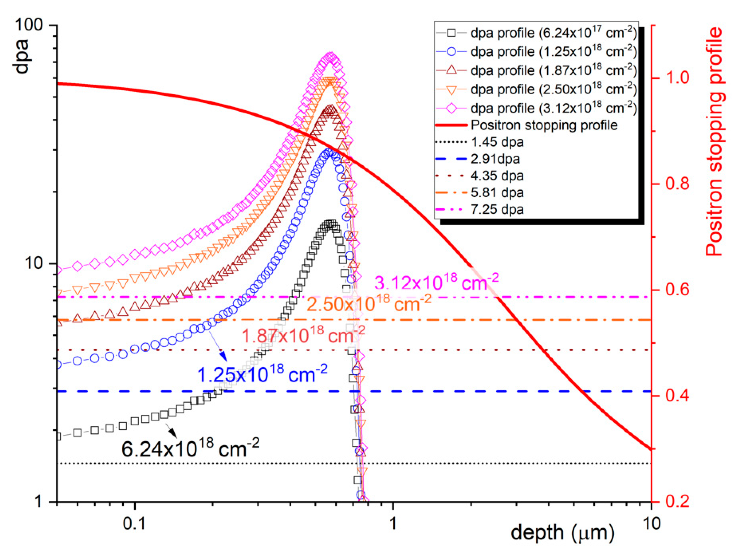
22Na source in the characterisation of near-surface displacement damage in ion bombardment experiments, we investigated three Fe-Cr-C alloys with different amounts of Cr content, implanted by 250 keV helium ions to five different fluencies. Using our experimental positron stopping profile, we calculated the mean values of displacement damage levels (dpa) for all ion fluencies. These values were averaged over the whole positron stopping profile, including the un-implanted zero-damage values in deeper bulk. As can be seen in Figure 5, they are considerably lower than the dpa peak values. It is worth noting that the presented correction of displacement damage values using any positron stopping profile (based on either theoretical simulation or experimental data) provides more realistic data for further interpretation. As long as the ion-implantation damage peak is not situated well below the 90% positron range, the positron stopping profile must be considered in the reporting of the dpa values.
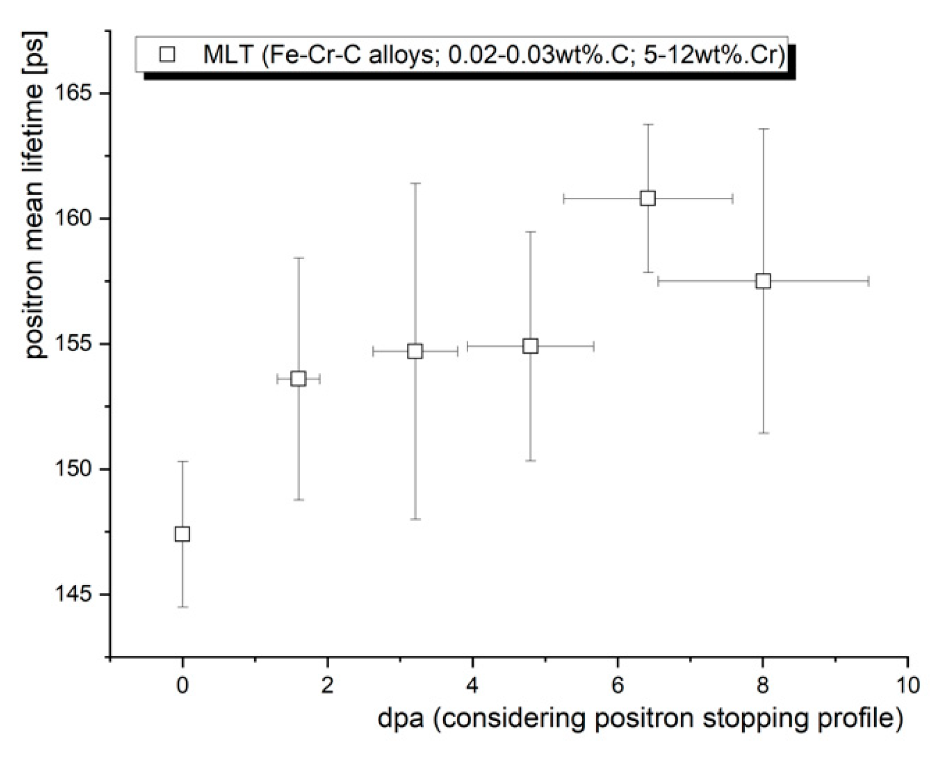
Figure 6 shows the positron mean lifetime (MLT) as a function of dpa. The MLT, as a statistically most reliable parameter, clearly shows that non-negligible positron trapping at radiation-induced defects has been observed after the 250 keV He implantation. It is important to note that the contribution of the positrons trapped at radiation-induced defects is reduced by helium occupying some of these defects and also by blistering and partial exfoliation (reaching up to 15% at the highest fluence) of the implanted layer. Although this experiment did not allow to us perform any quantitative analysis of the radiation defects in the studied samples, it confirmed that the introduced damage can be distinguished by positrons from conventional radioisotope positron sources.
It is also important to note that while the dpa values corrected to positron stopping profile provide a better estimation of displacement damage in the probed region, the number of displacements per atom is just one of the irradiation parameters to consider. The irradiation temperature and the helium concentration profile are often the most important parameters affecting the behaviour of the irradiated material. A detailed discussion on the effect of the displacement damage and helium production rates on the microstructural evolution of irradiated f/m steels was published in our previous paper [36]. For comparison, similar damage ~10 dpa but with a much lower concentration (production rate) of helium (<2000 appm) led to a positron mean lifetime of 200–220 ps in f/m steel irradiated in spallation neutron target [37]. Nevertheless, the trend of the evolution of the displaced microstructure can be reasonably captured by the presented approach.
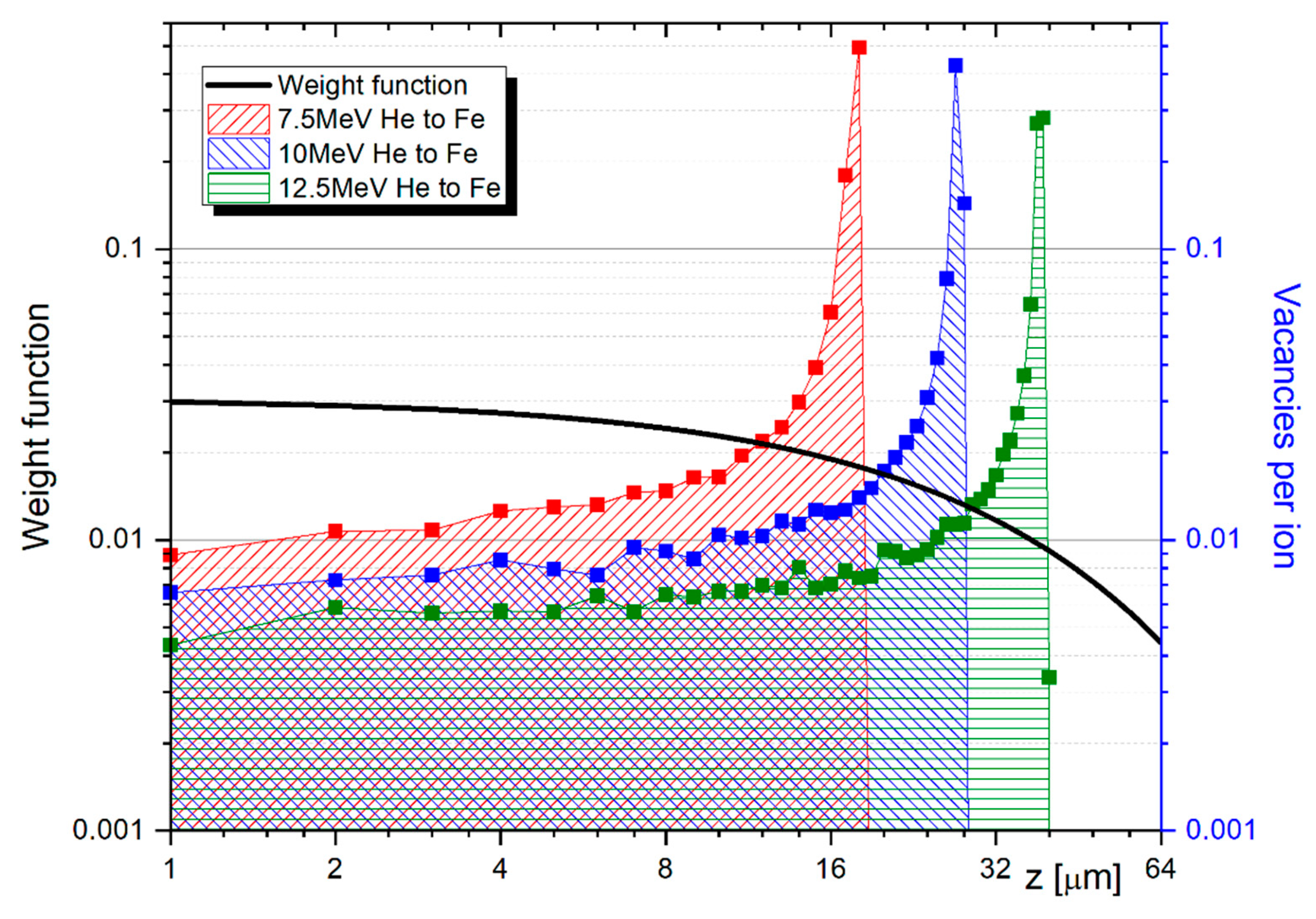
Here, an implantation profile produced in Fe by consequential implantation of He ions with energies 12.5, 10, and 7.5 MeV is discussed. Considering lattice-binding energy of 40 eV and using the ‘quick Kinchin–Pease’ calculation option, such implantations result in a production of about 140, 160, and 180 stable vacancies per ion, respectively. The vacancy production was calculated using the Norgett–Robinson–Torrens (NRT) model [38], which does not consider the temperature-depending recombination processes. Displacement damage distribution is similar to Bragg profile, where the maxima of implantation depth are close to 19, 29, and 40 mm, respectively (Figure 7). These thicknesses can be assigned to 52.2, 64.7, and 74.7% of 22Na positrons probing the region modified by ion implantation. To provide a more accurate number of produced vacancies with respect to the applied PAS technique, the SRIM data were again averaged over distance (depth), reflecting the shape of the positron stopping profile. Thus, we obtain 3.50, 2.80, and 2.04 stable vacancies per implanted ion for the 7.5, 10, and 12.5 MeV He ions, respectively. It can be assigned to ≈1.94%, 1.55%, and 1.20% of the displacement damage which was caused by performed ion implantation. In the first approach, this sensitivity of the PALS technique seems quite poor. On the other hand, the contribution to the total displacement damage value obtained from SRIM is primarily from the Bragg peak region, while the positron annihilation signal comes mostly from the area in between the narrow peaks. The actual data provided by PALS characterisation are, in fact, much more realistic in terms of displacement damage, and the interpretation of the results is more relevant and accurate compared with the interpretation using direct SRIM data.
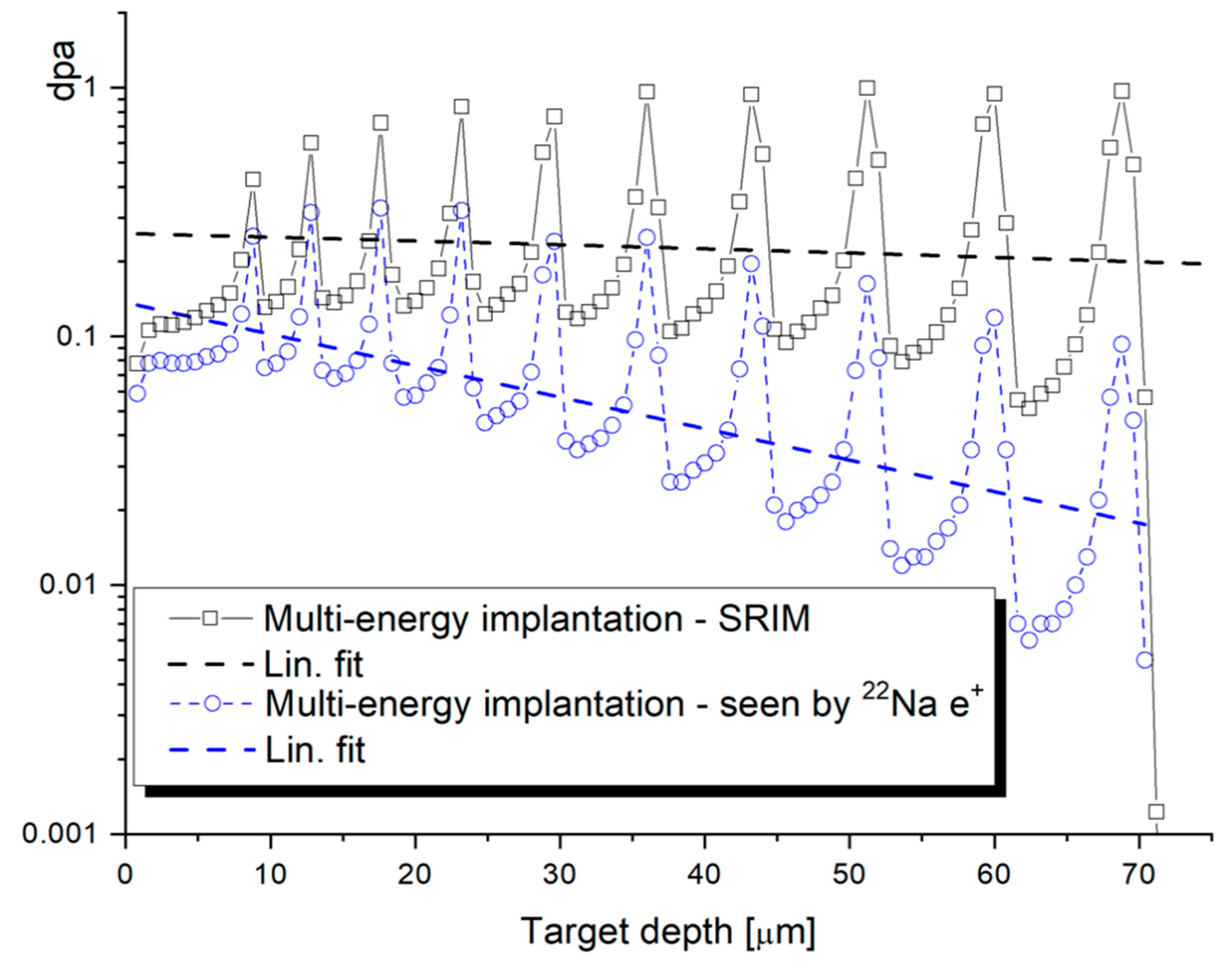
When we consider the maximum acceleration energy for He ions, available at the Tandetron accelerator at STU, we can propose an irradiation experiment inducing damage layer in steel as much as 70 µm. To obtain a quasi-uniform profile, we simulated an experiment with consequent implantation of 10 different ion energies, ranging from 4.5 MeV to 18 MeV, with a total fluence of 5.5 × 1017 cm−2. Detailed parameters of such implantation are listed in Table 1. The number of vacancies was calculated using data provided by the SRIM output file vacancy.txt file, as well as by using the NRT model using damage energy Tdam [37]. As can be seen in Table 1, the NRT formula results in higher values (by about 35%) than the ones obtained from SRIM. Additionally, dpa values were obtained from the number of generated vacancies and iron atoms. By integrating of displacement damage profile (black squares in Figure 8), we obtain average displacement damage of 0.204 dpa, produced by the given He implantation. After correcting the dpa value to the 22Na positron stopping profile, we obtain 0.064 dpa (the corresponding profile is in blue circles in Figure 8), i.e., only about one-third of the actually implanted damage.

5. Summary

Our work aimed to analyse the application limits of positron annihilation spectroscopy for the study of defects in nuclear structural materials exposed to charged particle irradiation. We discussed the results of conventional PALS experiments obtained on three different Fe-Cr-C alloys implanted by 250 keV helium ions. Despite a less than 1 μm thin ion-modified layer, positron mean lifetimes, obtained from implanted samples by using 22Na source, increase over the reference values of unirradiated materials beyond the statistical error. While no detailed quantitative information on radiation defects can be derived from this kind of experiment on a single sample, a meaningful indication of the trends of defects’ behaviour can be obtained using multiple different fluencies, irradiation/annealing temperatures, corrosion ageing, ion fluxes, etc. In this paper, we further outlined some details of ongoing helium implantation experiments utilising multiple beam energies up to 18 MeV. This experiment was proposed to maximise the potential of experiments using the 22Na source, providing a quasi-uniform damage profile and scientifically interesting displacement damage rates and helium production rates.

Author Contributions

Conceptualisation, V.S. and V.K.; methodology, V.S. and V.K.; software, M.P.; validation, J.D., S.S., and V.K.; formal analysis, V.S.; investigation, V.S. and V.K.; resources, M.P. and P.N.; writing—original draft preparation, V.S.; writing—review and editing, V.S. and V.K.; supervision, V.S. All authors have read and agreed to the published version of the manuscript.

Funding

This study received funding from the Euratom research and training programme 2019-2020 under Grant Agreement No 945234 (ECC-SMART) and from EC in the frame of H2020 Grant Agreement No 945041 (SafeG). The project was partially granted also by the Scientific Grant Agency of the Ministry of Education of Slovak Republic and the Slovak Academy of Sciences VEGA Project No. 1/0330/18 and 1/0395/20, as well as from the European Regional Development Fund, Project No. ITMS2014+: 313011U413.

Data Availability Statement

Not applicable.

Acknowledgments

This study received funding from EC in the frame of H2020 Grant Agreements No 945234 (ECC-SMART) and No. 945041 (SafeG). The project was partially granted also by the Scientific Grant Agency of the Ministry of Education of Slovak Republic and the Slovak Academy of Sciences VEGA Projects No. 1/0330/18, 1/0382/20, and 1/0395/20, as well as from the European Regional Development Fund, Project No. ITMS2014+: 313011U413.

Conflicts of Interest

The authors declare no conflict of interest.

References

  1. Yvon, P. Structural Materials for Generation IV Nuclear Reactors; Elsevier: Amsterdam, The Netherlands, 2016; ISBN 9780081009123. [Google Scholar]
  2. Lear, C.R.; Song, M.; Wang, M.; Was, G.S. Dual ion irradiation of commercial and advanced alloys: Evaluating microstructural resistance for high dose core internals. J. Nucl. Mater. 2019, 516, 125–134. [Google Scholar] [CrossRef]
  3. Selim, F.A. Positron annihilation spectroscopy of defects in nuclear and irradiated materials—A review. Mater. Charact. 2021, 174, 110952. [Google Scholar] [CrossRef]
  4. Zinkle, S.J.; Busby, J.T. Structural materials for fission and fusion energy. Mater. Today 2009, 12, 12–19. [Google Scholar] [CrossRef]
  5. Wirth, B.D. How does radiation damage materials. Science 2007, 318, 923–924. [Google Scholar] [CrossRef] [PubMed]
  6. Guzonas, D.; Novotny, R.; Pentilla, S.; Toivonen, A.; Zheng, W. Materials and Water Chemistry for Supercritical Water-Cooled Reactors; Elsevier: Amsterdam, The Netherlands, 2017; ISBN 9780081020494. [Google Scholar]
  7. Guzonas, D.; Novotny, R. Supercritical water-cooled reactor materials—Summary of research and open issues. Prog. Nucl. Energy 2014, 77, 361–372. [Google Scholar] [CrossRef]
  8. Pioro, I.; Mokry, S. Thermophysical Properties at Critical and Supercritical Conditions. Heat Transf. Theor. Anal. Exp. Investig. Ind. Syst. 2011, 573–592. [Google Scholar] [CrossRef] [Green Version]
  9. Noga, P.; Dobrovodsky, J.; Vana, D.; Beno, M.; Zavacka, A.; Muska, M.; Halgas, R.; Minarik, S.; Riedlmajer, R. A new ion-beam laboratory for materials research at the Slovak University of Technology. Nucl. Instrum. Meth. Phys. Res. B 2017, 409, 264–267. [Google Scholar] [CrossRef]
  10. Slugen, V.; Segers, D.; De Bakker, P.M.A.; De Grave, E.; Magula, V.; Van Hoecke, T.; Van Waeyenberge, B. Annealing behaviour of reactor pressure-vessel steels studied by positron-annihilation spectroscopy, Mössbauer spectroscopy and transmission electron microscopy. J. Nucl. Mater. 1999, 274, 273–286. [Google Scholar] [CrossRef]
  11. Slugen, V.; Kögel, G.; Sperr, P.; Triftshäuser, W. Positron annihilation studies of neutron irradiated and thermally treated reactor pressure vessel steels. J. Nucl. Mater. 2002, 302, 89–95. [Google Scholar] [CrossRef]
  12. Slugen, V.; Hein, H.; Sojak, S.; Veternikova, J.; Petriska, M.; Sabelova, V.; Pavuk, M.; Hinca, R.; Stacho, M. Evaluation of the Reactor Pressure Vessel Steels by Positron Annihilation. J. Nucl. Mater. 2013, 442, 499–506. [Google Scholar] [CrossRef]
  13. Slugen, V. Safety of VVER-440 Reactors—Barriers Against Fission Products Release; Springer: London, UK, 2011. [Google Scholar]
  14. Pecko, S.; Sojak, S.; Slugen, V. Comparative study of irradiated and hydrogen implantation damaged German, RPV steels from PAS point of view. Appl. Surf. Sci. 2014, 312, 172–175. [Google Scholar] [CrossRef]
  15. Krsjak, V.; Egger, W.; Petriska, M.; Sojak, S. Helium implanted FeCr alloys studied by positron annihilation lifetime technique. Probl. At. Sci. Technol. 2009, 4, 109–115. [Google Scholar]
  16. Sabelova, V.; Kršjak, V.; Kuriplach, J.; Dai, Y.; Slugen, V. Coincidence Doppler broadening study of Eurofer 97 irradiated in spallation environment. J. Nucl. Mater 2015, 458, 350–354. [Google Scholar] [CrossRef]
  17. Koutsky, J.; Kocik, J. Radiation Damage of Structural Materials; Academia: Prague, CR, USA, 1994. [Google Scholar]
  18. Phythian, W.J.; English, C.A. Microstructural Evolution in Reactor Pressure-Vessel Steels. J. Nucl. Mater. 1993, 205, 162–177. [Google Scholar] [CrossRef]
  19. Slugen, V.; Kryukov, A. Microstructural study of WWER reactor pressure vessel steels. Nucl. Eng. Des. 2013, 261, 308–312. [Google Scholar] [CrossRef]
  20. Becvar, F.; Jirasková, Y.; Keilova, E.; Kocik, J.; Lestak, L.; Prochazka, I.; Sedlak, B.; Sob, M. Positron annihilation studies on neutron irradiated CrMoV-type of reactor pressure vessel steels. Mat. Sci. Forum. 1992, 105–110, 901–907. [Google Scholar] [CrossRef]
  21. Kočík, J.; Keilova, E. Radiation damage structure of VVER (Cr-Mo-V type) RPV steels. J. Nucl. Mater. 1990, 172, 126–132. [Google Scholar] [CrossRef]
  22. De Bakker, P.M.A. RPV steel embrittlement studied by Mossbauer spectroscopy. In Proceedings of the International Conference on the Applications of the Mössbauer Effect, ICAME-95, Rimini, Italy, 10–16 September 1995; Ortalli, I., Ed.; SIF: Bologna, Italy, 1996; pp. 145–151. [Google Scholar]
  23. Bohmert, J.; Grosse, M. Proceedings of Jahrestagung Kerntechnik, Munich, Germany, 26–28 May 1998; Inforum Verlag: Bonn, Germany, 1998; pp. 741–746. [Google Scholar]
  24. Brauer, G.; Puska, M.; Sob, M.; Korhonen, T. Positron affinity for precipitates in reactor pressure vessel steels. Nucl. Eng. Desg. 1995, 158, 149–162. [Google Scholar] [CrossRef]
  25. Hautojärvi, P. Positrons in Solids; Springer: Berlin, Germany, 1979. [Google Scholar]
  26. Dupasquier, A.; Mills, A.P. Positron Spectroscopy of Solids; IOS Press: Amsterdam, The Netherlands, 1995. [Google Scholar]
  27. Sperr, P.; Egger, W.; Kögel, G.; Dollinger, G.; Hugenschmidt, C.; Repper, R.; Piochacz, C. Status of the pulsed low energy positron beam system (PLEPS) at the Munich Research Reactor FRM-II. Appl. Surf. Sci. 2008, 255, 35–38. [Google Scholar] [CrossRef]
  28. Hugenschmidt, C. Positron in surface physics. Surf. Sci. Rep. 2016, 71, 547–594. [Google Scholar] [CrossRef] [Green Version]
  29. Hugenschmidt, C.; Löwe, B.; Mayer, J.; Piochacz, C.; Pikart, P.; Repper, R.; Stadlbauer, M.; Schreckenbach, K. Unprecedented intensity of low-energy positron beam. Nucl. Instrum. Meth. Phys. Res. A 2008, 593, 616–618. [Google Scholar] [CrossRef]
  30. Dryzek, J.; Singleton, D. Implantation profile and linear absorption coefficients for positrons injected in solids from radioactive sources 22Na and 68Ge/68Ga. Nucl. Instrum. Meth. Phys. Res. B 2006, 252, 197–204. [Google Scholar] [CrossRef]
  31. Linderoth, S.; Hansen, H.E.; Nielsen, B.; Petersen, K. Positron transmission and effective mass absorption coefficient in nickel. Appl. Phys. A 1984, 33, 25–28. [Google Scholar] [CrossRef]
  32. Dubov, L.Y.; Akmalova, Y.A.; Stepanov, S.V.; Funtikov, Y.V.; Shtotsky, Y.V. Evaluation of positron implantation profiles in various materials for 22Na source. Acta Phys. Pol. A 2017, 132, 1482–1485. [Google Scholar] [CrossRef]
  33. Krause-Rehberg, R.; Leipner, H.S. Positrons in Semiconductors; Springer: Berlin, Germany, 1997. [Google Scholar]
  34. Kansy, J. LT for Windows; Version 9.0; Silesian University: Gliwice, Poland, 2007. [Google Scholar]
  35. Krsjak, V.; Degmova, J.; Lauko, R.; Snopek, J.; Saro, M.; Sedlackova, K.; Sojak, S.; Petriska, M.; Farkas, G.; Dai, Y.; et al. Positron annihilation spectroscopy studies of irradiated Fe-based alloys using different radioisotope sources. Nucl. Instrum. Meth. Phys. Res. B 2018, 434, 73–80. [Google Scholar] [CrossRef]
  36. Krsjak, V.; Degmova, J.; Sojak, S.; Slugen, V.J. Effects of displacement damage and helium production rates on the nucleation and growth of helium bubbles—Positron annihilation spectroscopy aspects. Nucl. Mater. 2018, 499, 38–46. [Google Scholar] [CrossRef]
  37. Sato, K.; Xu, Q.; Yoshiie, T.; Dai, Y.; Kikuchi, K. A proposed method of calculating displacement dose rates. J. Nucl. Mater. 2012, 431, 52–56. [Google Scholar] [CrossRef]
  38. Norgett, M.J.; Robinson, M.T.; Torrens, I.M. A proposed method of calculating displacement dose rates. Nucl. Eng. Des. 1975, 33, 50–54. [Google Scholar] [CrossRef]
Figure 1. Positron stopping profiles in Fe, corresponding to different beam energies.
Metals 11 01689 g001
Figure 2. The 6 MV Tandetron ion accelerator at the Advanced Technologies Research Institute, Slovak University of Technology.
Metals 11 01689 g002aMetals 11 01689 g002b
Figure 3. Design of a sample holder for helium implantation experiment at 6 MV Tandetron ion accelerator at STU.
Metals 11 01689 g003
Figure 4. Experimentally obtained positron annihilation depth profile in Fe and the two-exponential approximation obtained from GEANT4 simulation.
Metals 11 01689 g004
Figure 5. Displacement damage profiles obtained from SRIM simulation (Fe lattice; ‘quick Kinchin–Pease’ calculation option; lattice binding energy of 40 eV) and the apparent mean dpa values (corrected to the positron depth distribution function) for different helium fluencies.
Metals 11 01689 g005
Figure 6. Average values of the positron mean lifetime for three Fe-Cr-C alloys implanted to five different fluencies.
Metals 11 01689 g006
Figure 7. Depth profiles of vacancies distribution according to implantation energies. The weight function characterising the stopping of positrons from the 22Na source was obtained from the experiment illustrated in Figure 4 and depicted the logarithmic scale.
Metals 11 01689 g007
Figure 8. Damage profile in Fe induced by He implantation with a total fluence of 5.5 × 1017 cm−2. Displacement damage–dpa profile as simulated by SRIM (black squares) vs. actual profile as ‘visible’ to positrons from conventional 22Na source (blue circles).
Metals 11 01689 g008
Table 1. Proposed multi-energy He-implantation characteristics.
Implantation1st2nd3rd4th5th6th7th8th9th10th
Energy [keV]18,00016,50015,00013,50012,00010,5009000750060004500
Max. penetration depth [um]71.562.552.544.537.530241813.59.5
Energy loss to phonons from Ions0.00020.00020.00020.00020.00020.00030.00030.00030.00040.0005
Energy loss to phonons from Recoils0.00090.0010.0010.00110.00120.00130.00140.00160.00190.0024
Vacancies/Ion from SRIM146136.8133130.4124.4121.4113.7106.210294.7
Tdam for NRT calculations [keV]19.819.81817.5516.816.815.314.2513.813.05
Number of stable vacancies produced—NRT model198198180175.5168168153142.5138130.5
Fluence [cm−2]1 × 10179 × 10168 × 10167 × 10166 × 10165 × 10164 × 10163 × 10162 × 10161 × 1016
Displacement damage [dpa]0.0330.0340.0320.0330.0320.0330.0300.0280.0240.016
Publisher’s Note: MDPI stays neutral with regard to jurisdictional claims in published maps and institutional affiliations.

