Review

A Review on Laser-Assisted Joining of Aluminium Alloys to Other Metals

1
Materials and Nanotechnology, SINTEF Industry, P.O. Box 4760 Torgarden, NO-7465 Trondheim, Norway
2
Materials Technology, SINTEF Manufacturing, P.O. Box 163, NO-2831 Raufoss, Norway
*
Author to whom correspondence should be addressed.
Metals 2021, 11(11), 1680; https://doi.org/10.3390/met11111680
Submission received: 30 August 2021 / Revised: 21 September 2021 / Accepted: 27 September 2021 / Published: 21 October 2021
(This article belongs to the Special Issue Welding Metallurgy)

Abstract

:
Modern industry requires different advanced metallic alloys with specific properties since conventional steels cannot cover all requirements. Aluminium alloys are becoming more popular, due to their low weight, high corrosion resistance, and relatively high strength. They possess respectable electrical conductivity, and their application extends to the energy sector. There is a high demand in joining aluminium alloys with other metals, such as steels, copper, and titanium. The joining of two or more metals is challenging, due to formation of the intermetallic compound (IMC) layer with excessive brittleness. High differences in the thermophysical properties cause distortions, cracking, improper dilution, and numerous weld imperfections, having an adverse effect on strength. Laser beam as a high concentration energy source is an alternative welding method for highly conductive metals, with significant improvement in productivity, compared to conventional joining processes. It may provide lower heat input and reduce the thickness of the IMC layer. The laser beam can be combined with arc-forming hybrid processes for wider control over thermal cycle. Apart from the IMC layer thickness, there are many other factors that have a strong effect on the weld integrity; their optimisation and innovation is a key to successfully delivering high-quality joints.

1. Introduction

Recently, the joining of dissimilar metals has gained much attention in the automotive, aerospace, and electrical power industries, due to growing demands in efficiency and specific properties for metals. Steel, as the most widely used metal, cannot fulfil certain demands and is partly substituted by modern Al, Cu or Ti alloys. As a result, the necessity of joining dissimilar metals has gained much attention in the past decade and is growing rapidly.
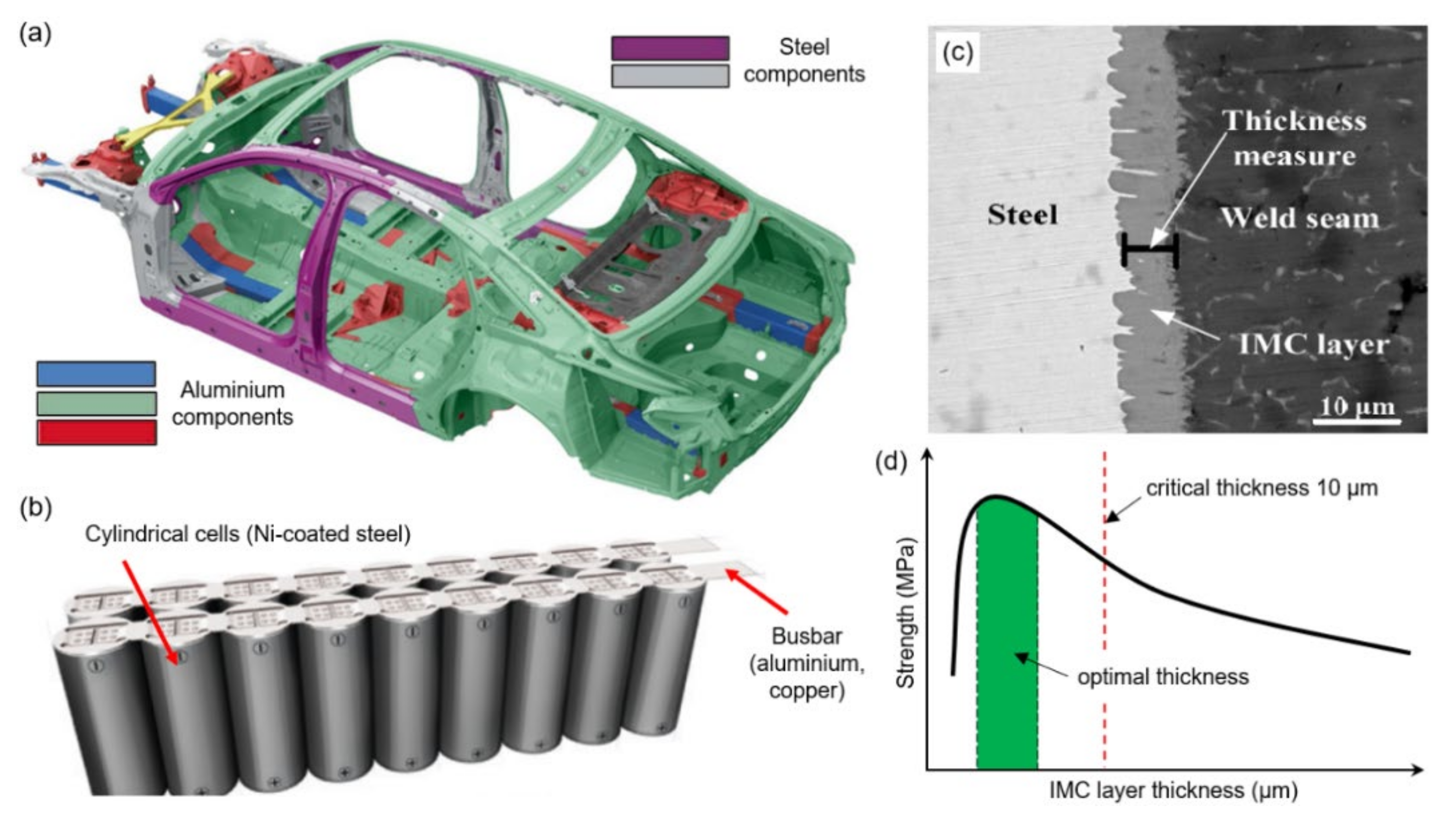
For car body production in the automotive industry, galvanised steel has been used for many years and is commonly welded by resistance spot welding. Aluminium is frequently applied for improved weight reduction and corrosion resistance. An example of different metal combinations in an automobile body structure is shown in Figure 1a. In the aerospace industry, also the combination of aluminium with titanium is becoming frequent, due to weight reduction. Friction stir welding (FSW) has gained more popularity since it may provide high-quality joints, due to low heat input [1]. However, the process has limited productivity and flexibility, compared to fusion welding processes. Batteries are an important part of society’s everyday needs, used in portable electronic devices, cordless power tools, energy storage, hybrid/electric vehicles, and many other applications. In the development of batteries, there are growing demands for weight reduction and an increase in corrosion resistance; therefore, parts made from steel in batteries are substituted with Al (weight reduction, higher electrical conductivity, corrosion resistance) and Cu (much higher electrical conductivity, corrosion resistance). Each individual battery cell (or cell unit) is connected, forming a pack of batteries (module), using a busbar (or terminal), which is now usually made from copper/aluminium, as exemplified in Figure 1b. Lithium–ion cells are the most dominant type among batteries in the automotive vehicle industry, due to having the highest energy density available [2], where the outer shells are often produced from nickel-plated steel. The pouch cell type is very popular and is produced in very large quantities, with more than 1 billion cells per year [3]. Individual battery cells are joined (in series or parallel) to modules (consisting of cell units) by high electrical conductivity material, which is usually copper or aluminium. According to Das et al. [
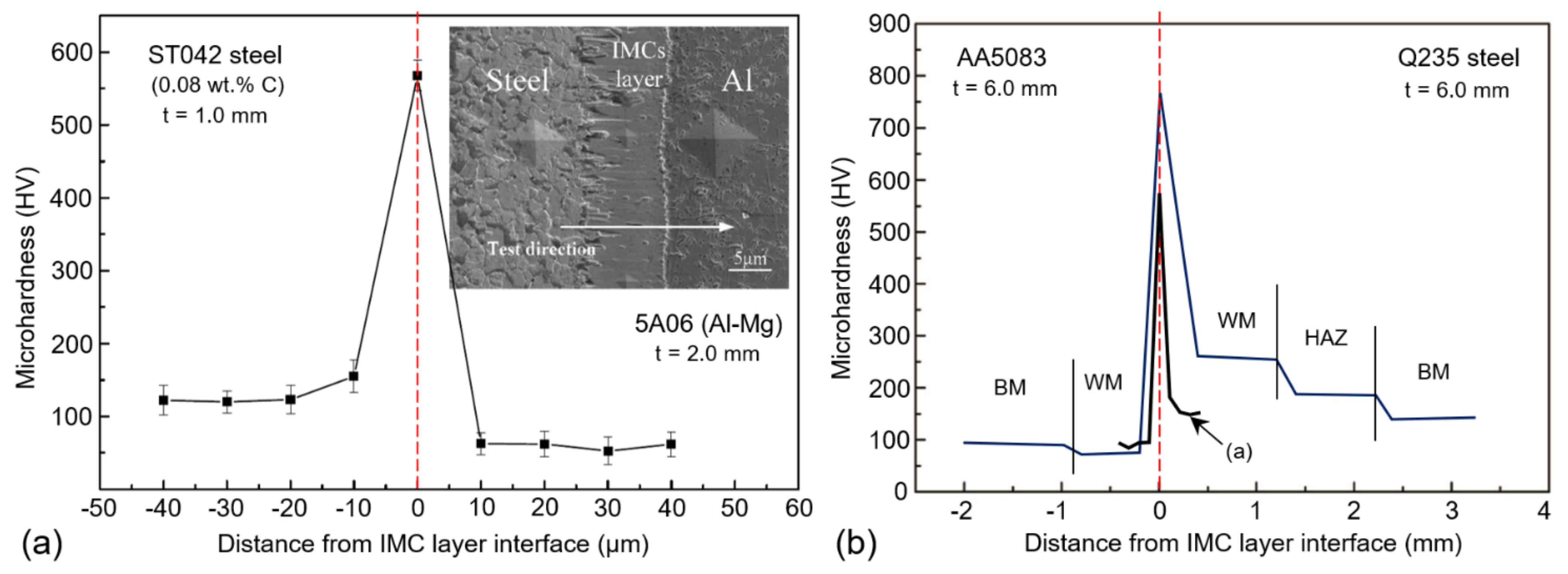
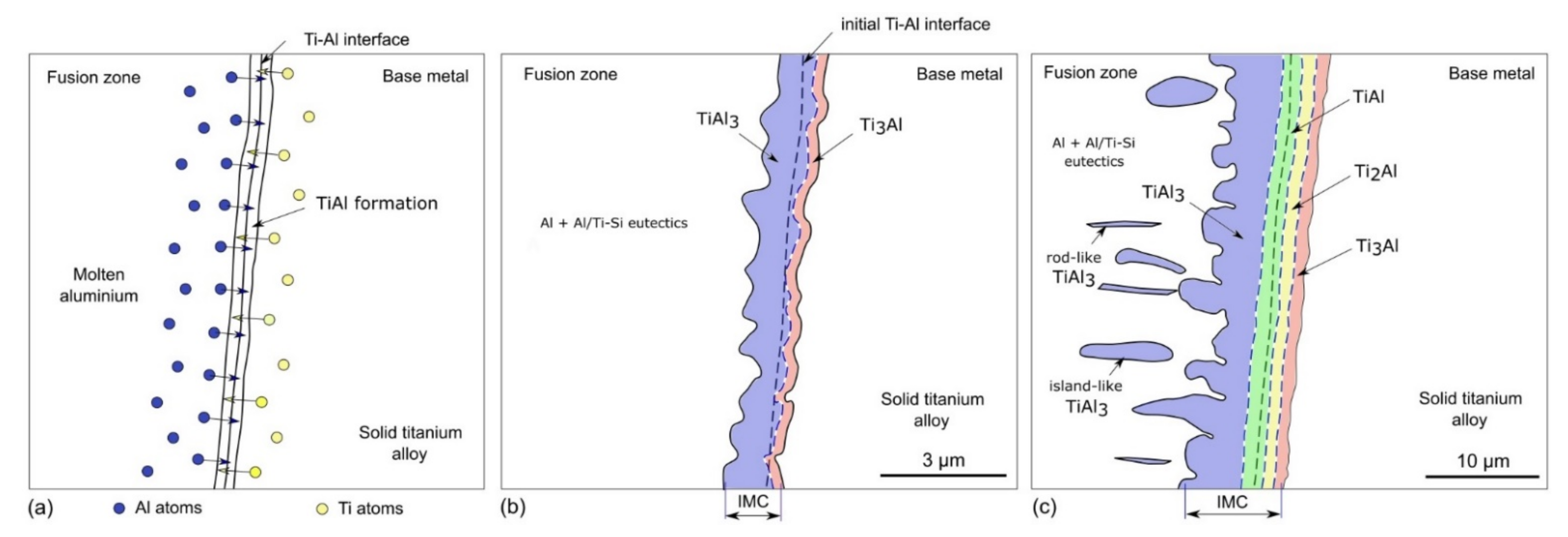
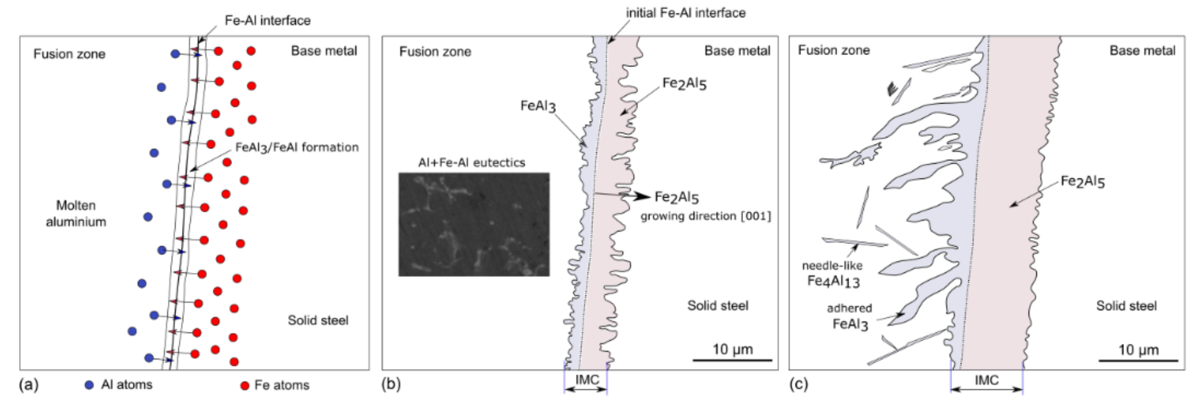
4], laser beam welding is a good alternative in the joining of electrical battery cells and pack level assembly since it may be used for different types of batteries. Aluminium-to-copper is particularly of high interest in the energy industry, due to the need for high electrical conductivity and weight reduction. Therefore, there is a growing demand for the joining of dissimilar metals, where aluminium is often one of metals, chosen for to its unique capability to significantly improve properties of the component/structure. However, there are many challenges and key factors in the joining of multi-material systems that need to be addressed. Aluminium and steel/Cu/Ti have a great difference in melting temperatures: 660 °C Al to 1520 °C/1083 °C/1660 °C for steel/Cu/Ti, respectively. In fusion welding, more aluminium is melted in the fusion zone and contraction forces are increased during solidification, causing hot tearing in the low melting point alloy (Al) at or nearby parent material (weld interface). Larger difference in thermal expansion coefficients strongly influence the residual stress distribution after welding, and hence, affect the component integrity. Aluminium has much greater heat conduction than steel and Ti, and thus, higher energy intensity is required for melting. Moreover, the temperature distribution may be highly asymmetric, with a complex residual stress pattern. Therefore, the location of melting and heat concentration is an important factor to consider. A critically important factor is the inevitable formation of the brittle intermetallic compound (IMC) layer (see example in 
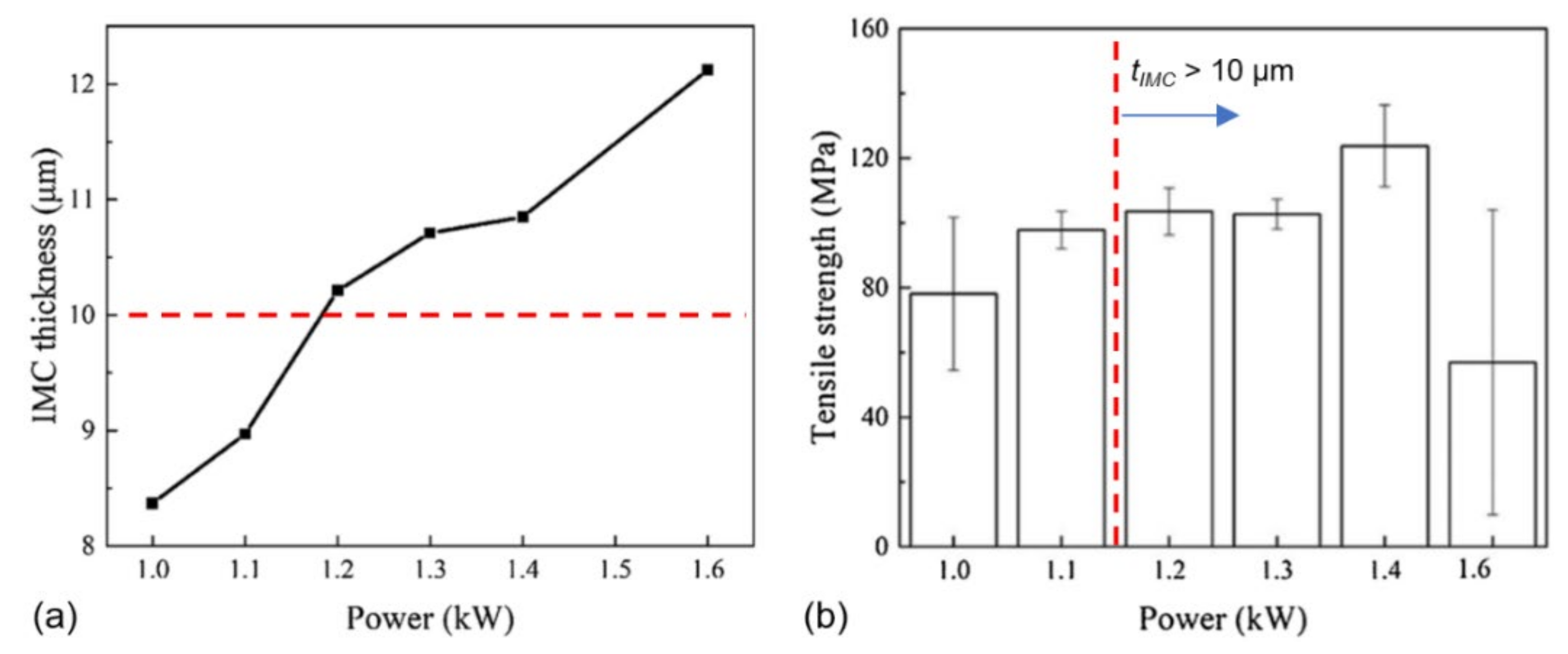
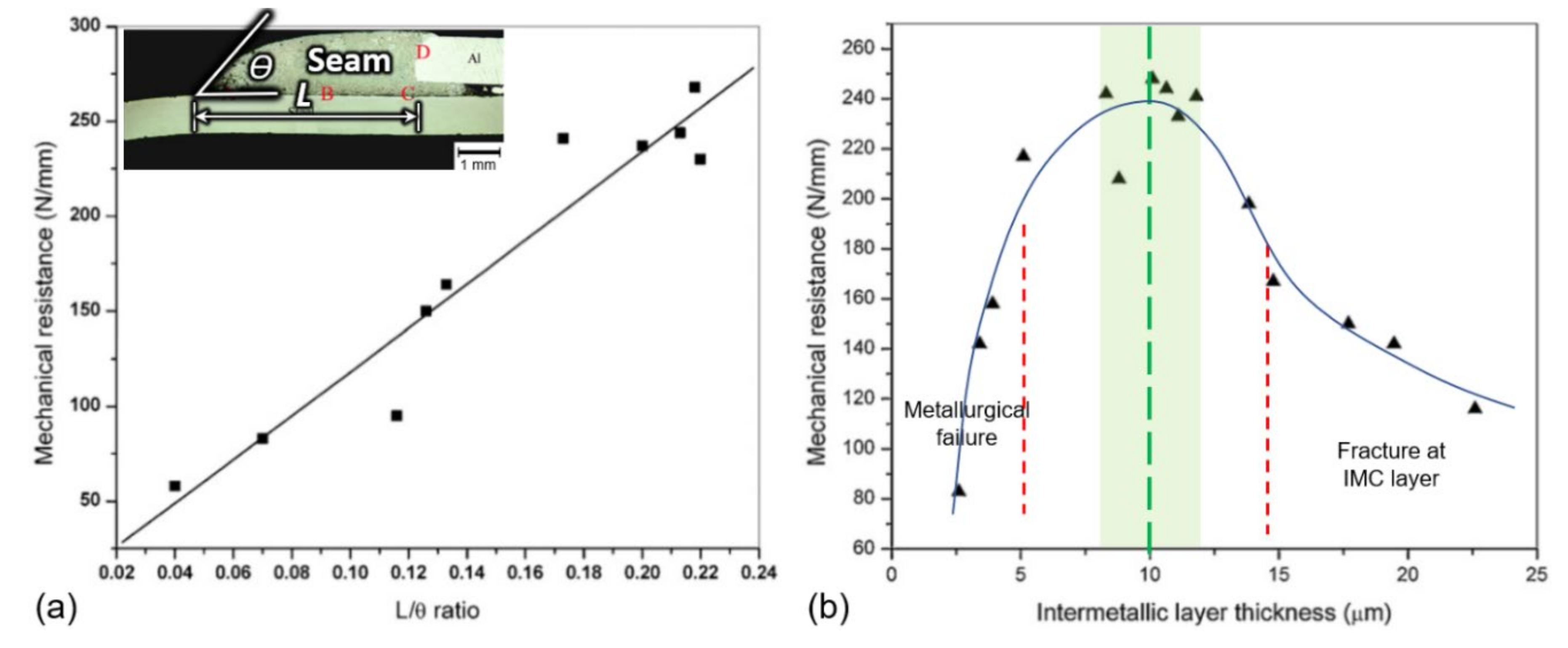
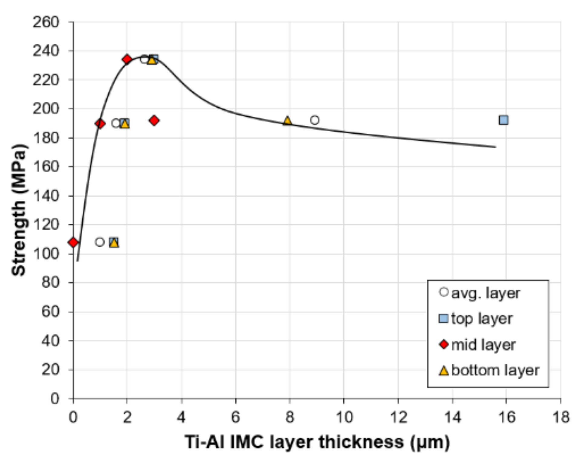
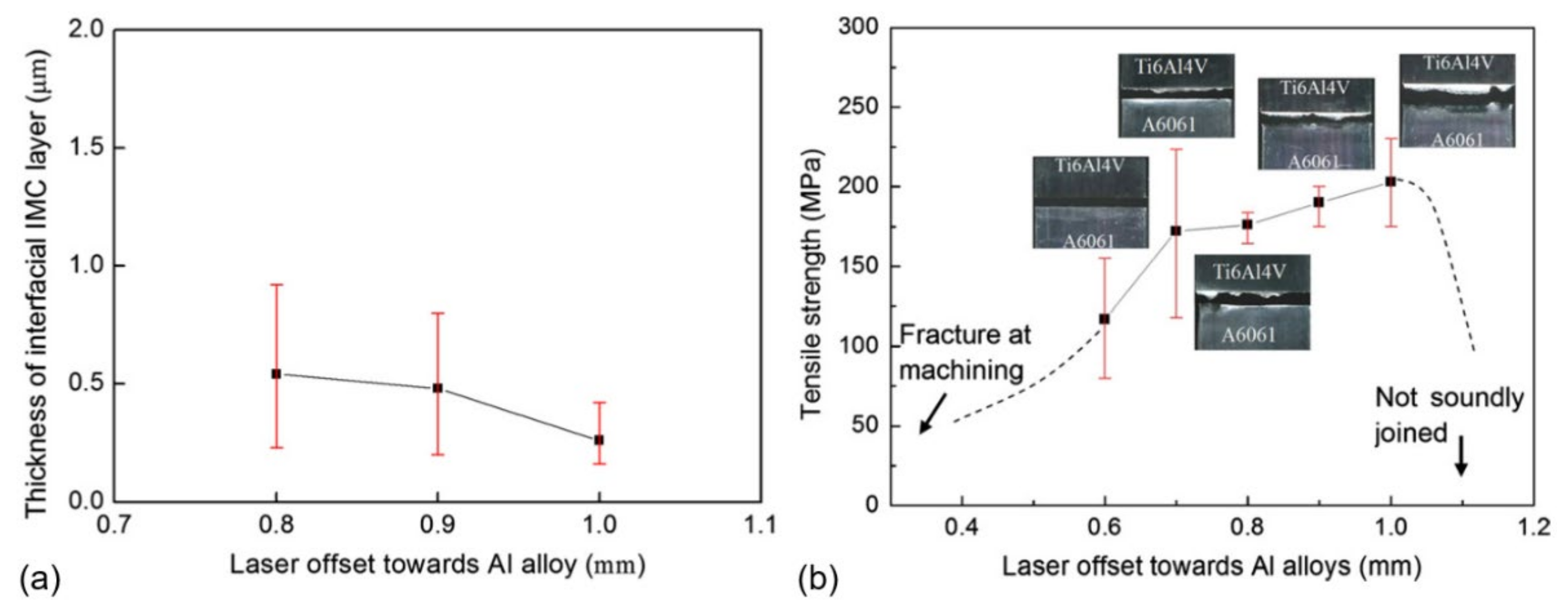
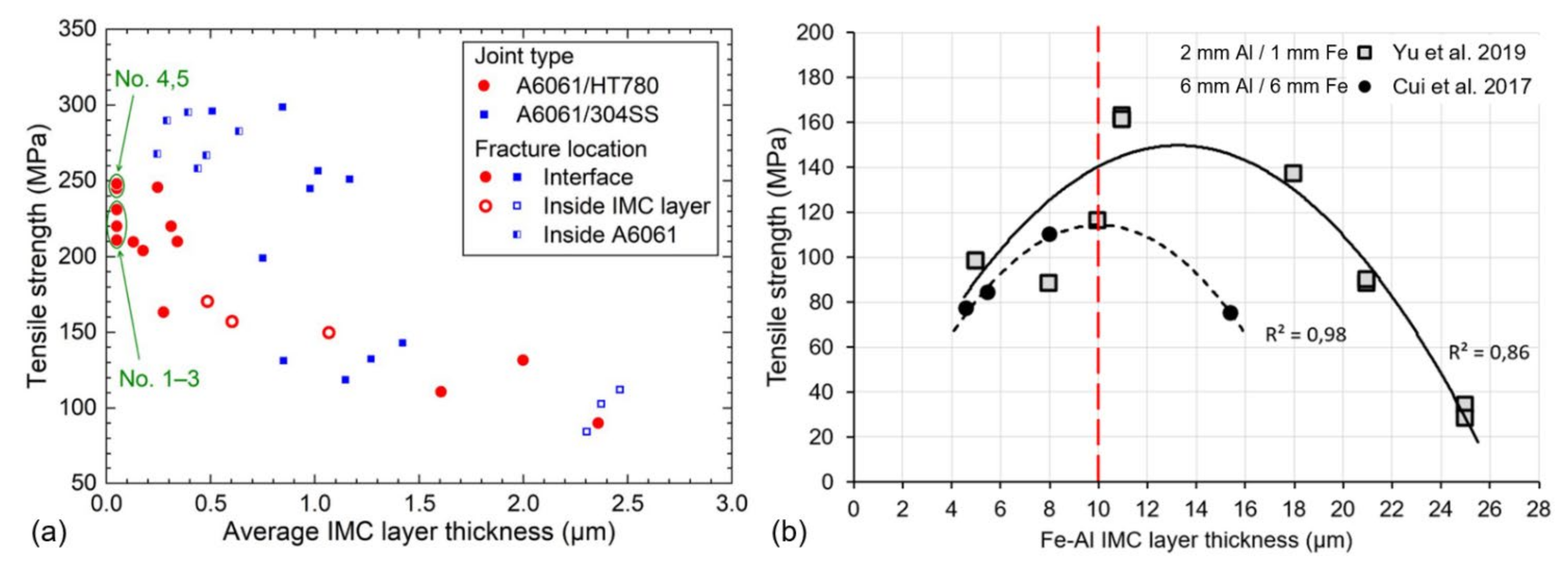
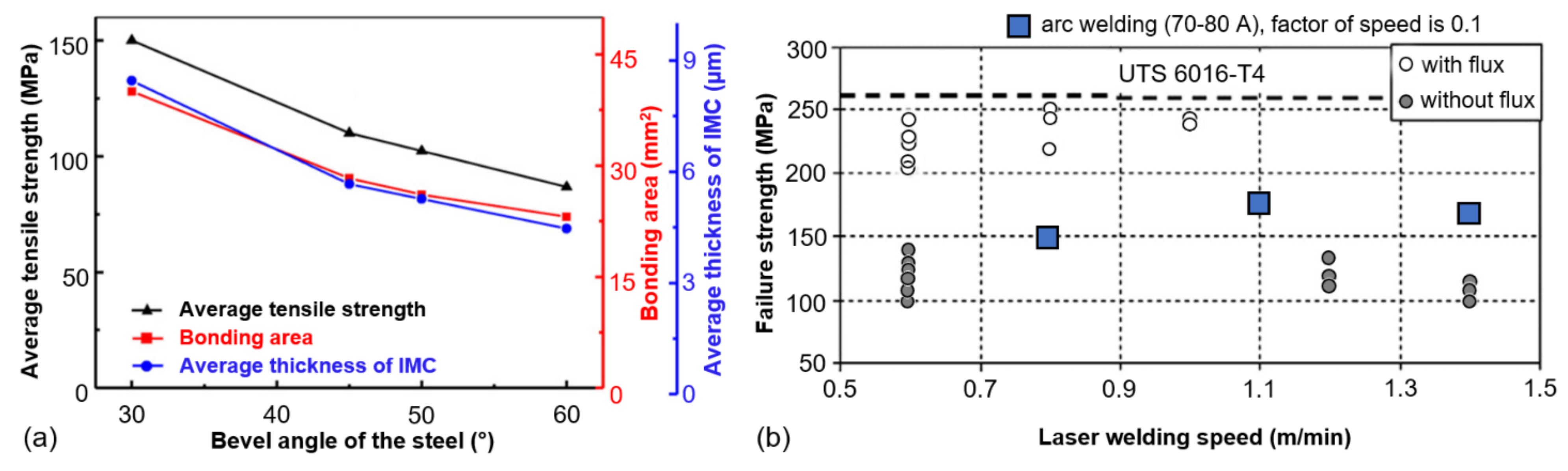
Figure 1c) between dissimilar metals, which is sometimes referred to as the reaction layer or the intermediate layer. The mechanical properties of the IMC layer are mainly dependent of the composition and thickness, which are highly dependent on heat input. It is known that >10 µm IMC thickness is harmful for mechanical properties in the case of steel to Al welding [
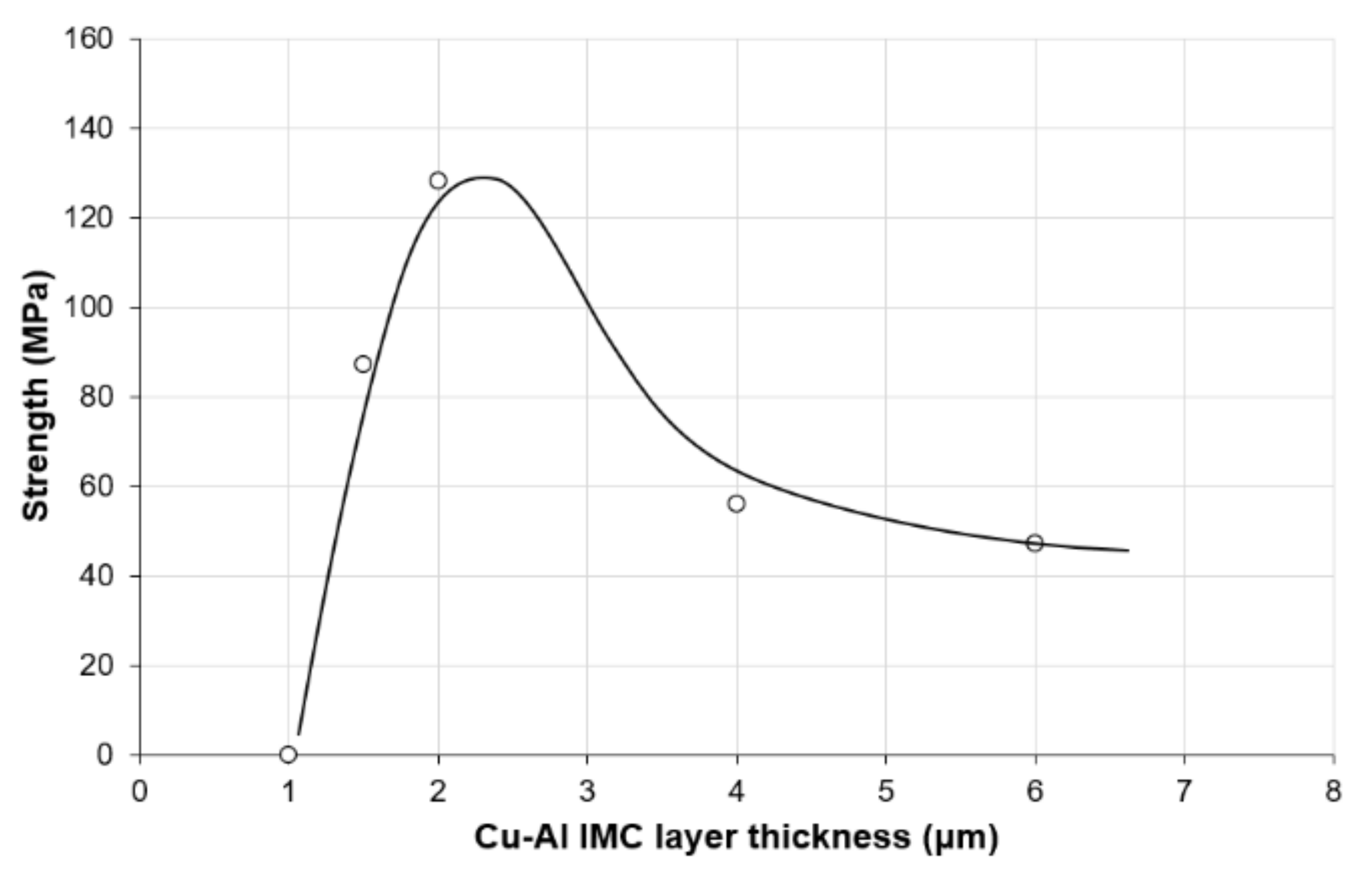
5]; being too thin may lead to poor bonding strength [6,7] (see Figure 1d). Therefore, the heat input must be lower and strictly controlled; the choice of the welding process (arc, laser beam, and resistance) can significantly determine the quality of the joint. In addition, based on the selected welding process, geometrical weld pool parameters also contribute to the final quality of welded joint. Here, laser beam welding (LBW) is an excellent alternative to traditional resistance spot and arc welding. LBW offers much higher productivity, due to having more concentrated energy, easily melting highly conductive materials, and providing lower heat inputs, reducing the IMC layer thickness. Moreover, welds are narrower and may provide enhanced fatigue resistance. When filler wire is needed to enhance fusion zone properties with wider control of dilution, the laser-assisted arc welding process is another possibility.
During the thermal cycle, the kinetics of the IMC layer growth is mainly controlled by diffusion, and the diffusion coefficient (denoted as D with dimension of m2 s−1) can be estimated, according to the Arrhenius equation based on Fick’s law of diffusion as follows [5,8,9]:
D = D 0 e x p Q R T ln D = ln D 0 Q R T
where D0 is the pre-exponential factor (m2 s−1), Q is the activation energy for the growth of the interfacial IMC layer (J mol−1), T is absolute temperature (K), and R is the gas constant (8.31446 J mol−1 K−1).
Figure 1. (a) Typical application of dissimilar materials in various industries, where Audi A8 is presented as an example and (b) battery pack made of cylindrical cells; modified and based on [10,11]. (c) Typical outlook and features of IMC layer by scanning electron microscope, from [7]. (d) Effect of IMC layer thickness on strength [6,7].
Metals 11 01680 g001
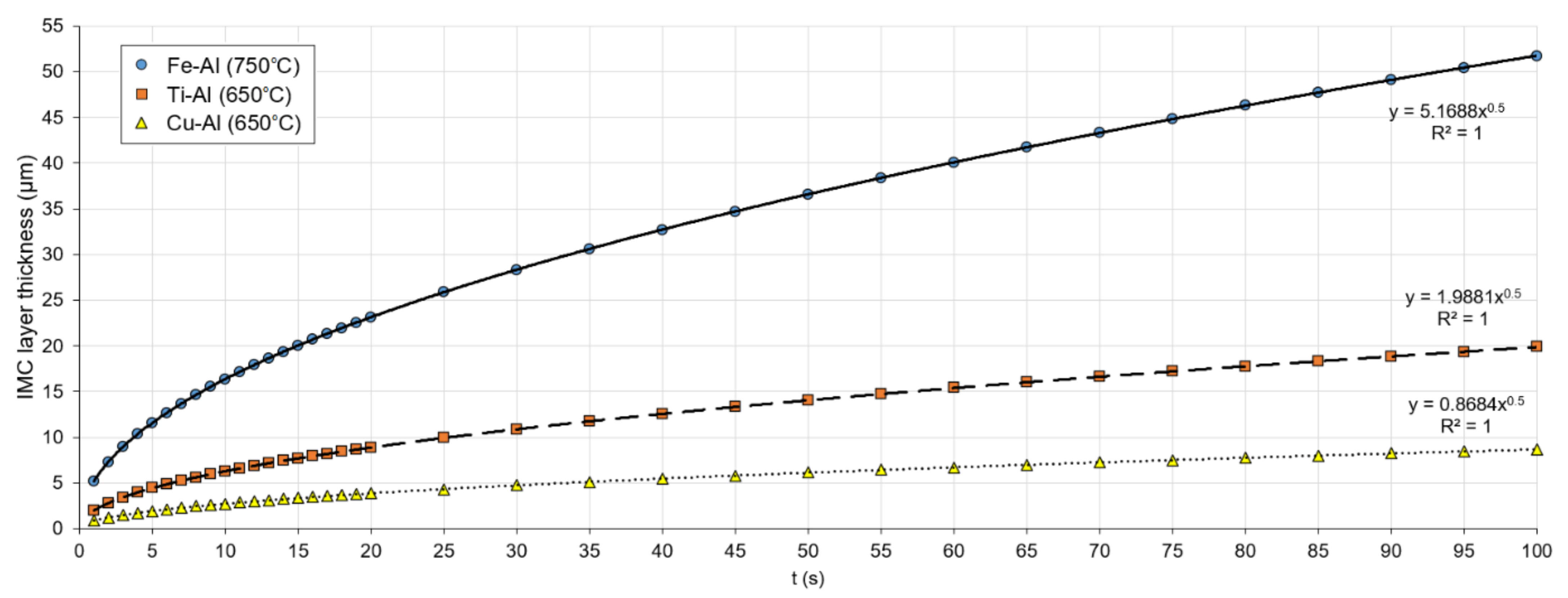
It was shown that the Fe–Al IMC layer growth has a linear relationship with the square root of diffusion time (t), representing the parabolic rate law with the kinetic exponent (n ≈ 0.5 for diffusion-controlled growth and n = 0.9–1.0 for reaction-controlled growth). The thickness of the diffusion layer (denoted as dIMC) can be estimated by the following equation [5,9]:
d I M C = D t n = D · t ln   d I M C = ln D + n ln t
The presented Equation (1) is applicable for atom diffusion in solids (solid/solid), which is driven by several mechanisms. For the welding case, diffusion includes also the liquid state (solid/liquid), which is far more complex [8]. However, the Arrhenius equation is still valid and was shown by Springer et al. [9] for the Al–Fe case. In the case of overlap LBW joints, Fan et al. [12] showed deviation in the calculated IMC layer thickness by using the Arrhenius equation when compared with measured values. The calculated values provided two to three times increased thicknesses. However, both obey parabolic law. The authors claimed that there may be the wrong selection of diffusion parameters (D0 and Q) since they are defined experimentally, and the exclusion of more complex phenomena, such as phase transformation and dissolution. This may also be linked to which element diffusion controls the reaction rate: either self-diffusion of Al to the interface towards the first intermetallic phase formed, or Fe diffusion into the phase formed.
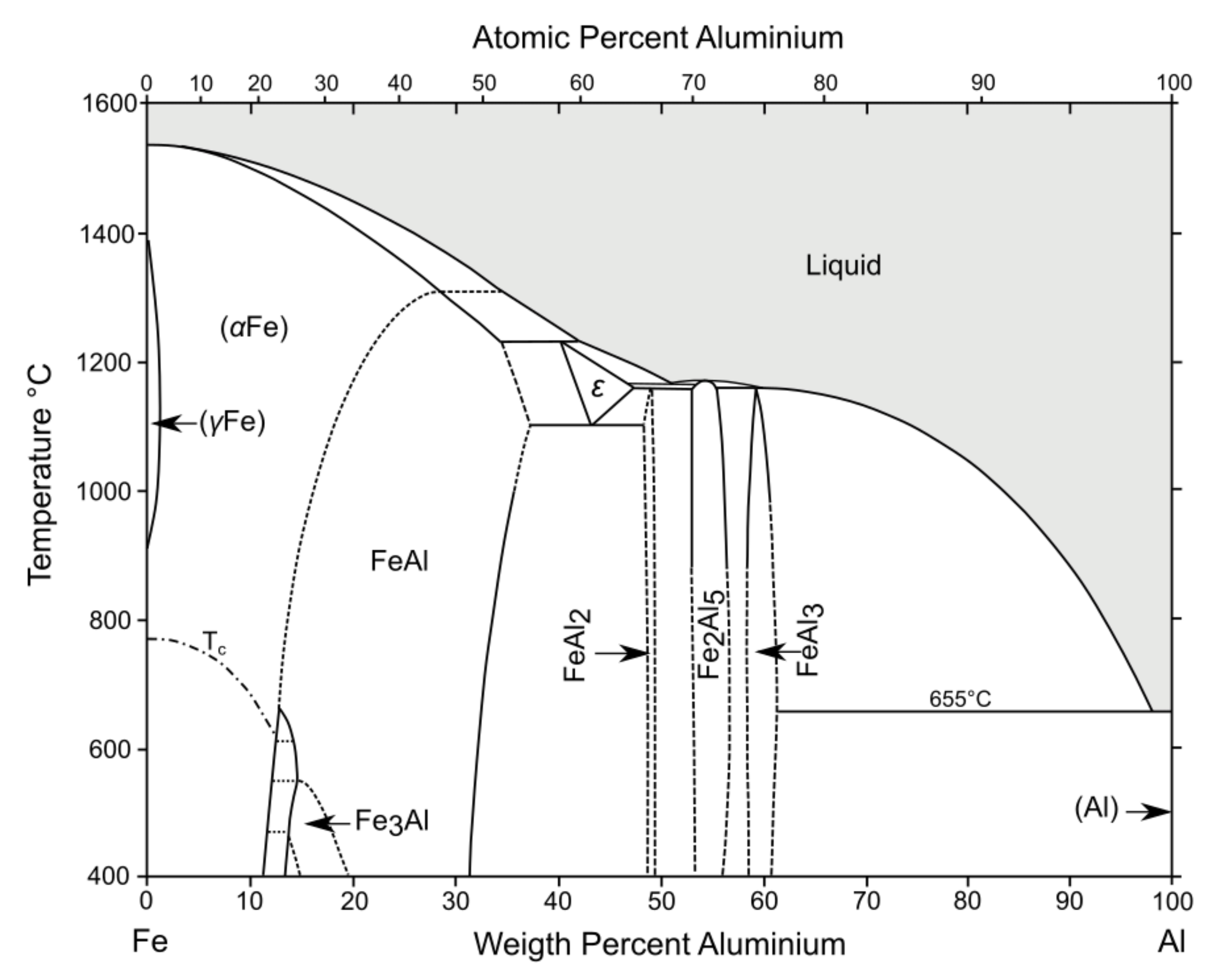
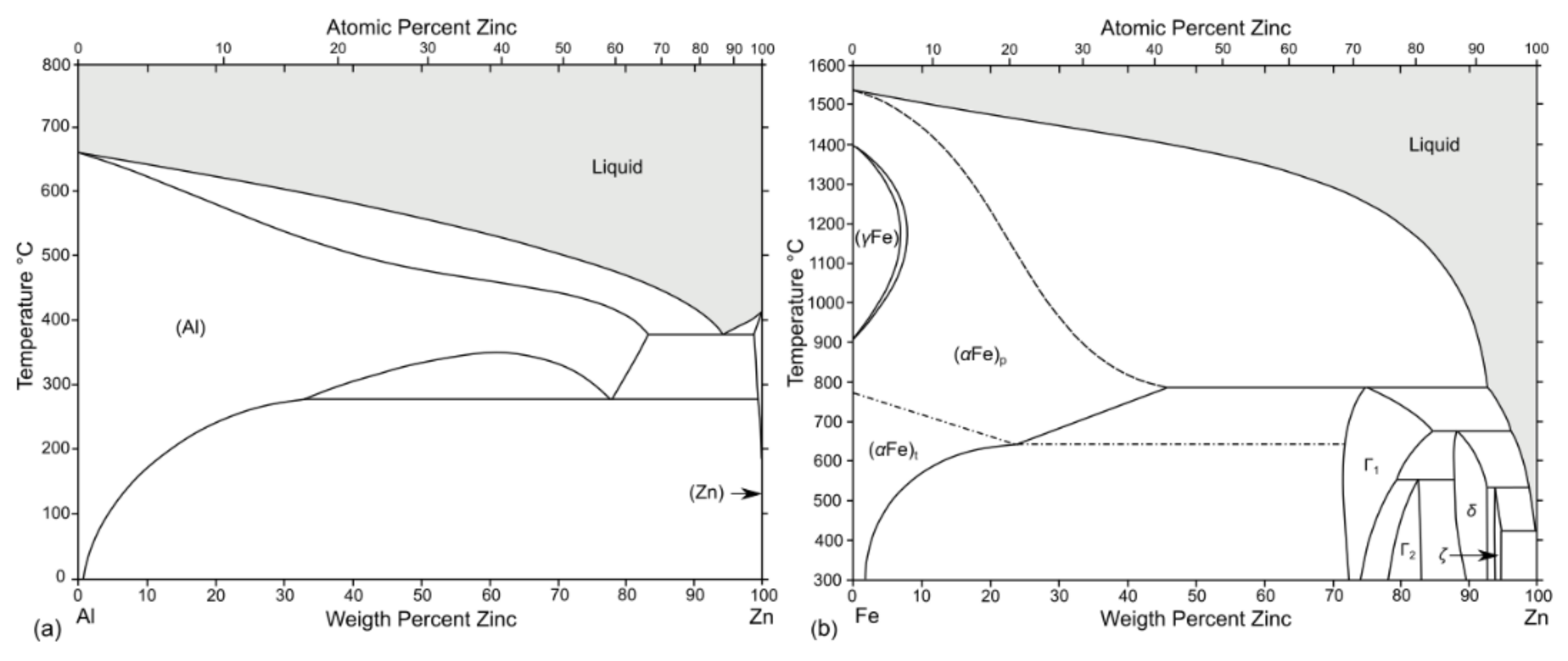
The application of Equation (2) for Fe–Al/Ti–Al/Cu–Al is shown in Figure 2. For the Fe–Al case, the development of the Fe2Al5 phase is assumed since it is the predominant phase (see Section 5.1). The phase growth parameters at 750 °C are taken for calculations as follows: D0 = 53×10−4 m2 s−1 [5] (iron atom diffusion in Al) and Q = 210 kJ mol−1 [13]. The IMC layer growth follows the parabolic law. At higher reaction temperatures and time, it may disobey the parabolic law and obey the linear increase. The applicability of Equation (2) showed also good agreement for the Ti–Al case [14] (using D0 = 21 × 10−4 m2 s−1 and Q = 296 kJ·mol
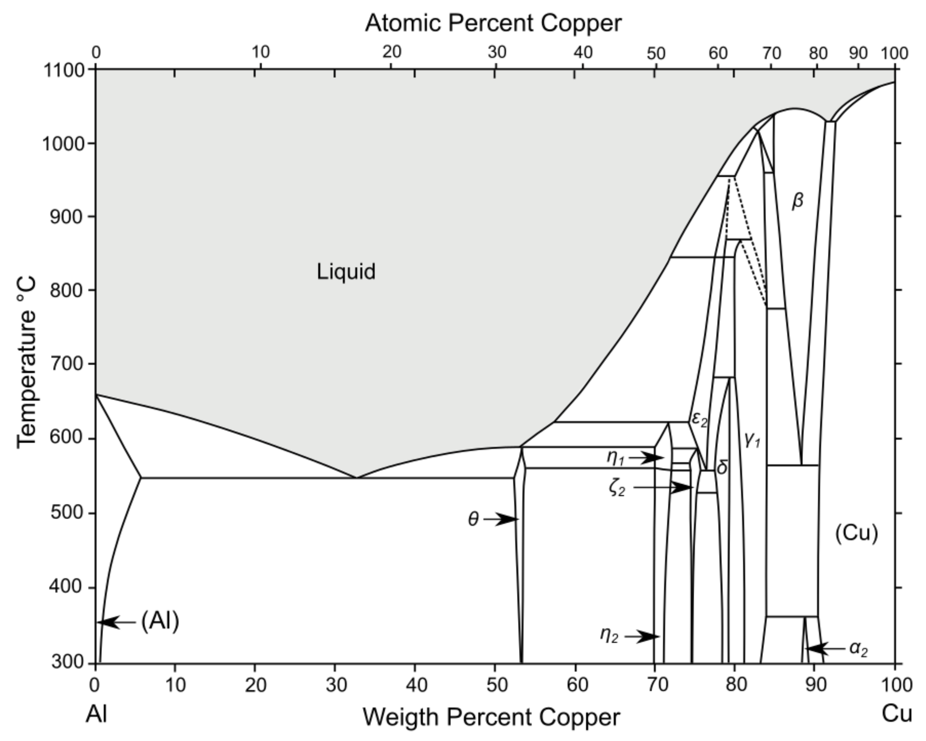
−1 at 650 °C) and for the Cu–Al case [15,16,17] (using D0 = 8.8 × 10⁻⁴ m2 s−1 and Q = 72 kJ·mol−1 at 650 °C). Note that the linear relationship can also be shown by taking the natural logarithm (ln) of both sides in Equations (1) and (2) and strongly depends on the temperature and the D0 parameter.
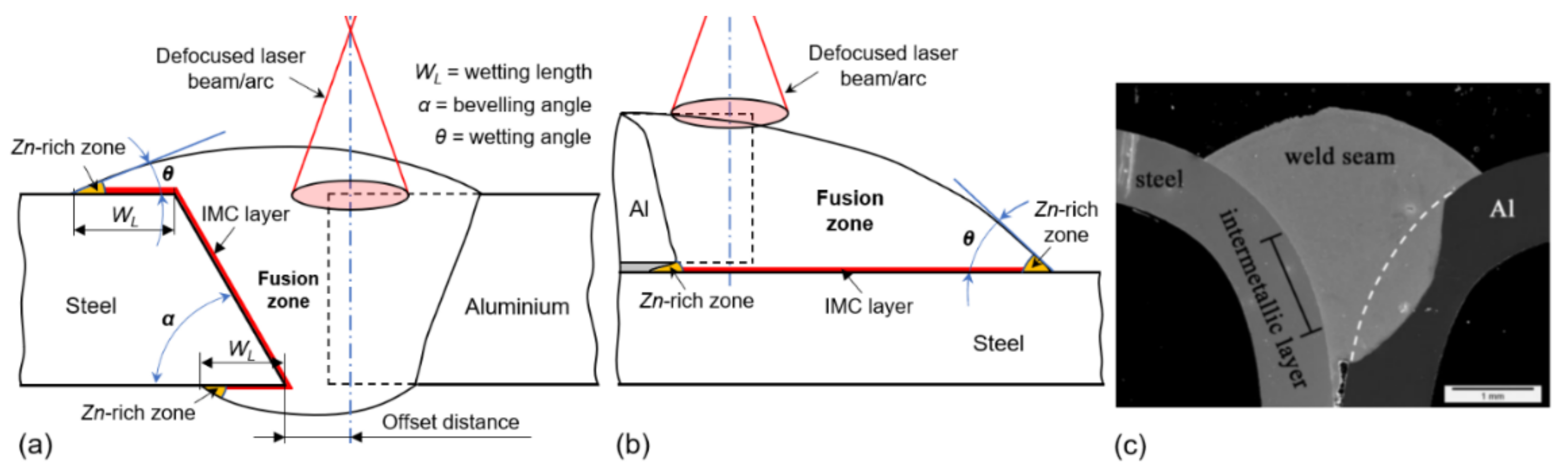
The wettability and wetting angle are important factors in dissimilar materials welding, especially in the case of lap or corner joint types. It depends on surface tension during solidification, and the energy balance can be calculated based on Young’s equation [18,19]:
c o s θ a = σ s v σ s l σ l v
where θa is the contact angle between liquid and solid (wetting angle), σsv is the interfacial free energy or surface tension of the solid–vapour; σsl is the solid–liquid, and σlv is the liquid–vapour interfaces, respectively. Note that θa has a significant effect on joint strength and will be presented later in relevant sections.
In order to obtain the liquid metal spreading, the following requirement, Equation (4), and condition, Equation (5), must be satisfied [19]:
σ s l < σ s v σ l v c o s θ a
σ l v < σ s v
In this work, a comprehensive review is focused on the laser beam and laser-assisted welding of Al–Fe, Al–Cu and Al–Ti, due to the high relevance to industrial applications. The scope of the review includes understanding thermophysical properties and laser beam absorption principles, fundamentals of laser beam and laser-assisted arc welding physics, metallurgical studies of steel to aluminium, galvanised steel to aluminium, copper to aluminium, and titanium to aluminium welding-brazing fundamentals. The latest development in the welding of these alloys is presented, including an in-depth metallurgical analysis.

2. Fundamentals of Laser Beam Welding

Laser beam welding has high potential in joining dissimilar metals. LBW may be suitable for highly conductive materials, due to high concentrated energy for melting. A laser beam is a non-contact flexible tool, and the power intensity distribution can be changed for specific purposes with enhanced productivity [2]. Low heat input provides a narrower heat-affected zone (HAZ), and thus, the strength may be enhanced. Laser beams may operate under two essential temporal modes, continuous wave (CW) and pulsed wave (PW) [20]. Modern laser beams have highly customisable pulsing capabilities with a pulse duration in the order of µs, very high peak powers in the order of megawatts, and complex pulse shapes with frequencies that greatly surpass that of pulsed arc welding. LBW is normally carried out without filler wire, especially for thinner sheets, and is mainly used in the automotive and aerospace industry. Addition of the filler wire can be complicated and requires tedious optimisation, especially for thin sheets [21,
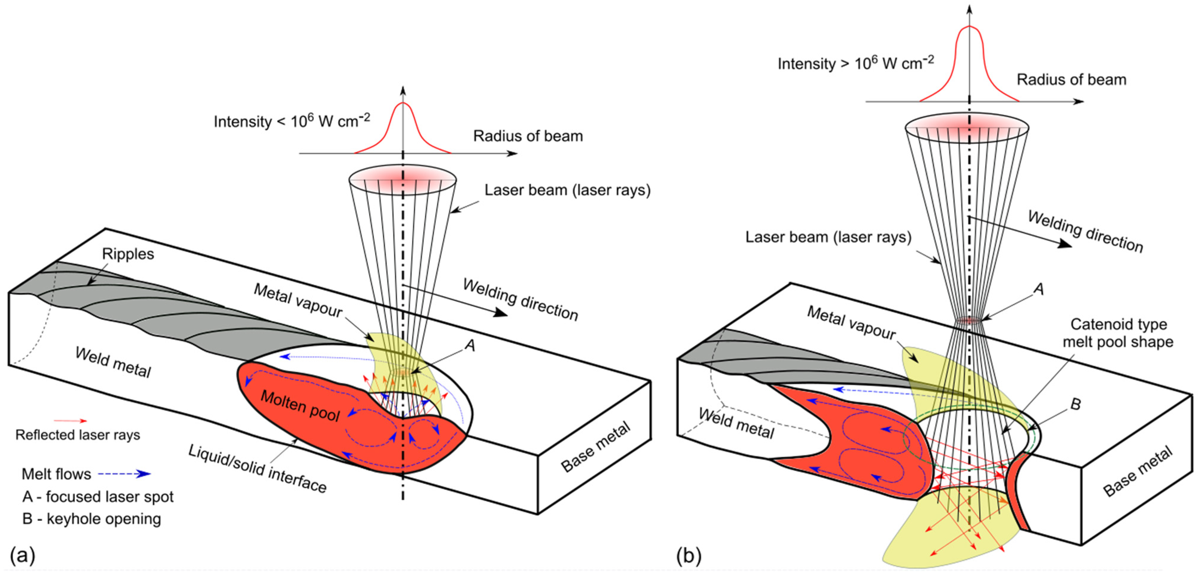
22]. Heat conduction laser welding usually operates under <106 W/cm2 energy density (see Figure 3a) and is more often used for thin plates (<1 mm), where the energy should not be sufficient to generate a keyhole but high enough to melt the material locally. Here, the melt flows are very dependent on the active surface elements and are similar to the tungsten inert gas (TIG) process weld pool [23]. Higher energy density (>106 W/cm2) forms a keyhole, providing much higher penetration depths, due to multiple reflections (see Figure 3b) and increased absorption. The threshold for transition from the heat conduction mode and keyhole varies and mainly depends on the wavelength and surface conditions. Based on Behler et al. [24], Nd:YAG requires two times lower power density to generate a keyhole, and its drilling time is several times faster, compared to the CO2 laser. Similar is expected for the fiber/disk laser. There is also the transition mode between heat conduction and keyhole. Notably, the stability in the heat conduction mode is much higher than in the keyhole mode, due to a more stable weld pool with low porosity and spattering. The keyhole mode often has a spiking effect, as the keyhole collapses, causing porosity. Therefore, more optimisation of parameters is needed, but it is more attractive for thicker plates [25,26].
Due to the fast solidification speed, LBW may cause cracking, porosity, and poor metallurgical affinity in the fusion zone due to brittle phases. Microstructure in the fusion zone can be improved by using specific interlayers by coating components [27]. Disadvantages of LBW are high-cost investments, safety issues, high requirements of joint preparations of components to be joined, more complex process and variables to be adjusted, and lower wall plug (electrical) efficiency, compared to other processes.
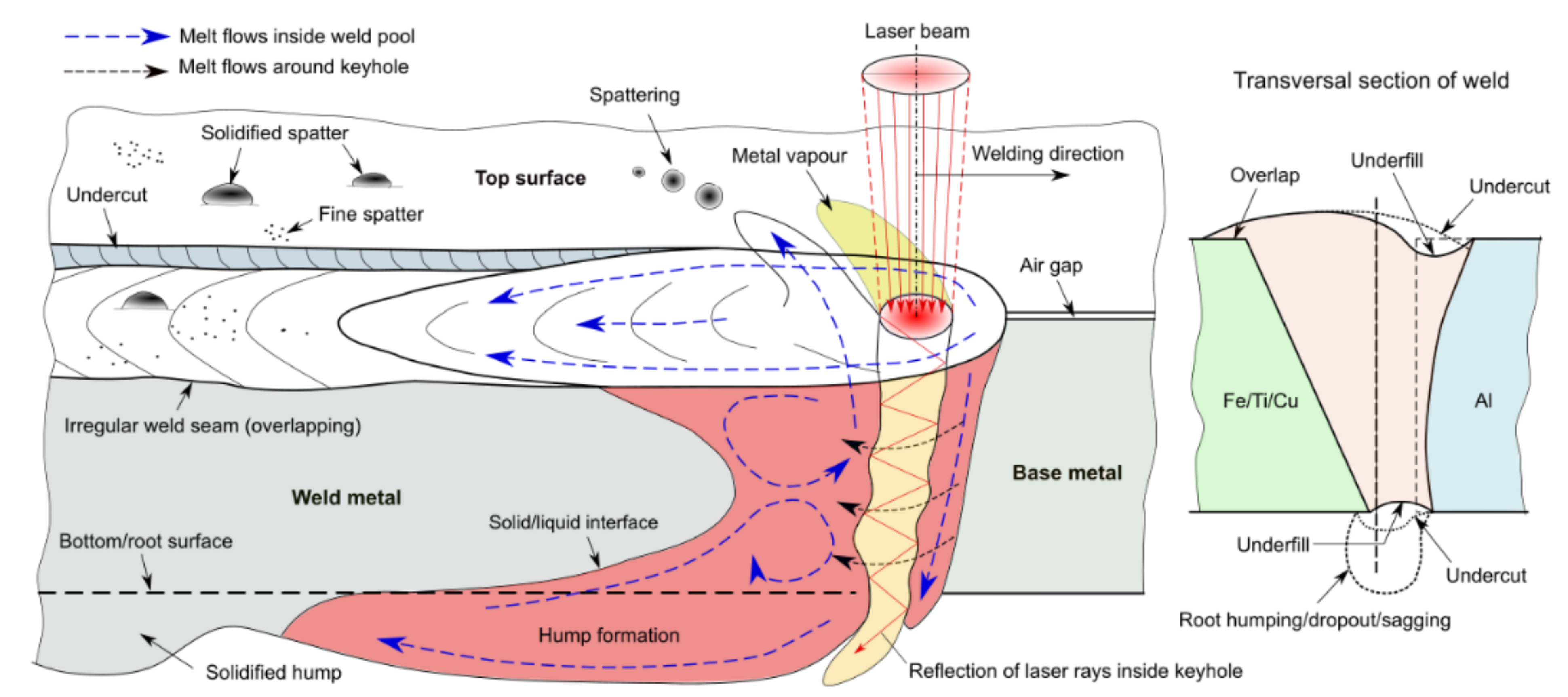
Poor appearance of weld bead and surface defects are frequent challenges in LBW, due to unstable melt pool formation, especially in the keyhole mode (see Figure 4). External weld seam defects are undercut and underfill (top and root), spattering, upper and root humping. The formation of undercuts, spattering and root humping are attributed to many factors, including process parameters, welding conditions, shielding gas composition, surface tension and viscosity of the used metals. International standards ISO 13919-1 [28] (for steel) and ISO 13919-2 [29] (for Al) specify the limits for different quality levels. Detailed information concerning various external weld pool defects and mechanisms can be found in [30].
Figure 3. (a) Schematic illustration of laser beam physics (beam focused near surface) during heat conduction mode with melt flows based on [31,32]. (b) Schematic drawing of laser beam physics (defocused beam) during keyhole mode welding [21,22,33].
Metals 11 01680 g003

3. Thermophysical Properties of Different Metals and Laser Beam Absorption

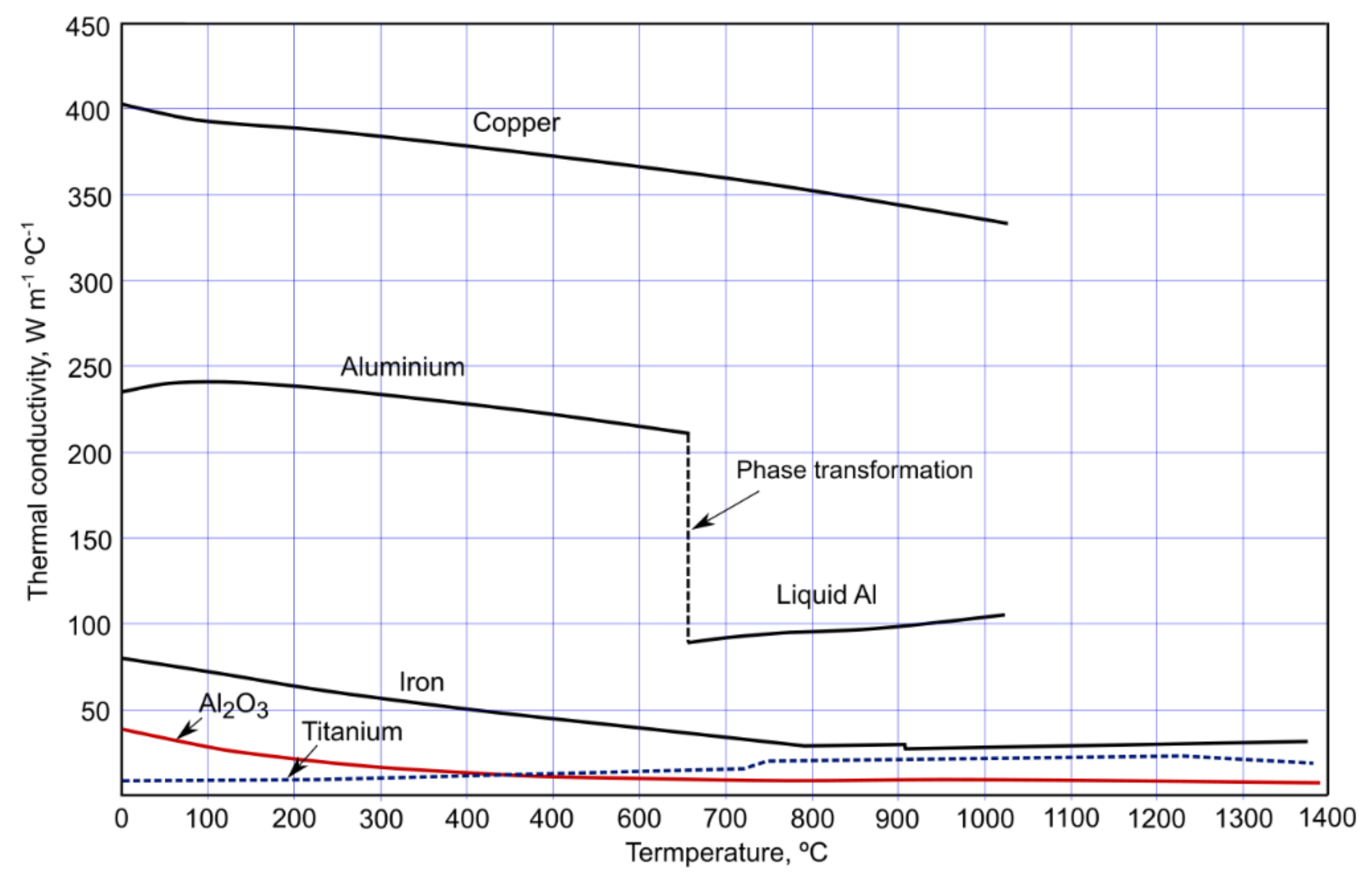
Aluminium alloys are widely used, due to their low weight and corrosion resistance. Al alloys possess high thermal conductivity requiring higher energy for melting, similar to Cu. A comparison of aluminium to other metals in terms of thermal conductivity versus temperature is shown in Figure 5. For aluminium, the thermal conductivity decreases with increasing temperature in solid and drops significantly at phase transformation stage. Oxide film (Al2O3), which naturally occurs at the surface, has much lower conductivity with a constant decrease with the temperature. Al has low melting point (660 °C), compared with many metals and its alloying elements, except Zn and Mg as shown in Table 1. However, on the surface, the Al2O3 film is inevitable formed and has a much higher melting point (~2050 °C); thus, additional removal of the oxides is required (e.g., mechanical or chemical cleaning). This oxide layer can be removed by applying fluxes or mechanically by a stainless-steel brush prior to welding. The TIG process with DCEN (direct current electrode negative) provides the cathodic cleaning effect by removing surface oxides through ions with high kinetic energy [54]. A rapid change in the thermophysical properties (except surface tension) of pure Al occurs at 660 °C, due to the transition from solid to liquid. Another important issue is the high difference in thermal expansion between Al/Cu alloys and carbon steels/Ti, 2.0−2.4 × 10⁻⁵ m·m−1−1 and 0.8−1.2 × 10⁻⁵ m·m−1 °C−1, respectively, which may lead to high distortions and residual stresses [55]. The solubility of alloying elements in Al/Fe as an important metallurgical factor is indicated in Table 1. Metals may have high solubility in each other, forming a homogenous substitutional solid solution when the atomic size is within 15% of Al, with a similar crystal structure, the same valency, and similar electronegativity, according to the Hume–Rothery rules [56].
Table 1. Thermophysical properties of different metals [57,58,59]. Solubility values are maximum possible values usually achieved at high temperatures (e.g., >700 °C). Face-centred cubic denoted as f.c.c., body-centred cubic as b.c.c, and hexagonal close-packed as h.c.p. crystal structures. Note, Si has complex face-centred diamond cubic crystal structure (*). Indicated valency (+) values are most common. χ is electronegativity by Pauling scale.
ElementMelting Point, °CBoiling Point, °CSolubility in Al, wt.%Solubility in Fe, wt.%Crystal StructureAtomic Radius, pmValencyχDensity, g/cm3
Al6602467negligiblef.c.c.11831.612.7
Mg649109017.4negligibleh.c.p.14521.311.7
Mn124419621.82negligibleb.c.c.1612, 4, 71.557.3
Cu108325675.65negligiblef.c.c.1451, 21.908.9
Si141023551.65negligiblef.c.c. *11141.902.7
Zn42090766.4negligibleh.c.p.14221.657.1
Fe153527500.04b.c.c.1562, 31.837.9
Cr185726720.77<4.0b.c.c.1662, 3, 61.667.1
Ni145327320.04<3.0f.c.c.14921.918.9
Ti166032871.32negligibleh.c.p.1762, 3, 41.544.5
Figure 5. Thermal conductivity changes with temperature of different metals. Redrawn from [60].
Metals 11 01680 g005
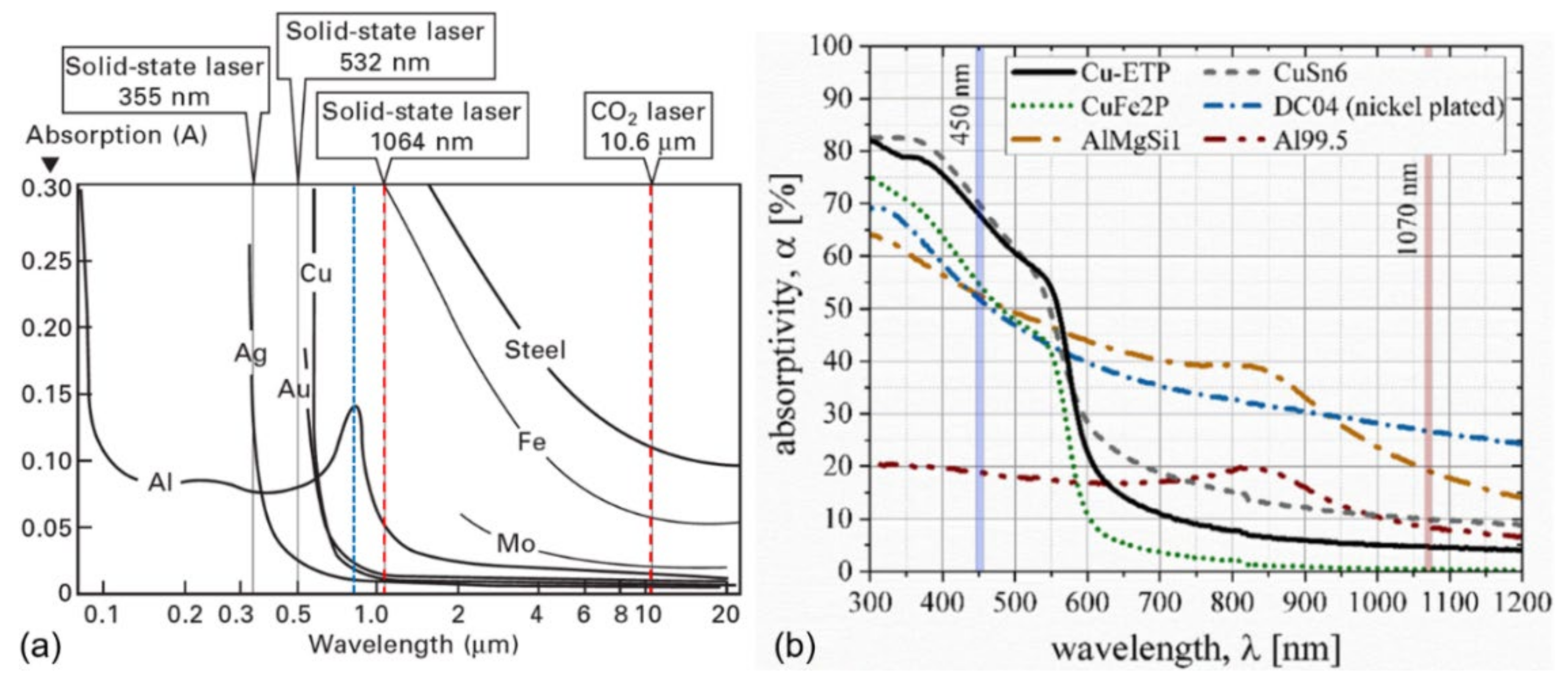
Reflectivity and the associated absorption of the electromagnetic wave, the laser ray, during laser–matter interaction is an important phenomenon. A general overview of the absorption coefficient of different metals in a wide spectrum [61] is shown in Figure 6a. Note that this graph does not consider the incident laser power level and its angle, surface condition, welding speed and other process parameters. Therefore, this graph is often under update and mostly applicable for general understanding. Moreover, each alloy has a specific chemical composition and provides slightly different temperature-dependent absorption coefficients. Generally, Al alloys (and Cu alloys) have much higher reflectivity, compared to steel, especially for long wavelength lasers, such as CO2 laser; thus, lower absorption is expected. The most widely used is the ytterbium fibre/disc laser, due to its high-power scalability and short wavelength of 1030–1070 nm. Infrared diode lasers (λ ≈ 820 nm) provide higher absorption and can be increased at a shorter wavelength [62]. Emission of 450 nm wavelength (a blue laser) is preferable for highly reflective metals and proven on the industrial scale [63,64] (see Figure 6b). These lasers can be produced up to 2.0 kW, which is enough to weld more than 1 mm thick Cu. However, they have high beam parameter product (BPP), meaning lower quality of the beam, but it is enough to perform heat conduction mode laser welding.
The actual absorption measurement is complicated and few research works have been conducted. At the stationary condition, 70% of absorption (at 3.2 kW) was obtained during Nd:YAG laser (1064 nm) keyhole welding of AA1xxx [65]. The absorption of Yb:fiber laser power from 2 to 10 kW increased from 56 to 84%, respectively, during LBW of AA5052 [66]. Moreover, the absorption was reduced (to 72%) by increasing the welding speeds. Miyagi et al. [67] reported the absorption of 50–55% during Yb:fiber laser welding in a wide range of different Al alloys. Absorption may be significant improved by using power modulation as well instead of the CW mode [68]. In the case of the heat conduction mode and high Mg content, improved absorption can be achieved [69], especially with longer pulse durations in PW mode. Absorption may be also improved by modifying the surface conditions, e.g., a chemically etched or anodised surface provides high absorption [31]. Due to constant reflection by the surface, the absorption during heat conduction mode of LBW is reduced, e.g., only 23% was obtained in the case of AA5182 [31]. Titanium alloys have reflectivity similar to steel, which also strongly depends on the laser wavelength. Lisiecki [70] measured absorption of 52% for a polished Ti surface and up to 72% for as-received (with oxide layer), using a high-power diode laser (λ = 808 nm) at 0.8–1.8 kW power range and 0.2–0.8 m/min scanning speed, similar to welding.

4. Laser-Assisted Welding and Brazing for Dissimilar Metals

In laser-assisted welding, the laser is frequently combined with an arc source or other joining methods. It is then defined as hybrid welding, but it may be not the same as laser–arc hybrid welding (LAHW), where high power laser beam is used to achieve very high penetration depth and the arc is mainly used as an additional heat source to add filler metal to the fusion zone [71]. In the case of laser-assisted welding, the laser beam may be used for preheating, stabilisation of the arc process (providing high quality of the joint), and/or enhanced penetration depth for increased productivity.
The typical setup of the laser-assisted joining process is shown in Figure 7a for thin sheets [72] and LBW with the keyhole mode in Figure 7b. A typical butt joint configuration and important parameters are shown in Figure 8a. When galvanised steel is used, there is a frequent accumulation of Zn-rich zones at the edge of the fusion zones (or weld toes), due to the low density of aluminium and higher electron affinity of Al–Fe compared to Al–Zn/Fe–Zn, which attract Zn atoms to these regions based on the work of Jia et al. [73] and Zhou and Lin [18]. Other typical joints are lap (overlap) joint (Figure 8b) and flange joint (Figure 8c). Due to the high differences in melting points of the two metals (for the case of Al, see Section 3), an aluminium alloy with a much lower melting point is fully melted, whereas steel is only partially melted. Therefore, the process can be termed as laser-assisted brazing with the possible application of fluxes for improved wettability, enhancing bonding. The location of the heat source is an important process parameter since it is usually not located in the groove between plates but has an offset from the interface toward the base metal. Frequently, the heat source (laser beam and/or arc) is located on the aluminium side [7,42,74,75,76,77,78] (as indicated in Figure 7a) to minimize the melting of high melting point metal (steel, Cu, Ti) to reduce harmful intermetallic compounds. In addition, the thickness of the IMC layer is uneven across the bonding area [53]. A thicker IMC layer is formed on the top surface of the joint, due to higher heat accumulation, compared to the root side. Moreover, the IMC layer at the root can be so thin that it has low metallurgical bonding. The average IMC thickness values are based on the layer present on the groove side. In the case of deep penetration LBW of thicker sheets (>2–3 mm), the laser beam may be located on the steel/Cu/Ti side to melt both metals (Figure 7b) [79,80]. These differences and their effects are presented in the following sections.

5. Steel-Aluminium Welding–Brazing

Steel to aluminium (Fe–Al) joining is widely used nowadays and frequently studied. The difference in the thermal conductivity of these two metals (see Figure 2) is large, the ratio is about 1:5–1:9, depending on the alloys used; the melting point difference is by the factor of 2.2 (see Table 1). This implies that upon solidification, cracking and tearing may occur. Formation and growth of the Fe–Al IMC layer is complex. Therefore, optimisation of the heat input is more intricate in such cases, requiring in-depth studies.

5.1. Formation and Growth of Fe–Al IMC Layer

In the welding of Fe–Al, complex metallurgical reactions take place at the interface. Brittle Al-rich intermetallic compounds are formed, due to low mutual solubility; atomic radius, valency, and crystal structure of Al and Fe differ significantly, providing no possibility to form a homogenous solid solution. Both Al and steel have cubic crystal structure, and thus, substitutional diffusion is possible when Al atoms replace Fe atoms within the lattice at sufficiently high temperatures, typically in the range of 600–650 °C [5]. In this interlayer, large amounts of different IMCs (iron aluminides) are developed, and subsequently, they may deteriorate the mechanical properties [87]. The binary Fe–Al diagram was proposed by Kattner and Burton in 1992 [88] and is presented in Figure 9. The diagram is often revised, and modified versions are available now [89,90]. The most common IMCs are Fe3Al, FeAl, FeAl2, Fe2Al5, and FeAl3 [91,92] after welding. Recent studies showed that Fe4Al13 (θ) is more often recognised than FeAl3 [93]. The detailed overview of Fe–Al characteristics is provided in Table 2. Based on the hardness values, the most brittle phases with low plasticity are FeAl2 (ζ), Fe2Al5 (η), and FeAl3 (θ). It is expected that cracking and fracture during mechanical strength testing can be generated and propagated through these phases. Therefore, these phases and the total layer thickness should be minimised as much as possible. However, in using conventional arc welding with high heat input, it is challenging to achieve the thin Fe–Al IMC layer. Here, LBW provides advantages of a lower heat input. Low wettability of molten Al on solid steel is another challenge in welding–brazing. The zinc-coated steel is an alternative solution since it provides significant enhance in wetting distances (see Section 5.5).
Based on the work by Agudo et al. [83], where a relatively new CMT (cold metal transfer mode, Fronius GmbH) process was used with low heat input, a very thin IMC layer was formed (2.3 µm), consisting of Fe2Al5 and FeAl3 phases. Both have low symmetry lattices, orthorhombic and monoclinic, which provide low ductility and toughness. Torkamany et al. [94] identified the gradient distribution of FexAly phases during laser-pulsed welding in lap joints (steel was on top of Al). Fe-rich phases (FeAl and Fe3Al) were identified close to the welding surface, and more complex Al-rich phases were located in the bottom interface. Fe-rich phases are not easily formed, due to their lower kinetic coefficient [5]; thus, they are easier formed at higher heat inputs. Since FeXAly phases have significantly different thermal expansion coefficients and high hardness, they are the cause of cracking during solidification.
Li et al. [98] identified the plasticity of different phases. Fe3Al and FeAl2 are found to exert plastic deformation. This is probably linked to their higher lattice symmetry with b.c.c. and triclinic lattices. FeAl, Fe2Al5, FeAl3, and Fe4Al13 provide brittle fracture. However, according to Kobayashi and Yakou [5], the FeAl phase tends to be the ductile phase. They proposed the plasticity ranking (from high to low) as follows [98]: Fe3Al (high plasticity) > FeAl2 > FeAl3 > Fe2Al5 > Fe4Al13 > FeAl (brittle).
The formation of a specific θ phase (Fe4Al13) in welds is also common but challenging to identify. In keyhole LBW of 6 mm plates, Cui et al. [79] indicated θ-phase formation as a needle-like island on the Al side and serrated θ-phase close to the interface, consisting of the Fe2Al5 phase layer. Due to the deep weld, inhomogeneous distribution of the IMC layer was developed, with the θ phase predominantly formed in the upper part. Similar results of a detached and needle-like (or acicular) Fe4Al13 phase was shown by Cao et al. [44] during high heat input welding of 2 mm AA5052 and press-hardened steel.
The formation and growth of the Fe-Al IMC layer during welding is schematically shown in Figure 10 [7,9,13,43,44,79,80,85,99,100,101]. The IMC layer is a diffusion-driven phenomenon [5] since the thickness of IMC layer is a function of time where Fe atoms diffuse into the IMC layer. The diffusion coefficient of Fe in Al is ~30 times higher than Al in Fe [5]. Initially, while Al is in a molten/mushy state and the time range depends on thermal cycle, it covers the steel surface, and FeAl and/or FeAl3 are formed at the interface due to the interdiffusion of Al/Fe atoms [5]. At the same time, Fe2Al5 is formed and grows toward the steel in the preferable [1] direction, having a tongue-like morphology. Further growth is controlled by the heat input and cooling conditions. At higher reaction temperatures (>950–1000 °C) the Fe2Al5 becomes more flat in shape (as visualised in Figure 10), and its thickness reduces, while on the Al side, a substantial amount of island-like phases are formed with cracking at the liquid Al/FexAly interface [101]. Therefore, heat input during welding should be strictly controlled.
The Fe2Al5 phase is considered the most dominant phase, and its thickness is substantially larger than any other phase, at up to 85–90% of the total IMC layer thickness depending on parameters and conditions [93,101,102]. The mechanisms of the IMC layer generation are similar to the hot dipping process or steel aluminisation during immersion in molten aluminium [5,102]. Frequently, Al+FeAl3 eutectics can be found toward the Al side, with various detached islands or free phases (FeAl3/Fe4Al13), especially at high weld heat input. The thickness of Al eutectics is larger (20–70 μm) than the reaction layer but is more ductile and usually is not of concern. Notably, the thickness of IMC layer may vary significantly over the length and depends on the area in the joint.

5.2. The Effect of Filler Wire on Fe–Al IMC Layer

The selection of filler wire has a significant effect on the Fe–Al IMC layer; silicon has a profound effect. Filler wire with high Si content may reduce the diffusion of iron in molten Al [13], reducing the IMC layer thickness, specifically the Fe2Al5 phase. Springer et al. [9] identified 11 phases (τ-phases) during molten and semi-solid (mushy) Al interaction with solid Fe. Particularly important were the τ6 (monoclinic Al4.5FeSi, only relevant at high temperatures) and τ5 (hexagonal Al8Fe2Si) phases, which inhibit the growth of the Fe2Al5 phase along its c-axis, due to structural vacancies and being filled by Si atoms. However, with a further increase in the Si content (from 1–2 wt.% to 5 wt.%), the thickness of the IMC layer grew. Therefore, excessive Si content in the filler wire may be adverse in arresting the Fe2Al5 phase growth; thus, the Si content should be optimised.
Song et al. [103] studied the effect of filler wire with different Si content, using TIG welding–brazing. Si-rich filler material (5 wt.%) successfully prevented IMC growth, compared to pure Al wire. The wire alloyed with 12 wt.% Si provided slightly thicker IMC layer than in the case with 5 wt.% Si wire. With the addition of Si, needle-like shaped IMCs (FeAl3) were changed to a plate-like continuous FexAlx layer with the formation of τ5 in the top layer. The effect of the Si content on the IMC layer morphology is shown in Figure 11a–c with crack path positions. Xia et al. [99] applied LBW with similar filler wires and found that with increasing the Si content (12 wt.% Si wire), the IMC layer thickness was significantly reduced. Moreover, the addition of Si prevented microcracking in the IMC layer (see Figure 11d–f). However, filler wire with 5 wt.% Si provided the highest tensile strength with a thicker IMC layer. The Si addition affected the FexAlx phases, the FeAl3 phases transformed to Fe(Al,Si)3 and Fe2Al5 to Fe2(Al,Si)5. However, it did not suppress the IMC layer growth. The reason for 5 wt.% Si wire having better ductility is that it contained more Fe2(Al,Si)5 phases, which have higher plasticity, whereas the 12 wt.% Si wire had only brittle τ5 and Fe(Al,Si)3 phases.
Zinc-based filler wire may also be used for non-galvanised steel-to-Al alloy welding. High addition of Zn changes the composition of the IMC layer toward Zn-rich phases such as η-Fe2Al5Zn0.4 and δ-FeZn10 [81], instead of Al-rich phases. Zn is highly soluble in Al; thus, it does not form Al–Zn intermetallics. According to Tan et al. [81], the filler wire with higher Al fraction (lower wt.% of Zn) provided higher strength, due to scattering and reduction in the brittle δ-FeZn10 phases and a thicker η-Fe2Al5Zn0.4 layer. This is an indication that, even though a thicker IMC layer was produced, higher strength can be achieved, due to more favourable phases, their amount, distribution, and morphology.

5.3. Effect of Process Parameters on Fe-Al IMC Layer and Mechanical Properties

The Fe–Al IMC layer thickness strongly affects the strength and ductility. However, there is no clear understanding of the underlying mechanisms since it may also depend on other process parameters and conditions. For FSW with low heat inputs, the critical thickness of 0.5–0.7 µm was identified [104,105], where, below this value, high tensile strength is achieved, comparable to base metal strength; see Figure 12a. With the IMC thickness of >0.7 µm, a sharp decrease in strength occurs [105]. In addition, the mismatch between different parent metals also plays a significant role since it affects principal distribution of stresses at the interface. This effect becomes more pronounced when steel and Al alloy have higher strength mismatch.
In fusion welding, the IMC layer tends to be frequently larger than 1.0 µm depending on the heat input. Therefore, the control of the heat input is constricted with typical thickness of the Fe–Al IMC layer, frequently >3 µm. In addition, the IMC layer is characterised by a large hardness spike (see Figure 13), due to the presence of various hard Fe–Al phases (see Table 2), which may lead to stress concentration and cracking. The hardness spike is similar for both thin (<2 mm) and thicker sheets (>3 mm). According to many studies [7,12,42,80,85,106], the growth of the IMC layer is linear with increase of the heat input, which is a function of the welding speed (e.g., lower welding speeds provide higher heat input), laser and arc power. This is reflected in Figure 14a. It seems that it does not follow the parabolic law of growth (presented in introduction), but welding is only within a specific range of temperatures and cooling; thus, more of the phenomena involved should be taken into consideration, such as convective heat. Higher heat input increases the cooling time and provides more time for diffusional growth of the IMC layer. Thus, the laser-based welding is more attractive than arc welding, due to lower heat inputs. However, higher heat input may increase the wetting distance since more material is melted to increase the tensile strength (will be discussed later). Too low heat input may provide lower strength, due to low wetting distances, an unfavourable wetting angle, and poor metallurgical integrity [47,75]. Moreover, due to a faster cooling rate, the hardness may increase, and cracking may be generated at the IMC layer. Therefore, the thermal cycle should be carefully considered and accordingly optimised.
Early studies indicated that the critical thickness of the IMC layer that is detrimental for mechanical properties is ~10 µm [9,107]; this is generally accepted. The results of laser-based welding are shown in Table 3 and shows that the highest strength is achievable within the range of 5–8 µm, depending on the different combinations of alloys and conditions. A clearer representation of the effect of the IMC layer thickness on strength was represented by Yu et al. [7] and Cui et al. [80]; see Figure 12b. It shows that the maximum strength may be achieved within the 11–12 µm thickness range and moderate heat inputs and seems applicable to a wide range of sheet thicknesses. Chen et al. [75] reported that optimal strength was achieved at moderate heat inputs and welding speeds in the butt joint of 2.0–2.5 mm thickness (steel/Al) sheets with laser–CMT hybrid welding. The strength was dependent on the spreading distance (see Figure 8) and wetting angle. The spreading distance decreased with higher laser powers and welding speeds, due to melt dropout, and as a consequence, the wetting angle increased. In such cases, increase in the wire feed rate is more effective in achieving improved wetting distances. However, additional heat input from arc should be strictly controlled since it directly affects the IMC layer growth. Similar results were achieved by Chen et al. [43] in welding 2.0 mm thick Q235 steel to AA5052 with the same process. Dharmendra et al. [6] showed that a larger wetting distance (L) and lower wetting angle (θ), represented by a ratio (L/θ), has a linear relationship with mechanical strength in laser welding–brazing of the galvanised steel to Al in the lap joint type; see Figure 15a. Notably, with an increase in the laser heat input, the wetting angle decreased linearly. Very thin IMC layer (<4 µm, see Figure 15b) provided lower strength, attributed to poor metallurgical bonding. A similar trend was reported by Yuan et al. [85] in the case of dual-beam laser-brazing lap joint of high strength DP590 steel (1.2 mm thick) and AA7075 (1.0 mm thick). Moreover, an increase in the heat input improved the wetting distance with higher tensile strength. Mathieu et al. [107] indicated that geometrical parameters (larger wetting distance and lower wetting angle) of the fusion zone had a significant effect on the strength of the joint, regardless of the IMC layer thickness, as long as it was below 10 µm. Another important factor was the effect of the IMC layer morphological features as discussed previously in Section 5.1. Dual spot beam welding, with cross-dual setup, may provide more uniform distribution of heat input and thermal gradients with increased mechanical properties (by more than a factor of two), according to Xia et al. [76]. In addition, the IMC layer thickness was reduced since the overall heat input was lower, compared to single-spot LBW. However, this method is more complex to implement. In the case of pulsed LBW [94], the increase in pulse duration and peak power may enhance the number of Fe–Al phases along with increased penetration depth. Increased pulse overlapping also raised the number of Fe–Al phases, but with deterioration of the tensile strength. The wetting distance may be improved by texturing the surface, e.g., the laser beam. According to Pardal et al. [108], a specific surface modification may improve the tensile shear strength by 25% in lap joints. However, laser-based microprocessing will increase the costs significantly; thus, it may be not optimal for cost-efficient joining.
In butt joints, the bevelling angle of the groove may have a significant effect on its quality since the wetting distance or wetting length (see Figure 7) can be manipulated. Most researchers use V-shape bevelling for both plates and a one-sided V-shape bevel on steel. Sun et al. [46] used different bevelling geometries and identified that 30° bevelling angle (on steel) provided much higher strength than larger angle bevelling (see Figure 16a). This was attributed to a much larger wetting distance, and hence a larger total bonding area, with better metallurgical connection, which is important. Moreover, the thickness of the IMC layer was also significantly reduced from 9 µm to 5 µm. Li et al. [109] identified that V-shaped bevelling (on steel) provided better strength than squared-shaped and Y-bevelling with small root face, due to a smaller temperature gradient, providing homogenous distribution of IMC.
Application of flux can dissolve pre-existing oxides (e.g., Al-oxides), avoid harmful oxidation during welding, and increase the wettability of Al on a zinc-coated steel surface [106]. The IMC layer thickness was reduced by preventing the formation of intermetallic compounds, due to thermal barrier of the applied flux. Moreover, much lower porosity was achieved by suppression in the evaporation of zinc. Based on the overview in Table 3, better results were achieved with application of the welding flux prior to welding. The effect of flux on strength is illustrated in Figure 16b, including a comparison with the arc welding results. It was stated previously that it is not necessary to use flux for galvanised steel, due to the better wetting provided by the zinc coating. However, there are obvious advantages to using the welding flux, even for galvanised steel. The most widely reported flux is based on aluminium potassium fluorides, KAlF4 (65 wt.%) and K3AlF6 (35 wt.%).
In joining dissimilar materials, the offset distance (see Figure 7a) is an important parameter to consider since it directly affects the amount of melted material (or dilution), cooling rate and characteristics of the IMC layer. The tensile strength was improved with shorted laser offset due to balanced melting and bonding between AA5052 and press-hardened steel, according to Cao et al. [44]. However, a too-short offset distance can cause a thicker IMC layer, and needle-like shape phases developed in large amounts, providing much lower mechanical properties [80].
The effect of the post-weld heat treatment (PWHT) is rarely reported. In general, PWHT may have a negative effect on the IMC layer since reheating increases the IMC layer thickness. On the other hand, ageing may be positive for the Al alloy, due to precipitation of strength-enhancing particles, which were fully dissolved during the weld thermal cycle.

5.4. Steel–Aluminium with Interlayers and Coatings

In some industries, such as automotive and battery production, the steel is frequently coated with a thin nickel layer for strength and electrical conductivity improvement [110]. Nickel-coated steel represents coating deposited by electroplating process with approximately 10–100 µm in thickness and very high integrity of bonding. A detailed description of the production process can be found in [111]. This Ni interlayer increases corrosion resistance and provides improved joining capabilities with aluminium. In the case of fusion welding, the fusion zone consists of three different metals. The binary Al–Ni phase diagram was proposed by Nash, Singleton and Murray in 1991 [88] and is shown in Figure 17. Properties of different Al–Ni intermetallic compounds, nickel aluminides, are listed in Table 4. Preferable phases for higher strength are Al3Ni, AlNi, Al3Ni5 and AlNi3. The Al–Ni system is well established in composite area in metallic laminated composites [112,113]. The growth kinetics of the Ni–Al IMC layer is well coped with the parabolic rate law, according to Arbo et al. [114]. Al3Ni forms first and is presumably more relevant for laser welding, due to faster cooling. With the increase in annealing time, or slower cooling rate found in arc welding, the Al3Ni phase was consumed by the Al3Ni2 phase, and the optimal thickness for strength was found to be 3–5 µm. The porosity layer was found on the Al fusion side in the Al3Ni2 layer, due to the Kirkendall effect, and the Al2O3 layer. In laser-based welding with substantial penetration depths, such as in keyhole welding or high heat inputs, complex ternary Fe–Ni–Al phases may form, due to dissolution of the Ni-interlayer [115] (e.g., Fe3NiAl10, FeNi3Al10, and FeNiAl9). However, the literature on this topic is very limited.
Chen et al. [116] showed that 100 µm nickel coating can be advantageous for the welding of Al to Fe. However, some problems still existed due to Al3Ni formation. The Ni interlayer was shown to be positive for toughness in friction welding of Al to stainless steel [117]. Friction melt bonding was successfully used between high-strength steel and AA1050, using the Ni interlayer of 10 µm, resulting in significant reduction in the Fe–Al IMC layer thickness by 90% [87]. Dissolution of the Ni interlayer in liquid Al provided hot tearing on the solidified Al side close to the IMC layer. This changed the solidification behaviour in the fusion zone when compared to Fe–Al systems without the Ni interlayer. Therefore, the heat input should be limited, and/or Ni interlayer thickness increased. Recently, Trinh and Lee [110] applied single-mode laser welding with short pulses (<200 ns) with low energies (10–20 W) to join pure Al tabs to Ni-coated steel (10 µm thick Ni) for a battery case. Due to low thickness of the Ni-layer, it was easily vapourised during welding, causing pores, or blowholes, at a low laser power. At higher laser power, vapour successfully escaped from the keyhole. As a result, the tensile strength increased along with an increase in laser power. Moreover, an associated reduction in the electrical resistance across the joint was found, which is fundamental to the current application. Therefore, the welding speed and laser power should be balanced. Another important observation was the significant hardness increase (up to 320 HV) in the Al part, due to the formation of nickel aluminides. This hardness level was up to six times higher than that of the Al base metal. Unfortunately, no metallurgical studies were reported. As a result, Ni-coated steel may provide certain benefits for the weld integrity but needs more in-depth metallurgical studies to fully understand the advantages of the Ni interlayer. In most cases, steel should not be melted, using the heat conduction mode, and thus the IMC layer should comprise more ductile Al–Ni intermetallics. At higher laser power, the Ni layer may evaporate with substantial melting of steel and Al. Therefore, mainly Fe–Al phases are formed, providing low mechanical properties and electrical conductivity.
Application of interlayers, such as silver (FSW of AA6061-T6 with AISI 304 stainless steel [118]), cobalt (friction welding of AA1050 with DP600 steel [87,119]), and copper (LBW of 5052 with Q235 low carbon steel [120]) reported to be positive in reduction of the IMC layer thickness, providing improved mechanical properties, due to reduction in the hot tearing susceptibility. However, it may involve triple mixing of materials, having complex metallurgical reactions.
Table 4. Characteristics of different AlxNiy phases forming at room temperature [88,112,114,121,122,123,124]. Composition of Ni (in wt.%) varies depending on temperature.
PhaseNi, wt.%Crystal StructureHardness (HV)Morphological Features and Mechanical Properties
Al0–0.24f.c.c.20-60Aluminium, soft metal
Al3Ni42.0orthorhombic440Semi-brittle phase
Al3Ni255.9–60.7trigonal740–780Brittle phase, elongated grains growing perpendicular to interface
Al4Ni360.7–61.0cubicN/ABrittle phase, rarely reported
AlNi61.0–83.0cubic220–360Semi-brittle phase
Al3Ni579.0–82.0orthorhombicN/ASemi-brittle phase, rarely reported
AlNi385.0–87.0cubic460–570Semi-brittle phase
Ni89.0–100f.c.c.90–110Nickel, soft metal

5.5. Galvanised Steel–Aluminium

Galvanised steel is widely used in various industries, providing improved corrosion resistance. Galvanisation is well studied and much information has been published by Marder [125] on the metallurgy of Zn-coated steels. The thickness of zinc coating depends on steel thickness and varies in the 10–100 µm range. Zn-coated steel provides better wettability of molten filler wire by lowering the surface tension, which increases fluidity [18,86]. In addition, the zinc layer provides a thermal barrier during brazing by reducing the heat input and reducing the IMC layer thickness since the thermal diffusivity of Zn is three times higher than that of steel [18].
Steel coated with zinc frequently produces gas-filled cavities, due to zinc evaporation by high temperatures present in welding, driven by the Kirkendall effect. It is a common issue in arc welding [86,126,127,128] and even in the CMT process with better control in heat input and stability [129,130,131]. In laser keyhole, the welding of aluminium to galvanised steel may be even more challenging. Zinc has a higher vapour pressure than Al and Si [31] and is mainly responsible for excessive generation of porosity [132,133] and spattering, due to melt ejection from the keyhole [134]. These are well-known issues in the case of galvanised steel to steel welding, especially in overlap joints, which are most frequently used in car body manufacturing [133]. One of the solutions is to use a small air gap between the plates to reduce pores by eliminating zinc vapour from the processing zone. With optimisation of welding parameters, it is possible to achieve high quality welds, even without an air gap [135,136].
Zinc has high solubility in Al (up to 66.4 wt.%) and does not form IMCs with Al in a wide range of concentrations; see Al–Zn binary diagram in Figure 18a. Therefore, most of the IMCs are Zn-rich since solubility of Al in Zn is much lower; their properties are shown in Table 5. At high Zn concentrations, ductile Zn–Al eutectoids (e.g., Zn–22Al) or eutectics (e.g., Zn–5Al) are formed. However, with the presence of Al, a complex ternary Fe–Al–Zn intermetallic is formed. The use of zinc coating may significantly affect the welding stability in the keyhole mode, and hence, the quality of the joints. However, due to very thin zinc layer, it has a not so obvious effect on the IMC layer characteristics after welding since it completely melts during welding and dissolves/mixes in the fusion zone.
The binary Fe–Zn diagram was proposed by Burton and Perrot in 1992 [88]; shown in Figure 18b. Characteristics of Fe–Zn intermetallics are presented in Table 5. According to Sierra et al. [106], autogenous LBW has no obvious effect of galvanisation (20 µm thick Zn) on metallurgical quality of the IMC layer. Most welds had high strength efficiency due to better Al wettability on steel surface. However, welds without welding flux contained much Zn-induced porosity, providing lower strength. Springer et al. [93] studied the effect of zinc on the formation and growth of the Fe–Al IMC phases. In general, very similar IMC layer behaviour was found as for the Fe–Al interaction without Zn coating. Zn-coating provided more uniform IMC morphology and may increase the growth of the IMC layer under slow cooling rates, especially at high temperatures (>700 °C). Zn had higher affinity to Al than Fe, and thus, the largest portion of Zn was melted and transferred to the Al–Zn eutectoid nearby the Fe–Al IMC layer upon cooling. Sun et al. [46] applied the Zn coating on a bevelled surface for welding–brazing of Fe–Al with the ER4043 filler wire. The Zn coating during welding was driven to the outer region of the weld, e.g., on weld toes at the top and bottom surfaces as shown in Figure 8a. Zn-rich zones were, thus, generated, due to complex melt flows [137] composing an Al matrix with the Al–Zn eutectic. No detrimental effects of Zn-rich zones were identified. However, some complex Fe2Al5Znx/FeAl3Znx IMCs were observed at the Fe–Al interface. When Zn-rich filler wire is used, the effect of Zn-coating on chemical composition of IMC layer is negligible, due to low thickness.
Jia et al. [73] found that the Fe2Al5Zn0.4 IMC layer is formed since Zn atoms replace Fe atoms during the later stage of solidification in the LBW of lap joints with pure Al powder as the filler material and a 10 µm thick Zn coating. This layer possesses better ductility, compared to the FeAl3/Fe2Al5 phase [138], and thus, higher mechanical properties may be provided without cracking. Zn-rich zones with dendritic microstructure in the fusion zone were formed at the edge of the fusion zone, as shown in Figure 8a. Therefore, a very thin IMC layer was formed in this zone. Agudo et al. [83] reported formation of Zn dendrites in an Al matrix with hypoeutectoidal composition in such a zone. The Zn-rich zone was shown to be detrimental since it acts as a crack initiation point, due to the high stress concentration in these zones [131] and brittleness [86].
Table 5. Characteristics of different FexZny phases forming at room temperature [88,139]. Composition of Zn (in wt.%) varies depending on temperature.
PhaseZn, wt.%Crystal StructureHardness (HV)Morphological Features and Mechanical Properties
Fe0–46.0b.c.c.86-104α-Iron, soft metal
Fe3Zn10 (Γ)30.0–35.0b.c.c.326Common phase, semi-brittle phase
Fe5Zn21 (Γ1)72.0–85.0f.c.c.505Brittle phase
FeZn10 (δ)88.5–93.0hexagonal273-358Semi-brittle phase
FeZn13 (ζ)94.0–94.8monoclinic118-208Semi-brittle phase, lath-shaped crystals
Zn100h.c.p.41-52η-Zinc, soft metal
According to Dong et al. [126] the most suitable filler wire was Al–Si12 (12 wt.% Si) compared to Al–Si5, Al with 6% Cu, Al with 10% Si and 4% Cu, and Zn with 15% Al wires, for the welding of AA5xxx with galvanised steel (15 µm Zn coating). During welding, much porosity was found near the IMC layer, due to Zn evaporation in all welds. With Al–Si12/Al–Si5 wires, the IMC growth was suppressed, grains were refined, and more favourable IMCs (more ductile Si-rich) were formed, providing better mechanical properties with fracture in the fusion zone. Cu-alloyed wire resulted in increased IMC growth, while Zn-based wire provided a thicker IMC layer and brittle Zn-based phases.
The effect of zinc evaporation on the process stability in laser-assisted GMA welding-brazing was very limited. Qin et al. [45] found that the arc stabilised by defocused laser beam (in leading position) and welding speeds up to 6 m/min showed acceptable welds, compared to pure GMA. Furthermore, it showed superior wettability of the liquid filler material due to the preheating effect from the laser beam. However, zinc vapour jets destabilised the weld plasma during peak current periods, due to strong evaporation, while during the base current period, only melting with slight vaporisation was noted.

6. Aluminium–Copper

The combination of two non-ferrous metals, Cu and Al, has become popular in recent years. Both metals possess high electrical conductivity and high corrosion resistance. However, they are highly reflective with high thermal conductivity. Moreover, they possess high affinity to form intermetallic phases at higher temperatures. Therefore, FSW [140,141,142] and ultrasonic [143,144] (also ultrasound-assisted variant [145,146]) welding are the most widely adopted method for the joining of these alloys. The latter is mostly used for very thin sheets or foils. However, with the invention of higher quality laser beams and recently emerging lasers with shorter wavelength (e.g., 400–600 nm lasers; see Section 3), laser-based brazing is becoming more frequently applied for increasing productivity. The Cu-based components may be significantly reduced in weight by substitution of Cu with Al, which is three times lighter. In fact, this seems to become an important trend in, for example, the automotive industry, in terms of battery assembly. One of the most important Cu–Al weld properties is maintaining high electrical conductivity between the two materials. These alloys are typically welded in overlap; most of the published papers rarely include butt or T-joints. Typically, an Al sheet is placed on a Cu sheet since Al is much easier to melt and penetrate by the laser beam.

6.1. Formation and Growth of Cu-Al IMC Layer

During fusion welding, the formation of the Cu–Al IMC layer upon solidification is harmful for mechanical properties and electrical conductivity. At the IMC layer interface, there is a significant hardness spike [147], similar to the Fe–Al case. Therefore, dilution should be estimated carefully, and it should be toward the Cu-rich IMCs since they provide better ductility. There are numerous amounts of Cu–Al intermetallics; their characteristics are presented in Table 6. The binary Cu–Al diagram was proposed by Murray in 1985 [88] and is shown in Figure 19. It is also under constant revision, and updated versions are available [90,148]. Due to the large difference in thermal expansion coefficients, joints are prone to cracking with initiation at the IMC layer. Therefore, careful optimisation of the parameters is required. Considering that both metals are highly reflective, and Al usually tends to produce pores, high quality welds are a real challenge. Based on the work by Sharma et al. [149], the conductivity may be reduced by a factor of 100 times compared to Cu and 50 times to Al, which is very significant. However, the bimetallic layer of Cu–Al may provide reasonable electrical conductivity of 66–91% of Cu with optimised parameters, which is even higher than pure Al. According to Lee et al. [150], the electrical resistivity follows a linear relationship with the IMC layer thickness up to 80 µm, after which it growths exponentially.
During friction welding, Lee et al. [150] showed that the Cu–Al IMC layer is diffusion controlled and that the main phases were CuAl and CuAl2. More complex behaviour was found in fusion welding of 0.3 mm thick Al and Cu. Here, Zuo et al. [151] reported that the IMC layer consisted of four distinct zones: (i) columnar grains γ1-Cu9Al4 close to Cu; (ii) lump-like θ-CuAl2 and eutectic (α+θ); (iii) eutectic (α+θ); and (iv) α-Al equiaxed dendrites. These phases are formed due to melting, which increases the complexity when compared with solid-state friction welding. Xue et al. [152] reported that Cu9Al4 and CuAl2 were the main phases in FSW. In fusion welding of AA6061 to pure Cu, Yan and Shi [153] proposed that the θ-phase dominated in the formation of growth of the Cu–Al IMC layer; see Figure 20.
Table 6. Characteristics of different CuxAly phases forming at room temperature [88,148,151,154,155,156,157,158]. Composition of Cu (in wt.%) varies depending on temperature.
PhaseCu, wt.%Crystal StructureHardness (HV)Morphological Features and Mechanical Properties
Al0–5.65f.c.c.20–60Aluminium, soft metal
CuAl2 (θ)52.5–53.7tetragonal324–630Lump-like morphology, brittle phase
Cu2Al361.0–70.0trigonalN/AMetastable phase, rarely reported
CuAl (η2)70.0–72.1monoclinic628–905Preferable phase for maintaining electrical conductivity, brittle phase
Cu11Al9 (ζ2) = Cu4Al374.4–75.2orthorhombic616–930Brittle phase
Cu33Al17 (δ) = Cu3Al277.4–78.3hexagonalN/ARarely reported
Cu9Al4 (γ1)79.7–84.0b.c.c.549–770Semi-brittle phase, preferable IMC for strength improvement
Cu4Al (α2)88.5–89.0cubicN/ARarely reported
Cu90.6–100f.c.c.60-100Copper, soft metal

6.2. Effect of Filler Wire and Interlayers on Cu–Al IMC Layer

Zn–Al filler wires are most frequently used for the brazing–welding of Cu–Al. Feng et al. [17,159] applied Zn–Al–Ce filler wire for the brazing of Cu–Al. A small cerium addition (0.03–0.05 wt.%) improved the spreading area up to 30%, suppressed the IMC layer growth and refined the microstructure by reducing dendrite size and its arm spacing. Therefore, strength was improved, compared to Zn–22Al filler wire, providing ductile fracture. According to Ye et al. [160,161], a novel development of a Zn–Al–Si wire improved strength by reducing the IMC layer thickness, compared to commercial Zn–22Al filler wires. Simultaneously, the corrosion rates were reduced by several times, including the mitigation of stress corrosion cracking. The latter was shown to propagate along diffusion layer or Zn-rich precipitates. The addition of silica to the wire refined the microstructure and improved dispersion of Al–Si/Zn–Al eutectics near the diffusion layer with reduced Zn concentration and impeding CuAl2 phases. Thus, the growth of the IMC layer was suppressed. With a further reduction in Zn by increasing the Al (from 22 to 28 wt.%), the corrosion resistance of the joints was slightly improved as described in [162].
The addition of a nickel interlayer between Al and Cu provided a more favourable microstructure, due to reduced Al diffusion into Cu, according to Yan et al. [163]. Up to 30% in strength increase was achieved, when compared to the Al–Cu joint without the interlayer. These advantages diminished with an increase in laser power since more deleterious Cu–Al intermetallics were formed. Even higher strength can be achieved by mitigating undercut and porosity in welds.

6.3. Effect of Density Difference and Placement of Sheets in Lap Joints

The density of Al is three times lower than Cu (see Table 1). Therefore, in overlap joints, which are often used, the placement of material may be an important factor to consider. A large difference in density adversely affects mixing in the fusion zone. With the Al alloy sheet placed on top of the Cu, difficulties in mixing with Cu may arise, and most of the Al will stay in the upper part of weld; see Figure 21. On the one hand, it is positive to avoid excessive mixing. Moreover, the fusion zone will be more separated and weaker joints may be formed with low strength. With Cu being on top, Cu can mix with Al, due to Cu’s higher density, which may potentially form stronger welds. However, the effect of the Cu sheet placement had no significant effect up to welding speeds of 40 m/min [164]. Up to this point, not many studies have been done on the effect of sheet placement in lap joints, and more results are needed for stronger evidence of its potential. Since Cu is more reflective than Al, more energy is required to achieve deeper penetration. According to Lee et al. [164], the IMC layer thickness and width reduced with increasing welding speed, which is in agreement with faster cooling rates. This may, in turn, increase the joint strength.

6.4. Effect of Welding Parameters on Cu-Al IMC Layer and Mechanical Properties

It was reported that an increase in laser power provides a thicker IMC layer [153], similar to the Fe–Al case. In the case of lap joints, higher penetration is required to create a reasonable joint strength. This is one of the main reasons why the Al sheet preferably should be located on top of the Cu sheet. The Cu sheet underneath acts as a heat sink, and more concentrated energy is required for melting. Therefore, the laser beam power should be optimised. Although Cu–Al components are mostly used for electrical conductivity applications, and hence do not bear structural loads, they should provide reasonable strength and ductility. Zuo et al. [151] showed that the γ1-Cu9Al4 phase provided more plasticity to the joint and θ-CuAl2 decreased the shear tensile strength of the lap joint in welding 0.3 mm thick plates. According to Yan and Shi [153], higher laser power provided higher hardness spike in the IMC layer, due to larger IMC growth (Figure 22a), specifically due to the formation of brittle CuAl2, where fracture propagated. Moderate laser power provided optimal tensile strength (Figure 22b). Similarly to the Fe–Al case (see Section 5.4), the larger thickness of the Cu–Al had a negative effect on strength, according to Zhou et al. [165], and the optimal thickness was 2–3 µm for high strength; see Figure 23.
Laser offset affects the melting and dilution of base metals, and hence, the weld mechanical properties. With laser placement towards the Cu side, Zhou et al. [165] showed that more Cu is melted, providing harder phases and a columnar dendritic microstructure, resulting in lower strength and susceptibility to cracking. With the laser offset closer to Cu-alloy side, weld discontinuities, such as lack of penetration and fusion, were easily obtained, due to the higher reflectivity and thermal conductivity of Cu compared to Al. Optimal results were achieved with laser placement on the Al side, providing thinner IMC layer and higher strength (up to 56% efficiency).
The effect of annealing on the Cu–Al joint may be beneficial in some cases, although it may add additional costs. With improper selection of temperature and time, Lee et al. [150] demonstrated that the IMC layer thickness containing CuAl and CuAl2 increased significantly with an associated reduction in electrical conductivity. The use of ageing after brazing was detrimental for the shear strength by using Zn–22Al wire, according to Feng and Songbai [17]. However, the strength was slightly improved by adding Ce to the wire. Based on Wang et al. [166], a parabolic growth in the IMC layer was found with a mixture of Cu9Al4, CuAl2 and CuAl intermetallics. The IMC layer thickness increase was accompanied by an increase in the heat treatment time and a linear decrease in the tensile strength.
In the case of the laser pulsed welding, the effect of the pulse shape had a profound effect. The pulse shape with a slight preheating and annealing at the end improved the quality of joints by suppressing cracking and porosity with increased the mixing between Cu and Al [167] for improved strength. Therefore, higher strength may be achieved. Application of oscillation in laser brazing–welding showed improvement of Cu–Al homogeneity as well as use of moderate pulse duration, according to Solchenbach and Plapper [156]. A too-long pulse duration resulting in high hardness and brittleness, due to formation of Cu4Al3 and CuAl phases [158]. Moreover, too-high mixing of material resulted in poor quality with high electrical resistance of the joint. Too-short pulses caused poor melting with very low strength. According to Lerra et al. [168], the pulse shape with increasing ramp (enabling preheating) and square shape with larger pulse distance (lower overlapping) provided higher mechanical properties than pulses with annealing properties (decreased ramp or step). However, all pulse shapes provided high mechanical properties with certain pulse with higher overlapping related to appropriate penetration and melting. Therefore, all pulse characteristics should be optimised by tailoring different characteristics. For very thin specimens (<100 µm thick), the use of nanopulses for welding purposes is a viable solution, based on Wang et al. [169], and is called laser shock welding. In this way, the IMC layer thickness is negligible with low hardness spike at the interface.

7. Aluminium–Titanium

The use of Al–Ti dissimilar joining is rapidly growing, due to the needs in the aerospace and the automobile industries [170]. Titanium alloys have a much higher melting temperature than Al; thus, in most of cases, joining is similar to a mixed welding–brazing process (see Figure 7a). There is low solubility of Ti in Al (only 1.32 wt.%); thus, detrimental Ti–Al IMCs are formed between the two alloys during welding.

7.1. Formation and Growth of Ti-Al IMC Layer

During melting and solidification, the interdiffusion of Ti and Al atoms occurs at the interface, forming an IMC layer. During the interdiffusion process, there is initial nucleation of the TiAl3 IMC layer on the Ti–Al interface [171]. This TiAl3 phase grows towards the fusion zone, which is on the Al side. The growth is promoted by an increase in heat input, providing a slower cooling rate. It was determined that the Al diffusion coefficient is 20 times higher than that of Ti, which makes the Ti diffusion rate controlling [172]. Some researchers [173] observed only the presence of the TiAl3 phase in the reaction layer at low heat input, with possible low fraction of Ti-rich phases. TiAl and Ti3Al layers develop from TiAl3, due to the diffusion of Al atoms. In LBW, Jiang and Chen [174] identified the formation of the Ti2Al layer between Ti3Al and TiAl. The binary phase diagram was proposed by Murray in 1987 [88] and is shown in Figure 24. The formation and growth of the Ti–Al IMC layer is illustrated in Figure 25 [53,77,173,174,175,176,177,178,179,180]. For higher heat input, there is a substantial growth in the TiAl3 phase with frequent detachment, providing an island-like morphology. Another common morphology of TiAl3 is a rod-like shape as reported by Zhu et al. [77]. At the Al/TiAl3 interface, microporosity formation is possible, due to the Kirkendall effect [172] and is usually called Kirkendall porosity. The most detrimental IMC is TiAl3, due to excessive hardness and its abundance. Moreover, TiAl3 phases contained crystal defects, such as a stacking fault, when the IMC thickness was about 1 µm [173]. The properties of different TixAly intermetallics are described in Table 7.

7.2. Effect of Filler Wire and Interlayer on Ti–Al IMC Layer and Strength

The most widely used filler wire for Ti–Al dissimilar welding is Si-based aluminium filler wire. Near the IMC layer, complex Al+Al/Ti–Si eutectoids may form. The use of Si-based filler wire (4xxx alloy) strongly affects the IMC layer composition and its characteristics. The nanosized granular intermetallic Ti3Al5Si12 phase (commonly known as τ1-phase) was observed along the interface, due to the segregation effect of the Si atoms towards the Ti base metal by using 12 wt.% Si filler wire [173]. The growth of TiAl3 columnar crystals towards the Al-rich fusion zone (from the Ti3Al5Si12 layer) caused partial transformation to Ti(Al,Si)3 crystals (up to 15%) since Si atoms replace Al atoms due to their similar atomic radii [182] (see Table 1). Tomashchuk et al. [49] demonstrated the significant suppression of the IMC layer growth by using Si-alloyed Al wire instead of pure Al wire [183], and strength increased from 60% to 90% of the Al BM strength. Both 5 wt.% Si and 12 wt.% Si wires provided formation of more ductile Ti5Si3 phases at the interface and columnar Ti(Al,Si)3 phase. Filler wire with 12 wt.% Si provided a thinner IMC layer with better strength and ductility, which is possibly linked to the more favourable morphology of columnar IMC crystals consisting of complex τ2-phase (Al21Si46Ti33-Al8Si59Ti33) and TiAl3, due to higher Si content. Similar results were obtained by Li et al. [50]. The effect of the Si content on the wire is illustrated in Figure 26, where an increase in Si causes a reduction in the IMC layer thickness, providing improved mechanical properties. However, formation of the τ2-phase was not confirmed. Based on EDS results, there was a peak in the Si content in the IMC layer close to the Ti base metal with both 5 wt.% and 12 wt.% Si wires. The authors showed by high-resolution TEM that nano-granular Ti5Si3 and Ti7Al5Si12 phases were formed in the IMC layer together with Ti(Al,Si)3, due to lower Gibbs energy.
An alternative to direct welding-brazing, an intermediate layer of zinc (50 µm thick foil) was evaluated in the case of an overlap joint, as conducted by Wang et al. [184]. They observed that zinc enhanced the spreading of Al –Si filler wire on the Ti6Al4V surface together with an increased wetting distance. These phenomena paved the way for an improved strength, i.e., a tensile shear strength up to 180 MPa corresponding to 80% of the Al base metal. However, it provided additional brittle Ti–Zn phases in the reaction layer at low currents (60 A). By increasing the arc power, the Ti–Zn disappeared but it should be controlled to reduce the IMC layer thickness. No effect on other IMC characteristics was reported.

7.3. Effect of Welding Parameters on Ti –Al IMC Layer and Mechanical Properties

One of the most important parameters in controlling the Ti–Al IMC layer thickness and its characteristics is the heat input and laser offset. According to Zhang et al. [177], the IMC layer thickness within 3–4 µm provided optimal strength (see Figure 27) at moderate arc power and welding speed. A too-thin IMC layer (<1 µm) does not facilitate appropriate metallurgical bonding, providing low mechanical continuity [49]. With an increase in the IMC thickness beyond 4–5 µm, the strength reduced. This is also attributed to unfavourable morphology, such as brittle, rod-like TiAl3 phases growing from the Ti–Al interface. Therefore, similar to the Fe–Al and the Cu–Al cases, there are other factor contributing to the strength, such as the IMC layer morphology, absence of defects (porosity, cracks), wetting distance, etc. Li et al. [53] reported that moderate laser beam power was beneficial for strength, due to improved wetting conditions (angle and distance) and uniform IMC morphology within a relatively thin IMC layer. At low laser power, poor metallurgical bonding was facilitated with short wetting distance from the root side. At higher laser power and/or arc power in the case of LAHW, thicker IMC layer with serrated rod-like morphology was developed and provided lower strength. According to Song et al. [180], shorter laser offset provided more melting of the Ti alloy and a thicker IMC layer, providing low tensile strength; see Figure 28. By contrast, a too-large offset distance provided incomplete interdiffusion between the two materials without any metallurgical bonding. As a result, the laser offset should be located between the two extremes. With an increase in the laser offset (from Al base), Zhu et al. [77] showed that the porosity was significantly reduced with a decrease in the IMC layer thickness. With the highest laser offset on the Ti side, the wetting distance in the root was poor with a lack of bonding between WM and the Ti base metal. The maximum tensile strength of 230 MPa, which is 80% of the Al BM strength, was achieved at a moderate laser offset distance.
Groove geometry preparation, when the bevel is made on the Ti side, may influence the IMC layer characteristics and mechanical properties. Li et al. [51] identified that higher strength can be achieved by using V-groove shape, having a 45° angle bevel on the Ti side, compared to Y-groove and I-groove shapes. It was attributed to a more homogenous and continuous IMC layer morphology. Moreover, the thickness was reduced by more than twice on top and middle regions of the brazing cross section (see Figure 8 for reference). In the case of the V-shaped bevel, Chen et al. [175] claimed that too-low laser beam power did not provide reasonable melting in the root. This made the root zone more susceptible to fracture and frequently acted as an initiating point. When compared to Gaussian and circular spot geometry, the use of rectangular spot provided more homogeneous distribution of the IMC layer with better mechanical properties.
The summary of various welding parameters effects on joint efficiency is reflected in Table 8. Higher joint strength is achieved in Al–Ti than in Fe–Al joints (compared with Table 3), due to the thinner IMC layer. The IMC thickness is not the main contributor to the strength, similar to the Fe–Al case. Other factors, such as wetting distance, morphology of the IMC and composition, may significantly contribute to the strength. Usually, flux may be used for Ti–Al joining, and the effect [48,77] is similar to the Fe–Al joints (KAlF4 flux, see Section 5.4). However, Ti is frequently treated with special chemicals to increase wettability [53]. Many welding parameters have similar effects on the IMC layer and mechanical properties as for Fe–Al and Cu–Al material joining.
Even though the reported joint strength in the case of laser-based welding is usually lower than Al base metal (<100%), the arc welding seems not to offer significant improvement. However, better results may be provided, due to lower porosity and favourable weld geometry with larger wetting distances. For example, Miao et al. [176] achieved 96% of the initial Al base metal strength by using low heat input bypass-current MIG welding–brazing between AA6061 and Ti–6Al-4V. However, the arc process is slower and heat input should be strictly controlled; thus, the CMT process is more often used to overcome these challenges.

8. Challenges and Future Trends

The welding of aluminium alloys to other metals is challenging, due to the formation of the hard and brittle intermetallic compound layer. The thickness of the IMC layer has a direct effect on strength in all studied multi-metal systems (Fe–Al, Cu–Al, and Ti–Al). The thickness is mainly controlled by the heat input, which mainly depends on the heat source power output and welding speed. In fusion welding, the heat inputs are higher than in FSW or ultrasound welding, and thus, the IMC thickness is usually larger than 2 µm. However, a too-thin IMC layer (<2–3 µm) may provide poor metallurgical bonding. The layer thickness of >10–12 µm provides reduced mechanical properties, due to excessive hardness and brittleness. Therefore, the optimal thickness is 5–10 µm. Another important factor is the morphology of the IMC layer. With continuous, non-disruptive morphology of the layer, improved strength is achieved, due to lower stress raising. A too-high heat input provides an unfavourable morphology in the form of sharp edges and islands, along with large IMC layer thickness, which is harmful for mechanical properties. The heat input may influence the chemical composition or formed phases. An important note is that a true heat input from laser beam, especially in the keyhole mode with full penetration, is very challenging since the laser beam partially escapes through the keyhole exit. Moreover, the absorption must be considered as well. The spreading distance, both on top and root side, and wetting angle have large influence on strength. The process parameters must be adjusted to provide larger spreading distance with good metallurgical bonding along with smaller wetting angles, regardless of the type of the joint. In this case, the optimisation of arc welding parameters is more important, due to the wider effect on melting material; the CMT arc process is advantageous, with lower heat inputs to mitigate layer growth.
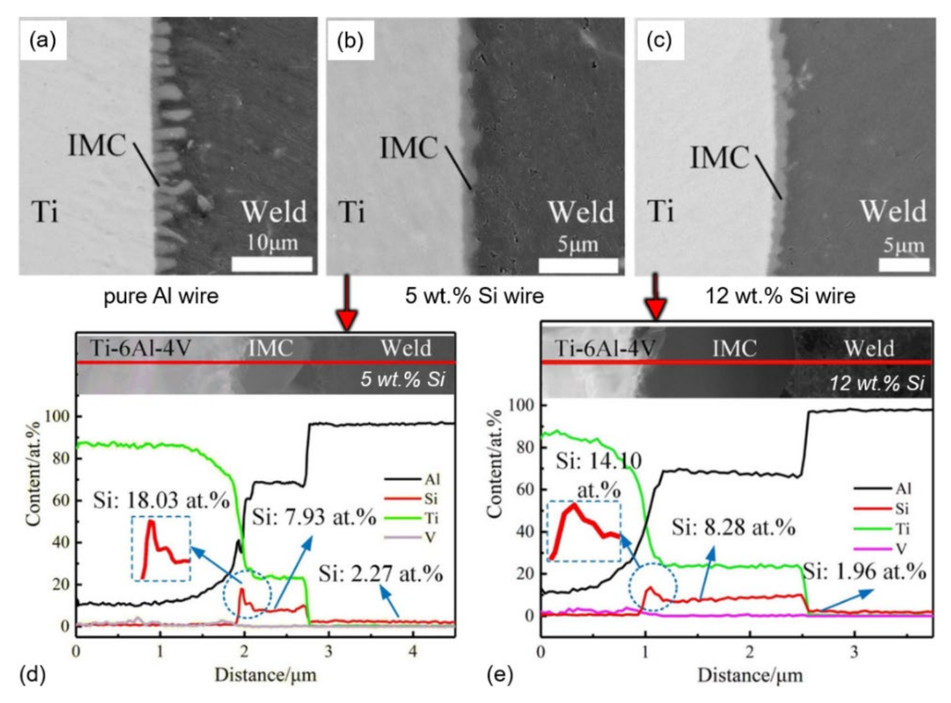
The IMC layer thickness can be effectively suppressed by filler wire with 5 wt.% Si by changing the chemical composition. As an alternative, interlayer coatings are effective. Further development of filler wires is required. So far, the most widely studied are Si-alloyed and Zn-based filler wires. More advanced filler wires may provide an enhanced microstructure, improved spreading distances and bonding strength.
An important factor is the type of joint and stress/strain distribution at the IMC layer interface. Thus, the bevelling angle is an important factor to consider. The effect of residual stresses and stress/strain fields on mechanical properties is not widely studied. However, dissimilar materials exert much of the strain field, due to the high difference in the thermophysical properties and contraction upon cooling. The optimisation of process parameters is more complex in satisfying the adapted stress field, thermal cycle affecting microstructure and welding defects (cracking and pores).
There is a necessity to use newer techniques, e.g., preheating with pulsed laser, laser ablation of oxide Al alloy prior welding, external factors (ultrasound/mechanical vibrations), as they may further improve the weldability and strength of joints. The use of fluxes was proven to increase the quality of the joints by removing oxides from surfaces effectively. However, there is very low development towards more effective and less aggressive types of fluxes. A multi-beam system may provide a solution to the challenges. However, they are more complex than single beam solutions. Laser beam oscillations may help to improve spearing distances along higher tolerances to air gaps. Moreover, the morphology of IMC layer can be manipulated. However, the penetration depth may be reduced, and heat inputs may be increased. The application of acoustic vibrations during welding may provide a more uniform IMC layer morphology, grain refinement, lower porosity (as described in [185,186,187]) and is very rarely published. Surface texturing and surface roughness optimisation can significantly improve strength by increasing the bonding area. It is scarcely studied, and there is a large room for newer discoveries. However, surface modification may add substantial additional costs for production and should be carefully accessed.
Numerical simulation of the IMC later formation and growth in multi-materials system is scarcely studied, due to its complexity. In welding, more complex physical phenomena are involved; the IMC layer growth may deviate from parabolic law and its thickness prediction with mechanical properties is challenging. This is mainly related to high thermal gradients and stronger heat convection by fast melt flows.
Hydrogen trapping and precipitation, due to its high solubility in Al alloys within a multi-material system, has been scarcely addressed. Hydrogen may significantly degrade the mechanical properties of joints. Thus, more studies are expected in this area.
In the case of Cu–Al joining, electrical conductivity plays a vital role, and thus, parameters and IMC layer characteristics should provide low electrical resistance. In general, Cu–Al joining may be more challenging since Cu is a highly conductive and reflective material. Therefore, more advanced laser systems are required with shorter wavelengths (<500 nm). However, these lasers have power limitation (<2 kW) with low beam quality that is unable to be focused to smaller spots for advanced manufacturing, having wider windows for heat inputs. There is a trend to substitute Cu with mode advanced Al alloys, due to weight and costs. However, the electrical conductivity of Al alloys must be enhanced for energy sector needs. Moreover, the weldability of these alloys should also be considered. In addition, due to Cu, more advanced techniques for phase recognition are required.
As a result, high mechanical properties and integrity of welded joints can be achieved by the optimisation of many process parameters and factors with implementation of the innovative techniques, which represent a significant challenge.
The future research direction for the filling knowledge gaps may include better understanding of formation and growth of the IMCs during welding and their properties after welding, more advanced filler materials and cost-effective interlayers allowing higher heat inputs to use for enhanced productivity, and advanced filler materials for improved corrosion resistance in harsh environments. In laser-based welding–brazing, more in-depth research of the process parameters and heat source interaction would be beneficial for a more stable process, providing improved quality welds.

9. Concluding Remarks

Based on the studied material systems (Fe–Al, Cu–Al, and Ti–Al), the identified main factors contributing to the strength are as follows:
  • Thickness of the IMC layer. Optimisation of welding parameters, mainly by controlling the heat input, provides appropriate thickness of the IMC layer. The optimal thickness reported to be 10 µm for the Fe–Al case. For the Ti–Al case, the optimal IMC layer thickness is 2–3 µm and for the Cu–Al case, it is 5–7 µm.
  • Morphology or continuity of the IMC layer. A uniform IMC layer provides higher strength by ductile fracture, compared to discontinuous and/or serrated-like morphology that has higher stress concentration.
  • Optimisation of the thermal cycle can lead to more ductile phase generation in the IMC layer, and hence, higher strength and ductility.
  • Laser beam welding systems are more flexible and may provide enhanced productivity and quality than conventional arc welding methods.
  • The use of (i) dual-spot laser welding technique, (ii) rectangular spot, and (iii) mechanical vibrations and oscillations may provide more uniform IMC layer morphology and reduce its thickness.
  • Larger wetting or spreading distance of filler wire may significantly increase the joint strength.
  • Application of appropriate filler material, e.g., Si-rich wire, affects the IMC composition and may prevent its growth. Zn-based filler wire can improve the corrosion resistance and weld strength.
  • The preplaced interlayer (Fe, Cu, Ti, Co, Ni) may change the composition of the IMC layer and suppress its growth, similar to filler wire.
  • The use of flux removes harmful oxides and mitigates oxidation. Therefore, it may improve the weld strength significantly by improving the wetting angle, distances, and metallurgical bonding.

Author Contributions

Conceptualisation, I.B., O.M.A. and S.G.-D.; software, I.B.; validation, I.B.; formal analysis, I.B. and O.M.A.; investigation, I.B.; data curation, I.B.; writing—original draft preparation, I.B.; writing—review and editing, O.M.A., X.R. and S.G.-D.; visualisation, I.B.; supervision, O.M.A., X.R., B.N., M.E. and S.G.-D.; project administration, X.R. and S.G.-D.; funding acquisition, X.R. and S.G.-D. All authors have read and agreed to the published version of the manuscript.

Funding

Funded by Research Council of Norway through SFI Manufacturing under contract No. 237900.

Institutional Review Board Statement

Not applicable.

Informed Consent Statement

Not applicable.

Data Availability Statement

Data are contained within the article.

Acknowledgments

The authors wish to thank the Research Council of Norway.

Conflicts of Interest

The authors declare no conflict of interest.

References

  1. Safeen, M.W.; Russo Spena, P. Main issues in quality of friction stir welding joints of aluminum alloy and steel sheets. Metals 2019, 9, 610. [Google Scholar] [CrossRef] [Green Version]
  2. Lee, S.S.; Kim, T.H.; Hu, S.J.; Cai, W. Joining technologies for automotive lithium-ion battery manufacturing—A review. In Proceedings of the ASME 2010 International Manufacturing Science and Engineering Conference (MSEC2010), Erie, PA, USA, 12–15 October 2010. [Google Scholar]
  3. Scrosati, B.; Garche, J. Lithium batteries: Status, prospects and future. J. Power Sources 2010, 195, 2419–2430. [Google Scholar] [CrossRef]
  4. Das, A.; Li, D.; Williams, D.; Greenwood, D. Joining technologies for automotive battery systems manufacturing. World Electr. Veh. J. 2018, 9, 22. [Google Scholar] [CrossRef] [Green Version]
  5. Kobayashi, S.; Yakou, T. Control of intermetallic compound layers at interface between steel and aluminum by diffusion-treatment. Mater. Sci. Eng. A 2002, 338, 44–53. [Google Scholar] [CrossRef]
  6. Dharmendra, C.; Rao, K.P.; Wilden, J.; Reich, S. Study on laser welding-brazing of zinc coated steel to aluminum alloy with a zinc based filler. Mater. Sci. Eng. A 2011, 528, 1497–1503. [Google Scholar] [CrossRef]
  7. Yu, X.; Fan, D.; Huang, J.; Li, C.; Kang, Y. Arc-assisted laser welding brazing of aluminum to steel. Metals 2019, 9, 397. [Google Scholar] [CrossRef] [Green Version]
  8. Du, Y.; Chang, Y.A.; Huang, B.; Gong, W.; Jin, Z.; Xu, H.; Yuan, Z.; Liu, Y.; He, Y.; Xie, F.Y. Diffusion coefficients of some solutes in fcc and liquid Al: Critical evaluation and correlation. Mater. Sci. Eng. A 2003, 363, 140–151. [Google Scholar] [CrossRef]
  9. Springer, H.; Kostka, A.; Payton, E.J.; Raabe, D.; Kaysser-Pyzalla, A.; Eggeler, G. On the formation and growth of intermetallic phases during interdiffusion between low-carbon steel and aluminum alloys. Acta Mater. 2011, 59, 1586–1600. [Google Scholar] [CrossRef]
  10. Shannon, G. Improve Tab to Terminal Connections in Battery Pack Manufacturing; Amada Miyachi America, Inc.: Monrovia, CA, USA, 2016. [Google Scholar]
  11. Backhaus, R. It’s all in the Mix. ATZ Worldw. 2017, 119, 8–13. [Google Scholar] [CrossRef]
  12. Fan, J.; Thomy, C.; Vollertsen, F. Effect of thermal cycle on the formation of intermetallic compounds in laser welding of aluminum-steel overlap joints. Phys. Procedia 2011, 12, 134–141. [Google Scholar] [CrossRef] [Green Version]
  13. Yin, F.-C.; Zhao, M.-X.; Liu, Y.-X.; Han, W.; Li, Z. Effect of Si on growth kinetics of intermetallic compounds during reaction between solid iron and molten aluminum. Trans. Nonferrous Metals Soc. China 2013, 23, 556–561. [Google Scholar] [CrossRef]
  14. Zhao, Y.; Li, J.; Qiu, R.; Shi, H. Growth characterization of intermetallic compound at the Ti/Al solid state interface. Materials 2019, 12, 472. [Google Scholar] [CrossRef] [PubMed] [Green Version]
  15. Moisy, F.; Sauvage, X.; Hug, E. Investigation of the early stage of reactive interdiffusion in the Cu-Al system by in-situ transmission electron microscopy. Materialia 2020, 9, 100633. [Google Scholar] [CrossRef]
  16. Ma, H.; Ren, K.; Xiao, X.; Qiu, R.; Shi, H. Growth characterization of intermetallic compounds at the Cu/Al solid state interface. Mater. Res. Express 2019, 6, 106544. [Google Scholar] [CrossRef]
  17. Feng, J.; Xue, S. Growth behaviors of intermetallic compound layers in Cu/Al joints brazed with Zn–22Al and Zn–22Al–0.05Ce filler metals. Mater. Des. 2013, 51, 907–915. [Google Scholar] [CrossRef]
  18. Zhou, Y.; Lin, Q. Wetting of galvanized steel by Al 4043 alloys in the first cycle of CMT process. J. Alloy. Compd. 2014, 589, 307–313. [Google Scholar] [CrossRef]
  19. Akselsen, O.M. Advances in brazing of ceramics. J. Mater. Sci. 1992, 27, 1989–2000. [Google Scholar] [CrossRef]
  20. Ion, J.C. Laser beam welding of wrought aluminium alloys. Sci. Technol. Weld. Join. 2000, 5, 265–276. [Google Scholar] [CrossRef]
  21. Cho, W.-I.; Schultz, V.; Woizeschke, P. Numerical study of the effect of the oscillation frequency in buttonhole welding. J. Mater. Process. Technol. 2018, 261, 202–212. [Google Scholar] [CrossRef]
  22. Schultz, V.; Woizeschke, P. High seam surface quality in keyhole laser welding: Buttonhole welding. J. Manuf. Mater. Process. 2018, 2, 78. [Google Scholar] [CrossRef] [Green Version]
  23. Zacharia, T.; David, S.A.; Vitek, J.M.; DebRoy, T. Modeling of interfacial phenomena in welding. Metall. Trans. B 1990, 21, 600–603. [Google Scholar] [CrossRef]
  24. Behler, K.; Berkmanns, J.; Ehrhardt, A.; Frohn, W. Laser beam welding of low weight materials and structures. Mater. Des. 1997, 18, 261–267. [Google Scholar] [CrossRef]
  25. Otto, A.; Vázquez, R.G.; Hartel, U.; Mosbah, S. Numerical analysis of process dynamics in laser welding of Al and Cu. Procedia CIRP 2018, 74, 691–695. [Google Scholar] [CrossRef]
  26. Bunaziv, I.; Akselsen, O.M.; Ren, X.; Nyhus, B.; Eriksson, M. Laser beam and laser-arc hybrid welding of aluminium alloys. Metals 2021, 11, 1150. [Google Scholar] [CrossRef]
  27. Mys, I.; Schmidt, M. Laser Micro Welding of Copper and Aluminu. In Proceedings of the Lasers and Applications in Science and Engineering, San Jose, CA, USA, 21–26 January 2006; Volume 6107. [Google Scholar]
  28. ISO. 13919-1—Welding—Electron and Laser-Beam Welded Joints—Guidance on Quality Levels for Imperfections—Part 1: Steel; International Organization for Standardization: Geneva, Switzerland, 1996; p. 7. [Google Scholar]
  29. ISO. 13919-2—Welding—Electron and Laser-Beam Welded Joints—Guidance on Quality Levels for Imperfections—Part 2: Aluminium and Its Weldable Alloys; International Organization for Standardization: Geneva, Switzerland, 2001. [Google Scholar]
  30. Wei, P.-S. Thermal science of weld bead defects: A review. J. Heat Transf. 2010, 133, 031005. [Google Scholar] [CrossRef]
  31. Zhao, H.; Debroy, T. Weld metal composition change during conduction mode laser welding of aluminum alloy 5182. Metall. Mater. Trans. B 2001, 32, 163–172. [Google Scholar] [CrossRef]
  32. Arora, A.; Roy, G.G.; DebRoy, T. Unusual wavy weld pool boundary from dimensional analysis. Scr. Mater. 2009, 60, 68–71. [Google Scholar] [CrossRef]
  33. Eriksson, I.; Powell, J.; Kaplan, A.F.H. Surface tension generated defects in full penetration laser keyhole welding. J. Laser Appl. 2014, 26, 012006. [Google Scholar] [CrossRef]
  34. Zhang, R.; Tang, X.; Xu, L.; Lu, F.; Cui, H. Study of molten pool dynamics and porosity formation mechanism in full penetration fiber laser welding of Al-alloy. Int. J. Heat Mass Transf. 2020, 148, 119089. [Google Scholar] [CrossRef]
  35. Schmidt, L.; Schricker, K.; Bergmann, J.P.; Junger, C. Effect of local gas flow in full penetration laser beam welding with high welding speeds. Appl. Sci. 2020, 10, 1867. [Google Scholar] [CrossRef] [Green Version]
  36. Kawahito, Y.; Uemura, Y.; Doi, Y.; Mizutani, M.; Nishimoto, K.; Kawakami, H.; Tanaka, M.; Fujii, H.; Nakata, K.; Katayama, S. Elucidation of the effect of welding speed on melt flows in high-brightness and high-power laser welding of stainless steel on basis of three-dimensional X-ray transmission in situ observation. Weld. Int. 2017, 31, 206–213. [Google Scholar] [CrossRef]
  37. Frostevarg, J.; Kaplan, A. Undercut suppression in laser-arc hybrid welding by melt pool tailoring. J. Laser Appl. 2014, 26. [Google Scholar] [CrossRef]
  38. Karlsson, J.; Norman, P.; Kaplan, A.F.H.; Rubin, P.; Lamas, J.; Yañez, A. Observation of the mechanisms causing two kinds of undercut during laser hybrid arc welding. Appl. Surf. Sci. 2011, 257, 7501–7506. [Google Scholar] [CrossRef]
  39. Wang, J.-B.; Nishimura, H.; Katayama, S.; Mizutani, M. Welding of aluminium alloy by using filler-added laser-arc hybrid welding process. Weld. Int. 2013, 27, 98–108. [Google Scholar] [CrossRef]
  40. Enz, J.; Riekehr, S.; Ventzke, V.; Huber, N.; Kashaev, N. Fibre laser welding of high-alloyed Al–Zn–Mg–Cu alloys. J. Mater. Process. Technol. 2016, 237, 155–162. [Google Scholar] [CrossRef]
  41. Xia, H.; Zhang, L.; Tan, C.; Wu, L.; Chen, B.; Li, L. Effect of heat input on a laser powder deposited Al/steel butt joint. Opt. Laser Technol. 2019, 111, 459–469. [Google Scholar] [CrossRef]
  42. Sun, J.; Yan, Q.; Gao, W.; Huang, J. Investigation of laser welding on butt joints of Al/steel dissimilar materials. Mater. Des. 2015, 83, 120–128. [Google Scholar] [CrossRef]
  43. Chen, S.; Li, S.; Li, Y.; Huang, J.; Chen, S.; Yang, J. Butt welding-brazing of steel to aluminum by hybrid laser-CMT. J. Mater. Process. Technol. 2019, 272, 163–169. [Google Scholar] [CrossRef]
  44. Cao, X.; Zhou, X.; Wang, H.; Luo, Z.; Duan, J.A. Microstructures and mechanical properties of laser offset welded 5052 aluminum to press-hardened steel. J. Mater. Res. Technol. 2020, 9, 5378–5390. [Google Scholar] [CrossRef]
  45. Qin, G.; Lei, Z.; Su, Y.; Fu, B.; Meng, X.; Lin, S. Large spot laser assisted GMA brazing—fusion welding of aluminum alloy to galvanized steel. J. Mater. Process. Technol. 2014, 214, 2684–2692. [Google Scholar] [CrossRef]
  46. Sun, J.; Yan, Q.; Li, Z.; Huang, J. Effect of bevel angle on microstructure and mechanical property of Al/steel butt joint using laser welding-brazing method. Mater. Des. 2016, 90, 468–477. [Google Scholar] [CrossRef]
  47. Li, L.; Xia, H.; Tan, C.; Ma, N. Influence of laser power on interfacial microstructure and mechanical properties of laser welded-brazed Al/steel dissimilar butted joint. J. Manuf. Process. 2018, 32, 160–174. [Google Scholar] [CrossRef]
  48. Gao, M.; Chen, C.; Gu, Y.; Zeng, X. Microstructure and tensile behavior of laser arc hybrid welded dissimilar Al and Ti alloys. Materials 2014, 7, 1590–1602. [Google Scholar] [CrossRef] [PubMed]
  49. Tomashchuk, I.; Sallamand, P.; Méasson, A.; Cicala, E.; Duband, M.; Peyre, P. Aluminum to titanium laser welding-brazing in V-shaped groove. J. Mater. Process. Technol. 2017, 245, 24–36. [Google Scholar] [CrossRef]
  50. Li, P.; Lei, Z.; Zhang, X.; Chen, Y. Influence of Si content on interfacial reactions and mechanical properties of dual-spot laser welded-brazed Ti/Al joints. J. Manuf. Proces. 2020, 56, 950–966. [Google Scholar] [CrossRef]
  51. Li, P.; Lei, Z.; Zhang, X.; Cai, E.; Chen, Y. The microstructure and mechanical properties of dual-spot laser welded-brazed Ti/Al butt joints with different groove Shapes. Materials 2020, 13, 5105. [Google Scholar] [CrossRef] [PubMed]
  52. Lei, Z.; Li, P.; Zhang, X.; Wu, S.; Zhou, H.; Nannan, L. Microstructure and mechanical properties of welding—brazing of Ti/Al butt joints with laser melting deposition layer additive. J. Manuf. Process. 2019, 38, 411–421. [Google Scholar] [CrossRef]
  53. Li, P.; Lei, Z.; Zhang, X.; Liu, J.; Chen, Y. Effects of laser power on the interfacial intermetallic compounds and mechanical properties of dual-spot laser welded—brazed Ti/Al butt joint. Opt. Laser Technol. 2020, 124, 105987. [Google Scholar] [CrossRef]
  54. Mathers, G. The Welding of Aluminium and Its Alloys; Woodhead Publishing: Cambridge, UK, 2002; p. 248. [Google Scholar]
  55. Ahn, J.; He, E.; Chen, L.; Wimpory, R.C.; Kabra, S.; Dear, J.P.; Davies, C.M. FEM prediction of welding residual stresses in fibre laser-welded AA 2024-T3 and comparison with experimental measurement. Int. J. Adv. Manuf. Technol. 2018, 95, 4243–4263. [Google Scholar] [CrossRef]
  56. Westbrook, J.H.; Fleischer, R.L. (Eds.) Intermetallic Compounds: Principles and Practice, Vol. 1: Principles; John Wiley and Sons Ltd.: Hoboken, NJ, USA, 1995; Volume 1. [Google Scholar]
  57. Weast, R.C. Handbook of Chemistry and Physics, 54th ed.; CRC Press: Boca Raton, FL, USA, 1973. [Google Scholar]
  58. ASM International. ASM Handbook: Properties and Selection: Nonferrous Alloys and Special-Purpose Materials; ASM International: Almere, The Netherlands, 1990; Volume 2, p. 1328. [Google Scholar]
  59. Mondolfo, L.F. Aluminum Alloys: Structure and Properties; Butterworth-Heinemann: Oxford, UK, 1976; p. 982. [Google Scholar] [CrossRef]
  60. Powell, R.W.; Ho, C.Y.; Liley, P.E. Thermal Conductivity of Selected Materials; National Bureau of Standard: Washington, DC, USA, 1966.
  61. Katayama, S. Handbook of Laser Welding Technologies; Woodhead Publishing: Cambridge, UK, 2013. [Google Scholar]
  62. Hummel, M.; Schöler, C.; Häusler, A.; Gillner, A.; Poprawe, R. New approaches on laser micro welding of copper by using a laser beam source with a wavelength of 450 nm. J. Adv. Join. Process. 2020, 1, 100012. [Google Scholar] [CrossRef]
  63. Britten, S.W.; Schmid, L.; Molitor, T.; Rütering, M. Blue high-power laser sources for processing solutions in e-mobility and beyond. Procedia CIRP 2020, 94, 592–595. [Google Scholar] [CrossRef]
  64. Baumann, M.; Balck, A.; Malchus, J.; Chacko, R.; Marfels, S.; Witte, U.; Dinakaran, D.; Ocylok, S.; Weinbach, M.; Bachert, C.; et al. 1000 W Blue Fiber-Coupled Diode-Laser Emitting at 450 NM. In Proceedings of the The International Society for Optics and Photonics, San Diego, CA, USA, 11–15 August 2019; Volume 10900. [Google Scholar]
  65. Pierron, N.; Sallamand, P.; Matteï, S. Study of magnesium and aluminum alloys absorption coefficient during Nd:YAG laser interaction. Appl. Surf. Sci. 2007, 253, 3208–3214. [Google Scholar] [CrossRef]
  66. Kawahito, Y.; Matsumoto, N.; Abe, Y.; Katayama, S. Laser absorption of aluminium alloy in high brightness and high power fibre laser welding. Weld. Int. 2012, 26, 275–281. [Google Scholar] [CrossRef]
  67. Miyagi, M.; Wang, H.; Yoshida, R.; Kawahito, Y.; Kawakami, H.; Shoubu, T. Effect of alloy element on weld pool dynamics in laser welding of aluminum alloys. Sci. Rep. 2018, 8, 12944. [Google Scholar] [CrossRef]
  68. Ning, J.; Zhang, L.-J.; Yin, X.-Q.; Zhang, J.-X.; Na, S.-J. Mechanism study on the effects of power modulation on energy coupling efficiency in infrared laser welding of highly-reflective materials. Mater. Des. 2019, 178, 107871. [Google Scholar] [CrossRef]
  69. Malekshahi Beiranvand, Z.; Malek Ghaini, F.; Naffakh Moosavy, H.; Sheikhi, M.; Torkamany, M.J.; Moradi, M. The relation between magnesium evaporation and laser absorption and weld penetration in pulsed laser welding of aluminum alloys: Experimental and numerical investigations. Opt. Laser Technol. 2020, 128, 106170. [Google Scholar] [CrossRef]
  70. Lisiecki, A. Study of optical properties of surface layers produced by laser surface melting and laser surface nitriding of titanium alloy. Metals 2019, 12, 3112. [Google Scholar] [CrossRef] [Green Version]
  71. Bunaziv, I.; Akselsen, O.M.; Frostevarg, J.; Kaplan, A.F.H. Deep penetration fiber laser-arc hybrid welding of thick HSLA steel. J. Mater. Process. Technol. 2018, 256, 216–228. [Google Scholar] [CrossRef]
  72. Thomy, C.; Vollertsen, F. Laser-mig hybrid welding of aluminium to steel—Effect of process parameters on joint properties. Weld. World 2012, 56, 124–132. [Google Scholar] [CrossRef]
  73. Jia, L.; Shichun, J.; Yan, S.; Cong, N.; Junke, C.; Genzhe, H. Effects of zinc on the laser welding of an aluminum alloy and galvanized steel. J. Mater. Process. Technol. 2015, 224, 49–59. [Google Scholar] [CrossRef]
  74. Zhang, Y.; Li, F.; Guo, G.; Wang, G.; Wei, H. Effects of different powders on the micro-gap laser welding-brazing of an aluminium-steel butt joint using a coaxial feeding method. Mater. Des. 2016, 109, 10–18. [Google Scholar] [CrossRef]
  75. Chen, Y.; Yang, Z.; Shi, C.; Xin, Z.; Zeng, Z. Laser-CMT hybrid welding-brazing of Al/steel butt joint: Weld formation, intermetallic compounds, and mechanical properties. Materials 2019, 12, 3651. [Google Scholar] [CrossRef] [Green Version]
  76. Xia, H.; Tao, W.; Li, L.; Tan, C.; Zhang, K.; Ma, N. Effect of laser beam models on laser welding—brazing Al to steel. Opt. Laser Technol. 2020, 122, 105845. [Google Scholar] [CrossRef]
  77. Zhu, Z.; Wang, W.; Li, Y.; Chen, H. Effect of laser-arc offset and laser-deviation angle on the control of a Ti-Al interlayer. J. Mater. Process. Technol. 2019, 271, 336–345. [Google Scholar] [CrossRef]
  78. Guo, S.; Peng, Y.; Cui, C.; Gao, Q.; Zhou, Q.; Zhu, J. Microstructure and mechanical characterization of re-melted Ti-6Al-4V and Al-Mg-Si alloys butt weld. Vacuum 2018, 154, 58–67. [Google Scholar] [CrossRef]
  79. Cui, L.; Wei, Z.; Ma, B.; He, D.; Huang, H.; Cao, Q. Microstructure inhomogeneity of dissimilar steel/Al butt joints produced by laser offset welding. J. Manuf. Process. 2020, 50, 561–572. [Google Scholar] [CrossRef]
  80. Cui, L.; Chen, B.; Qian, W.; He, D.; Chen, L. Microstructures and mechanical properties of dissimilar Al/steel butt joints produced by autogenous laser keyhole welding. Metals 2017, 7, 492. [Google Scholar] [CrossRef] [Green Version]
  81. Tan, C.; Zang, C.; Xia, H.; Zhao, X.; Zhang, K.; Meng, S.; Chen, B.; Song, X.; Li, L. Influence of Al additions in Zn—based filler metals on laser welding—brazing of Al/steel. J. Manuf. Process. 2018, 34, 251–263. [Google Scholar] [CrossRef]
  82. Laukant, H.; Wallmann, C.; Müller, M.; Korte, M.; Stirn, B.; Haldenwanger, H.G.; Glatzel, U. Fluxless laser beam joining of aluminium with zinc coated steel. Sci. Technol. Weld. Join. 2005, 10, 219–226. [Google Scholar] [CrossRef]
  83. Agudo, L.; Eyidi, D.; Schmaranzer, C.H.; Arenholz, E.; Jank, N.; Bruckner, J.; Pyzalla, A.R. Intermetallic FexAly-phases in a steel/Al-alloy fusion weld. J. Mater. Sci. 2007, 42, 4205–4214. [Google Scholar] [CrossRef]
  84. Singh, J.; Arora, K.S.; Shukla, D.K. Dissimilar MIG-CMT weld-brazing of aluminium to steel: A review. J. Alloy. Compd. 2019, 783, 753–764. [Google Scholar] [CrossRef]
  85. Yuan, R.; Deng, S.; Cui, H.; Chen, Y.; Lu, F. Interface characterization and mechanical properties of dual beam laser welding-brazing Al/steel dissimilar metals. J. Manuf. Process. 2019, 40, 37–45. [Google Scholar] [CrossRef]
  86. Yagati, K.P.; Bathe, R.N.; Rajulapati, K.V.; Sankara Rao, K.B.; Padmanabham, G. Fluxless arc weld-brazing of aluminium alloy to steel. J. Mater. Process. Technol. 2014, 214, 2949–2959. [Google Scholar] [CrossRef]
  87. Jimenez-Mena, N.; Simar, A.; Jacques, P.J. On the interplay between intermetallic controlled growth and hot tearing susceptibility in Al-to-steel welding with additional interlayers. Mater. Des. 2019, 180, 107958. [Google Scholar] [CrossRef]
  88. ASM International. ASM Handbook: Alloy Phase Diagrams; ASM International: Materials Park, OH, USA, 2007; Volume 3. [Google Scholar]
  89. Sundman, B.; Ohnuma, I.; Dupin, N.; Kattner, U.R.; Fries, S.G. An assessment of the entire Al–Fe system including D03 ordering. Acta Mater. 2009, 57, 2896–2908. [Google Scholar] [CrossRef]
  90. Zhu, L.; Soto-Medina, S.; Cuadrado-Castillo, W.; Hennig, R.G.; Manuel, M.V. New experimental studies on the phase diagram of the Al-Cu-Fe quasicrystal-forming system. Mater. Des. 2020, 185, 108186. [Google Scholar] [CrossRef]
  91. Gullino, A.; Matteis, P.; D’Aiuto, F. Review of aluminum-to-steel welding technologies for car-body applications. Metals 2019, 9, 315. [Google Scholar] [CrossRef] [Green Version]
  92. Sierra, G.; Peyre, P.; Deschaux-Beaume, F.; Stuart, D.; Fras, G. Steel to aluminium key-hole laser welding. Mater. Sci. Eng. A 2007, 447, 197–208. [Google Scholar] [CrossRef]
  93. Springer, H.; Szczepaniak, A.; Raabe, D. On the role of zinc on the formation and growth of intermetallic phases during interdiffusion between steel and aluminium alloys. Acta Mater. 2015, 96, 203–211. [Google Scholar] [CrossRef]
  94. Torkamany, M.J.; Tahamtan, S.; Sabbaghzadeh, J. Dissimilar welding of carbon steel to 5754 aluminum alloy by Nd:YAG pulsed laser. Mater. Des. 2010, 31, 458–465. [Google Scholar] [CrossRef]
  95. Szczepaniak, A. Investigation of Intermetallic Layer Formation in Dependence of Process Parameters during the Thermal Joining of Aluminium With Steel; RWTH: Aachen, Germany, 2016. [Google Scholar]
  96. Ciołek, S.; Jóźwiak, S.; Karczewski, K. Possibility of strengthening aluminum using low-symmetry phases of the Fe-Al binary system. Metall. Mater. Trans. A 2019, 50, 1914–1921. [Google Scholar] [CrossRef] [Green Version]
  97. Yeremenko, V.N.; Natanzon, Y.V.; Dybkov, V.I. The effect of dissolution on the growth of the Fe2Al5 interlayer in the solid iron-liquid aluminium system. J. Mater. Sci. 1981, 16, 1748–1756. [Google Scholar] [CrossRef]
  98. Li, Y.; Liu, Y.; Yang, J. First principle calculations and mechanical properties of the intermetallic compounds in a laser welded steel/aluminum joint. Opt. Laser Technol. 2020, 122, 105875. [Google Scholar] [CrossRef]
  99. Xia, H.; Zhao, X.; Tan, C.; Chen, B.; Song, X.; Li, L. Effect of Si content on the interfacial reactions in laser welded-brazed Al/steel dissimilar butted joint. J. Mater. Process. Technol. 2018, 258, 9–21. [Google Scholar] [CrossRef]
  100. Meco, S.; Pardal, G.; Ganguly, S.; Williams, S.; McPherson, N. Application of laser in seam welding of dissimilar steel to aluminium joints for thick structural components. Opt. Lasers Eng. 2015, 67, 22–30. [Google Scholar] [CrossRef] [Green Version]
  101. Chen, S.; Yang, D.; Zhang, M.; Huang, J.; Zhao, X. Interaction between the growth and dissolution of intermetallic compounds in the interfacial reaction between solid iron and liquid aluminum. Metall. Mater. Trans. A 2016, 47, 5088–5100. [Google Scholar] [CrossRef]
  102. Xu, G.; Wang, K.; Dong, X.; Yang, L.; Ebrahimi, M.; Jiang, H.; Wang, Q.; Ding, W. Review on corrosion resistance of mild steels in liquid aluminum. J. Mater. Sci. Technol. 2021, 71, 12–22. [Google Scholar] [CrossRef]
  103. Song, J.L.; Lin, S.B.; Yang, C.L.; Fan, C.L. Effects of Si additions on intermetallic compound layer of aluminum-steel TIG welding—brazing joint. J. Alloy. Compd. 2009, 488, 217–222. [Google Scholar] [CrossRef]
  104. Tanaka, T.; Morishige, T.; Hirata, T. Comprehensive analysis of joint strength for dissimilar friction stir welds of mild steel to aluminum alloys. Scr. Mater. 2009, 61, 756–759. [Google Scholar] [CrossRef]
  105. Matsuda, T.; Hatano, R.; Ogura, T.; Suzuki, R.; Shoji, H.; Sano, T.; Ohata, M.; Hirose, A. Effect of mismatch in mechanical properties on interfacial strength of aluminum alloy/steel dissimilar joints. Mater. Sci. Eng. A 2020, 786, 139437. [Google Scholar] [CrossRef]
  106. Sierra, G.; Peyre, P.; Deschaux Beaume, F.; Stuart, D.; Fras, G. Galvanised steel to aluminium joining by laser and GTAW processes. Mater. Charact. 2008, 59, 1705–1715. [Google Scholar] [CrossRef]
  107. Mathieu, A.; Shabadi, R.; Deschamps, A.; Suery, M.; Matteï, S.; Grevey, D.; Cicala, E. Dissimilar material joining using laser (aluminum to steel using zinc-based filler wire). Opt. Laser Technol. 2007, 39, 652–661. [Google Scholar] [CrossRef]
  108. Pardal, G.; Meco, S.; Dunn, A.; Williams, S.; Ganguly, S.; Hand, D.P.; Wlodarczyk, K.L. Laser spot welding of laser textured steel to aluminium. J. Mater. Process. Technol. 2017, 241, 24–35. [Google Scholar] [CrossRef] [Green Version]
  109. Li, L.; Xia, H.; Tan, C.; Ma, N. Effect of groove shape on laser welding-brazing Al to steel. J. Mater. Process. Technol. 2018, 252, 573–581. [Google Scholar] [CrossRef]
  110. Trinh, L.N.; Lee, D. The characteristics of laser welding of a thin aluminum tab and steel battery case for lithium-ion battery. Metals 2020, 10, 842. [Google Scholar] [CrossRef]
  111. Nickel Institute. Nickel Plating Handbook; Nickel Institute: Toronto, ON, Canada, 2014. [Google Scholar]
  112. Brunelli, K.; Peruzzo, L.; Dabalà, M. The effect of prolonged heat treatments on the microstructural evolution of Al/Ni intermetallic compounds in multi layered composites. Mater. Chem. Phys. 2015, 149, 350–358. [Google Scholar] [CrossRef]
  113. Mozaffari, A.; Hosseini, M.; Manesh, H.D. Al/Ni metal intermetallic composite produced by accumulative roll bonding and reaction annealing. J. Alloy. Compd. 2011, 509, 9938–9945. [Google Scholar] [CrossRef]
  114. Arbo, S.M.; Bergh, T.; Holmedal, B.; Vullum, P.E.; Westermann, I. Relationship between Al-Ni intermetallic phases and bond strength in roll bonded steel-aluminum composites with nickel interlayers. Metals 2019, 9, 827. [Google Scholar] [CrossRef] [Green Version]
  115. Eleno, L.; Frisk, K.; Schneider, A. Assessment of the Fe–Ni–Al system. Intermetallics 2006, 14, 1276–1290. [Google Scholar] [CrossRef]
  116. Chen, S.; Huang, J.; Ma, K.; Zhang, H.; Zhao, X. Influence of a Ni-foil interlayer on Fe/Al dissimilar joint by laser penetration welding. Mater. Lett. 2012, 79, 296–299. [Google Scholar] [CrossRef]
  117. Reddy, M.G.; Rao, S.A.; Mohandas, T. Role of electroplated interlayer in continuous drive friction welding of AA6061 to AISI 304 dissimilar metals. Sci. Technol. Weld. Join. 2008, 13, 619–628. [Google Scholar] [CrossRef]
  118. Kannan, P.S.; Balamurugan, K.; Thirunavukkarasu, K. Influence of silver interlayer in dissimilar 6061-T6 aluminum MMC and AISI 304 stainless steel friction welds. Int. J. Adv. Manuf. Technol. 2015, 81, 1743–1756. [Google Scholar] [CrossRef]
  119. Jimenez-Mena, N.; Jacques, P.J.; Ding, L.; Gauquelin, N.; Schryvers, D.; Idrissi, H.; Delannay, F.; Simar, A. Enhancement of toughness of Al-to-steel Friction Melt Bonded welds via metallic interlayers. Mater. Sci. Eng. A 2019, 740, 274–284. [Google Scholar] [CrossRef]
  120. Chen, S.; Zhai, Z.; Huang, J.; Zhao, X.; Xiong, J. Interface microstructure and fracture behavior of single/dual-beam laser welded steel-Al dissimilar joint produced with copper interlayer. Int. J. Adv. Manuf. Technol. 2015, 82, 631–643. [Google Scholar] [CrossRef]
  121. Shi, D.; Wen, B.; Melnik, R.; Yao, S.; Li, T. First-principles studies of Al–Ni intermetallic compounds. J. Solid State Chem. 2009, 182, 2664–2669. [Google Scholar] [CrossRef]
  122. Svanidze, E.; Besara, T.; Ozaydin, M.F.; Tiwary, C.S.; Wang, J.K.; Radhakrishnan, S.; Mani, S.; Xin, Y.; Han, K.; Liang, H.; et al. High hardness in the biocompatible intermetallic compound β-Ti3Au. Sci. Adv. 2016, 2, e1600319. [Google Scholar] [CrossRef] [PubMed] [Green Version]
  123. Shah, L.H.; Gerlich, A.; Zhou, Y. Design guideline for intermetallic compound mitigation in Al-Mg dissimilar welding through addition of interlayer. Int. J. Adv. Manuf. Technol. 2018, 94, 2667–2678. [Google Scholar] [CrossRef]
  124. Weaver, M.L.; Stevenson, M.E.; Bradt, R.C. Knoop microhardness anisotropy and the indentation size effect on the (100) of single crystal NiAl. Mater. Sci. Eng. A 2003, 345, 113–117. [Google Scholar] [CrossRef]
  125. Marder, A.R. The metallurgy of zinc-coated steel. Prog. Mater. Sci. 2000, 45, 191–271. [Google Scholar] [CrossRef]
  126. Dong, H.; Hu, W.; Duan, Y.; Wang, X.; Dong, C. Dissimilar metal joining of aluminum alloy to galvanized steel with Al–Si, Al–Cu, Al–Si–Cu and Zn–Al filler wires. J. Mater. Process. Technol. 2012, 212, 458–464. [Google Scholar] [CrossRef]
  127. Kam, D.H.; Lee, T.H.; Kim, D.Y.; Kim, J.; Kang, M. Weld quality improvement and porosity reduction mechanism of Zinc coated steel using tandem gas metal arc welding (GMAW). J. Mater. Process. Technol. 2021, 294, 117127. [Google Scholar] [CrossRef]
  128. Su, Y.; Hua, X.; Wu, Y. Quantitative characterization of porosity in Fe–Al dissimilar materials lap joint made by gas metal arc welding with different current modes. J. Mater. Process. Technol. 2014, 214, 81–86. [Google Scholar] [CrossRef]
  129. Cao, R.; Yu, G.; Chen, J.H.; Wang, P.-C. Cold metal transfer joining aluminum alloys-to-galvanized mild steel. J. Mater. Process. Technol. 2013, 213, 1753–1763. [Google Scholar] [CrossRef]
  130. Ahsan, M.R.U.; Kim, Y.R.; Kim, C.H.; Kim, J.W.; Ashiri, R.; Park, Y.D. Porosity formation mechanisms in cold metal transfer (CMT) gas metal arc welding (GMAW) of zinc coated steels. Sci. Technol. Weld. Join. 2016, 21, 209–215. [Google Scholar] [CrossRef]
  131. Lin, J.; Ma, N.; Lei, Y.; Murakawa, H. Shear strength of CMT brazed lap joints between aluminum and zinc-coated steel. J. Mater. Process. Technol. 2013, 213, 1303–1310. [Google Scholar] [CrossRef]
  132. Wan, Z.; Wang, H.-P.; Li, J.; Solomon, J.; Zhu, Y.; Carlson, B. Novel measures for spatter prediction in laser welding of thin-gage zinc-coated steel. Int. J. Heat Mass Transf. 2021, 167, 120830. [Google Scholar] [CrossRef]
  133. Hong, K.-M.; Shin, Y.C. Prospects of laser welding technology in the automotive industry: A review. J. Mater. Process. Technol. 2017, 245, 46–69. [Google Scholar] [CrossRef]
  134. Pan, Y.; Richardson, I.M. Keyhole behaviour during laser welding of zinc-coated steel. J. Phys. D Appl. Phys. 2011, 44, 045502. [Google Scholar] [CrossRef]
  135. Pieters, R.R.G.M.; Richardson, I.M. Laser welding of zinc coated steel in overlap configuration with zero gap. Sci. Technol. Weld. Join. 2005, 10, 142–144. [Google Scholar] [CrossRef]
  136. Kim, J.; Oh, S.; Ki, H. Effect of keyhole geometry and dynamics in zero-gap laser welding of zinc-coated steel sheets. J. Mater. Process. Technol. 2016, 232, 131–141. [Google Scholar] [CrossRef]
  137. Gatzen, M.; Radel, T.; Thomy, C.; Vollertsen, F. Wetting behavior of eutectic Al–Si droplets on zinc coated steel substrates. J. Mater. Process. Technol. 2014, 214, 123–131. [Google Scholar] [CrossRef]
  138. Nishimoto, K.; Harano, T.; Okumoto, Y.; Atagi, K.; Fujii, H.; Katayama, S. Mechanical properties of laser-pressure-welded joint between dissimilar galvannealed steel and pure aluminium. Welding Int. 2009, 23, 817–823. [Google Scholar] [CrossRef]
  139. Mita, K.; Ikeda, T.; Maeda, M. Phase diagram study of Fe-Zn intermetallics. J. Phase Equilibria 2001, 22, 122. [Google Scholar] [CrossRef]
  140. Xue, P.; Ni, D.R.; Wang, D.; Xiao, B.L.; Ma, Z.Y. Effect of friction stir welding parameters on the microstructure and mechanical properties of the dissimilar Al–Cu joints. Mater. Sci. Eng. A 2011, 528, 4683–4689. [Google Scholar] [CrossRef]
  141. Tan, C.W.; Jiang, Z.G.; Li, L.Q.; Chen, Y.B.; Chen, X.Y. Microstructural evolution and mechanical properties of dissimilar Al–Cu joints produced by friction stir welding. Mater. Des. 2013, 51, 466–473. [Google Scholar] [CrossRef]
  142. Mehta, K.P.; Badheka, V.J. A review on dissimilar friction stir welding of copper to aluminum: Process, properties, and variants. Mater. Manuf. Process. 2016, 31, 233–254. [Google Scholar] [CrossRef]
  143. Matsuoka, S.-I.; Imai, H. Direct welding of different metals used ultrasonic vibration. J. Mater. Process. Technol. 2009, 209, 954–960. [Google Scholar] [CrossRef]
  144. Liu, J.; Cao, B.; Yang, J. Modelling intermetallic phase growth during high-power ultrasonic welding of copper and aluminum. J. Manuf. Process. 2018, 35, 595–603. [Google Scholar] [CrossRef]
  145. Xiao, Y.; Li, M.; Wang, L.; Huang, S.; Du, X.; Liu, Z. Interfacial reaction behavior and mechanical properties of ultrasonically brazed Cu/Zn–Al/Cu joints. Mater. Des. 2015, 73, 42–49. [Google Scholar] [CrossRef]
  146. Xiao, Y.; Ji, H.; Li, M.; Kim, J. Ultrasound-assisted brazing of Cu/Al dissimilar metals using a Zn–3Al filler metal. Mater. Des. 2013, 52, 740–747. [Google Scholar] [CrossRef]
  147. Xia, C.; Li, Y.; Puchkov, U.A.; Gerasimov, S.A.; Wang, J. Microstructure and phase constitution near the interface of Cu/Al vacuum brazing using Al–Si filler metal. Vacuum 2008, 82, 799–804. [Google Scholar] [CrossRef]
  148. Ponweiser, N.; Lengauer, C.L.; Richter, K.W. Re-investigation of phase equilibria in the system Al–Cu and structural analysis of the high-temperature phase η1-Al1−δCu. Intermetallics 2011, 19, 1737–1746. [Google Scholar] [CrossRef] [Green Version]
  149. Sharma, N.; Khan, Z.A.; Siddiquee, A.N.; Shihab, S.K.; Wahid, M.A. Effect of process parameters on microstructure and electrical conductivity during FSW of Al-6101 and Pure Copper. Mater. Res. Express 2018, 5, 046519. [Google Scholar] [CrossRef]
  150. Lee, W.-B.; Bang, K.-S.; Jung, S.-B. Effects of intermetallic compound on the electrical and mechanical properties of friction welded Cu/Al bimetallic joints during annealing. J. Alloy. Compd. 2005, 390, 212–219. [Google Scholar] [CrossRef]
  151. Zuo, D.; Hu, S.; Shen, J.; Xue, Z. Intermediate layer characterization and fracture behavior of laser-welded copper/aluminum metal joints. Mater. Des. 2014, 58, 357–362. [Google Scholar] [CrossRef]
  152. Xue, P.; Xiao, B.L.; Ni, D.R.; Ma, Z.Y. Enhanced mechanical properties of friction stir welded dissimilar Al–Cu joint by intermetallic compounds. Mater. Sci. Eng. A 2010, 527, 5723–5727. [Google Scholar] [CrossRef]
  153. Yan, S.; Shi, Y. Influence of laser power on microstructure and mechanical property of laser-welded Al/Cu dissimilar lap joints. J. Manuf. Process. 2019, 45, 312–321. [Google Scholar] [CrossRef]
  154. Hang, C.J.; Wang, C.Q.; Mayer, M.; Tian, Y.H.; Zhou, Y.; Wang, H.H. Growth behavior of Cu/Al intermetallic compounds and cracks in copper ball bonds during isothermal aging. Microelectron. Reliab. 2008, 48, 416–424. [Google Scholar] [CrossRef]
  155. Solchenbach, T.; Plapper, P.; Greger, M.; Biagi, J.-L.; Bour, J.; Bomfim, J.A.S. Thermal and electrical aging of laser braze-welded aluminum–copper interconnects. Translat. Mater. Res. 2014, 1, 015001. [Google Scholar] [CrossRef]
  156. Solchenbach, T.; Plapper, P. Mechanical characteristics of laser braze-welded aluminium–copper connections. Opt. Laser Technol. 2013, 54, 249–256. [Google Scholar] [CrossRef]
  157. Xu, H.; Liu, C.; Silberschmidt, V.V.; Pramana, S.S.; White, T.J.; Chen, Z.; Acoff, V.L. Behavior of aluminum oxide, intermetallics and voids in Cu–Al wire bonds. Acta Mater. 2011, 59, 5661–5673. [Google Scholar] [CrossRef]
  158. Schmalen, P.; Plapper, P. Evaluation of laser braze-welded dissimilar Al-Cu joints. Phys. Procedia 2016, 83, 506–514. [Google Scholar] [CrossRef] [Green Version]
  159. Feng, J.; Songbai, X.; Wei, D. Reliability studies of Cu/Al joints brazed with Zn–Al–Ce filler metals. Mater. Des. 2012, 42, 156–163. [Google Scholar] [CrossRef]
  160. Ye, Z.; Huang, J.; Yang, H.; Liu, T.; Yang, J.; Chen, S. Effect of Si addition on corrosion behaviors of Cu/Al dissimilar joint brazed with novel Zn-Al-xSi filler metals. J. Mater. Res. Technol. 2019, 8, 5171–5179. [Google Scholar] [CrossRef]
  161. Ye, Z.; Yang, H.; Huang, J.; Yang, J.; Chen, S. A novel Zn-Al-Si corrosion resistant filler metal for Cu/Al brazing. Mater. Lett. 2017, 206, 201–204. [Google Scholar] [CrossRef]
  162. Ye, Z.; Huang, J.; Yang, W.; Yang, H.; Yang, J.; Chen, S. Corrosion behaviors in the brazed seam of Al/Cu dissimilar joints brazed by Zn-Al alloys. Weld. World 2020, 64, 1023–1031. [Google Scholar] [CrossRef]
  163. Yan, S.; Shi, Y. Influence of Ni interlayer on microstructure and mechanical properties of laser welded joint of Al/Cu bimetal. J. Manuf. Process. 2020, 59, 343–354. [Google Scholar] [CrossRef]
  164. Lee, S.J.; Nakamura, H.; Kawahito, Y.; Katayama, S. Effect of welding speed on microstructural and mechanical properties of laser lap weld joints in dissimilar Al and Cu sheets. Sci. Technol. Weld. Join. 2014, 19, 111–118. [Google Scholar] [CrossRef]
  165. Zhou, L.; Li, Z.Y.; Song, X.G.; Tan, C.W.; He, Z.Z.; Huang, Y.X.; Feng, J.C. Influence of laser offset on laser welding-brazing of Al/brass dissimilar alloys. J. Alloy. Compd. 2017, 717, 78–92. [Google Scholar] [CrossRef]
  166. Wang, X.-G.; Li, X.-G.; Yan, F.-J.; Wang, C.-G. Effect of heat treatment on the interfacial microstructure and properties of Cu-Al joints. Weld. World 2017, 61, 187–196. [Google Scholar] [CrossRef]
  167. Mathivanan, K.; Plapper, P. Laser welding of dissimilar copper and aluminum sheets by shaping the laser pulses. Procedia Manuf. 2019, 36, 154–162. [Google Scholar] [CrossRef]
  168. Lerra, F.; Ascari, A.; Fortunato, A. The influence of laser pulse shape and separation distance on dissimilar welding of Al and Cu films. J. Manuf. Process. 2019, 45, 331–339. [Google Scholar] [CrossRef]
  169. Wang, X.; Gu, C.; Zheng, Y.; Shen, Z.; Liu, H. Laser shock welding of aluminum/aluminum and aluminum/copper plates. Mater. Des. 2014, 56, 26–30. [Google Scholar] [CrossRef]
  170. Auwal, S.T.; Ramesh, S.; Yusof, F.; Manladan, S.M. A review on laser beam welding of titanium alloys. Int. J. Adv. Manuf. Technol. 2018, 97, 1071–1098. [Google Scholar] [CrossRef]
  171. Choi, J.-W.; Liu, H.; Fujii, H. Dissimilar friction stir welding of pure Ti and pure Al. Mater. Sci. Eng. A 2018, 730, 168–176. [Google Scholar] [CrossRef]
  172. Thiyaneshwaran, N.; Sivaprasad, K.; Ravisankar, B. Nucleation and growth of TiAl3 intermetallic phase in diffusion bonded Ti/Al Metal Intermetallic Laminate. Sci. Rep. 2018, 8, 16797. [Google Scholar] [CrossRef] [PubMed]
  173. Chen, S.; Li, L.; Chen, Y.; Huang, J. Joining mechanism of Ti/Al dissimilar alloys during laser welding-brazing process. J. Alloy. Compd. 2011, 509, 891–898. [Google Scholar] [CrossRef]
  174. Jiang, P.; Chen, R. Research on interfacial layer of laser-welded aluminum to titanium. Mater. Charact. 2019, 154, 264–268. [Google Scholar] [CrossRef]
  175. Chen, S.; Li, L.; Chen, Y.; Dai, J.; Huang, J. Improving interfacial reaction nonhomogeneity during laser welding–brazing aluminum to titanium. Mater. Des. 2011, 32, 4408–4416. [Google Scholar] [CrossRef]
  176. Miao, Y.; Ma, Z.; Yang, X.; Liu, J.; Han, D. Experimental study on microstructure and mechanical properties of AA6061/Ti-6Al-4V joints made by bypass-current MIG welding-brazing. J. Mater. Process. Technol. 2018, 260, 104–111. [Google Scholar] [CrossRef]
  177. Zhang, Y.; Huang, J.; Ye, Z.; Cheng, Z.; Yang, J.; Chen, S. Influence of welding parameters on the IMCs and the mechanical properties of Ti/Al butt joints welded by MIG/TIG double-sided arc welding-brazing. J. Alloy. Compd. 2018, 747, 764–771. [Google Scholar] [CrossRef]
  178. Xue, X.; Pereira, A.; Vincze, G.; Wu, X.; Liao, J. Interfacial characteristics of dissimilar Ti6Al4V/AA6060 lap joint by pulsed Nd:YAG laser welding. Metals 2019, 9, 71. [Google Scholar] [CrossRef] [Green Version]
  179. Chen, X.; Lei, Z.; Chen, Y.; Han, Y.; Jiang, M.; Tian, Z.; Bi, J.; Lin, S.; Jiang, N. Effect of laser beam oscillation on laser welding–brazing of Ti/Al dissimilar metals. Materials 2019, 12, 4165. [Google Scholar] [CrossRef] [PubMed] [Green Version]
  180. Song, Z.; Nakata, K.; Wu, A.; Liao, J. Interfacial microstructure and mechanical property of Ti6Al4V/A6061 dissimilar joint by direct laser brazing without filler metal and groove. Mater. Sci. Eng. A 2013, 560, 111–120. [Google Scholar] [CrossRef]
  181. Park, K.; Kim, D.; Kim, K.; Cho, S.; Kwon, H. Behavior of intermetallic compounds of Al-Ti composite manufactured by spark plasma sintering. Materials 2019, 12, 331. [Google Scholar] [CrossRef] [Green Version]
  182. Zeren, M.; Karakulak, E. Influence of Ti addition on the microstructure and hardness properties of near-eutectic Al–Si alloys. J. Alloy. Compd. 2008, 450, 255–259. [Google Scholar] [CrossRef]
  183. Tomashchuk, I.; Sallamand, P.; Cicala, E.; Peyre, P.; Grevey, D. Direct keyhole laser welding of aluminum alloy AA5754 to titanium alloy Ti6Al4V. J. Mater. Process. Technol. 2015, 217, 96–104. [Google Scholar] [CrossRef] [Green Version]
  184. Wang, H.; Yuan, X.; Li, T.; Wu, K.; Sun, Y.; Xu, C. TIG welding-brazing of Ti6Al4V and Al5052 in overlap configuration with assistance of zinc foil. J. Mater. Process. Technol. 2018, 251, 26–36. [Google Scholar] [CrossRef]
  185. Zhu, L.; Xue, P.; Lan, Q.; Meng, G.; Ren, Y.; Yang, Z.; Xu, P.; Liu, Z. Recent research and development status of laser cladding: A review. Opt. Laser Technol. 2021, 138, 106915. [Google Scholar] [CrossRef]
  186. Muhammad, N.A.; Wu, C.; Su, H. Concurrent influences of tool offset and ultrasonic vibration on the joint quality and performance of dissimilar Al/Cu friction stir welds. J. Mater. Res. Technol. 2021, 14, 1035–1051. [Google Scholar] [CrossRef]
  187. Muhammad, N.A.; Wu, C. Evaluation of capabilities of ultrasonic vibration on the surface, electrical and mechanical behaviours of aluminium to copper dissimilar friction stir welds. Int. J. Mech. Sci. 2020, 183, 105784. [Google Scholar] [CrossRef]
Figure 2. Calculated growth of IMC layer according to Equations (1) and (2).
Metals 11 01680 g002
Figure 4. Common external imperfections in LBW during full penetration mode (with focused laser beam) using V-groove butt preparation. Based on [34,35,36,37,38,39,40,41,42,43,44,45,46,47,48,49,50,51,52,53].
Metals 11 01680 g004
Figure 6. Absorption of laser beam by different metals depending on laser wavelength in (a) wide spectrum [61] and in (b) short-wavelength spectrum [62].
Metals 11 01680 g006
Figure 7. (a) Laser-assisted arc welding or laser welding–brazing for thin components [72] and (b) keyhole laser beam welding for thicker components [80].
Metals 11 01680 g007
Figure 8. (a) Schematic illustration of typical butt joint produced by laser-assisted arc welding–brazing process, based on [41,46,47,72,81]. Laser welding–brazing of (b) overlap (fillet) joint, based on [45,73,82,83,84,85,86]; and (c) flanged butt or flare V-groove (fillet) joint [82]. Note, steel does not usually melt.
Metals 11 01680 g008
Figure 9. Binary Al–Fe phase diagram. Redrawn from [88] with permission.
Metals 11 01680 g009
Figure 10. Formation and growth of Fe-Al IMC layer during welding according to progress in weld thermal cycle: (a) initial formation of FeAl phases; (b) FexAlx phases during low heat input parameters; and (c) FexAlx phases during high heat input. Figure is based on [7,9,13,43,44,79,80,85,99,100,101].
Metals 11 01680 g010
Figure 11. Effect of filler wire on the evolution of the Fe–Al IMC layer with TIG brazing [103]: (a) pure Al wire; (b) 5 wt.% Si wire; (c) 12 wt.% Si wire. Red arrow indicates crack path position. Laser brazing results [99]: (d) pure Al wire; (e) 5 wt.% Si wire; (f) 12 wt.% Si wire.
Metals 11 01680 g011
Figure 12. Effect of Fe–Al IMC layer thickness on tensile strength: (a) in FSW [105] of 1 mm thin plates in butt joint configuration; (b) in arc-assisted laser welding in butt joint for different sheet thicknesses [7].
Metals 11 01680 g012
Figure 13. Hardness distribution and hardness spike at IMC layer along Fe–Al interface (a) in arc-assisted laser-brazing in thin plates [7]; and (b) laser keyhole welding of 6 mm thick plates; results from (a) was integrated, indicated by arrow [80].
Metals 11 01680 g013
Figure 14. (a) Effect of laser power on IMC layer thickness and (b) effect of laser power on mechanical properties. From [85].
Metals 11 01680 g014
Figure 15. Laser welding–brazing of Fe–Al lap joint: (a) effect of wetting distance (L)/wetting angle (θ) ratio on strength and (b) effect of IMC layer thickness on strength. Modified from [6].
Metals 11 01680 g015
Figure 16. (a) Effect of bevelling angle on IMC and wetting distance (bonding area) and its effect on tensile strength of Fe-Al joint. Modified from Sun et al. [46]. (b) Effect of flux prior to welding on galvanised steel and comparison with arc welding results. Modified from Sierra et al. [106].
Metals 11 01680 g016
Figure 17. Binary Al–Ni phase diagram. Redrawn from [88] with permission.
Metals 11 01680 g017
Figure 18. (a) Binary Al-Zn and (b) Fe-Zn phase diagrams. Redrawn from [88] with permission.
Metals 11 01680 g018
Figure 19. Binary Al–Cu phase diagram. Redrawn from [88] with permission.
Metals 11 01680 g019
Figure 20. IMC layer formation and growth in lap joint between Al and Cu. From [153].
Metals 11 01680 g020
Figure 21. Effect of welding speed (vs) and sheet placement on (a) quality of weld and (b) strength. Based on [164].
Metals 11 01680 g021
Figure 22. (a) Hardness profile at Cu-Al IMC layer and (b) effect of laser power on tensile strength. From [153].
Metals 11 01680 g022
Figure 23. Effect of Cu-Al IMC layer thickness on strength. Based on [165].
Metals 11 01680 g023
Figure 24. Binary Al-Ti phase diagram. Redrawn from [88] with permission.
Metals 11 01680 g024
Figure 25. Formation and growth of Ti–Al IMC layer during welding according to progress in weld thermal cycle: (a) initial formation of Ti–Al phases; (b) Ti–Al phases during low heat input parameters; and (c) Ti–Al phases during high heat input parameters. Based on [53,77,173,174,175,176,177,178,179,180].
Metals 11 01680 g025
Figure 26. Effect of filler wire composition of IMC layer structure: (a) pure Al wire; (b) 5 wt.% Si wire; (c) 12 wt.% Si wire; (d) EDS results for 5 wt.% Si wire; and (e) EDS results for 12 wt.% Si wire. From [50].
Metals 11 01680 g026
Figure 27. Effect of Ti–Al IMC layer thickness on strength based on [177].
Metals 11 01680 g027
Figure 28. Effect of laser offset on (a) IMC layer thickness (average values since top IMC layer is thicker than root IMC layer) and (b) tensile strength. From [180].
Metals 11 01680 g028
Table 2. Characteristics of different FexAly phases [5,73,83,94,95,96,97]. The visual representation of the crystal structure can be found in [98]. Hardness values may vary significantly depending on parent metal used. Composition of Al (in wt.%) varies depending on temperature.
PhaseAl, wt.%Crystal StructureHardness (HV)Morphological Features and Mechanical Properties
Fe0–11.2b.c.c.150α-Iron, soft metal
FeAl (β)12.8–37.0b.c.c.400–600High brittleness phase with weak ionicity, band-like or platelets
Fe3Al13.0–20.0b.c.c.250–350Ductile phase
FeAl2 (ζ)48.0–49.4triclinic1000–1050Metastable phase, do not form after welding
Fe2Al5 (η)53.0–57.0orthorhombic1000–1100Tongue-like (or serrated tooth-like) phase extending towards steel up to 10–100 µm in length. Preferential growth along c-axis. At low heat input may be nearly equiaxed (or trapezoidal) morphology. Contains glissile dislocations.
FeAl3 (θ)58.5–61.3monoclinic820–980Columnar, elliptical phase extending towards Al. Exhibit no preferential growth. Contains high micro-twin density and stresses upon transformation.
Fe4Al13 (θ)61.0–65.0monoclinic820–980More complex lattice structure than FeAl3, requires advanced studies for identification
Fe2Al968.5monoclinicN/AMetastable phase, rarely reported
FeAl674.3orthorhombicN/AMetastable phase, forms under rapid solidification or as precipitates
Al100f.c.c.20–60Aluminium, soft metal
Table 3. Strength of welds between steel and aluminium by using laser beam and laser-assisted hybrid welding–brazing. Abbreviations: t is thickness is specimen (in mm), UTS is ultimate tensile strength, tIMC is thickness of IMC layer, Zn is zinc-coated steel where (+) means it was used and (−) was not, the same for the flux. Strength efficiency (denoted as Eff. in %) means the strength of joint comparable to used aluminium alloy strength. Indicated weld strength is max. achieved strength under certain (optimised) welding conditions.
SteelAluminium AlloyFiller MaterialFluxJoint Type (Shape and Bevel Side)Weld Strength, MPatIMC, µmFracture LocationEff. %Ref.
GradeUTS, MPatZnGradeUTS, MPat
DC042801.2+6016-T42601.0+Lap2508fusion zone of Al96Sierra et al. [106]
Q235370–5002.5+60611802.5ER4043Butt, V (Fe) 30° angle1508along IMC layer, Fe2Al583Sun et al. [46]
Mild steelN/A1.052511901.0AlSi12 powder+Butt, I-groove1284N/A68Zhang et al. [74]
DP5905902.06061-T63102.0AlSi12Butt, V (Fe) 45° angle1405–9along IMC layer45Li et al. [109]
DP5905901.26061-T63101.5ZnAl22+Butt, V (Fe) 45° angle2748–13along IMC layer88Tan et al. [81]
DP5905901.26061-T63101.5AlSi5+Butt, V (Fe) 45° angle2084–8along IMC layer67Xia et al. [99]
DP5905902.06061-T63102.0AlSi10Mg+Butt, V (Fe/Al) 45° angle19410along IMC layer63Xia et al. [41]
Q235370–5006.05083N/A6.0Butt, I-groove1107–11along IMC layer, Fe2Al5/Fe4Al13-Cui et al. [80]
Q235370–5002.05052N/A2.0ER5356+Butt, I-groove833–5along IMC layer-Chen et al. [43]
DP5905901.2+7075N/A1.0Lap12310along IMC layer, needle-like FeAl3-Yuan et al. [85]
301LN/A2.06A0-T52452.0ER5183+Butt, V (Fe) 70° angle1894along IMC layer, Fe2Al5/Fe4Al1377Chen et al. [75]
Table 7. Characteristics of different TixAly phases forming at room temperature [88,122,181]. Composition of Al (in wt.%) varies depending on temperature.
PhaseAl, wt.%Crystal StructureHardness (HV)Morphological Features and Mechanical Properties
Ti0–7.5h.c.p.80–120Titanium, soft metal
Ti3Al (α2)14.0–26.0hexagonal150–200Main IMC in weld, has continuous band-like morphology and becomes thicker at higher heat inputs. Relatively ductile
TiAl (γ)35.0–41.5tetragonal320–340Develops in moderate amount at higher heat input with slower cooling rates, has continuous band-like morphology and is detrimental effect on mechanical properties
Ti3Al544.0–49.0tetragonal300–320Relevant only at high temperatures
TiAl250.5–51.2tetragonal250–300Develops in moderate amount at higher heat input, usually has continuous band-like morphology
TiAl362.8tetragonal200–250Main IMC in weld and the most detrimental for mechanical properties, due to brittleness, has serrated morphology
Al98.8–100f.c.c.20–60Aluminium, soft metal
Table 8. Strength of welds between titanium and aluminium alloys by using laser beam and laser-assisted hybrid welding–brazing. Abbreviations: t is thickness is specimen (in mm), UTS is ultimate tensile strength, tIMC is thickness of IMC layer, if flux was used (+) or was not (−). Efficiency (Eff.) means the strength of joint comparable to aluminium alloy BM strength. Indicated weld strength is max. achieved strength under certain (optimised) welding conditions within publication, which may contain more diversity in applied welding parameters, consumables, and conditions.
Titanium AlloyAluminium AlloyFiller MaterialFluxJoint TypeWeld Strength, MPatIMC, µmFracture LocationEff., %Ref.
GradeUTS, MPatGradeUTS, MPat
Ti6Al4V8951.55A063151.5Al–Si12, flux-coredButt V-shape278N/Afusion zone of aluminium alloy88Chen et al. [175]
Ti6Al4V8952.06061-T63182.0Butt I-groove2030.26fusion zone of aluminium alloy64Song et al. [180]
T40N/A3.057542223.0AlSi12Butt V-shape, 45° angle bevel2002–3Ti-WM interface90Tomashchuk et al. [49], double half-spot
Ti6Al4V8952.06061-T63202.0AlSi12Butt V-shape, 45°(Al)/30°(Ti) angle bevel241~0.45HAZ of Al base metal75Li et al. [53], dual-spot
Ti6Al4V8952.06061-T62222.0AlSi12+Butt V-shape, 20°(Al) angle bevel213N/Afusion zone of aluminium alloy96Gao et al. [48]
Ti6Al4V8953.060612883.0AlSi12+Butt I-groove230~1.5HAZ of aluminium alloy80Zhu et al. [77]
Publisher’s Note: MDPI stays neutral with regard to jurisdictional claims in published maps and institutional affiliations.

