Article

Monitoring and Analysis of Dynamic Response for Open-Pit Mine with Inside Inclined Shafts under Train Loading

1
CCTEG Shenyang Engineering Co., Ltd., Shenyang 110000, China
2
College of Civil Engineering and Architecture, Linyi University, Linyi 276000, China
3
College of Civil and Transportation Engineering, Hohai University, Nanjing 210098, China
4
Laohutai Mine of Fushun Mining Group Co., Ltd., Fushun 113000, China
*
Author to whom correspondence should be addressed.
Metals 2021, 11(11), 1681; https://doi.org/10.3390/met11111681
Submission received: 8 September 2021 / Revised: 10 October 2021 / Accepted: 15 October 2021 / Published: 22 October 2021
(This article belongs to the Special Issue Green Low-Carbon Technology for Metalliferous Minerals)

Abstract

:
The stability of open-pit mining is a hot issue in geotechnical engineering. A mining railroad is in operation on the slope where the east exhaust inclined shaft and the east sand injection inclined shaft on the Laohutai Mine are located, and it was necessary to determine whether railroad vibration would have an impact on the safety of the inclined shafts. With this project as the background, the dynamic response of the slope with inside two inclined shafts was conducted under train loading. A three-dimensional numerical model by using PLAXIS 3D was established to analyze the stability of the slope. The results show that the dynamic reaction caused by the full-loaded train is significantly greater than the no-load train. The safety factor of the slope under the dynamic load is 1.201, and the maximum displacement of the slope which occurred in the gravel layer directly beneath the train track is about 5 mm. The acceleration responses of the two inclined shafts are almost consistent. The maximum horizontal and vertical acceleration occur at the epidote weak layer. The acceleration directly below the load increases significantly. Therefore, it can be considered that the slopes are stable under the action of train vibration, and the influence on the two inclined shafts is small and negligible.

1. Introduction

Open-pit mining is an important method of mineral resources mining [1,2]. According to the existing data, China’s open-pit iron ore production accounts for about 90% of the total iron ore output, non-ferrous metals account for about 52%, chemical minerals account for about 7%, and construction materials are nearly 100%. With good operating conditions, high efficiency, and good safety, the scale and quantity of mines increase year by year. The waste dump is the inevitable product of open-pit mining, because it is generally adjacent to the mining site, and its stability is related to the safety of draining open-air mining age and stripping personnel and equipment [3,4,5]. Scholars in the open-air mining industry have attached great importance to the research of the waste dump. Its stability analysis is one of the hot issues in the field of open mining and geotechnical engineering [6,7,8,9,10]. With the development of open-pit mining, the stability of open-pit high slope and inclined shaft has also become one of the key technical problems in mine resources development [11]. For a long time, many scholars have explored the deformation and stability of slopes in increasing depth [12,13,14,15]. The exploration results show that during the mining process, the geological environment conditions change, especially the blasting operations in mining activities, artificial activities, and geological structure changes such as rock faults and stable structural surfaces with more developed fracture joints have a greater impact on the stability of slopes [16,17,18,19,20]. Therefore, it is important to monitor the stability of slopes and inclined shafts in open-pit mines [6,9].
Qian et al. exceeded at repairing the damaged inclined shaft at the Jintian coal mine in Yulin, China, and the measures taken provide a good reference for controlling similar disasters [21]. Yan et al. applied an automatic load monitoring system and developed an automatic monitoring and data transmission system for inclined shafts on the No. 2 inclined shaft of the Bulianta coal mine in China, which has important engineering significance for evaluating structural safety [22]. Voloshin et al. conducted a feasibility study on the choice of slant shaft construction technology in coal mines in the Tersinsky geological and economic region of Kuzbass [23]. Zevgolis et al. performed geotechnical characterization of the drainage field under optimal ground use and better stability conditions [24]. Liu et al. used the processing function of finite element analysis software MIDAS/GTS to analyze the slope stability under three working conditions of initial excavation, backfill treatment, and subsequent excavation at the mine site, respectively [25]. Huang et al. performed finite element modeling of open-pit slopes to study slope stability under traffic loading [26]. Nie et al. studied the deformation characteristics and mechanism of the landslide in Fushun West Open-Pit Mine and found that the sliding force caused by gravitational stress on the slope was greater than the shear strength of the weak interlayer, causing the slide to slide in line with the layer and continuous deformation [27]. Sakantsev et al. proposed a fast and accurate analysis method for the non-mining pit wall super-flatness problem [28]. Abdellah et al. provided a method for applying the shear strength discounting technique to evaluate the stability of geological features on the slopes of open-pit mines [29]. Abdellah et al. revealed the effectiveness of using numerical simulation analysis in feasibility studies to determine and compare mining costs with safety factors and side slope angles [30]. Empirical and industrial tests of the developed blast design and effective parameters of perimeter blasting were carried out at the Moulong quarry by Zairov et al. The developed effective parameters of perimeter blasting ensured the creation of maximal widest shielding splitting for the designed limit of the disturbance zone thickness with destroyed inter-block connections in the area adjacent to the slope [31].
In this paper, in order to determine whether railroad vibration would have an impact on the safety of the inclined shafts, with the background of topsoil stripping work on the side slope of Fushun LaoHuTai open-pit mine, the vibration of the mine railroad during the upper artificial activity was monitored on site, and a three-dimensional calculation model was established by using geotechnical finite element software PLAXIS 3D to analyze the stability of the side slope where the inclined shaft of open-pit mine is located and the influence of train load on the vibration of the inclined shaft, which provides some guidance for the safety assessment of the side slope and inclined shaft during the train travel.

2. Materials and Methods

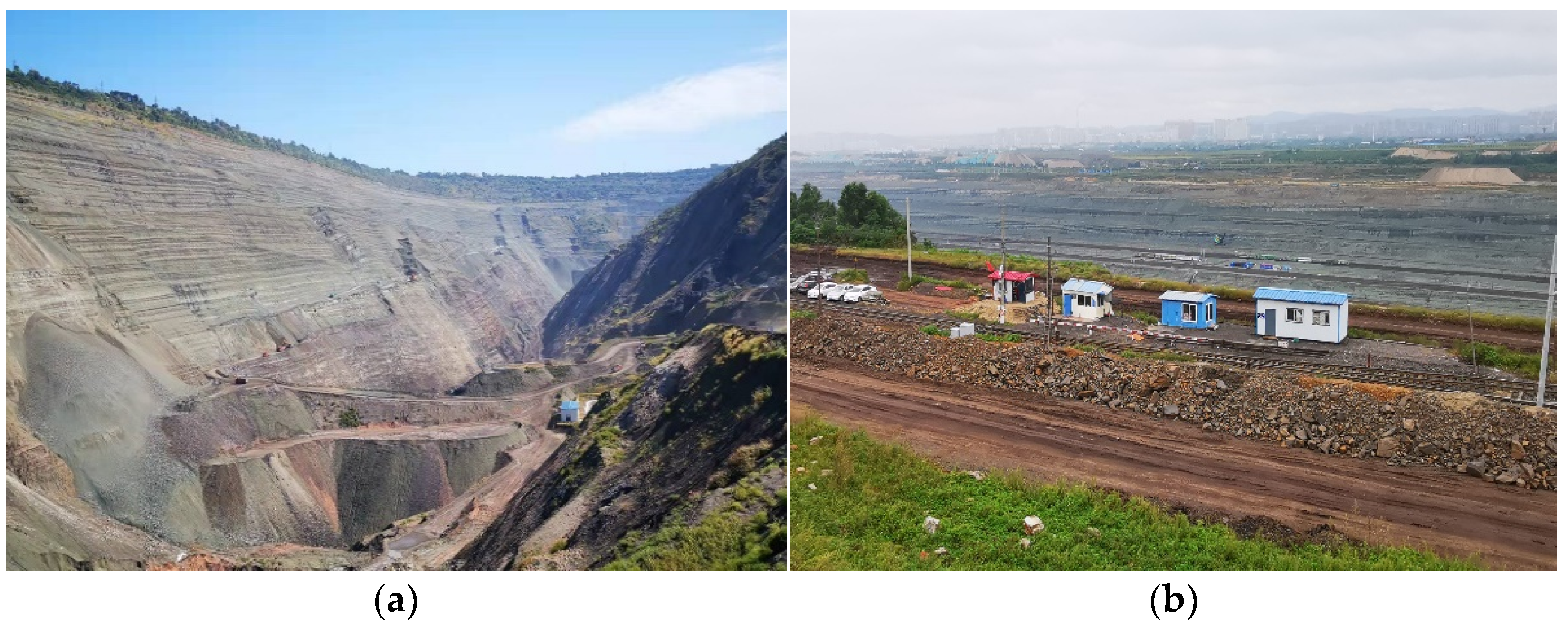
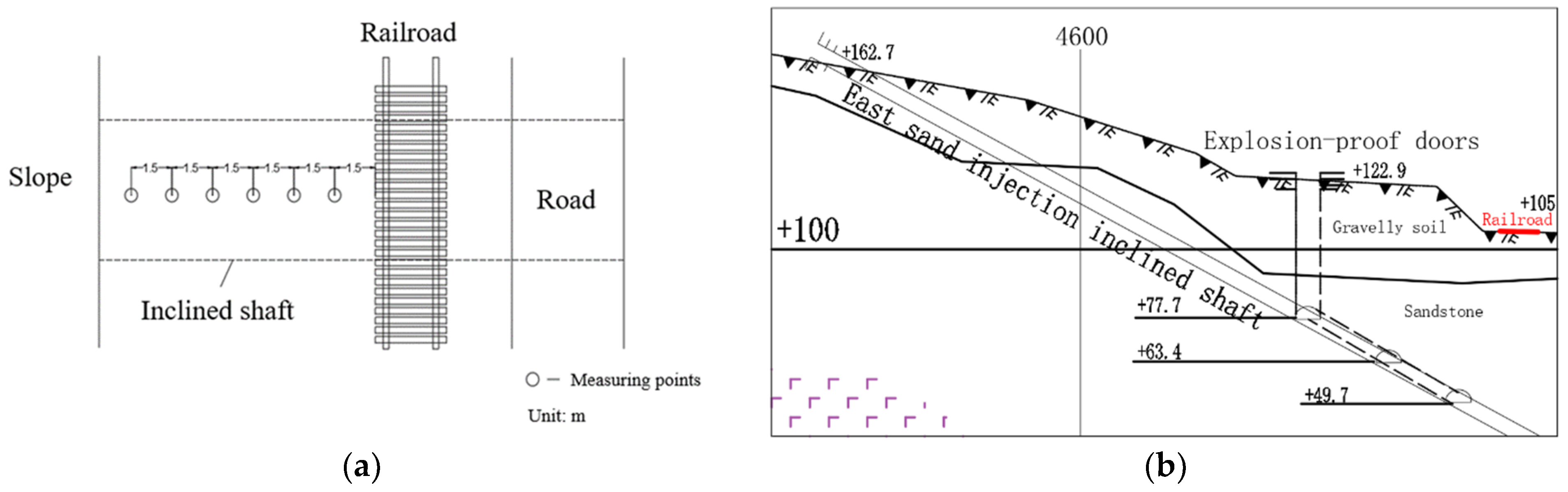
2.1. Project Overview

The east exhaust inclined shaft and east sand injection inclined Shaft of Laohutai Mine are located at the southern foot of the East Open Pit in Dongzhou District, Fushun City, near the top of the slope, with an average elevation of 125 m. The east sand injection inclined shaft is mainly used for sand injection in the mine workings and fire-fighting water injection system. The east exhaust inclined shaft is used to exhaust air from the east wing of the mine. Since the ventilation method of the mine is diagonally extracted from both wings, the mine’s exhaust shafts are arranged in both wings of the mine, and the coal seam of the Laohutai mine is inclined from south to north, using a combination of inclined and vertical development. From a macro-perspective, the Fushun Coalfield is located in a basin surrounded by the remaining veins of the Changbai Mountains and buried under the alluvial plain of the Hun River. The flat alluvial plain is piled up under the foothills, and the boundary is obvious. The landform type in the area is hilly area with large topographic undulations, and the pit area is a terrace terrain formed by artificial transformation. The geological structure of the Fushun coalfield is relatively complex, with many faults and large folds, as shown in Figure 1a. Topsoil stripping work is currently underway on the slopes where the east exhaust inclined shaft and east sand injection inclined shaft are located. At the same time, two mine roads and a mining railroad are open to traffic above the inclined shaft, which has a certain impact on the stability of the inclined shaft, as shown in Figure 1b.
The regional geological structure of Fushun coalfield mainly includes the Swire Anshan Group, the Lower Cretaceous Longfengkan Group, the Cenozoic Old Tertiary, and the Fourth Series. According to the survey report, the slope where the inclined shaft is located is divided into three layers: quaternary artificial accumulation layer (Q4ml), with uneven thickness, generally 2–10 m, and an average of 4 m. The uppermost part is artificial accumulation of construction waste, which is mainly composed of broken stones, bricks, and a small amount of clay; quaternary residual slope accumulation layer (Q4dl + el), the thickness of this layer is uneven, generally 4–17 m, average 6 m. It is mainly composed of cohesive soil and gravel (sandstone) with yellowish-brown color and poor sorting and grinding round. The gravel diameter is generally 2–3 cm, and the maximum can reach 8 cm; the lithology of the sandstone formation of the Lizigou Group (E12l), the lithology of this layer is sandstone, with local green curtain stone. Its direction is consistent with the direction of the coal in this layer, with a dip angle of 30–37°, generally 35°, and its tendency is basically consistent with the tendency of the side slope, with a tendency of 33°. That is, the south formation is in the state of cascade, which is not good for the stability of the slope.

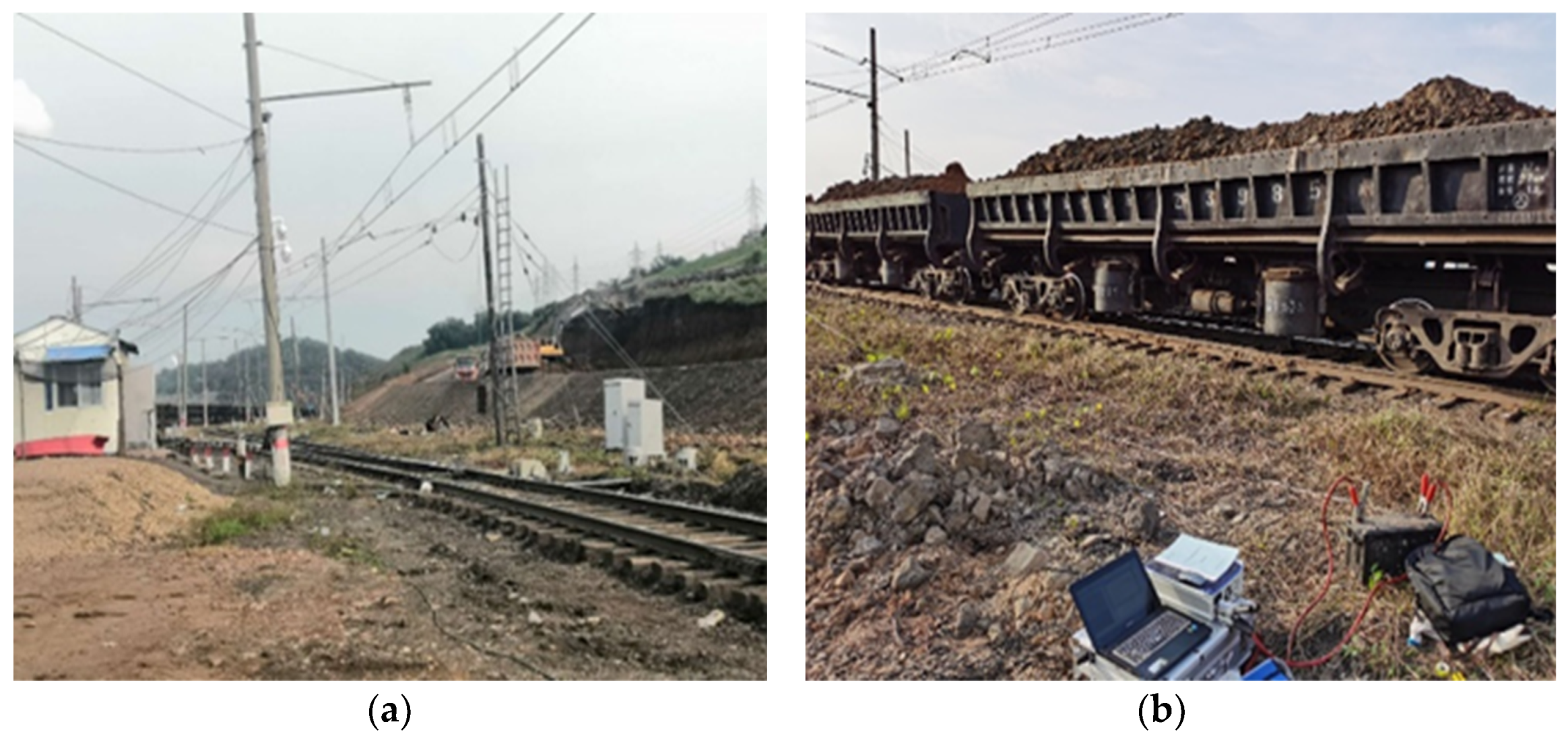
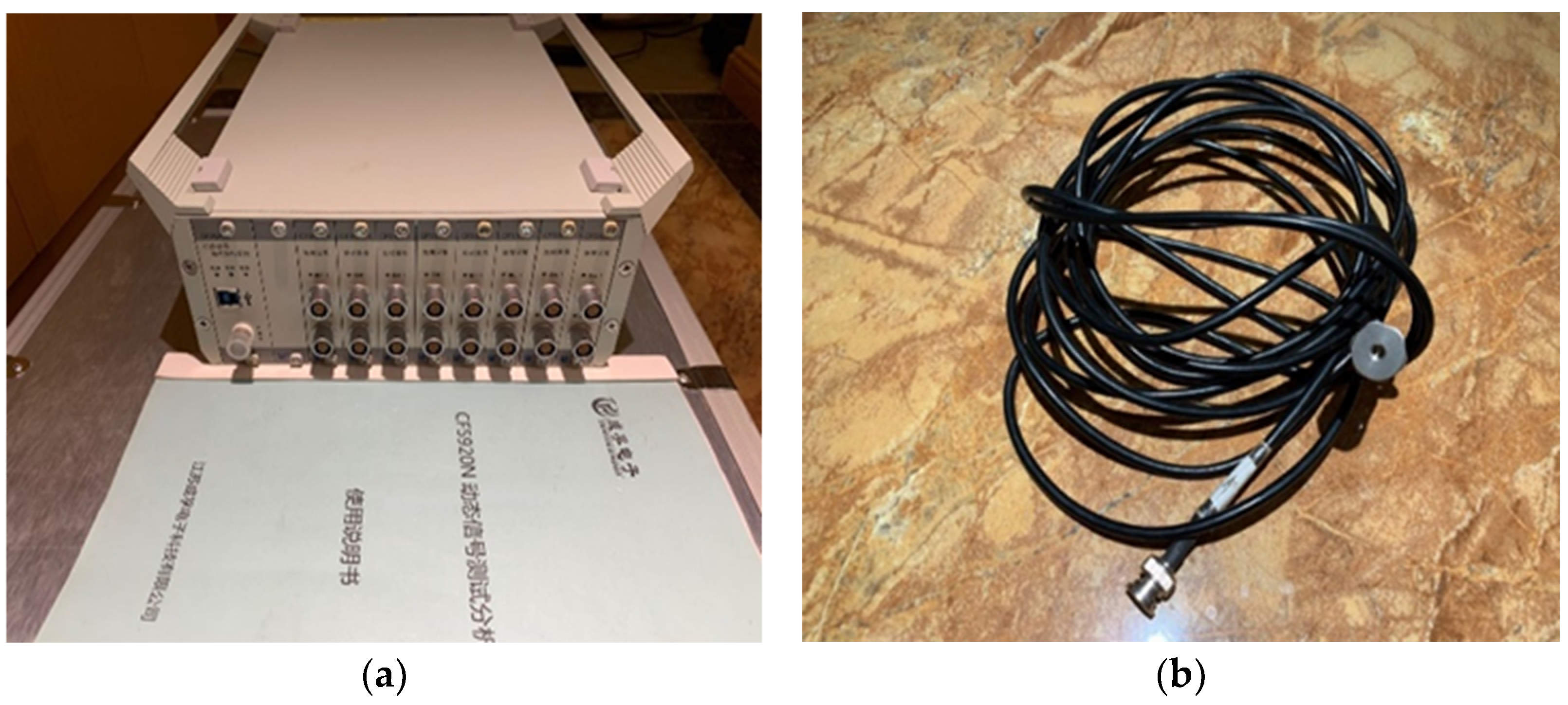
2.2. Field Monitoring

The monitoring section is located at the east sand injection shaft of LaoHuTai, and the test site is mainly quaternary artificial accumulation layer. The measuring point arrangement is shown in Figure 2, defining horizontal direction vertical to the railway extending as horizontal (x), horizontal direction parallel to the railway extending as vertical (y) and vertical to the railway as vertical (z). Six measuring points are set along the horizontal direction, with a spacing of 1.5 m, for each measuring point, monitoring both the horizontal and vertical vibration acceleration.
Each measuring point uses a 173A500 acceleration sensor (with a monitored acceleration range: −10 g–+10 g). The CF5920N dynamic signal test analyzer is used for the data acquisition, as shown in Figure 3. CF5920 dynamic signal test and analysis system and SeismoSignal vibration spectrum analysis system were used for data processing. In this test, the monitoring sampling frequency is 1000 Hz.
The slope location and monitoring site of the railway are shown in Figure 4.

2.3. Numerical Simulation

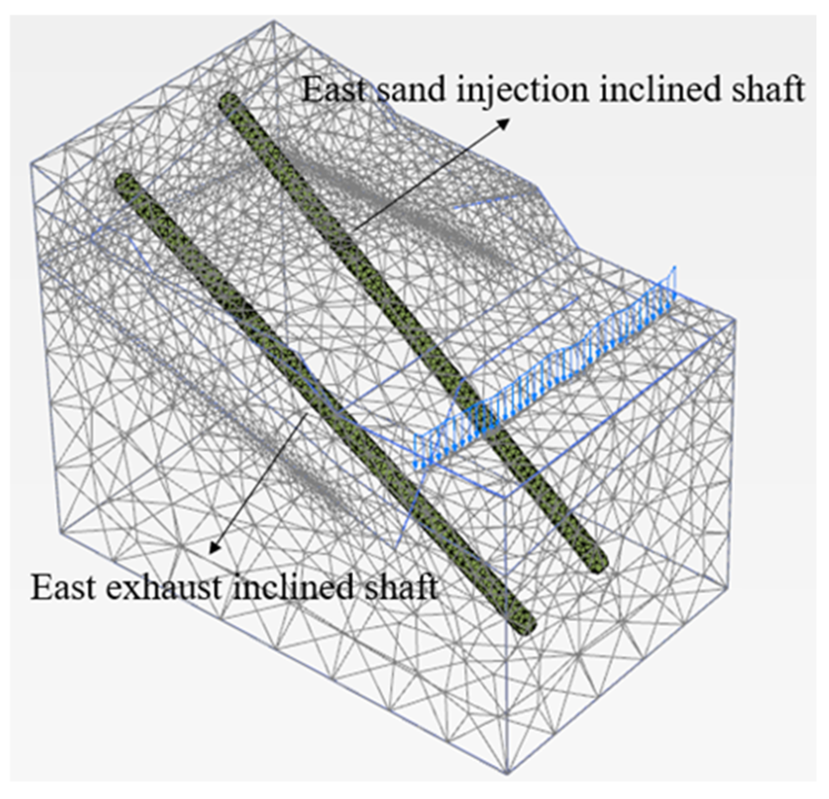
2.3.1. Calculation Model and Parameters

PLAXIS 3D program is a 3D finite element program for geotechnical deformation and stability analysis. With the development of PLAXIS, it has been gradually improved into a set of software with solid theoretical foundation, friendly interface, and strong logic applicable to most geotechnical engineering fields. It is successfully applied to the computational work of tedious and time-consuming non-linear finite elements in geotechnical engineering. In order to fully reflect the dynamic response of slope and roadway under train dynamic load, PLAXIS 3D software was used for simulation analysis, and the model size of 200 m × 120 m × 145 m was taken to simulate the area with strong human engineering activities, great influence on slope stability, and possible influence on the safety of underground inclined shaft. As shown in Figure 5, the length of the model is 200 m, and the width is 120 m. The value of the model height depends on the result of geological exploration, considering the effect on the epidote layer and the depth of the inclined shaft—145 m is taken. According to the current diagram of open-pit mine, the cross-sectional diameter of both inclined shafts is 6 m, the length of the inclined shaft is 230 m, and the wall thickness is 0.45 m. Two shafts successively go through the upper complex gravel soil layer, sandstone layer, chlorinated weak layer and bottom sandstone layer. The calculation model is shown in Figure 5, dividing 81,286 units and 123,035 grids.
All the constitutive model of the soil adopts the ideal elastic-plastic model based on the Moore-Coulomb yield criterion and the non-associated flow rule. Two inclined shafts are simulated using plate elements. The bottom surface of the slope calculation area adopts fixed constraints, the model sides are normal fixed constraints, and the others are free boundaries. In practice, the vibration wave propagates all the way along the semi-infinite soil, but after setting the boundary artificially, there is a wave reflection at the boundary, and the reflected-back wave affects the analysis result of vibration response. In order to counteract the effect of reflection of such waves at the boundary on vibration analysis, special measures are taken at the boundary to set up a viscous boundary. Since the theory of viscous boundary conditions is mature and widely used, most of the finite element software provides the boundary condition of viscous boundary; therefore, the viscous boundary condition in PLAXIS 3D is also used in the dynamic calculation after the dynamic load of the train is applied. The displacement of the slope model under the stability analysis of the rock mass. According to the results of the field geological survey, the rock stratification is not obvious, and the rock quality is good; therefore, the suppression of the rock mass layers is not considered in the simulation. This is an elastic-plastic dynamic calculation and does not take into account the dynamic coefficients in the proposed hydrostatic method. The Rayleigh damping coefficients α of 0.1 and β of 0.008 were obtained from the indoor tests. The strata analyzed in this slope are mainly mixed fill, gravel soil, and sandstone with weak layer in the middle section of sandstone, and the physical and mechanical parameters of the stratum are shown in Table 1: where γ u n s a t is the unsaturated weight, γ s a t is the saturated weight, E is the effective modulus of elasticity, v is the Poisson’s ratio, c is the cohesion, and φ is the friction angle.
The schematic diagram of train dynamic load and two inclined shaft position in the model is shown in Figure 6.

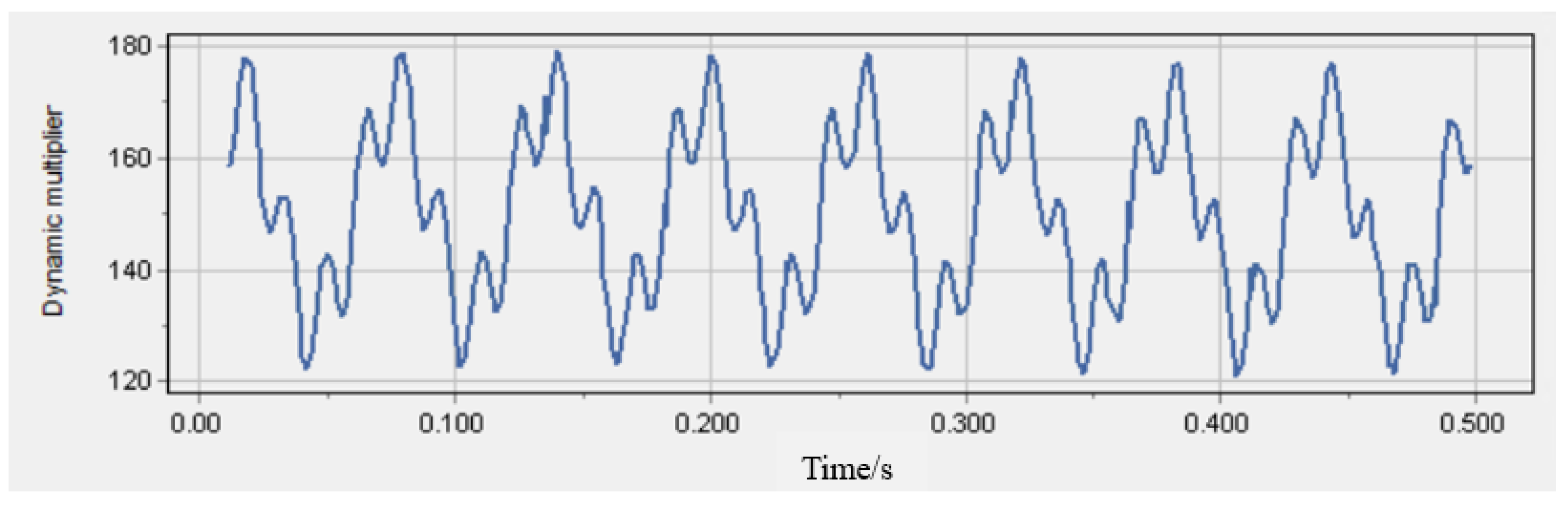
2.3.2. Application of the Train Load

Based on the train vibration mechanism, the superposition coefficient and dispersion coefficient are introduced to modify the existing train rail load expression. The revised load expression is:
F ( t ) = k 1 k 2 ( A 0 + A 1 sin ω 1 t + A 2 sin ω 2 t + A 3 sin ω 3 t )
where A0 is the static wheel load; A1, A2, and A3 are the peak vibration load corresponding to the circular frequency of rail vibration ω1, ω2, and ω3, respectively; k1 is the superposition coefficient of wheel-rail action, taking the value range of 1.2–1.7; k2 is the dispersion coefficient of wheel-rail action, taking the value range of 0.6–0.9.
Let the under-spring mass of the train be m, and then the corresponding vibration load Ai is:
A i = m α i ω i 2
where i = 1, 2, 3 corresponds to the three control conditions of smoothness, power surcharge load on the line, and waveform wear. α i is the typical positive vector, and ω i is the vibration circle frequency. The formula for ω i is:
ω i = 2 π v L i
where L i is the wavelength corresponding to α i , v is the travel speed.
Based on Equations (1) and (2), the time curve of train vibration load at 60 t axle weight and running speed of 15 km/h is calculated and shown in Figure 7.

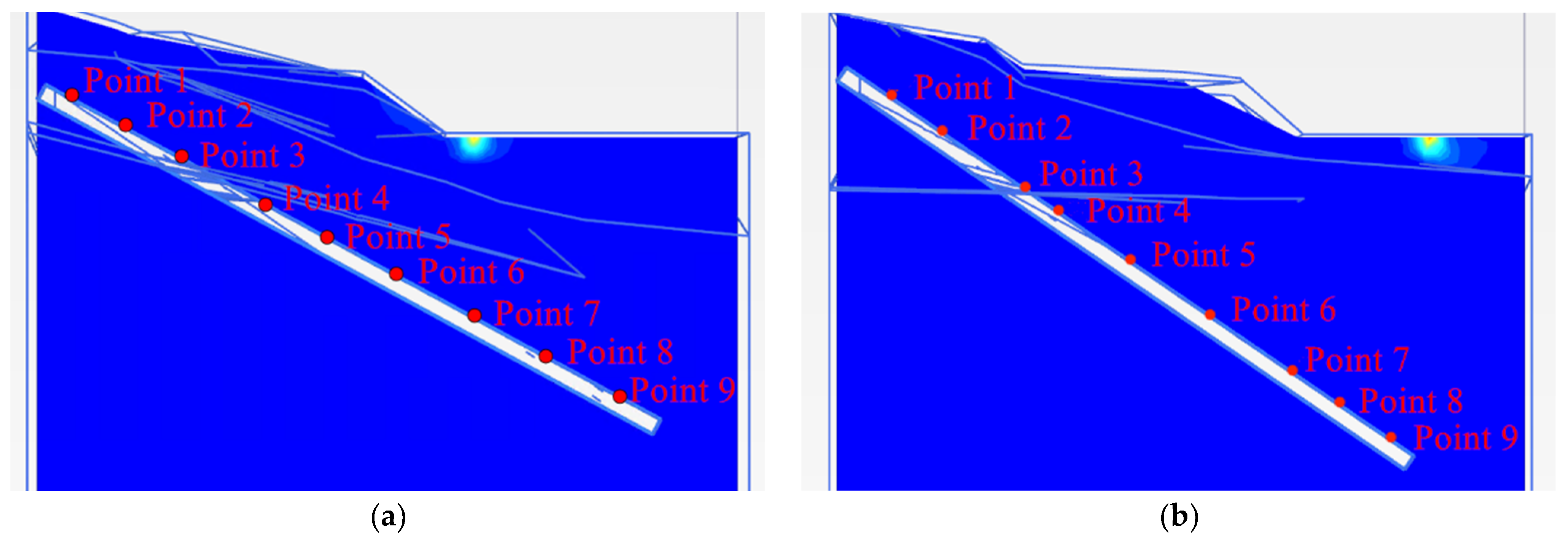
2.3.3. Distribution of Inclined Shaft Survey Points

In order to study the safety of east exhaust inclined shaft under train load, the displacement and acceleration of east exhaust inclined shaft and east sand injection inclined shaft were simulated by using PLAXIS 3D software. A total of 9 measuring points are arranged at each inclined shaft, and the measuring points are distributed from bottom to top. Considering that the roadway crosses the epidote weak layer, one measuring point is arranged up and down the layer, as shown in Figure 8.

3. Results and Discussion

3.1. Monitoring Result

The monitoring sampling frequency is 1000 Hz; the speed of the no-load train is 20 km/h; the weight is 30 t/section; and the speed of the full-load train is 15 km/h, and the weight is 60 t/section. Define the acceleration characteristic value: the maximum absolute acceleration, the maximum recorded absolute value of the acceleration at the same measuring point at each moment, and describe the maximum amplitude of the vibration acceleration at the measuring point when each train passes, and x, y, z direction is recorded as | a x | m a x | a y | m a x | a z | m a x . Based on the monitoring statistical results and data processing, the vibration acceleration reaction features were analyzed as follows: The surface vibration caused by three no-load trains and three fully loaded trains was monitored. Figure 9 shows the measured value of vertical and horizontal acceleration time curve at the surface of 1.5 m from the track under 60 t axle heavy-loaded train 15 km/h.
The acceleration and the track distance curves under different operating conditions are shown in Figure 10 and Figure 11.
From the Figure 10 and Figure 11, the characteristic values of horizontal and vertical acceleration decrease with the increase in distance from the measurement point, and the characteristic values of horizontal acceleration are less than 0.04 g, and vertical acceleration are less than 0.05 g at 9 m from the rail. The vibration response caused by a fully loaded train is obviously larger than that of an unloaded train; the decay speed of vibration caused by an unloaded train is obviously slower than that of a fully loaded train due to the faster driving speed. The vibration response caused by a fully loaded train is significantly larger than that of an unloaded train; the decay rate of vibration caused by an unloaded train is significantly slower than that of a fully loaded train due to its faster travel speed. This indicates that the train load and speed have an effect on the vibration response. Both horizontal and vertical acceleration eigenvalues decay significantly with increasing distance from the measurement point.

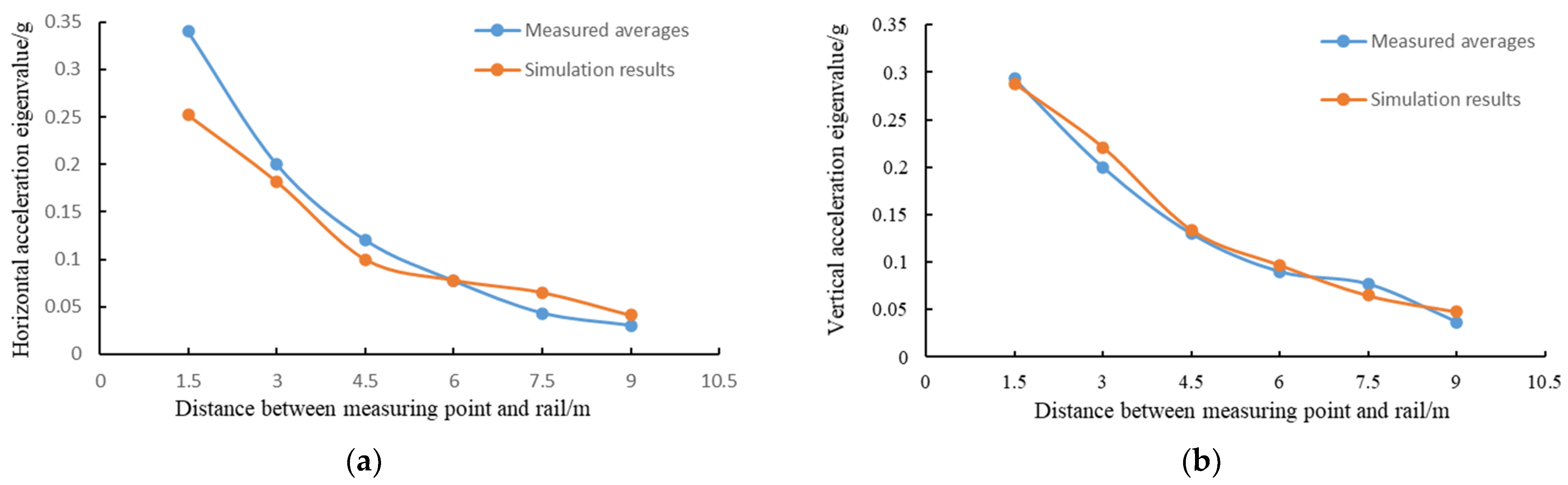
3.2. Model Correctness Verification

To verify the finite element model, the numerical results of the train dynamic load model are compared with the field measurements of the fully loaded train, as shown in Figure 12. It can be seen from the figure that the horizontal and vertical acceleration eigenvalues of each measuring point in the numerical calculation model are basically the same as the measured value, indicating that the finite element model is feasible and correct.
To study the dynamic response characteristics of the inclined shaft under the train load, the surface horizontal and vertical acceleration features above the east exhaust inclined shaft are simulated by the finite element model. The simulation results are shown in Figure 13.
It can be seen from the figure that the decay law of the acceleration eigenvalues is roughly the same as the measured results, which both show a decreasing trend. The maximum horizontal acceleration of 0.23 g, vertical acceleration of 0.32 g is close to the measured results. It is considered that the establishment of this model is correct and feasible to analyze the dynamic response of the slope and inclined shaft.

3.3. Numerical Calculation Results and Analysis

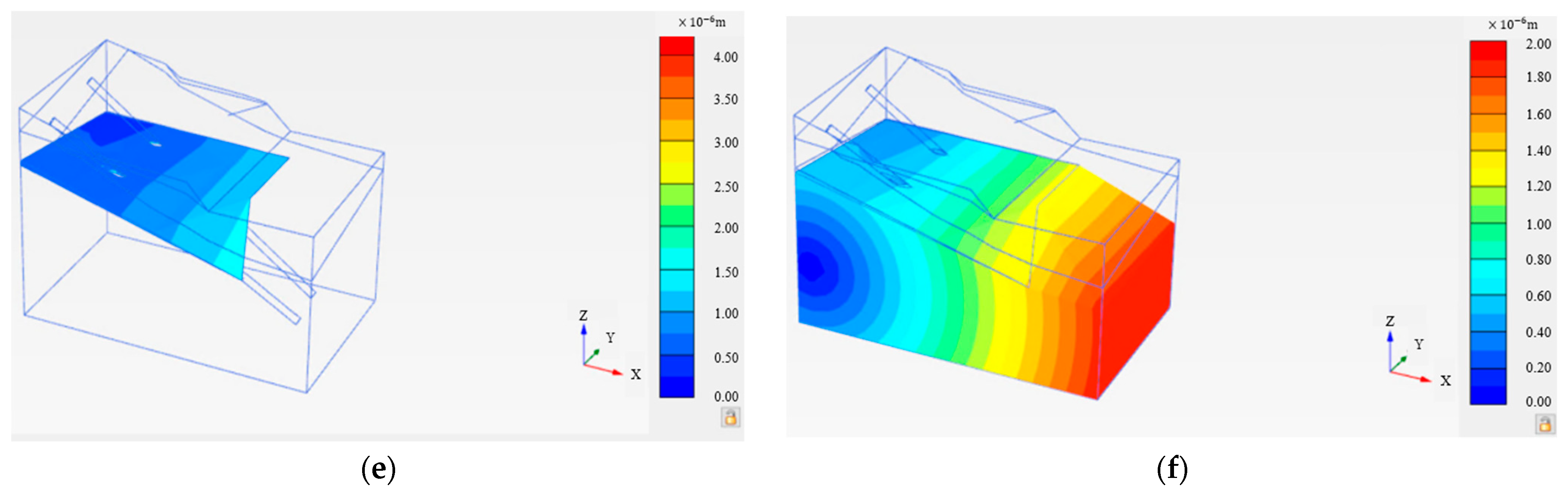
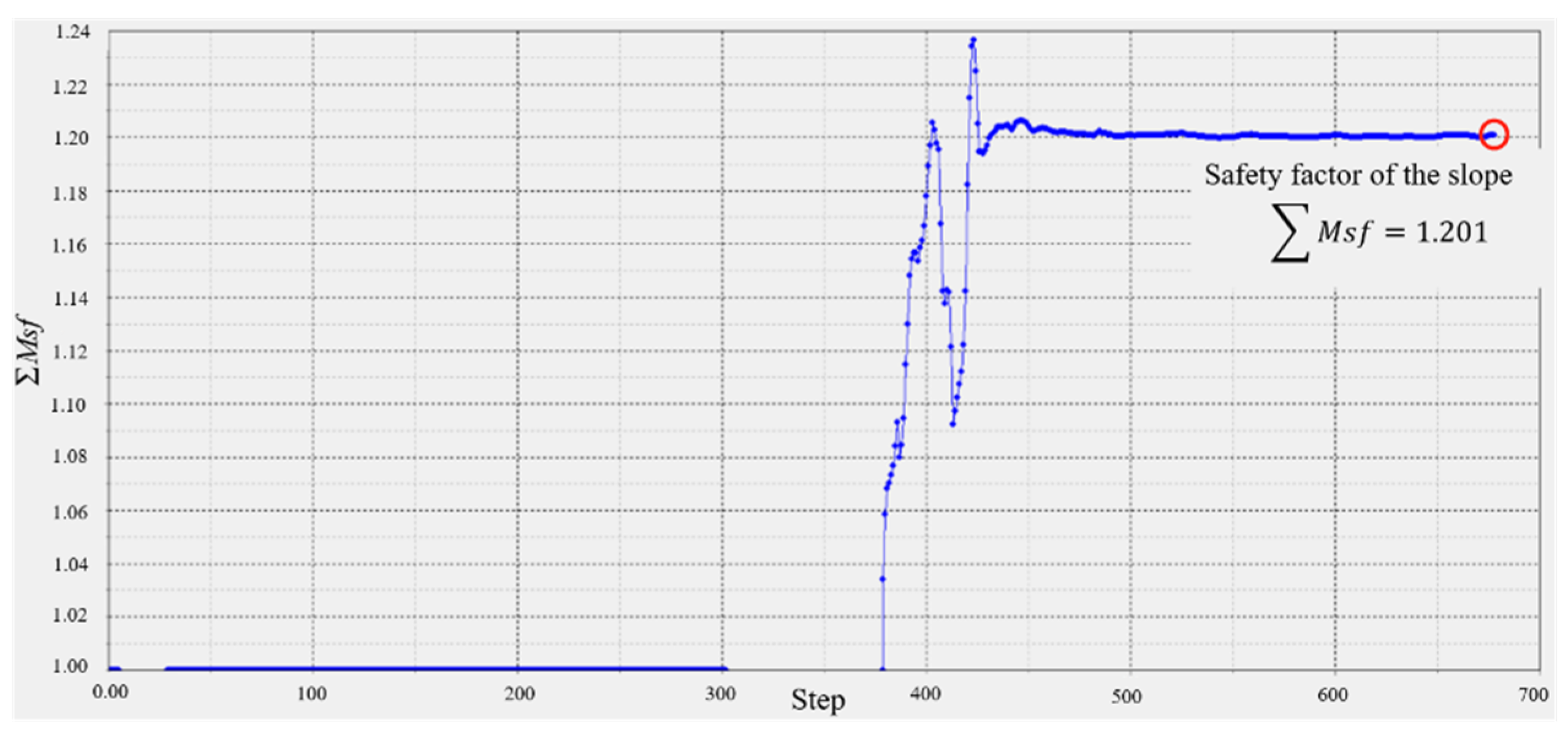
3.3.1. Slope Stability Analysis

After applying train load, the displacement of slope is shown in Figure 14 below.
The simulation results show that the maximum displacement of the slope is 5 mm and is directly below the train track; the miscellaneous fill layer on the side slope is only 0.5 mm. Considering that the distance between the slope and the dynamic load of the train is far, there is no landslide or damage in the soil. Both the internal dangerous epidote weak layer and the whole sandstone are less than 0.1 mm in displacement under the action of the train dynamic load, which can be ignored. Thus, the overall slope displacement under the dynamic load is very small, and the soil body does not suffer any damage.
The safety factor of the slope is derived from the strength-fold subtraction, which shaft unifies the strength reserve safety factor with the overall stability safety factor of the slope. The essence is that the initial shear strength τ of the slope decreases as the initial value, in order to find the shear strength value τ ‘(which just makes the slope in a critical unstable state and is referred to as critical shear strength). The critical shear strength value is:
τ = τ F = c + σ · tan φ F = c F + σ tan φ F
Correspondingly, the reduced shear strength parameters are: c and φ
c = c F
φ = arctan ( tan φ F )
The slope safety factor calculated by this model is shown in Figure 15 below.
The safety coefficient of the slope finally converges to 1.201; that is, the safety coefficient of the slope is 1.201, and according to the Design Standard for Slope Engineering of Coal Industry Open-Pit Mine GB 51289-2018, the safety coefficient of the slope is not less than 1.05. Thus, it can be judged that the slope is stable under the action of traffic load.

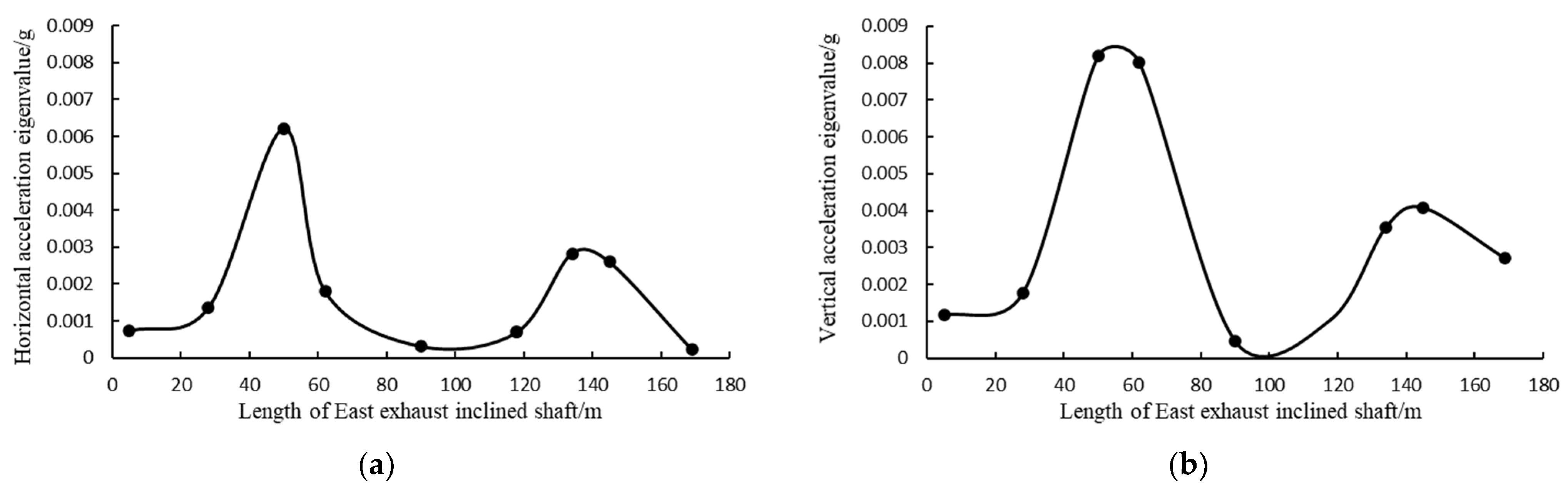
3.3.2. Dynamic Response of East Exhaust Inclined Shaft

Under the action of the train dynamic load, the displacement of the inclined shaft and the acceleration response of the various measuring points on the inclined shaft are mainly considered. The displacement cloud diagram of the east exhaust inclined shaft is shown in Figure 16 below.
Under the train load, the horizontal displacement peak of the east exhaust inclined shaft is 0.02 mm and located at the top of the east exhaust inclined shaft; the inclined shaft has the top-right (x positive) deformation trend under dynamic load; the vertical displacement peak of the east exhaust inclined shaft is 0.03 mm and is also at the top of the inclined shaft; and the bottom-left (x negative) deformation trend of the inclined shaft is under dynamic load. Overall, train load vibration has little impact on the east exhaust inclined shaft displacement. Its vertical and horizontal displacement are less than 0.1 mm, and the east exhaust inclined shaft is deflected negligibly under the influence of the dynamic train load.
The acceleration characteristic values of each measuring point of east exhaust inclined shaft are shown in Table 2.
The acceleration characteristic value of the inclined shaft are shown in Figure 17.
As it can be seen from Table 2, in general, the acceleration characteristic values of each measurement point are small, and the maximum values of horizontal and vertical acceleration are 6.21 × 10⁻³ and 8.19 × 10⁻³ g, respectively, at measurement point 3, i.e., the upper part of the diagonal shaft going down through the weak layer of epidote. As can be seen from Figure 18, there are two significant increases in the characteristic value pattern of acceleration in each direction: the first one is a significant increase in the peak value when going down through the weak layer, and the second one is at the point directly below the load. Further, the horizontal acceleration of the rest of the inclined shaft measurement points is stable at 1 × 10⁻³ g, and the vertical acceleration is stable at 1–3 × 10⁻³ g. In general, the effect of train load on the safety of the east exhaust inclined shaft is relatively small.

3.3.3. Dynamic Response of East Injection Inclined Shaft

Under the action of the train dynamic load, the displacement of the inclined shaft and the acceleration response of the various measuring points on the inclined shaft are mainly considered. The displacement cloud map of the east injection shaft is shown in Figure 18 below.
Under the action of train load, the horizontal displacement of the east sand inclined shaft is 0.018 mm and located at the top of the inclined shaft, slightly offset (x direction) within 0.018 mm; given the vertical displacement of 0.028 mm, at the bottom of the inclined shaft, there is overall sinking trend, but the sinking amount is within 0.03 mm. In general, train load vibration has little impact on the displacement of the east injection inclined shaft, and its vertical and horizontal displacement are less than 0.1 mm and are negligible under the influence of train dynamic load.
The acceleration characteristic values of the east exhaust inclined shaft are shown in Table 3.
The acceleration characteristic value of the inclined shaft are shown in Figure 19.
In general, the acceleration characteristic values of each measurement point are small, and the maximum values of horizontal and vertical acceleration are 6.98 × 10⁻³ and 4.85 × 10⁻³ g, respectively, also at measurement point 3, which is the upper part of the inclined shaft down through the weak layer. The horizontal and vertical accelerations change in a similar pattern, and both have a significant increase at measurement point 3, i.e., measurement point 7, which is directly below the load. The horizontal and vertical acceleration time curves both increase to the maximum peak before 0.1 s. The peak value increases significantly through the weak layer, and the acceleration increases at the measurement point below the load, while the horizontal acceleration at the rest of the inclined shaft measurement points is stable at 1–2 × 10⁻³ g, and the vertical acceleration is stable within 1 × 10⁻³ g. In general, the effect of train load on the safety of the east sand injection inclined shaft is relatively small.

4. Conclusions

Most of the previous studies by scholars on inclined shafts lie in underground mines, and there are fewer studies on open-pit mines. As one of the larger open-pit mines in Asia, the scale of the inclined shaft in Laohutai mine is also rare in the world. Unlike previous scholars, the dynamic load in this study is the dynamic load generated during the train travel, not the small-scale vehicle load. In this study, through site monitoring and power response analysis on the slope of the east sand injection inclined shaft and the east exhaust inclined shaft, the following conclusions are drawn:
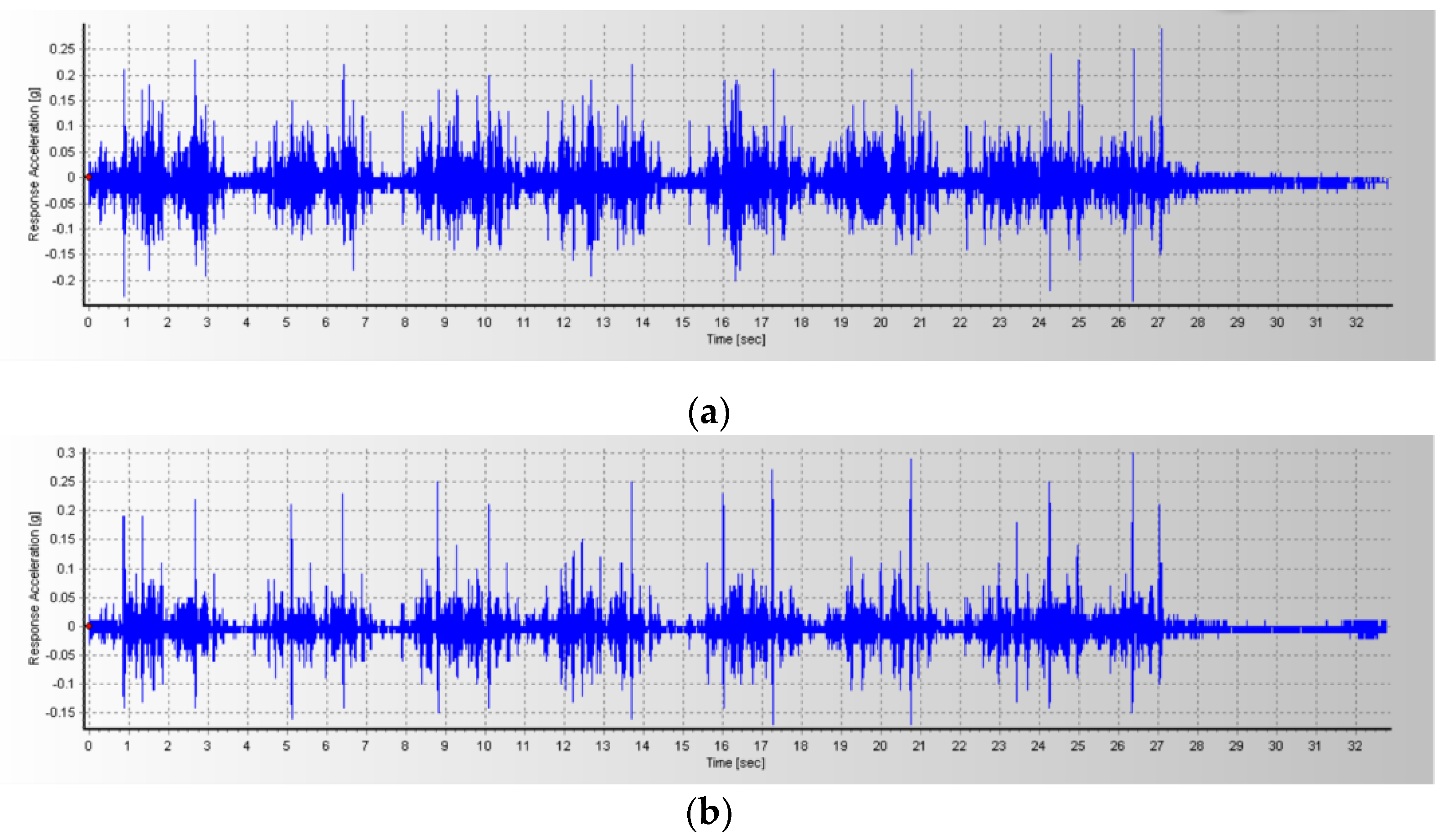
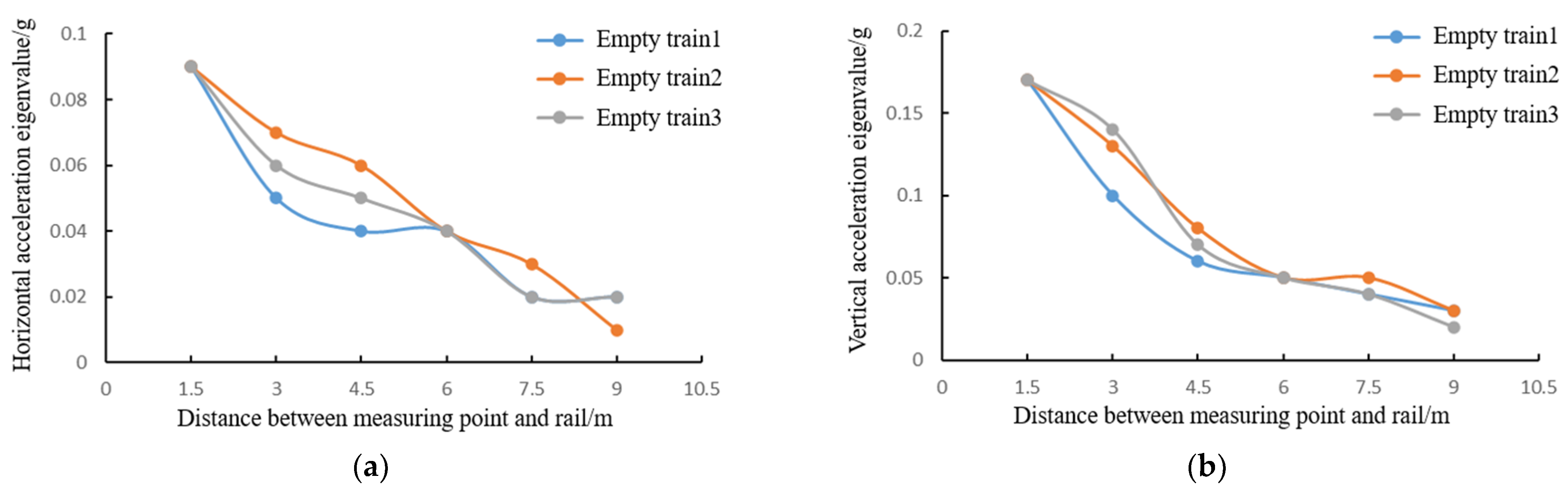
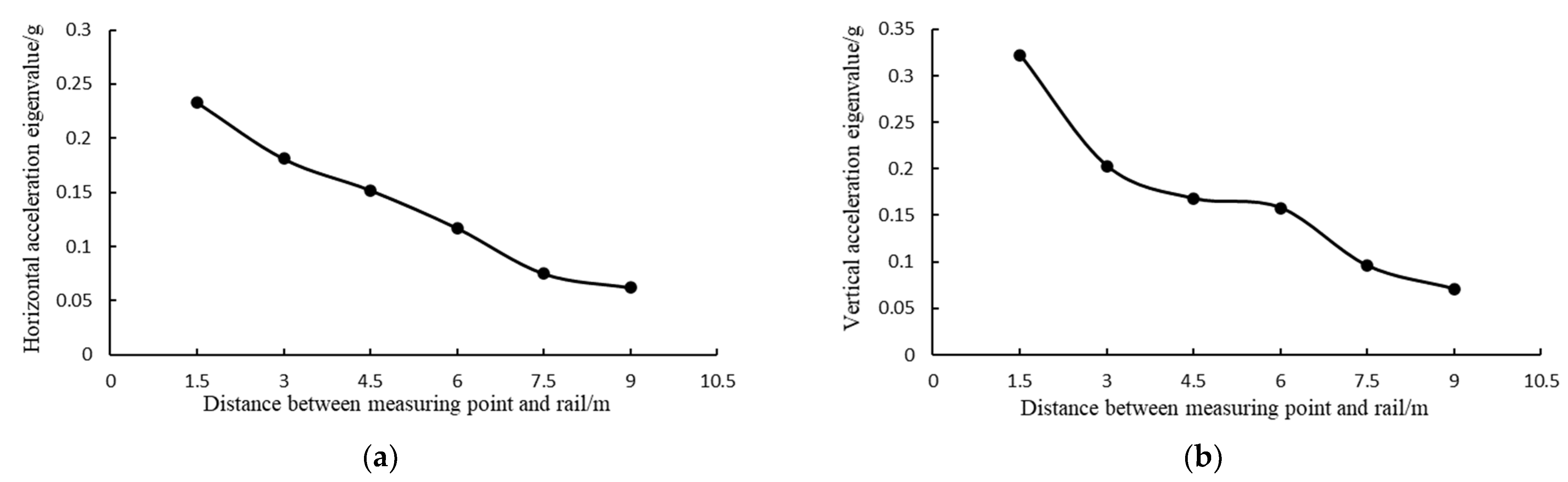
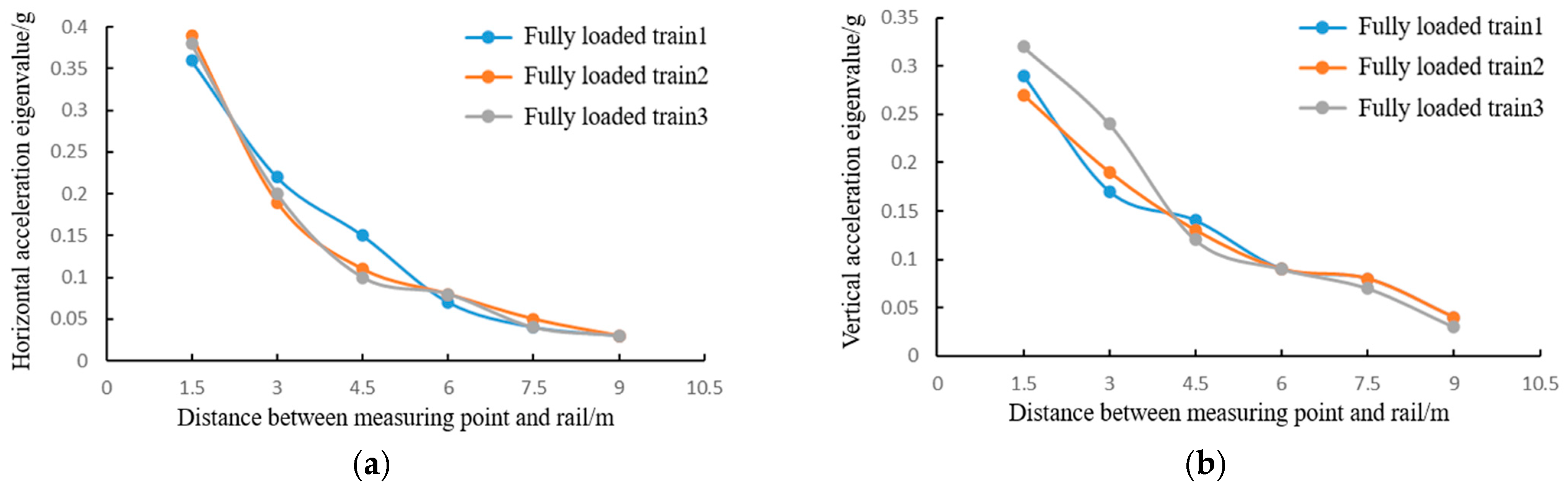
  • The vibration response caused by the full-load trains is significantly greater than the no-load trains. The attenuation speed of the vibration caused by the no-load trains is significantly slower than the full-load trains, which shows that the train load and speed have an impact on the vibration response. Both the horizontal and vertical acceleration eigenvalues decay significantly with the distance of the measuring point;
  • Under the action of dynamic load, the maximum displacement of the slope appears in the gravel soil layer, 5 mm, and directly below the train track. The side slope and each soil layer are less than 1 mm soil. The safety factor of the slope under the action of the dynamic load is 1.201.
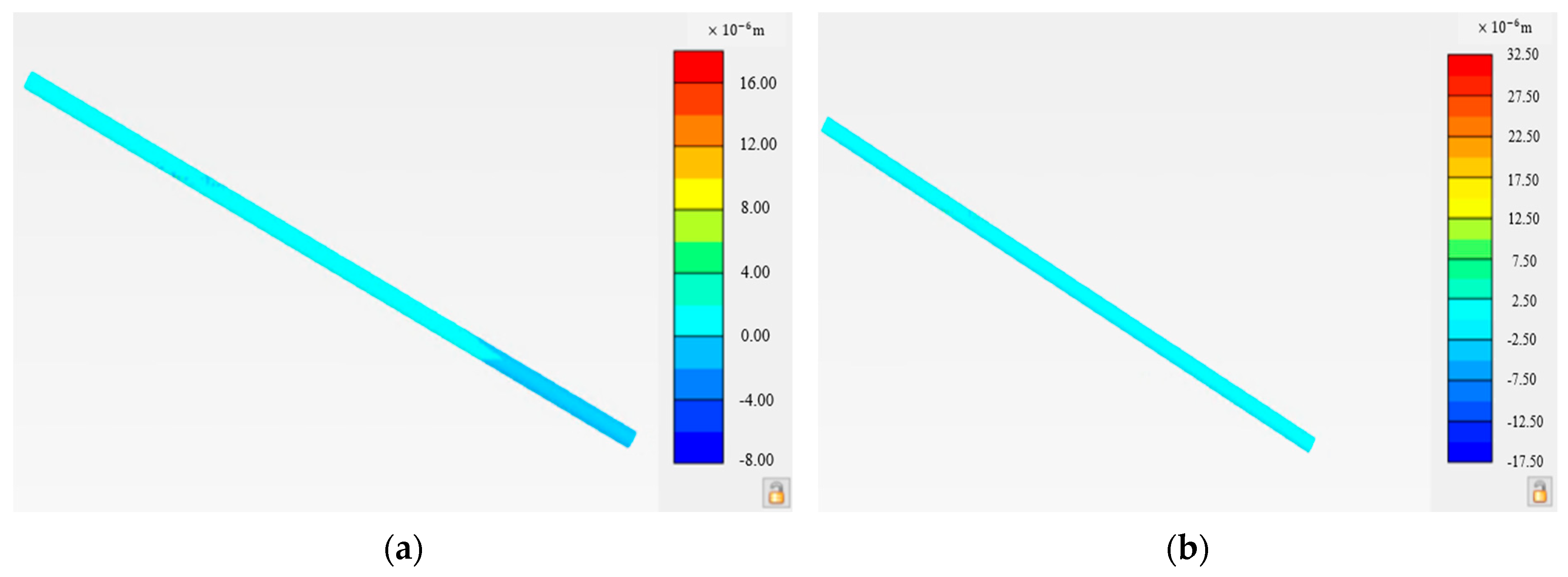
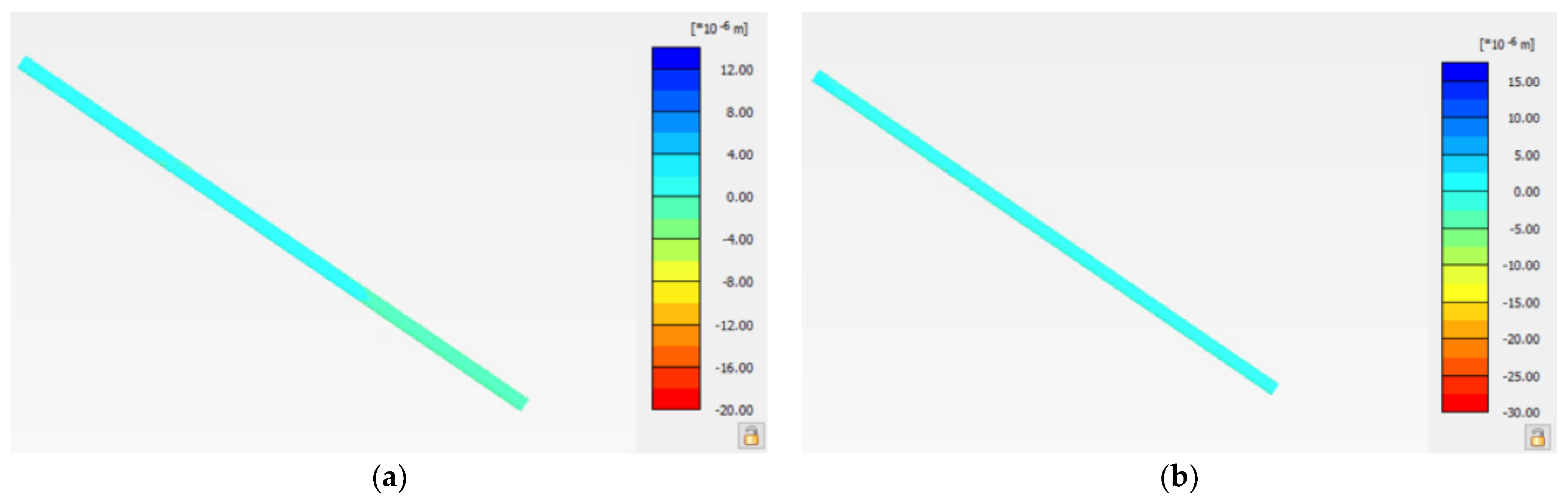
  • The offset of east exhaust and east sand injection inclined shaft caused by train dynamic load is less than 0.1 mm and is far from the dynamic load, and the displacement caused by vibration is negligible;
  • The acceleration response law of east exhaust inclined shaft and east sand injection inclined shaft is consistent. Both the horizontal and vertical acceleration reached the maximum at the epidote weak layer, and the acceleration increased significantly directly below the load. The maximum horizontal acceleration of the east exhaust inclined shaft is 6.21 × 10⁻³ g, with a vertical acceleration of 8.19 × 10⁻³ g; the horizontal acceleration of the east injection inclined shaft is 6.98 × 10⁻³ g, with a vertical acceleration of 4.85 × 10⁻³ g. Overall, the inclined shaft acceleration response caused by the train vibration is small. Therefore, this test has a certain guiding significance for the selection of the through speed and load of trains on open-pit mines with inclined shafts and also provides some reference for the stability of the slopes of open-pit mines under the action of train loads.

Author Contributions

Funding acquisition, Y.W.; Project administration, Y.W.; Resources, Y.W., F.-W.Y., Z.-X.W., H.Z., K.M. and X.-J.L.; Software, S.-T.N.; Writing—original draft, Y.W. and S.-T.N.; Writing—review & editing, S.-T.N. All authors have read and agreed to the published version of the manuscript.

Funding

This study was funded by China Coal Technology Engineering Group (Grant No. wk004-2019 and No. 2018-2-ZD004).

Data Availability Statement

Data presented in this article are available at request from the corresponding author.

Acknowledgments

We wish to acknowledge the staff of Fushun Laohutai Mine, including Chief Engineer Fa-Wu Yang, and the team of Yu-Min Chen from Hohai University.

Conflicts of Interest

The authors declare no conflict of interest.

References

  1. Valero, A.; Valero, A. Physical geonomics: Combining the exergy and Hubbert peak analysis for predicting mineral resources depletion. Resour. Conserv. Recycl. 2010, 54, 1074–1083. [Google Scholar] [CrossRef]
  2. Haque, N.; Hughes, A.; Lim, S.; Vernon, C. Rare earth elements: Overview of mining, mineralogy, uses, sustainability and environmental impact. Resources 2014, 3, 614–635. [Google Scholar] [CrossRef] [Green Version]
  3. Cheskidov, V.I.; Norri, V.K. Stripping with direct dumping in Kuzbass open pit mines: The current state and prospects. J. Min. Sci. 2016, 52, 725–731. [Google Scholar] [CrossRef]
  4. Cheskidov, V.I.; Bobyl’sky, A.S. Technology and Ecology of Dumping at Open Pit Mines in Kuzbass. J. Min. Sci. 2017, 53, 882–889. [Google Scholar] [CrossRef]
  5. Zaitseva, A.A.; Cheskidov, V.I.; Zaitsev, G.D. Effect of the mining sequence on the internal dump capacity in an open pit. J. Min. Sci. 2007, 47, 317–323. [Google Scholar] [CrossRef]
  6. Meng, X.T.; Yu, S.Z.; Li, Z.F.; Wen, H.X. The slope monitoring method research. Appl. Mech. Mater. 2014, 501–504, 834–838. [Google Scholar] [CrossRef]
  7. Selyukov, A.V. Technological significance of internal dumping in open pit coal mining in the Kemerovo Region. J. Min. Sci. 2015, 51, 879–887. [Google Scholar] [CrossRef]
  8. Bakhaeva, S.P.; Gogolin, V.A.; Ermakova, I.A. Calculating stability of overburden dumps on weak bases. J. Min. Sci. 2016, 52, 454–460. [Google Scholar] [CrossRef]
  9. Wajs, J. First experience with Remote Sensing methods and selected sensors in the monitoring of mining areas—A case study of the Belchatow open cast mine. E3S Web Conf. 2018, 29, 23. [Google Scholar] [CrossRef] [Green Version]
  10. Selyukov, A.; Gerasimov, A.; Grishin, V. The Results of Mining and Geometric Analysis in Open Pit Mining of Promising Kuzbass Coal Deposits with Block System. E3S Web Conf. 2020, 174, 1020. [Google Scholar] [CrossRef]
  11. Cao, C.; Feng, J.; Tao, Z. Start-up mechanism and dynamic process of landslides in the full highwaste dump. Water 2020, 12, 2543. [Google Scholar] [CrossRef]
  12. Ye, H.; Wu, K.; Wang, J. Stability analysis about slope of Open pit Mine based on fuzzy synthetic evaluation. Adv. Mater. Res. 2012, 396–398, 2370–2374. [Google Scholar] [CrossRef]
  13. Zhu, M.; Ma, C.; Tang, R.; Zhang, R.; Li, T.; Wang, Y.; Liu, J. Slope stability analysis of open pit mine based on finite difference method. In Proceedings of the 2nd International Conference on Information and Computing Science, Manchester, UK, 21–22 May 2009; pp. 208–211. [Google Scholar] [CrossRef]
  14. Sun, S.; Yang, H.; Li, C.; Zhang, B.; Miao, A.; Wang, M. The study on key issues of slope instability during turning open-pit into underground mining. Adv. Mater. Res. 2012, 594–597, 70–75. [Google Scholar] [CrossRef]
  15. Azhari, A.; Ozbay, U. Investigating the effect of earthquakes on open pit mine slopes. Int. J. Rock Mech. Min. Sci. 2017, 100, 218–228. [Google Scholar] [CrossRef]
  16. Plotnikov, E.; Kolesnikov, V.; Šimková, Z.; Demirel, N. Features of new sites designing on quarry fields of the existing open pit mines of Kuzbass. E3S Web Conf. 2020, 174, 1003. [Google Scholar] [CrossRef]
  17. Nunoo, S. Lessons Learnt from Open Pit Wall Instabilities: Case Studies of BC Open Pit Hard Rock Mines. J. Min. Sci. 2018, 54, 804–812. [Google Scholar] [CrossRef]
  18. Petrović, B.; Vujić, S.; Čebašek, V.; Gajić, G.; Ignjatović, D. Predictive analysis of slope stability of internal dumps in Tamnava–West field mine after flooding. J. Min. Sci. 2016, 52, 110–114. [Google Scholar] [CrossRef]
  19. Vyazmensky, A.; Stead, D.; Elmo, D.; Moss, A. Numerical analysis of block caving-induced instability in large open pit slopes: A finite element/discrete element approach. Rock Mech. Rock Eng. 2010, 43, 21–39. [Google Scholar] [CrossRef]
  20. Segalini, A.; Giani, G.P. Numerical model for the analysis of the evolution mechanisms of the Grossgufer rock slide. Rock Mech. Rock Eng. 2004, 37, 151–168. [Google Scholar] [CrossRef]
  21. Qian, Z.-W.; Jiang, Z.-Q.; Guan, Y.-Z.; Yue, N. Mechanism and Remediation of Water and Sand Inrush Induced in an Inclined Shaft by Large-Tonnage Vehicles. Mine Water Environ. 2018, 37, 849–855. [Google Scholar] [CrossRef]
  22. Yan, Q.; Li, B.; Zhang, Y.; He, C. In situ automatic monitoring and working state assessment of inclined shafts in coal mines. Proc. Inst. Civ. Eng. Geotech. Eng. 2021, 174, 390–405. [Google Scholar] [CrossRef]
  23. Voloshin, V.A.; Rib, S.V.; Petrova, O.A.; Belyaev, A.V. The choice of the site for inclined shaft and parameters of its stage-by-stage construction in the conditions of the Tersinsky coal region. IOP Conf. Ser. Earth Environ. Sci. 2018, 206, 012009. [Google Scholar] [CrossRef]
  24. Zevgolis, I.E. Geotechnical characterization of mining rock waste dumps in central Evia, Greece. Environ. Earth Sci. 2018, 77, 566. [Google Scholar] [CrossRef]
  25. Liu, C.; Gao, Y. Numerical simulation of slope stability analysis of open pit coal mine based on MIDAS/GTS. Appl. Mech. Mater. 2013, 256–259, 193–197. [Google Scholar] [CrossRef]
  26. Huang, J.; Duan, T.; Lei, Y.; Hasanipanah, M. Finite Element Modeling for the Antivibration Pavement Used to Improve the Slope Stability of the Open-Pit Mine. Shock Vib. 2020, 2020, 6650780. [Google Scholar] [CrossRef]
  27. Nie, L.; Li, Z.; Zhang, M.; Xu, L. Deformation characteristics and mechanism of the landslide in West Open-Pit Mine, Fushun, China. Arab. J. Geosci. 2015, 8, 4457–4468. [Google Scholar] [CrossRef]
  28. Sakantsev, G.G.; Cheskidov, V.I.; Zyryanov, I.V.; Akishev, A.N. Validation of Slopes of Access Roads in Deep Open Pit Mining. J. Min. Sci. 2018, 54, 77–84. [Google Scholar] [CrossRef]
  29. Abdellah, W.R.; Hussein, M.Y.; Imbabi, S.S. Rock slope stability analysis using shear strength reduction technique (SSRT)—Case histories. Min. Miner. Depos. 2020, 14, 16–24. [Google Scholar] [CrossRef]
  30. Abdellah, W.; Beblawy, M.; Mohamed, M. Evaluation of open pit slope stability using various slope angles and element types. Min. Miner. Depos. 2018, 12, 47–57. [Google Scholar] [CrossRef]
  31. Zairov, S.; Ravshanova, M.; Karimov, S. Intensification of technological processes in drilling and blasting operations during open-cut mining in Kyzylkum region. Min. Miner. Depos. 2018, 12, 54–60. [Google Scholar] [CrossRef] [Green Version]
Figure 1. Site picture of Laohutai Mine. (a) Schematic outline of the mine site; (b) road and railroad diagram of the mining area.
Metals 11 01681 g001
Figure 2. Monitoring location diagram. (a) Schematic diagram of the measuring point layout. (b) Cross-sectional view of monitoring location.
Metals 11 01681 g002
Figure 3. Monitoring instruments. (a) CF5920N dynamic signal test analyzer; (b) 173A500 Acceleration Sensor.
Metals 11 01681 g003
Figure 4. Field monitoring situation. (a) Location of the railway tracks; (b) monitoring site.
Metals 11 01681 g004
Figure 5. Calculation model diagram.
Metals 11 01681 g005
Figure 6. Schematic diagram of dynamic load and inclined shaft position.
Metals 11 01681 g006
Figure 7. Time range curve of train dynamic load.
Metals 11 01681 g007
Figure 8. Schematic layout of measurement points. (a) East exhaust inclined shaft measurement point; (b) east sand injection inclined shaft measurement point.
Metals 11 01681 g008
Figure 9. Ground vertical acceleration time. (a) Ground vertical acceleration time range curve at 1.5 m from the track; (b) ground horizontal acceleration time range curve at 1.5 m from the track.
Metals 11 01681 g009
Figure 10. Acceleration change curve of each measuring point of the no-load train. (a) Horizontal acceleration change curve of each measuring point of the no-load train; (b) vertical acceleration change curve of each measuring point of the no-load train.
Metals 11 01681 g010
Figure 11. Acceleration change curve of each measuring point of the fully load train. (a) Horizontal acceleration change curve of each measuring point of the fully load train; (b) vertical acceleration change curve of each measuring point of the fully load train.
Metals 11 01681 g011
Figure 12. Comparison of acceleration simulation of measuring points above the injection shaft and measured results. (a) Comparison of horizontal acceleration simulation of measuring points above the injection shaft and measured results; (b) comparison of vertical acceleration simulation of measuring points above the injection shaft and measured results.
Metals 11 01681 g012
Figure 13. Simulation results of acceleration of east exhaust inclined shaft. (a) Simulation results of horizontal acceleration of east exhaust inclined shaft; (b) simulation results of vertical acceleration of east exhaust inclined shaft.
Metals 11 01681 g013
Figure 14. The displacement of slope. (a) Overall slope displacement; (b) mixed fill layer displacement; (c) gravelly soil displacement; (d) upper displacement of the epidote; (e) epidote weak layer displacement; and (f) sandstone displacement under the epidote.
Metals 11 01681 g014aMetals 11 01681 g014b
Figure 15. Slope safety factor.
Metals 11 01681 g015
Figure 16. Displacement of east exhaust inclined shaft. (a) Horizontal displacement of east exhaust inclined shaft; (b) vertical displacement of east exhaust inclined shaft.
Metals 11 01681 g016
Figure 17. Schematic diagram of relation between acceleration and inclined shaft length of east exhaust inclined shaft. (a) Schematic diagram of relation between horizontal acceleration and inclined shaft length of east exhaust inclined shaft; (b) schematic diagram of relation between vertical acceleration and inclined shaft length of east exhaust inclined shaft.
Metals 11 01681 g017
Figure 18. Displacement of east injection inclined shaft. (a) Horizontal displacement of east injection inclined shaft; (b) vertical displacement of east injection inclined shaft.
Metals 11 01681 g018
Figure 19. Schematic diagram of relation between acceleration and inclined shaft length of east injection inclined shaft. (a) Schematic diagram of relation between horizontal acceleration and inclined shaft length of east injection inclined shaft; (b) schematic diagram of relation between vertical acceleration and inclined shaft length of east injection inclined shaft.
Metals 11 01681 g019
Table 1. Physical and mechanical parameters of the rock formation.
Category γ u n s a t
( k N / m 3 )
γ s a t
( k N / m 3 )
E
( k N / m 2 )
v c
( k N / m 2 )
Φ
(°)
Mixed fill1922 10 4 0.3826
Gravelly soil2023 4 × 10 4 0.21023
Sandstone2930 2 × 10 10 0.23838
Epidote2022 2 × 10 6 0.3127
Table 2. Eigenvalue of acceleration of east exhaust inclined shaft.
Point | a x | m a x /   g | a z | m a x /   g
1 7.33 × 10 4 1.16 × 10 3
2 1.36 × 10 3 1.75 × 10 3
3 6.21 × 10 3 8.19 × 10 3
4 1.81 × 10 3 8.02 × 10 3
5 3.17 × 10 4 4.75 × 10 4
6 7.05 × 10 4 1.05 × 10 3
7 2.83 × 10 3 3.54 × 10 3
8 2.60 × 10 3 4.08 × 10 3
9 2.36 × 10 4 2.70 × 10 3
Table 3. Eigenvalue of acceleration of east injection inclined shaft.
Point | a x | m a x /   g | a z | m a x /   g
1 1.32 × 10 4 1.80 × 10 3
2 1.76 × 10 3 3.08 × 10 4
3 6.98 × 10 3 4.85 × 10 3
4 3.24 × 10 3 3.02 × 10 3
5 9.77 × 10 4 6.90 × 10 4
6 1.53 × 10 3 1.99 × 10 4
7 3.41 × 10 3 1.95 × 10 3
8 7.97 × 10 4 8.75 × 10 4
9 2.44 × 10 4 1.95 × 10 4
Publisher’s Note: MDPI stays neutral with regard to jurisdictional claims in published maps and institutional affiliations.

