Liquid Metal Embrittlement of Galvanized TRIP Steels in Resistance Spot Welding


Abstract
1. Introduction
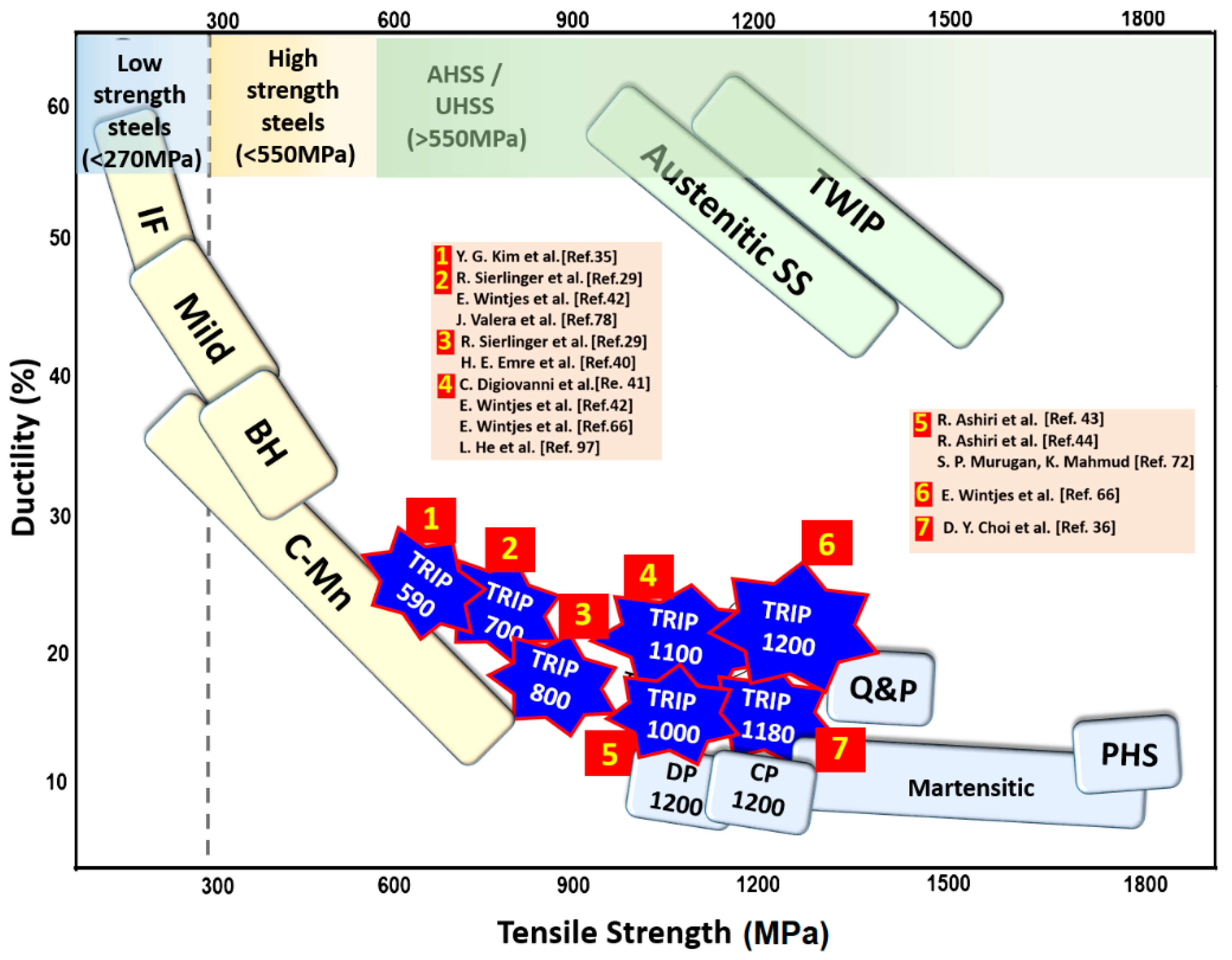
1.1. High Strength Steels: Trends and Definitions
1.1.1. Dual-Phase Steel
1.1.2. Complex Phase Steels
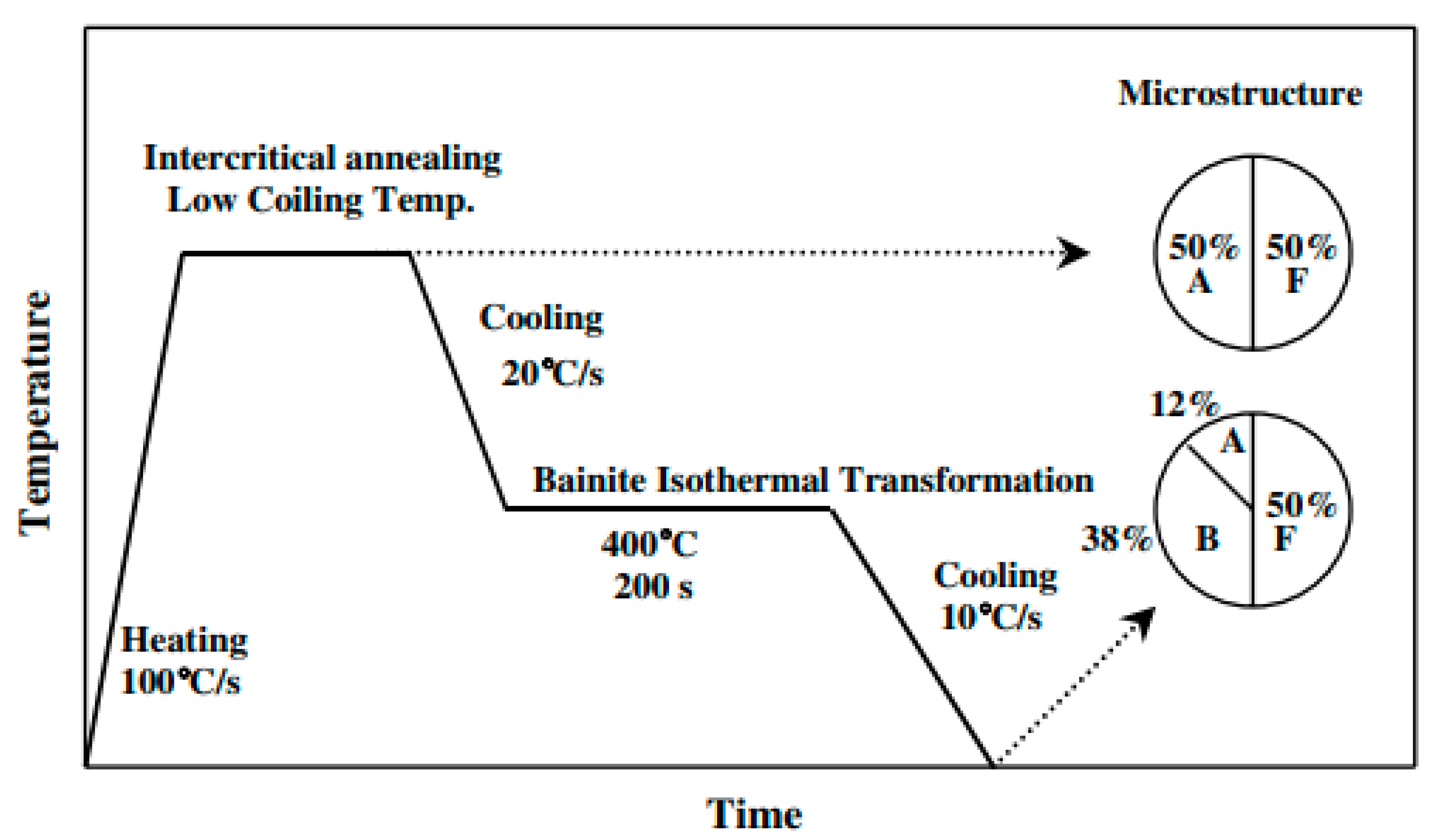
1.1.3. TRIP Steel
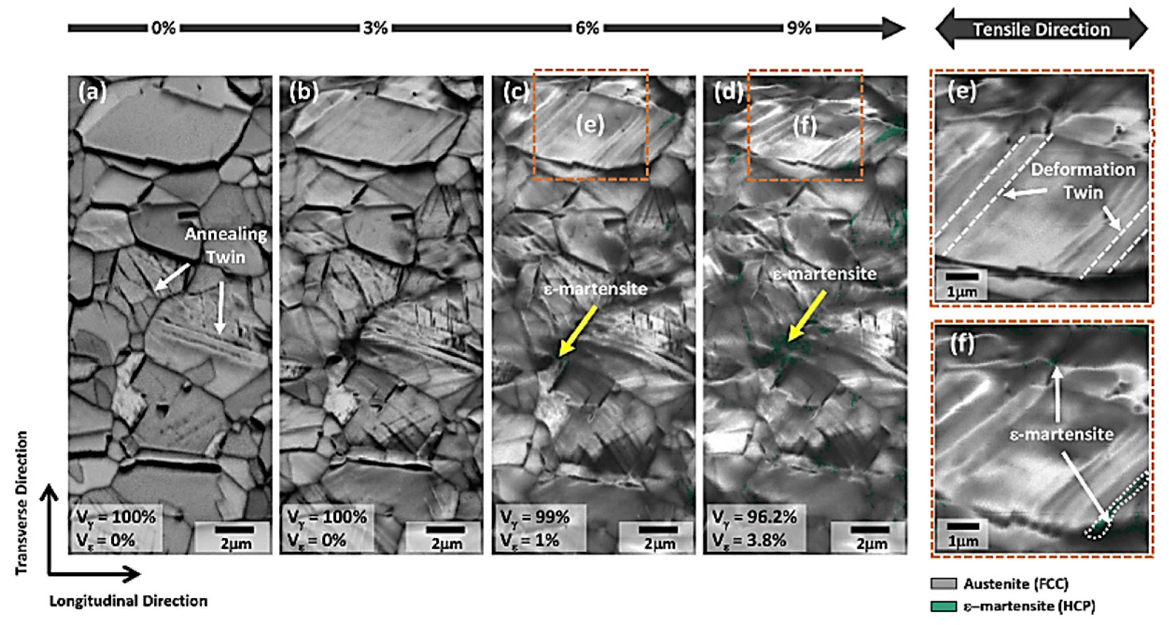
1.1.4. TWIP Steel
1.1.5. Martensitic Steel
1.2. The Necessity of Zn-Coated Steel
1.2.1. Galvanized Steel (GI)
1.2.2. Galvannealed Steel (GA)
1.2.3. Electro-galvanized Steel (EG)
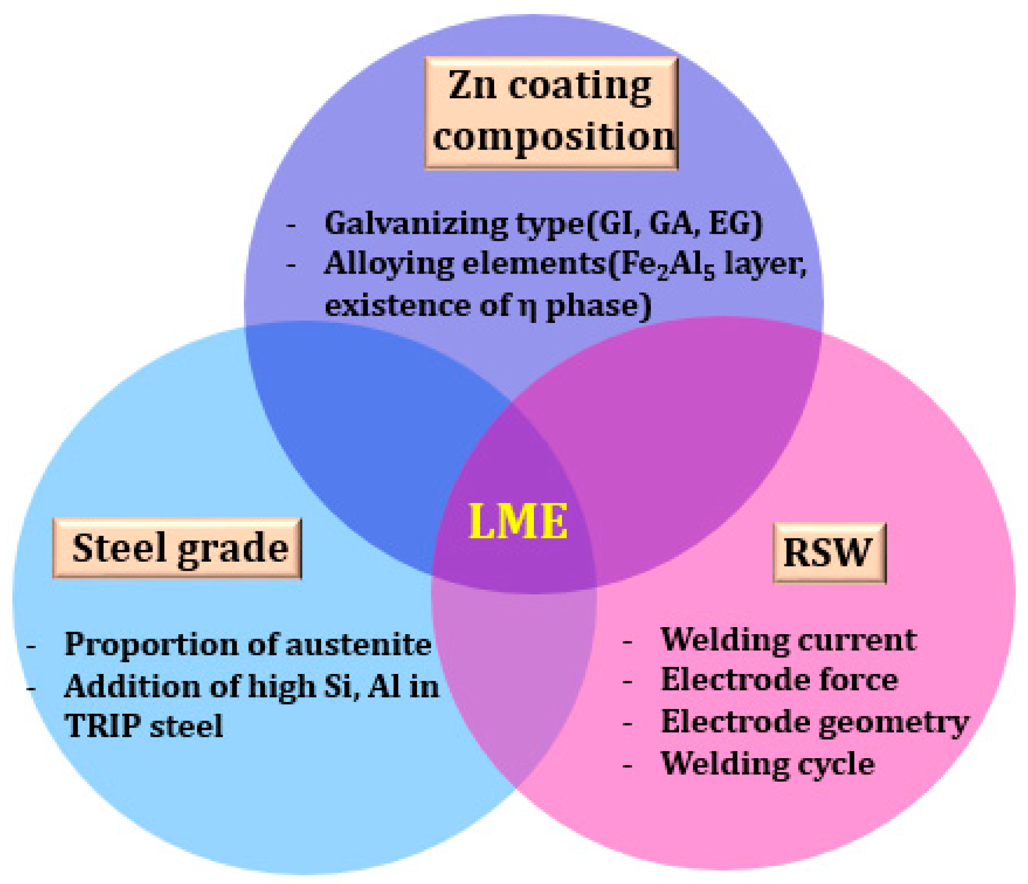
2. Liquid Metal Embrittlement (LME)
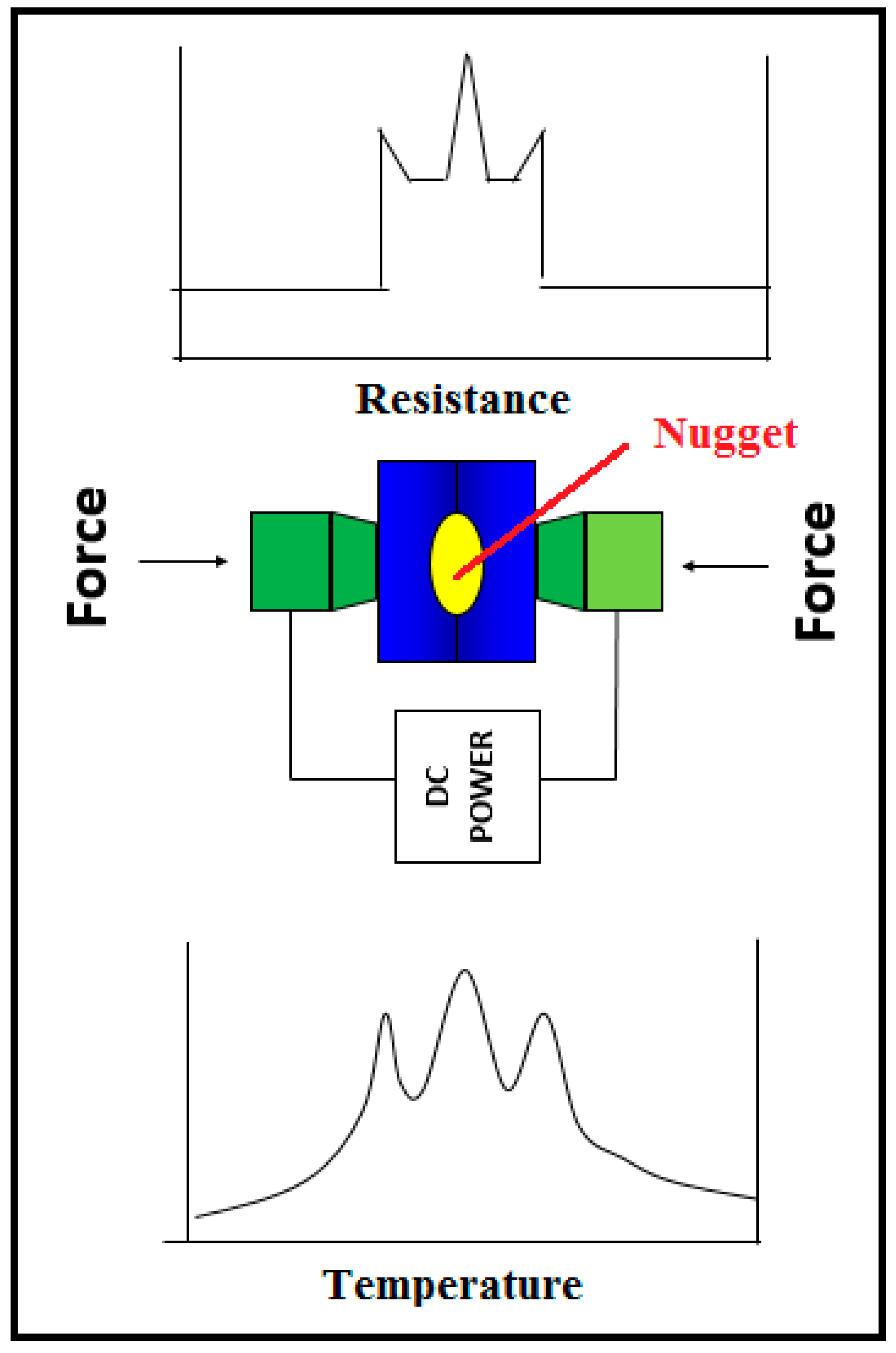
2.1. Resistance Spot Welding
2.2. LME Studies on Galvanized TRIP Steel
3. Galvanized TRIP Steel and LME Issues
3.1. TRIP Steel
3.2. Issues of Galvanized TRIP Steels
4. Resistance Spot Welding and LME Issues
4.1. Principle of Resistance Spot Welding and the Effect on LME
4.2. Parameters of Resistance Spot Welding on LME
5. Liquid Metal Embrittlement and its Suppression
5.1. Mechanisms of Zinc Penetration
5.2. Liquid Metal Embrittlement of TRIP Steel
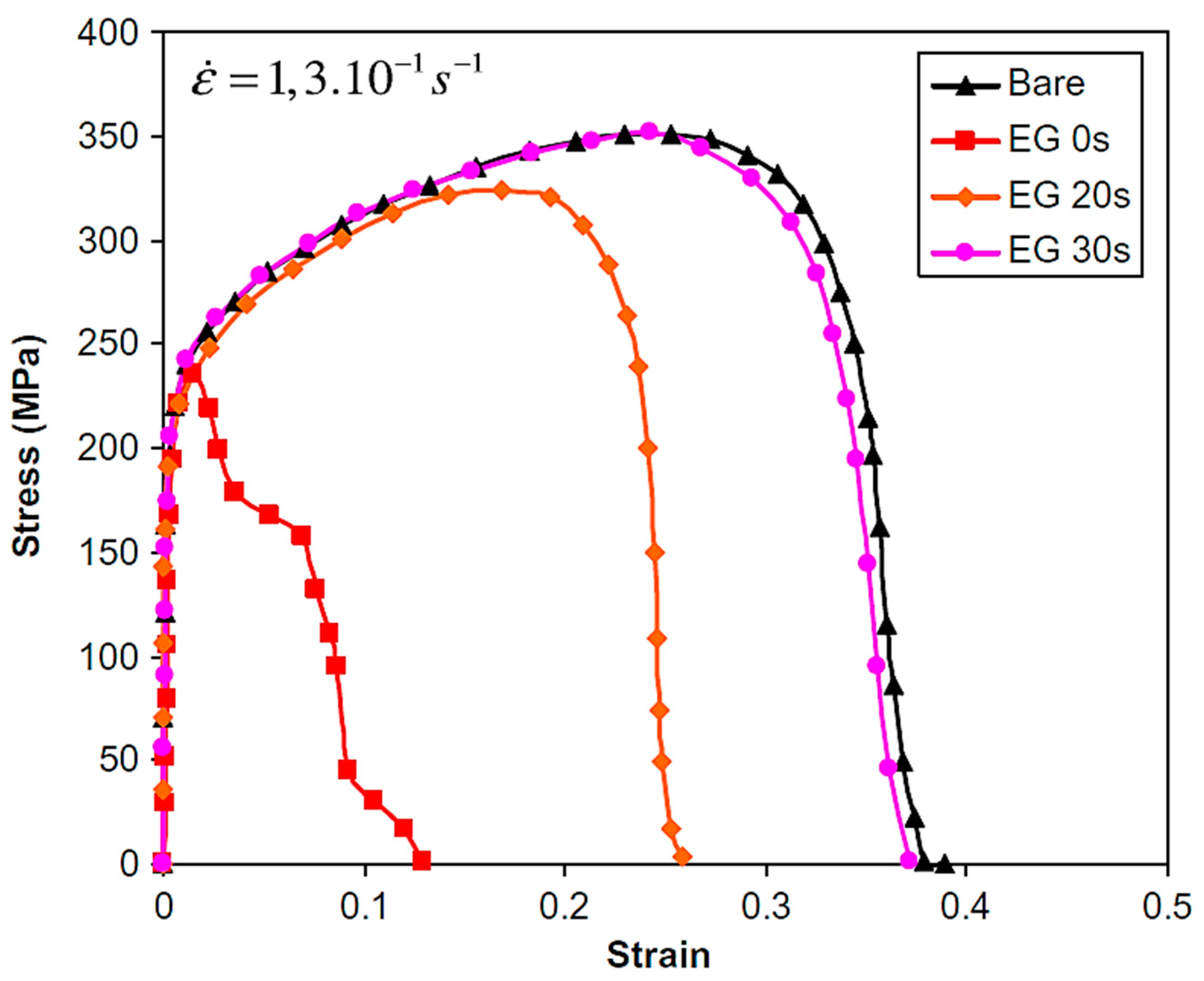
5.2.1. Influences to LME Sensitivity
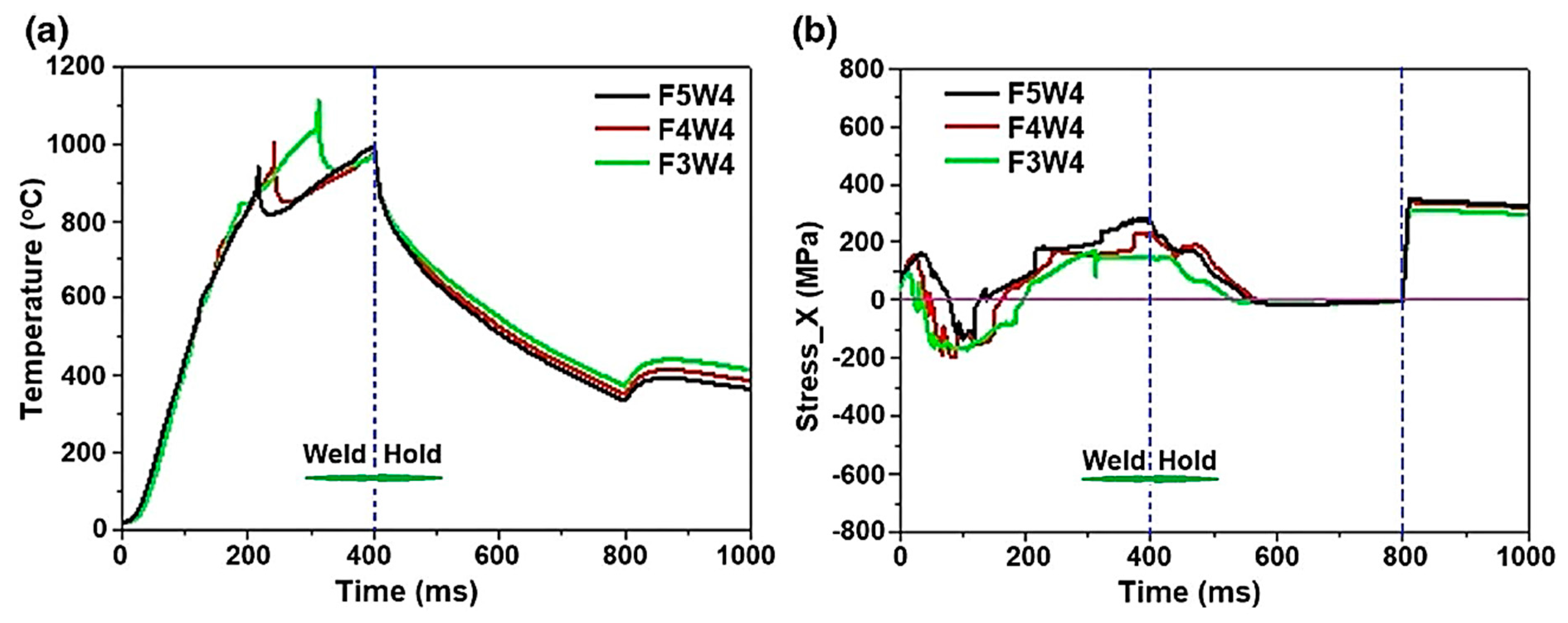
5.2.2. Effect of Electrode Force on LME
5.2.3. Effect of Electrode Geometry on LME Reduction
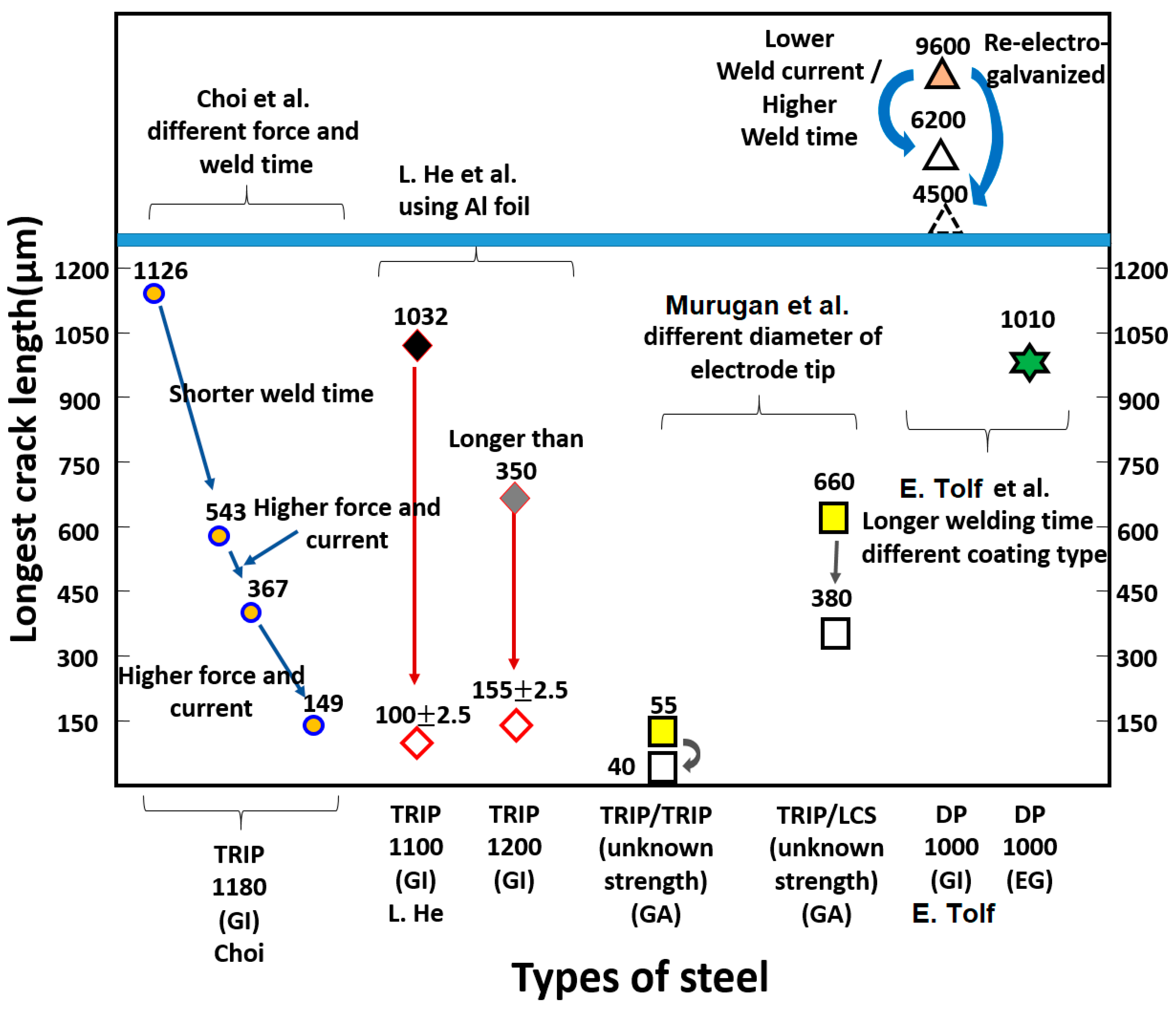
5.3. Evaluation of LME Crack on TRIP Steel
6. Future Guidelines and Prospects
7. Conclusions
Author Contributions
Funding
Conflicts of Interest
References
- Galan, J.; Samek, L.; Verleysen, P.; Verbeken, K.; Houbaert, Y. Advanced high strength steels for automotive industry. Rev. Metal. 2012, 48, 118–131. [Google Scholar] [CrossRef]
- Keeler, S.; Kimchi, M. Advanced High-Strength Steels Application Guidelines, Version 5.0; WorldAutoSteel: Brussels, Belgium, 2015. [Google Scholar]
- Han, T.K.; Lee, K.Y.; Kim, J.S. Recent developments and weldability of advanced high strength steels for automotive applications. JWJ 2009, 27, 13–18. [Google Scholar]
- April 2020 Crude Steel Production. Available online: https://www.worldsteel.org/media-centre/press-releases/2020/April-2020-crude-steel-production.html (accessed on 6 June 2020).
- Advanced High-strength Steel Market by Grade (Dual Phase, Transformation-Induced Plasticity, Complex Phase, and Others) and End User (Automotive, Construction, and Others)—Global Opportunity Analysis and Industry Forecast, 2017–2023. Available online: https://www.alliedmarketresearch.com/advanced-high-strength-steel-market (accessed on 6 June 2020).
- Thomas, G.; Koo, J.Y. Structure and Properties of Dual Phase Steels. In AIME Symposium; Kott, R.A., Morris, J.W., Eds.; Metallurgical Society of AIME: Englewood, CO, USA, 1979; p. 183. [Google Scholar]
- Jiang, Z.; Guan, Z.; Lian, J. Effects of microstructural variables on the deformation behaviour of dual-phase steel. Mater. Sci. Eng. A 1995, 190, 55–64. [Google Scholar] [CrossRef]
- Bag, A.; Ray, K.K.; Dwarakadasa, E.S. Influence of martensite content and morphology of tensile and impact properties of high-martensite dual-phase steels. Metall. Mater. Trans. A 1990, 30, 1193–1202. [Google Scholar] [CrossRef]
- Meng, Q.; Li, J.; Wang, J.; Zhang, Z.; Zhang, L. Effect of water quenching process on microstructure and tensile properties of low alloy cold rolled dual-phase steel. Mater Des. 2009, 30, 2379–2385. [Google Scholar] [CrossRef]
- Srivastava, A.K.; Patel, N.K.; Kumar, B.R.; Sharma, A.; Ahn, B. Strength–ductility trade-off in dual-phase steel tailored via controlled phase transformation. J. Mater. Eng. Perform. 2020, in press. [Google Scholar] [CrossRef]
- Fonstein, N. Advanced High Strength Sheet Steels, 1st ed.; Springer: Cham, Switzerland, 2015. [Google Scholar]
- Jeanneau, M.; Pichant, P. The trends of steel products in the European automotive industry. Rev. Métallurgie 2000, 97, 1399–1408. [Google Scholar] [CrossRef]
- Matsumura, O.; Sakuma, Y.; Takechi, H. Enhancement of elongation by retained austenite in intercritical annealed 0.4C-1.5Si-O.8Mn Steel. Scr. Metall. 1987, 21, 301–1306. [Google Scholar]
- Matsumura, O.; Sakuma, Y.; Takechi, H. Mechanical properties and retained Austenite in intercritically heat treated bainite-transformed steel and their variations with Si and Mn additions. Metall. Trans. A 1991, 22A, 489–498. [Google Scholar]
- Cooman, B.C.D. Structure-properties relationship in TRIP steels containing carbide-free bainite. Curr. Opin. Solid St. Mater. Sci. 2004, 8, 285–303. [Google Scholar] [CrossRef]
- Cooman, B.C.D.; Kwon, O.; Chin, K.G. State-of-the-knowledge on TWIP steel. Mater. Sci. Technol. 2012, 28, 513–527. [Google Scholar] [CrossRef]
- Horvath, C.D. Materials, Design and Manufacturing for Lightweight Vehicles. In Woodhead Publishing Series in Composites Science and Engineering; Mallick, P.K., Ed.; Woodhead Publishing: Cambridge, UK, 2010; pp. 35–78. [Google Scholar]
- Chung, P.P.; Wang, J.; Durandet, Y. Deposition processes and properties of coatings on steel fasteners—A review. Friction 2019, 7, 389–416. [Google Scholar] [CrossRef]
- Townsend, H.E.; Allegra, L.; Dutton, R.J.; Kriner, S.A. Hot-dip coated sheet steels-a review. Mater. Perform. 1986, 25, 36–46. [Google Scholar]
- Dionne, S. The characterization of continuous hot-dip galvanized and galvannealed steels. JOM 2006, 58, 32–40. [Google Scholar] [CrossRef]
- Shome, M.; Tumuluru, M. Welding and Joining of Advanced High Strength Steels (AHSS); Woodhead Publication Series in Welding and Other Joining Series 85; Woodhead Publishing: Cambridge, UK, 2015. [Google Scholar]
- Lynch, S.P. Stress Corrosion Cracking. In Woodhead Publishing Series in Metals and Surface Engineering; Raja, V.S., Shoji, T., Eds.; Woodhead Publishing: Cambridge, UK, 2011. [Google Scholar]
- Ashiri, R.; Shamanian, M.; Salimijazi, H.R.; Haque, M.A.; Bae, J.H.; Ji, C.W.; Chin, K.G.; Park, Y.D. Liquid metal embrittlement-free welds of Zn-coated twinning induced plasticity steels. Scr. Mater. 2016, 114, 41–47. [Google Scholar] [CrossRef]
- Yi, H.L.; Lee, K.Y.; Kim, J.H.; Bhadesia, H.K.D.H. Spot weldability of δ-TRIP steel containing 0·4 wt-%C. Sci. Technol. Weld. Join. 2010, 15, 619. [Google Scholar] [CrossRef]
- Murugan, S.P.; Cheepu, M.; Vijayan, V.; Ji, C.; Park, Y.D. The resistance spot weldability of a stainless steel/aluminium/low carbon steel 3-ply clad sheet. JWJ 2018, 36, 25–33. [Google Scholar] [CrossRef]
- Kim, D.C.; Jo, H.G.; Kim, Y.M.; Kang, M.J.; Hwang, I. Effects of electrode face thickness on resistance spot weldability of aluminium alloy 6061. JWJ 2020, 38, 67–72. [Google Scholar] [CrossRef]
- Lee, J.J.; Son, C.S.; Park, Y.W. Resistance spot welding characteristic of 1500MPa steel sheet using simulation (II)—Estimation model for nugget diameter of resistance spot welds. JWJ 2018, 36, 51–56. [Google Scholar] [CrossRef]
- Choi, S.G.; Hwang, I.; Kang, M.; Hyun, S.; Kim, Y.M. Optimization of welding parameters in resistance spot welding of 980 MPa grade GA steel sheet using multi-response surface methodology. JWJ 2018, 36, 63–69. [Google Scholar] [CrossRef]
- Sierlinger, R.; Gruber, M. A Cracking Good Story about Liquid Metal Embrittlement During Spot Welding of Advanced High Strength Steels; White Paper; Voestalpine Stahl GmbH, Voestalpine-Strabe: Linz, Austria, 2016; pp. 1–16. [Google Scholar]
- Li, Y.; Ma, Y.; Lou, M.; Lei, H.; Lin, Z. Advances in Welding and Joining Processes of Multi-material Lightweight Car Body. J. Mech. Eng. 2016, 52, 1–23. (In Chinese) [Google Scholar] [CrossRef]
- Cho, G. The Automotive Industry: Core Research from Industry; Abington Publishing, Woodhead Publishing Limited: Cambridge, UK, 2000. [Google Scholar]
- Klinger, J.F. Automotive Body Structure Assembly, Mass and Cost Saving Potential of Laser Welding Compared to Spot Welding. Master’s Thesis, KTH Royal Institute of Technology, Stockholm, Sweden, 2012. [Google Scholar]
- Bhattacharya, D. Liquid metal embrittlement during resistance spot welding of Zn-coated high-strength steels. Mater. Sci. Technol. 2018, 34, 1809–1829. [Google Scholar] [CrossRef]
- Kim, S.J.; Jeong, H. Development of structural steel and trend of welding technology. JWJ 2016, 34, 7–20. [Google Scholar]
- Kim, Y.G.; Kim, I.J.; Kim, J.S.; Chung, Y.I.; Choi, D.Y. Evaluation of Surface Crack in Resistance Spot Welds of Zn-Coated Steel. Mater. Trans. 2014, 55, 171–175. [Google Scholar] [CrossRef]
- Choi, D.Y.; Sharma, A.; Uhm, S.H.; Jung, J.P. Liquid metal embrittlement of resistance spot welded 1180 TRIP steel: Effect of electrode force on cracking behavior. Met. Mater. Int. 2018, 25, 219–228. [Google Scholar] [CrossRef]
- Zhou, K.; Cai, L. Study on effect of electrode force on resistance spot welding process. J. Appl. Phys. 2014, 116, 084902. [Google Scholar] [CrossRef]
- Jo, H.G.; Kim, Y.M.; Kang, M.J.; Kim, D.C. Effects of electrode face radius and force on resistance spot weldability of aluminium Alloy 6061. JWJ 2018, 36, 46–51. [Google Scholar] [CrossRef]
- Jo, B.J.; Kim, J.S.; Yoo, H.S.; Kim, I.J.; Lee, S.H.; Kim, Y.G. Characterization of resistance spot welded Al5052/DP590 dissimilar materials and processing optimization. JWJ 2015, 33, 56–61. [Google Scholar]
- Emre, H.E.; Kacar, R. Resistance spot weldability of galvanize coated and uncoated TRIP steels. Metals 2016, 6, 299. [Google Scholar] [CrossRef]
- Digiovanni, C.; Han, X.; Powell, A.; Biro, E.; Zhou, N.Y. Experimental and numerical analysis of liquid metal embrittlement crack location. J. Mater. Eng. Perform. 2019, 28, 2045–2052. [Google Scholar] [CrossRef]
- Wintjes, E.; Digiovanni, C.; He, L.; Biro, E.; Zhou, Y.N. Quantifying the link between crack distribution and resistance spot weld strength reduction in liquid metal embrittlement susceptible steels. Weld. World 2019, 63, 807–814. [Google Scholar] [CrossRef]
- Ashiri, R.; Marashi, S.P.H.; Park, Y.D. Weld processing and mechanical responses of 1-GPa TRIP steel resistance spot welds. Weld. J. 2018, 97, 157–169. [Google Scholar]
- Ashiri, R.; Mostaan, H.; Park, Y.D. A phenomenological study of weld discontinuities and defects in resistance spot welding of advanced high strength TRIP steel. Metall. Mater. Trans. A 2018, 49, 6161–6172. [Google Scholar] [CrossRef]
- Kim, Y.H.; Kim, Y.G.; Kim, D.C.; Joo, S.M. Optimization of weld-bonding process conditions of dissimilar materials using delta spot welding. JWJ 2019, 37, 231–236. [Google Scholar] [CrossRef]
- Béres, G.; Tisza, M. Vehicle and Automotive Engineering. In Lecture Notes in Mechanical Engineering; Jármai, K., Bolló, B., Eds.; Springer: Cham, Switzerland, 2017; p. 204. [Google Scholar]
- Choi, J.H.; Jo, M.C.; Lee, H.S.; Zargaran, A.; Song, T.; Sohn, S.S.; Kim, N.J.; Lee, S. Cu addition effects on TRIP to TWIP transition and tensile property improvement of ultra-high-strength austenitic high-Mn steels. Acta Mater. 2019, 166, 246–260. [Google Scholar] [CrossRef]
- Papatriantafillou, I.; Agoras, M.; Aravas, N.; Haidemenopoulos, G.N. Constitutive modeling and finite element methods for TRIP steels. Comput. Methods Appl. Mech. Eng. 2006, 195, 5094–5114. [Google Scholar] [CrossRef]
- Maki, J.; Mahieu, J.; Cooman, B.C.D.; Claessens, S. Galvanisability of silicon free CMnAl TRIP steels. Mater. Sci. Technol. 2003, 19, 125–131. [Google Scholar] [CrossRef]
- Wang, X.D.; Huang, B.X.; Rong, Y.H.; Wang, L. Microstructures and stability of retained austenite in TRIP steels. Mater. Sci. Eng. A 2006, 438–440, 300–305. [Google Scholar] [CrossRef]
- Hao, Q.; Qin, S.; Liu, Y.; Zuo, X.; Chen, N.; Huang, W.; Rong, Y. Effect of retained austenite on the dynamic tensile behavior of a novel quenching-partitioning-tempering martensitic steel. Mater. Sci. Eng. A 2016, 662, 16–25. [Google Scholar] [CrossRef]
- Park, S.S.; Choi, Y.M.; Nam, D.G.; Kim, Y.S.; Yu, J.H.; Park, Y.D. Evaluation of resistance spot weld interfacial fractures in tensile-shear tests of TRIP 1180 steels. JWJ 2009, 26, 81–91. [Google Scholar]
- Lee, J.D.; Lee, S.J.; Bang, J.H.; Yoon, G.S.; Kim, M.S.; Kim, J.K. Weld quality evaluation method for the resistance spot welds using X-ray transmission inspection. JWJ 2014, 32, 537–543. [Google Scholar]
- Herrera, C.; Ponge, D.; Raabe, D. Design of a novel Mn-based 1 GPa duplex stainless TRIP steel with 60% ductility by a reduction of austenite stability. Acta Mater. 2011, 59, 4653–4664. [Google Scholar] [CrossRef]
- Blumenau, M.; Norden, M.; Friedel, F.; Peters, K. Galvannealing of (high-) manganese-alloyed TRIP- and X-IP®-steel. Steel Res. Int. 2010, 81, 1125–1136. [Google Scholar] [CrossRef]
- Meyer, M.D.; Wit, K.D.; Cooman, B.D. The bake hardening behavior of electro-galvanized cold rolled CMnSi and CMnAlSi TRIP steel. Steel Res. 2000, 71, 511–518. [Google Scholar] [CrossRef]
- Bellhouse, E.M.; Mertens, A.I.M.; McDermid, J.R. Development of the surface structure of TRIP steels prior to hot-dip galvanizing. Mater. Sci. Eng. A 2007, 463, 147–156. [Google Scholar] [CrossRef]
- Jacques, P.J.; Girault, E.; Mertens, A.; Verlinden, B.; Humbeeck, J.V.; Delannay, F. The developments of cold-rolled TRIP-assisted multiphase steels. Al-alloyed TRIP-assisted multiphase steels. ISIJ Int. 2001, 41, 1068–1074. [Google Scholar] [CrossRef]
- Mahieu, J.; Cooman, B.C.D.; Claessens, S. Galvanizability of high-strength steels for automotive applications. Metall. Mater. Trans. A 2001, 32, 2905–2908. [Google Scholar] [CrossRef]
- Bellhouse, E.M.; Mcdermid, J.R. Selective oxidation and reactive wetting during hot-dip galvanizing of a 1.0% Al–0.5% Si TRIP-assisted steel. Metall. Mater. Trans. A 2012, 43, 2426–2441. [Google Scholar] [CrossRef]
- Oh, J.H.; Cho, L.; Kim, M.; Kang, K.; Cooman, B.C.D. The effect of Bi on the selective oxide formation on CMnSi TRIP steel. Metall. Mater. Trans. A 2016, 47, 5474–5486. [Google Scholar] [CrossRef]
- Wang, K.K.; Hsu, C.W.; Chang, L.; Gan, D.; Yang, K.C. Role of Al in Zn bath on the formation of the inhibition layer during hot-dip galvanizing for a 1.2Si–1.5Mn transformation-induced plasticity steel. Appl. Surf. Sci. 2013, 285, 458–468. [Google Scholar] [CrossRef]
- Cho, L.; Kim, M.S.; Kim, Y.H.; Cooman, B.C.D. Influence of gas atmosphere dew point on the galvannealing of CMnSi TRIP steel. Metall. Mater. Trans. A 2013, 44, 5081–5095. [Google Scholar] [CrossRef]
- Son, J.W.; Nam, D.G.; Kim, D.C.; Park, Y.D. Effect of paint baking on the strength and failure of spot welds for 780 TRIP steels. JWJ 2010, 28, 66–73. [Google Scholar] [CrossRef][Green Version]
- Oikawa, H.; Murayama, G.; Hiwatashi, S.; Matsuyama, K. Resistance spot weldability of high strength steel sheets for automobiles and the quality assurance of joints. Weld. World 2007, 51, 7–18. [Google Scholar] [CrossRef]
- Wintjes, E.; Digiovanni, C.; He, L.; Bag, S.; Goodwin, F.; Biro, E.; Zhou, Y. Effect of multiple pulse resistance spot welding schedules on liquid metal embrittlement severity. J. Manuf. Sci. Eng. 2010, 141, 101001. [Google Scholar] [CrossRef]
- Galler, M.; Enzinger, N.; Sommitsch, C. The estimation of the contact interface temperature during resistance spot welding of zinc coated steels using numerical technique. Mater. Sci. Eng. Technol. 2010, 41, 925–930. [Google Scholar]
- Huda, N.; Nam, D.G.; Park, Y.D. Study on the mechanism of nugget growth behavior in three sheets stack resistance spot welding. JWJ 2019, 37, 564–571. [Google Scholar] [CrossRef]
- Wu, K.C. Resistance spot welding of high contact-resistance surfaces for weldbonding. Welding J. Res. Suppl. 1975, 54, 436s–443s. [Google Scholar]
- Tolf, E.; Hedegard, J.; Melander, A. Surface breaking cracks in resistance spot welds of dual phase steels with electrogalvanised and hot dip zinc coating. Sci. Technol. Weld. Join. 2013, 18, 25–31. [Google Scholar] [CrossRef]
- Digiovanni, C.; Bag, S.; Mehling, C.; Choi, K.W.; Macwan, A.; Biro, E.; Zhou, Y.N. Reduction in liquid metal embrittlement cracking using weld current ramping. Weld. World 2019, 63, 1583–1591. [Google Scholar] [CrossRef]
- Murugan, S.P.; Mahmud, K.; Ji, C.; Jo, I.; Park, Y.D. Critical design parameters of the electrode for liquid metal embrittlement cracking in resistance spot welding. Weld. World 2019, 63, 1613–1632. [Google Scholar] [CrossRef]
- Barthelmie, J.; Schram, A.; Wesling, V. Liquid metal embrittlement in resistance spot welding and hot tensile tests of surface-refined TWIP steels. IOP Conf.: Mater. Sci. Eng. 2016, 118, 012002. [Google Scholar] [CrossRef]
- Ashiri, R.; Haque, M.A.; Ji, C.W.; Shamanian, M.; Salimijazi, H.R.; Park, Y.D. Supercritical area and critical nugget diameter for liquid metal embrittlement of Zn-coated twining induced plasticity steels. Scr. Mater. 2015, 109, 6–10. [Google Scholar] [CrossRef]
- Digiovanni, C.; He, L.; Pistek, U.; Goodwin, F.; Biro, E.; Zhou, Y.N. Role of spot weld electrode geometry on liquid metal embrittlement crack development. J. Manuf. Proc. 2020, 49, 1–9. [Google Scholar] [CrossRef]
- Lee, K.J.; Kim, S.H.; Kwon, E.P.; Son, K.S. Friction stir welding of 900MPa grade TWIP steel. JWJ 2014, 32, 135–139. [Google Scholar]
- Hwang, S.; Yoon, H.S.; Kim, D.C.; Kang, M.J.; Kim, J.D.; Kim, Y.M. Resistance spot weldability of low density lightweight steel according to electrode shape. JWJ 2017, 35, 52–57. [Google Scholar] [CrossRef]
- Valera, J.; Miguel, V.; Martinez, A.; Naranjo, J.; Canas, M. Optimization of electrical parameters in resistance rpot welding of dissimilar joints of micro-alloyed steels TRIP sheets. Procedia Manuf. 2017, 13, 291. [Google Scholar] [CrossRef]
- Stoloff, N.S.; Johnston, T.L. Crack propagation in a liquid metal environment. Acta Metall. 1963, 11, 251–256. [Google Scholar] [CrossRef]
- Glickman, E.E. Dissolution condensation mechanism of stress corrosion cracking in liquid metals: Driving force and crack kinetics. Metall. Mater. Trans. A 2011, 42, 250–266. [Google Scholar] [CrossRef]
- Lynch, S.P. Environmentally assisted cracking: Overview of evidence for an adsorption-induced localised-slip process. Acta Metall. 1988, 36, 2639–2661. [Google Scholar] [CrossRef]
- Dmukhovskays, G.; Popovich, V.V. A phenomenological model of embrittlement of metals under conditions of the adsorption action of liquid metal media. Sov. Mater. Sci. 1983, 18, 461–467. [Google Scholar] [CrossRef]
- Nicholas, M.G.; Old, C.F. Liquid metal embrittlement. J. Mater. Sci. 1979, 14, 1–18. [Google Scholar] [CrossRef]
- Gordon, P.; An, H.H. The mechanisms of crack initiation and crack propagation in metal-induced embrittlement of metals. Metall. Trans. 1982, 13, 457–472. [Google Scholar] [CrossRef]
- Klinger, L.; Rabkin, E. Theory of the Kirkendall effect during grain boundary interdiffusion. Acta Mater. 2011, 59, 1389–1399. [Google Scholar] [CrossRef]
- Shunk, F.A.; Warke, W.R. Specificity as an aspect of liquid metal embrittlement. Scr. Metall. 1974, 8, 519–526. [Google Scholar] [CrossRef]
- Ling, Z.; Wang, M.; Kong, L. Liquid Metal Embrittlement of Galvanized Steels During Industrial Processing: A Review. In Transactions on Intelligent Welding Manufacturing; Chen, S., Zhang, Y., Feng, Z., Eds.; Springer: Singapore, 2018; p. 29. [Google Scholar]
- Frappier, R.; Paillard, P.; Gall, R.L.; Dupuy, T. Embrittlement of steels by liquid zinc: Crack propagation after grain boundary wetting. Adv. Mater. Res. 2014, 922, 161–166. [Google Scholar] [CrossRef]
- Glickman, E.E. grain boundary grooving accelerated by local plasticity as a possible mechanism of liquid metal embrittlement. Interf. Sci. 2003, 11, 451–459. [Google Scholar] [CrossRef]
- Joseph, B.; Picat, M.; Barbier, F. Liquid metal embrittlement: A state-of-the-art appraisal. Eur. Phys. J. Appl. Phys. 1999, 5, 19–31. [Google Scholar] [CrossRef]
- Ratanaphan, S.; Sarochawikasit, R.; Kumanuvong, N.; Hayakawa, S.; Beladi, H.; Rohrer, G.S.; Okita, T. Atomistic simulations of grain boundary energies in austenitic steel. J. Mater. Sci. 2019, 54, 5570–5583. [Google Scholar] [CrossRef]
- Wang, J.; Madsen, G.K.H.; Drautz, R. Grain boundaries in bcc-Fe: A density-functional theory and tight-binding study. Model. Simul. Mater Sci. Eng. 2018, 26, 025008. [Google Scholar] [CrossRef]
- Yu, J.; Yun, S.; Rhee, S. Optimization of fuzzy controller for constant current of inverter DC resistance spot welding using genetic algorithm. JWJ 2010, 28, 99–105. [Google Scholar]
- Kim, J.K.; Woo, I.S.; Jeong, B.; Lee, J.B. Resistance spot weldability of ferritic stainless steel and galvanized steel. JWJ 2007, 24, 39–43. [Google Scholar]
- Popovich, V.V. Mechanisms of liquid-metal embrittlement. Fiz.-Khim. Mekh. Mater. 1979, 15, 11–20. [Google Scholar] [CrossRef]
- Beal, C.; Kleber, X.; Fabregue, D.; Mohamed, B. Liquid zinc embrittlement of twinning-induced plasticity steel. Scr. Mater 2012, 66, 1030–1033. [Google Scholar] [CrossRef]
- He, L.; Digiovanni, C.; Han, X.; Mehling, C.; Wintjes, E.; Biro, E.; Zhou, N.Y. Suppression of liquid metal embrittlement in resistance spot welding of TRIP steel. Sci. Technol. Weld. Join. 2019, 24, 579–586. [Google Scholar] [CrossRef]
- Marder, A.R. The metallurgy of zinc-coated steel. Prog. Mater. Sci. 2000, 45, 191–271. [Google Scholar] [CrossRef]
- Kim, S.H.; Lee, J.H. Analysis of residual stresses for the multipass welds of 316L stainless steel pipe by neutron diffraction method. JWJ 2003, 21, 64–70. [Google Scholar]
- Kang, H.S.; Cho, L.; Lee, C.; Cooman, B.C.D. Zn penetration in liquid metal embrittled TWIP Steel. Metall. Mater. Trans. A 2016, 47, 2885–2905. [Google Scholar] [CrossRef]
- DiGiovanni, C.; Biro, F.; Zhou, N.Y. Impact of liquid metal embrittlement cracks on resistance spot weld static strength. Sci. Technol. Weld. Join. 2019, 24, 218–224. [Google Scholar] [CrossRef]
- Gaul, H.; Weber, G.; Rethmeier, M. Influence of HAZ cracks on fatigue resistance of resistance spot welded joints made of advanced high strength steels. Sci. Technol. Weld. Join. 2011, 16, 440–445. [Google Scholar] [CrossRef]
- Lee, H.S.; Jo, M.C.; Sohn, S.S.; Kim, S.H.; Song, T.; Kim, S.K.; Kim, H.S.; Kim, N.J.; Lee, S. Microstructural evolution of liquid metal embrittlement in resistance-spot-welded galvanized TWinning-Induced Plasticity (TWIP) steel sheets. Mater. Charact. 2019, 147, 233–241. [Google Scholar] [CrossRef]
- Sharma, A.; Roh, M.H.; Jung, D.H.; Jung, J.P. Effect of ZrO2 nanoparticles on the microstructure of Al-Si-Cu filler for low-temperature Al brazing applications. Metall. Mater. Trans. A 2016, 47, 510–521. [Google Scholar] [CrossRef]
- Sharma, A.; Lim, D.U.; Jung, J.P. Microstructure and brazeability of SiC nanoparticles reinforced Al–9Si–20Cu produced by induction melting. Mater. Sci. Technol. 2016, 32, 773–779. [Google Scholar] [CrossRef]


| Steel Type | Coating | Welding parameters | Properties |
|---|---|---|---|
| TRIP 590 [36] | HDGA | 8 mm diameter dome/flat type Cu–Cr electrode; 4–6 kN force, 10.5–12.0 kA weld current. | 1. Surface crack decreased with increasing force/holding time and decreasing weld current/weld time. 2. Slight decrease in cracks for flat type rather than dome shape electrode. |
| TRIP 700/800 (Al-Si) [29] | HDGI/EG | Cu–Cr–Zr electrode. | 1. GI TRIP 700 and EG TRIP 800 showed LME cracks. 2. Crack propagation decreased by increasing the heat input. |
| TRIP 800 (0.2C-1.69Mn-1.66Si-0.43Al) [40] | HDGI | 5.5 mm diameter spherical Cu–Cr–Zr electrode; 6 kN force, 6–9 kA weld current. | 1. Larger heat-affected zone (HAZ) was observed because of the high thermal conductivity of the coating. 2. Tensile shear strength was improved by increasing welding current and welding time. |
| TRIP 1180 (0.17C-2.6Mn-1.5Si) [36] | HDGI | 5.5 mm diameter dome type(ISO 5821, type B0) Cu–Cr–Zr; 3–5 kN force, 6–7.5 kA weld current. | 1. LME crack size was increased as electrode force decreases. 2. LME cracks propagated further at longer holding time. |
| TRIP 1100 (0.2C-2.17Mn-1.61Si) [41] | HDGI | 7 mm modified dome-shaped electrode tip(end of the tip was polished at 1 degree); 5.5 kN force, 11 kA weld current. | 1. Lap shear strength was measured on the varying location of cracks. 2. With the varying location of cracks, lap shear strength increased from 7.8 to 42.2% compared to bare steel. |
| TRIP 690 (0.2C-1.7Mn-0.4Si-1.31Al) TRIP 1100 (0.2C-2.2Mn-1.6Si) TRIP 1200 (0.22C-2.3Mn-1.7Si) [42] | HDGI | 6–7 mm diameter electrode, female B-type electrode caps; 3.6–5.5 kN force, 10–10.5 kA weld current. | 1. Tensile lap shear strength decreased for the welds in TRIP. 2. Multiplying lognormal median crack length by the number of cracks per weld was suggested to explain the critical crack location. |
| TRIP 1000 (0.26C-2.18Mn-1.09Si-0.52Al) [43] | HDGA | 6 mm diameter dome-radius type Cu–Cr electrode tip; 4 kN force, 4–10 kA weld current. | 1. Higher nugget penetration depth resulted in higher tensile shear strength and cross tensile strength. |
| TRIP 1000 (C-Mn-Si-Al) [44] | HDGA | 6 mm diameter dome-radius type Cu–Cr– Zr electrode tip; 4 kN force, 4–10 kA weld current. | 2. Weld discontinuities and defects are created. 3. With higher than critical welding current, tensile strength (CTS) and tensile shear strength (TSS) are degraded. |
| Galvanizing | Steel Type | Galvanizing Property |
|---|---|---|
| HDGI | CMnSi TRIP steel (0.19C-1.57Mn-1.46Si) [60] | 1. Zn-0.2Al, 460 °C bath. 2. Island-like features at the grain boundary of ferrite and austenite resulting from high solubility of Si in ferrite. |
| HDGI | 0.2C-1.52Mn-0.45Si-1.0Al TRIP steel [49] | 1. Zn-0.2Al, 460 °C bath. 2. At −53, −30 °C dew point, the aluminothermic reduction occurred to form Fe2Al5-xZnx layer while at +5 °C dew point a bare area was noticed after dipping. |
| HDGI | CMnAl TRIP steel (0.18C-1.56Mn-1.73Al) [61] | 1. Zn-0.2Al, 460 °C bath. 2. Dew points were +10, −30, −50 °C. Al substituted the Si and oxidized internally during hot-rolling, showed limited Al contents at surface. |
| HDGI | CMnSi-Bi TRIP steel (0.08C-1.64Mn-1.48Si-0.04–0.19Bi) [62] | 1. Zn-0.22Al, 460 °C bath. 2. The addition of Bi could control the surface oxidation. The thickness of Mn-enriched oxide layer decreased with addition of Bi. |
| HDGA | TRIP steel (0.1C-1.49Mn-1.22Si-0.04Al) [55] | 1. Zn-0.14–0.18Al, 460 °C bath. 2. It was concluded that MnSiO3 and Mn2SiO4 were reduced by Al to form voids. Then Fe surface was dissolved to form Fe2Al5 layer. |
| HDGA | Mn-Al TRIP steel (1.7Mn-1.5Al), high Mn alloyed steel (23Mn) [63] | 1. Zn-0.14Al-0.035Fe, 460 °C bath, 2. Galvannealed at 500–600 °C for 15 s. Compared to low alloy steel, galvannealing kinetics become slower at high Mn alloyed steel. |
| HDGA | CMnSi TRIP steel (2.2Mn-1.4Si) [64] | 1. Zn-0.13Al, 460 °C bath, 2. Galvannealed at 540 to 570 °C. δ(FeZn10) and η(Zn) layer were found at −60, −30 °C dew point atm annealed steel, while δ and Г(Fe3Zn10), Г1(Fe11Zn40) layer were found at each −10, 0, 5 °C dew point annealed one. |
| EG | CMnSi (0.19C-1.57Mn-1.46Si), CMnAlSi (0.31C-1.57Mn-0.34Si-1.23Al) TRIP steel [65] | 1. Hydrogen atoms are absorbed to the TRIP steel surface because of high H solubility in austenite during electro-galvanizing, resulting in H embrittlement. |
© 2020 by the authors. Licensee MDPI, Basel, Switzerland. This article is an open access article distributed under the terms and conditions of the Creative Commons Attribution (CC BY) license (http://creativecommons.org/licenses/by/4.0/).
Share and Cite
Jeon, W.-S.; Sharma, A.; Jung, J.P. Liquid Metal Embrittlement of Galvanized TRIP Steels in Resistance Spot Welding. Metals 2020, 10, 787. https://doi.org/10.3390/met10060787
Jeon W-S, Sharma A, Jung JP. Liquid Metal Embrittlement of Galvanized TRIP Steels in Resistance Spot Welding. Metals. 2020; 10(6):787. https://doi.org/10.3390/met10060787
Chicago/Turabian StyleJeon, Wook-Sang, Ashutosh Sharma, and Jae Pil Jung. 2020. "Liquid Metal Embrittlement of Galvanized TRIP Steels in Resistance Spot Welding" Metals 10, no. 6: 787. https://doi.org/10.3390/met10060787
APA StyleJeon, W.-S., Sharma, A., & Jung, J. P. (2020). Liquid Metal Embrittlement of Galvanized TRIP Steels in Resistance Spot Welding. Metals, 10(6), 787. https://doi.org/10.3390/met10060787