Abstract
Welding is a widely used process that requires continuous developments to meet new application demands of mechanical projects under severe conditions. The homogeneity of metallurgical and mechanical properties in welded joints is the key factor for any welding process. The applications of external magnetic fields, mechanical vibration, and ultrasound are the fundamental steps to achieve success in improving these properties. The present work aimed at determining suitable processing conditions to achieve the desired balance between metallurgical and mechanical properties of 304L steel in TIG (Tungsten Inert Gas) welding under the application of an external magnetic field. The microstructural characteristics of the weld bead were analyzed by optical microscopy (OM) and scanning electron microscopy (SEM). In order to evaluate the mechanical properties of the welded specimen, its Vickers microhardness map and Charpy impact energy at −20 °C were obtained. In addition, corrosion tests were carried out in the saline medium to compare the corrosion resistance of the joint with that of the base metal and that without the magnetic field. It was found that the external magnetic field decreased the percentage of delta ferrite, improved the filling of the weld pool with the weld metal, and decreased the primary and secondary dendritic spacings. The Vickers microhardness value under the magnetic field was found to be lower than that without the magnetic field, and the Charpy test showed no significant variation in energy absorption. Moreover, the welded joint produced under the external magnetic field manifested less resistance to corrosion.
1. Introduction
In recent years, welding has attracted widespread attention in mechanical and construction projects owing to its several advantages, including high energy density, good geometry, and high efficiency [1,2,3,4,5]. However, the formation of spatters, pores, and bulging and other defects during welding degrade the quality of weld beads [3]. According to Baldan et al. [5], the main problems during welding are root dropout, overlap, lack of penetration, undercut, lack of fusion, and cracks. Different approaches, such as welding with mechanical agitation, ultrasound, and an external magnetic field, have been employed to minimize or avoid these problems.
Ultrasonic welding requires a high power to fill the fusion zone (FZ) and causes an increase in the vibration intensity on the base metal surface. To achieve a low weld bead dimension, it is necessary to accelerate the filling process of the fusion zone by increasing the ultrasonic power inside the weld [6]. Cunha et al. [7] found that ultrasonic welding presented a serious difficulty of the relatively low maximum resonator operating temperature; thus, it was very difficult to use the resonator next to the welding torch owing to the high temperature of the weld arc. Therefore, it is important to use a high-power resonator to excite a material of high mass. However, for an application in which the resonator must be moved together with the welding torch, several limitations regarding the mass and dimension of the resonator are often noticed. In addition, the cost of an ultrasound generation system is relatively high in comparison with those of other welding equipment.
Almeida [6] obtained the energy absorption profile of a weld bead during welding with a parallel vibration process called vibratory stress relief (VSR). The energy obtained under the application of mechanical vibration was responsible for producing a load that overlapped the existing stress pattern, thus inducing a movement within the weld pool. However, this welding process is not always recommended because mechanical vibration can cause harmful effects on surrounding operations. In addition, this process is quite expensive.
Welding under an external magnetic field can reduce the number of defects, refine the crystallinity of welded structures, and improve the mechanical properties of welded joints [3,5]. Cao et al. [3] found that, under an external magnetic field, the amount of commonly found defects, such as spatters, pores, and depressions, in the weld bead was significantly reduced.
Yao et al. [2] and Avilov et al. [8] investigated the effects of the electromagnetic force in arc welding and laser welding to improve weld quality.
An external magnetic field is responsible for magnetic agitation inside FZ. Magnetic agitation causes a liquid to flow in FZ and decreases the ferrite content between grains during primary crystallization. Moreover, it increases the Ni content, decreases the liquid speed, and lowers the temperature gradient in FZ [6,7].
Cao et al. [3] found that the application of a static external magnetic field during laser welding on 316L stainless steel manifested significant influences on the microstructural and mechanical properties of the weld bead. Li et al. [9] observed that magnetic agitation inside the weld pool was responsible for breaking the as-formed dendrite tips. It was noticed that the reduction of the ferrite content caused a decrease of Cr and an increase of Ni, resulting in a refined microstructure. Therefore, magnetic agitation decreased the liquid speed and lowered the thermal gradient in the weld pool, thus causing a uniformity of the microstructure.
According to Cao et al. [3], the uniformity of the microstructure with fine grains can be attributed to the greater Vickers microhardness and energy absorption. Moreover, welding under an external magnetic field generates fewer micro-voids, voids, and flat surfaces, leading to better plasticity and higher energy absorption capacity [9]. The application of an external magnetic field ensures high material toughness, enhanced grain refinement, and reduced porosity [9].
In the present work, an external magnetic field was applied during autogenous TIG welding through the addition of two pairs of parallel external magnetic fields (repulsion) with a plasma arc between them. The proposed process allowed the evaluation of the geometry of FZ [10,11,12], the fraction of delta ferrite, the dendritic spacing, the Vickers microhardness, the Charpy impact energy, and the corrosion in FZ.
Among the different approaches to reduce welding defects, investigations of welding with an external magnetic field were performed owing to its practicality, low financial cost, and improvements in the metallurgical and mechanical properties of the weld. Thus, the innovation is related to the variation of the intensity of the external magnetic field that allowed to evaluate and compare the behavior of the properties of the weld according to the different intensities of the magnet and the absence of the field.
2. Materials and Methods
AISI 304L stainless steel plates were used as the sample in the current work, and their chemical compositions are presented in Table 1.

Table 1.
Chemical composition (% by weight and % by mol) of AISI 304L stainless steel.
The autogenous TIG welding process was carried out using the following parameters: current = 239 A, voltage = 15.2–16 V, welding speed = 1.82 mm/s, and thermal input = 1.08 kJ/mm. Four AISI 304L austenitic stainless steel plates of 175 mm × 50 mm × 9 mm were used, and four welds were prepared under different external magnetic field intensities B1 = 0 T, B2 = 2.5 T, B3 = 5.0 T, and B4 = 8.0 T. Equation (1) was used to determine the magnetic force of the plasma arc under different magnetic fields.
where F is the Lorentz force, A is the area, and is the viscosity of the material.
Figure 1 presents the external magnetic field, the steel plate, the electrode, and the welding support.
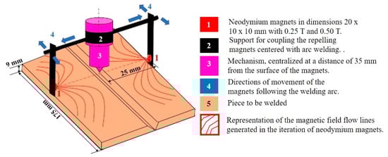
Figure 1.
Schematic illustration of the welding process with the addition of the external magnetic field.
To perform the microstructural characterization of the welded joint, it was polished by silicon carbide papers and diamond suspensions. The obtained micrographs from an optical micrograph (OM) and scanning electron microscope (SEM) were analyzed by Image-Pro Plus software in version 4.0 and manufacturer Media Cybernetics, Inc., Rockville, MD, USA. The scanning electron microscopy (SEM) of the cross-section of the welded joint was captured to assess the weld bead geometry. Forty OM images were taken, and with the help of mathematical software (Geogebra software, manufacturer University Salzburg and currently in Florida Atlantic University, Boca Raton, FL, USA), the fusion zone and the heat-affected zone (HAZ) were dimensioned.
To quantify the percentage of ferrite, the magnetic ferritoscope method of measurements were carried out. The Ferritoscope Fisher equipment (manufacturer Fisher do Brazil Measurement Technology, São Paulo, Brazil) de was used. A significant number of measurements on the region were obtained and the averaged values plotted to correlate the volumetric fraction with the applied magnetic external fields.
The mechanical properties of the welded joint were analyzed by the microhardness test, the dendritic structure characterization test, the Charpy impact test, and the corrosion test. The spacing between dendritic grains was measured from the obtained dendritic morphology. The Vickers microhardness test was carried out on each specimen along FZ (fusion zone), HAZ (heat-affected zone), and BM (base metal) at the distances of 0.20 mm and 0.35 mm from the sample surface. Two hardness tests were performed for each specimen, with eight indentations for each test. The distance between two Vickers microhardness points was 0.05 mm. For each sample, a 200 gf load was applied for 20 s.
The Charpy V-notch (CVN) test was carried out on the samples of 10 mm × 10 mm × 55 mm dimension at −20 °C according to the ASTM E2334 standard. Cracks generated in the samples were observed by SEM. The behara etchant was used to obtain the micrographs of the fusion zone. The images were obtained with magnification of 50× in the NIKON LV150 microscope (The equipment is of the Nikon brand, distributed in Brazil by the company BioLab Brazil in São Paulo, Brazil). The calculation of the pore area was performed by demarcating the pore areas of the micrograph with the threshold pixels in image J software (A computer program developed in National Institutes of Health, Bethesda, MD, USA) selected to post processing the image analysis. The evaluation of the average grain size (TG), was carried out using the Heyn intercept method or linear method (ASTM 2013). The samples were photographed with a 50-fold magnification in the NIKON LV150 microscope. According to the ASTM G5-94 standard, a total of twelve electrochemical measurements (polarization and impedance) were performed to assess the corrosion resistance of the samples. In these tests, the base metal and the welded region metal with a geometric area of 1 cm2 (longitudinal) were used as working electrodes along with a platinum counter electrode and a silver/silver chloride reference electrode. Before each test, the working electrodes were immersed in 3.5% NaCl solution. For each steel sample, the scan was executed from its corrosion potential to the pitting potential (Epite) at a rate of 0.333 mV·s−1 (1.2 V·h−1).
3. Results
3.1. Microstructure
With the plastic deformation, these steels exhibit an accelerated hardening, favoring a substantial increase in the strength as well as in the resistance in the extension until starting to narrow during the tensile test [12]. An analysis with SEM of the cross section of the welded joint allowed to evaluate the microstructure in the different zones. It was found that FZ and HAZ were composed of austenite grains (light regions) and delta ferrite (dark spots) [13]. Figure 2a displays the cross-sectional view of the weld, and Figure 2b reveals the surface morphologies of FZ, HAZ, and BM after chemical etching. It is observable that grains in BM were stretched to HAZ. In turn, HAZ was composed of coarse grains and grains stretched to FZ. Further, FZ consisted of columnar grains [14,15] and grains that grew in the same orientation of HAZ.
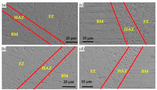
Figure 2.
Microstructure of the different zones of the samples. (a) B4 = 7.5 T, (b) B3 = 5.0 T, (c) B1 = 0 T, and (d) B2 = 2.5 T.
Figure 3 expresses that the solidification of AISI 304L steel occurred according to the following liquid reaction: Liq → Liq + δ → δ + γ. Hence, the microstructure of the investigated steel at room temperature consisted of an austenitic matrix and delta ferrite dendrites. Considering that the steel remained in the single-phase field of delta ferrite for a certain time, the slower the cooling rate, the longer the steel remained in this field and, consequently, the higher the delta ferrite fraction in the austenitic matrix.
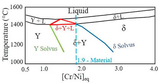
Figure 3.
Identification of the expected solidification path in the fusion zone of the material used in this study.
With macroscopic images obtained with optical microscopy and the software Image-Pro Plus 4.0, it was allowed to measure the dimensions and capture the geometry of the weld pool. According to Li et al. [11], an increase in the weld area results in a greater filling in the welded region. Moreover, a decrease of the weld width and an increase of the weld depth allow the reach of deep welds [11,13,16]. A good filling of FZ occurred by the weld metal. The increase in the weld area under the external magnetic field was 100% greater than that without the magnetic field. On the contrary, the width of FZ under the external magnetic field became 25% narrower than that without the magnetic field. Moreover, the geometry of the welded FZ under the external magnetic field was 3.0 mm deeper than that without the magnetic field. These results (show in Figure 4) were obtained by applying an external magnetic field of varying intensities during the welding process. The welding parameters were kept fixed to achieve the desired welding geometry before the welding process. Therefore, welding with an external magnetic field showed significant changes in the weld pool, that is, narrow and deep.
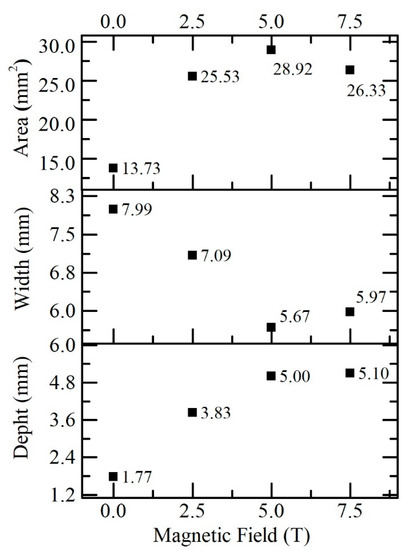
Figure 4.
Variations in the magnetic field versus fusion zone (FZ) geometry.
According to Li et al. [11] and Jeng et al. [17], it was observed that the fraction of delta ferrite decreased with the variation of the external magnetic field. Through the program called Image J, Figure 5, five regions were registered for each sample and the volumetric fractions of the ferrite were calculated; along with the results were calculated the means, standard deviation, and standard error for each process [18]. In Figure 5, therefore, a negative difference in the delta ferrite content of the welds was detected and the delta ferrite content differences between B1 and B2, B2 and B3, and B3 and B4 welds were 35.4%, 23.8%, and 28.12%, respectively. The external magnetic field slowed down the cooling rate and changed the microstructure of FZ. Figure 6 reveals that the dendritic spacing decreased with the increase of the external magnetic field. The primary dendritic spacings for B2, B3, and B4 welds were 12.13 µm, 11.44 µm, and 9.90 µm, respectively, and the corresponding secondary dendritic spacings were 8.00 µm, 5.61 µm, and 3.81 µm, respectively. This effect influenced the mechanical properties of the welded FZ with greater crack resistance and ductility. The dendritic spacing λ2 manifested a greater tendency to refinement as compared with the dendritic spacing λ1. Hence, the external magnetic field allowed control of the dendritic spacing in the welding process [3].
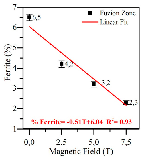
Figure 5.
Variations of the external magnetic field versus the measured ferrite fraction volumes.
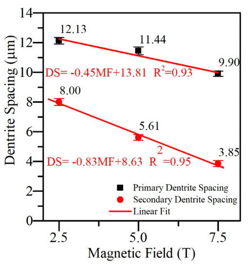
Figure 6.
Variations in the external magnetic field versus the primary and secondary dendritic spacing.
3.2. Mechanical
The Vickers microhardness in FZ under the external magnetic field was relatively higher than that without the magnetic field owing to the refinement and uniformity of the microstructure [19,20,21,22].
For the Vickers microhardness test, the distance between two Vickers microhardness points was 0.05 mm. For each sample, a load of 200 gf was applied for 20 s. In Figure 7, the welding without magnetic field has a Vickers microhardness with no value (on average) B1 = 330 HV (depth 0.20 mm) and B1 = 284 HV 0.35 mm (depth 0.35 mm) and welding with external magnetic field value (on average) (at depth 0.20 mm) B2 = 223 HV, B3 = 314 HV, and B5 = 185 HV (at depth 0.35) and B2 = 206 HV, B3 = 201 HV, and B4 = 164 HV, which allows verify that the weld, without an external magnetic field, presents the highest values of Vickers microhardness at different depths. Welding without a magnetic field promotes more solid state and, therefore, there is more ferrite within the FZ. Li et al. [10] states that a ferrite acts as a second strengthening agent, and thus increases the duration within the melt pool.
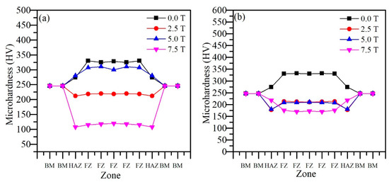
Figure 7.
Evolution of Vickers microhardness at different depths in the weld bead and external magnetic field. (a) At a depth of 0.20 mm and (b) at a depth of 0.35 mm. HAZ, heat-affected zone; BM, metal base; FZ, fusion zone.
It is evident from Figure 7a that, at a depth of 0.20 mm, FZ presented a higher Vickers microhardness value for both B1 and B3 welds. In Figure 7b, a similar trend is observed for the B1 weld. Hence, under the external magnetic field, at a depth of 0.35 mm, the FZ had a lower Vickers microhardness value than BM.
In the B2 weld, the Vickers microhardness values of BM and FZ at a depth of 0.35 mm were 246 HV and 213 HV, respectively. In the B3 weld, the values were 246 HV and 210 HV, respectively, and in the B4 weld, the values were 246 HV and 176 HV, respectively. However, in the B4 weld, the Vickers microhardness value of FZ at a depth of 0.35 mm was higher than that at a depth of 0.20 mm.
In the B4 weld, the Vickers microhardness values of FZ at the depths of 0.35 mm and 0.20 mm were 176 HV and 120 HV, respectively. According to Chen et al. [23], the values of Vickers microhardness are the same that occur owing to the uniformity of grains caused by the magnetic effect on FZ. Magnetic agitation inside the FZ is responsible for the formation of smaller dendritic grains, favoring the appearance of lower values of Vickers microhardness. The Vickers microhardness tests in FZ, HAZ, and BM were carried out according to the procedure described by Demarque et al. [24].
The material in the fusion zone melted, consequently eliminating the cold work-hardening effect. Besides, the formation of a softer structure composed of austenite and ferrite also leads to a decrease in microhardness [10]. Figure 8 presents the Vickers microhardness values of FZ under each magnetic field at the depths of 0.20 mm and 0.30 mm from the weld bead surface. Under B1 = 0.0 T, the Vickers microhardness values of FZ at the depths of 0.20 mm and 0.30 mm were 328 HV and 332 HV, respectively (Figure 8a). Under B2 = 2.5 T, the values were 220 HV and 213 HV, respectively (Figure 8c). Under B3 = 5.0 T, the values were 315 HV and 210 HV, respectively (Figure 8b). Under B5 = 7.5 T, the values were 120 HV and 172 HV, respectively (Figure 8d). Hence, it can be inferred that, under the external magnetic field, FZ had lower microhardness values [24,25].
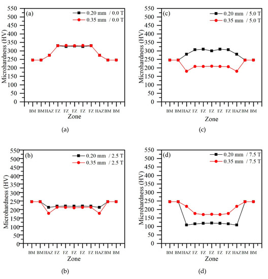
Figure 8.
(a) Vickers microhardness for B = 0.0 T, (c) Vickers microhardness for B = 2.5 T, (b) Vickers microhardness for B = 5.0 T, and (d) Vickers microhardness for B = 7.5 T.
Bachmann et al. [8] states that, in the interior of the weld pool, below the surface of the welded part in the weld pool, there is a variation in the speed of the liquid with a magnetic field. In Figure 7a and Figure 8b, it is possible to observe that the depth of 0.20 mm (surface) has an exception, that is, the Vickers microhardness has the highest value in comparison with the BM values. The increase in the microhardness value can be justified by the possible reduction in speed below the weld surface.
In addition to the downward trend in Vickers microhardness values, with the external magnetic field applied, the fluctuation in hardness across the fusion zone was smaller, which might indicate a more uniform microstructure and finer grains [10].
Charpy’s tests were performed at a temperature of −20 °C for welding without a magnetic field and another with a magnetic field. These tests allowed the following results. Figure 9a,b show the effect of applied magnetic field on the fractures during the Charpy test, respectively. The effects on the microstructures of the fractured surface of the welded specimen are evident (micro-voids, voids, and flat surfaces are marked by blue circles, yellow circles, and red rectangles, respectively). This aspect of the fracture is typical of ductile materials.
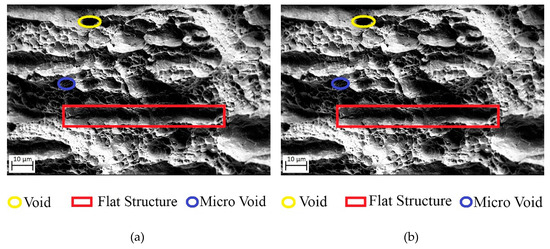
Figure 9.
Evaluation of the microstructure via scanning electron microscopy (SEM) after the Charpy test. (a) Without the addition of the magnetic field and (b) with the addition of the external magnetic field.
After the Charpy test, it is expected that the microstructure in the fracture region presents a similar aspect to the FZ microstructure and the ferrite is responsible for the toughness of the material [26,27,28]. As previously stated, welding without a magnetic field has a higher percentage of ferrite compared with welding with a magnetic field. In addition, the volume of pores is another element that attests to the occurrence of ductility of the material.
Through the program called Image J, Figure 10, five regions were registered for each sample and the volumetric fractions and diameter of the pores were calculated; along with the results were calculated the means, standard deviation, and standard error for each process [18]. Figure 10 shows that the weld without an external magnetic field B1 = 0 T has 28.50 µm and 69.21 µm of the pore diameter and the fracture pore volume fraction in the FZ, respectively. The weld with a magnetic field B4 = 7.5 T has 6.68 µm and 4.02 µm of the pore diameter and the fracture pore volume fraction in the FZ, respectively. These values reveal a reduction of 76.63% and 94.2% in the diameter and the volume fraction of the fracture pore in the FZ of the weld with an external magnetic field, respectively.
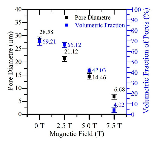
Figure 10.
Study of the pore diameter and volumetric fraction of the microstructure after the Charpy test.
It is also evident in Figure 10 that, with the increase of the intensity of the external magnetic field, the size and the volumetric fraction of the diminished pores can influence the FZ toughness.
Figure 11 expresses that, although the percentage of density diameter decreases with the increase of the magnetic field, this behavior does not cause a significant difference in the absorbed energy or better, as the changes in density occurring with a variation of the magnetic field do not affect the energy absorption during the Charpy energy test performed at the FZ. Therefore, welding with an external magnetic field maintained the weld ductility, when the intensity of the external magnetic field increased [29,30].
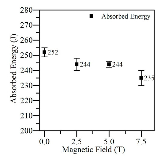
Figure 11.
Energy absorbed with the variation of the external magnetic field obtained by the Charpy test.
In this same sense, one can observe a small energy difference in the welds . The difference of the samples is negligible for this material. This small difference for such high ductility austenitic stainless steel could not be attributed to the variation of the magnetic field. Therefore, we attributed these differences in the measurements to the uncertainty of the measurement method. In addition to this difference, when looking at Figure 11, error causes one point to overlap the other. This behavior allows to observe that the welding with an external magnetic field does not alter the ductility of the FZ.
Pitting potential (Ep) can be defined as the potential at which a passive film is destroyed, and an intense localized attack occurs. The resistance to pitting corrosion increases with the increasing Ep value, thus maintaining a passive condition of the surface through a potential from corrosion (Ecorr) [11]. Figure 12 presents the corrosion potentials (Ecorr) and corrosion currents (Icorr) for welding under 0.0 T (−0.04 V and 7.2 × 10⁻⁵ log A/cm2, respectively), 2.5 T (−0.05 V and 7.8 × 10⁻⁵ log A/cm2, respectively), 5.0 T (−0.12 V and 6.2 × 10⁻⁵ log A/cm2, respectively), and 7.5 T (−0.22 V and 6.8 × 10⁻⁵ log A/cm2, respectively), thus it is clear that, with the increase of the external magnetic field intensity, the Ecorr value decreased gradually [28,31,32].
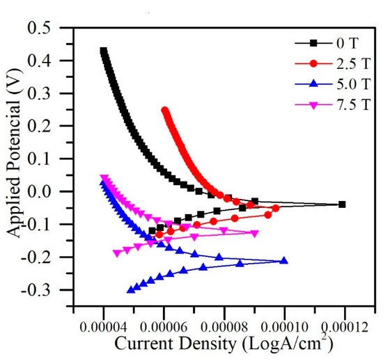
Figure 12.
Current density versus the applied potential to the addition of the external magnetic field.
The Icorr value under B2 = 2.5 T was higher than that under B1 = 0.0 T. According to Curiel et al. [33], welding is not so significant for corrosion. Curiel et al. and Pedrini et al. [33,34] found that the axial magnetic field applied during welding changed the electrochemical behavior of the samples taken from FZ. The corrosion potentials of the samples welded under the magnetic field moved to more negative values than that of the sample welded without a magnetic field. Curiel et al. [33] reported a depolarized cathodic reaction and passive behavior of welded AISI 304 in a 3.5% NaCl solution and associated that behavior to the presence of delta ferrite. The fact that ferrite is magnetic and a greater or lesser fraction of it will influence the potential. Riuper et al. [28] observed that the decrease in Ecorr occurred as a result of the decrease in dendritic spacing, indicating that a more refined dendritic spacing contributed to the reduction of the corrosion potential.
4. Conclusions
To evaluate the influences of an external magnetic field on TIG welding, the dendritic structure characterization test, the Vickers microhardness test, the Charpy impact test, and the corrosion test were performed, and the main observations are presented below.
With the values obtained from the variation of the magnetic field against the geometry of the fusion zone, it can be expressed that the addition of the external magnetic field contributed to the formation of the largest fusion zone, which became more elongated and narrower with the variation of the magnetic field. Welding with an external magnetic field, B4 = 7.5 T increased the depth of the weld pool by about 280% and decreased the width by about 80%. Therefore, the magnetic field is a major advance in obtaining deep welds.
With the values obtained from the variation of the magnetic flux density against the percentage of delta ferrite, it can be posited that a decrease in the ferrite percentage occurred in the fusion zone under the magnetic field, thus causing grain refinement and a decrease in the dendritic spacing in the weld bead.
The fusion zone shows lower Vickers microhardness under the external magnetic field at a depth of 0.35 mm. In addition, a weld depth of 0.35 mm features Vickers microhardness less than a depth of 0.20 mm. In this sense, the addition of the external magnetic field, in the welding process, tends to decrease the value of the Vickers microhardness in the weld pool and in the deep regions of the surface. It was possible to observe that the Vickers microhardness point values do not fluctuate, that is, a given Vickers microhardness point does not present a disparity between the predecessor and successor points.
The FZ, at the depths of 0.35 mm and 0.20 mm, of the B2 = 2.5 T weld, exhibit similar values of Vickers microhardness. Thus, with respect to the value of Vickers microhardness, B2 welding does not show marked variation in these depths.
A microstructural evaluation revealed that the fusion zone has high toughness. With a variation of the external magnetic field, resistance of the melting zone was constant. Therefore, welding with a magnetic field did not show significant variation in the toughness value of the fusion zone, showing voids, micro voids, and flat regions in the microstructure.
The pore volume fraction and the pore diameter manifested a decreasing trend with the variation of the external magnetic field. When the pore diameter was large, the pore volume fraction was high, and vice-versa.The welding with external magnetic field (B4 = 7.5 T) presented 5% of the pore volumetric fraction of the welding without magnetic field (B1 = 0 T). Regarding the pore diameter, the B4 welding showed a 73% reduction in welding without adding the magnetic field. In this sense, the variation of the external magnetic field tends to decrease the pore diameter and the volume of the pore volume fraction.
With the values obtained from the variation of the current density against the applied potential, it can be propounded that the presence of the external magnetic field caused a decrease in the corrosion potential (owing to the lower ferrite content in the fusion zone).
Welding B3 = 5.0 T shows the FZ with the best filling, the same absorption B2 = B3 = B4, while at depth 0.35 mm it presented the same value as the Vickers microhardness of weld B2. Therefore, B3 welding presented the ideal characteristics for welding with a magnetic field.
Author Contributions
A.V.d.Q. conceived and design the experimental procedure and writing; M.T.F., L.S. and R.D. contributed to the experimental analysis; C.R.X. and J.A.d.C. contributed to the experimental planning, discussion, and conclusions; A.V.d.Q. wrote the paper. All authors have read and agreed to the published version of the manuscript.
Funding
Coordination of support of personnel for high education (CAPES), Carlos Chagas Filho foundation (FAPER-Process No E-26/202.888/2018 Grant: 239505).
Acknowledgments
The authors thank the funding agencies: Coordination of Improvement of Higher Education Personnel, (CAPES), Ministry of Science and Technology. They also thank the Metallurgical Engineering graduate program of the Fluminense Federal University for the technical support.
Conflicts of Interest
The authors declare no conflict of interest.
References
- Khan, M.; Romoli, L.; Fiaschi, M.; Dini, G.; Sarri, F. Experimental design approach to the process parameter optimization for laser welding of martensitic stainless steels in a constrained overlap configuration. Opt. Laser Technol. 2011, 43, 158–172. [Google Scholar] [CrossRef]
- Yao, Q.; Luo, Z.; Li, Y.; Yan, F.; Duan, R. Effect of electromagnetic stirring on the microstructures and mechanical properties of magnesium alloy resistance spot weld. Mater. Des. 2014, 63, 200–207. [Google Scholar] [CrossRef]
- Cao, L.; Yang, Y.; Jiang, P.; Zhou, Q.; Mi, G.; Gao, Z.; Rong, Y.; Wang, C. Optimization of processing parameters of AISI 316L laser welding influenced by external magnetic field combining RBFNN and GA. Results Phys. 2017, 7, 1329–1338. [Google Scholar] [CrossRef]
- Silva, K.B. Study of TIG Arc Physics and its Implications for Weld Bead Morphology with the Presence of External Longitudinal Magnetic Fields. Available online: https://repositorio.ufsc.br/handle/123456789/202332 (accessed on 5 December 2019).
- Baldan, E.L.; Melado, M.C. Parameter Evaluation in Submerged Arc Welding. Available online: http://mecanica.ufes.br/sites/engenhariamecanica.ufes.br/files/field/anexo/2007-1_marcos_melado_e_ednaldo_baldan.pdf (accessed on 21 August 2007).
- De Almeida, L.F.C.B. Evaluation of the Influence of Mechanical Vibration Application on the Microstructure and Mechanical Characteristics of Stainless Steel Joints Welded by the FCAW Process. Ph.D. Thesis, Universidade de São Paulo, Paulo, Brazil, 11 December 2015; p. 133. [Google Scholar] [CrossRef]
- Cunha, T.V.; Bohórquez, C.E.N. Ultrasound in Arc Welding-A Review of Application Methods and its Effects. Soldag. Insp. 2014, 19, 221–230. [Google Scholar] [CrossRef]
- Bachmann, M.; Avilov, V.; Gumenyuk, A.; Rethmeier, M. Numerical assessment and experimental verification of the influence of the Hartmann effect in laser beam welding processes by steady magnetic fields. Int. J. Therm. Sci. 2016, 101, 24–34. [Google Scholar] [CrossRef]
- Li, Y.; Luo, Z.; Yan, F.; Duan, R.; Yao, Q. Effect of external magnetic field on resistance spot welds of aluminum alloy. Mater. Des. 2014, 56, 1025–1033. [Google Scholar] [CrossRef]
- Li, Y.B.; Zhang, Q.X.; Qi, L.; David, S.A. Improving austenitic stainless steel resistance spot weld quality using external magnetic field. Sci. Technol. Weld. Join. 2018, 23, 619–627. [Google Scholar] [CrossRef]
- Li, Y.-B.; Shen, Q.; Lin, Z.Q.; Hu, S.J. Quality improvement in resistance spot weld of advanced high strength steel using external magnetic field. Sci. Technol. Weld. Join. 2011, 16, 465–469. [Google Scholar] [CrossRef]
- Da Fonseca, G.S.; De Oliveira, S.C.; Chaves, J.G.; Leite, P.P.; Da Silva, F.R.F.; Lopes, L.C.R. Study of Martensitic Transformation in 304L Austenitic Stainless Steel after Tensile and Low Cycle Fatigue Tests. J. Mater. Sci. Res. 2019, 9, 22. [Google Scholar] [CrossRef]
- Azevedo, A.G.L.; Ferraresi, V.A.; Farias, J.P. Welding of a Ferritic Stainless Steel with the A-Tig Process. Soldagem Insp. São Paulo 2009, 14, 2–9. [Google Scholar] [CrossRef]
- Xu, Z.; Li, Z.; Ma, L.; Cao, Z.; Yang, J.; Yan, Y. Dynamic Behavior of Solder Filling during Ultrasonic Soldering. Weld. J. 2019, 98, 194S–203S. [Google Scholar]
- Rao, T.; Krishna, G.; Kumar, M. Investigation of Microstructure and Mechanical Properties of MIG Welded Mild Steel Plates. Ann. Chim. Sci. Mat. 2019, 43, 257–263. [Google Scholar] [CrossRef]
- Natividad, C.; García, R.; López, V.H.; Contreras, A.; Salazar, M. Metallurgical Characterization of API X65 Steel Joint Welded by MIG Welding Process with Axial Magnetic Field. Mater. Res. 2017, 20, 1174–1178. [Google Scholar] [CrossRef]
- Jeng, S.-L.; Su, D.-P.; Lee, J.-T.; Huang, J.-Y. Effects of Electromagnetic Stirring on the Cast Austenitic Stainless Steel Weldments by Gas Tungsten Arc Welding. Metals 2018, 8, 630. [Google Scholar] [CrossRef]
- Abramoff, M.D.; Magalhães, P.J.; Ram, S.J. Image Processing with ImageJ. Biophotonics Int. 2004, 11, 36–42. [Google Scholar]
- Hernandez-Trujillo, S.L.; López-Morelos, V.H.; García-Hernández, R.; García-Rentería, M.A.; Ruiz, A. Effect of Electromagnetic Field on the Microstructure and Mechanical Properties of the Dissimilar 2205/316L Welded Joint. In Procedings of the 17th International Conference on New Trends in Fatigue and Fracture; Springer: Cham, The Switzerland, 17–20 July 2018; pp. 247–254. [Google Scholar]
- Garcia, R.; Cortes, R.; García, D.L.; López, V.H. Effect of the Perpendicular Electromagnetic Field in the 304 Austenitic Stainless Steel Welding in a Single Pass. Mater. Charact. 2015, 119–127. [Google Scholar] [CrossRef]
- Garcia-Renteria, M.-A.; López-Morelos, V.; González-Sánchez, J.; Hernandez, R.G.; Dzib-Pérez, L.; Lopez, F.F.C. Effect of electromagnetic interaction during fusion welding of AISI 2205 duplex stainless steel on the corrosion resistance. Appl. Surf. Sci. 2017, 396, 1187–1200. [Google Scholar] [CrossRef]
- Rong, Y.; Xu, J.; Cao, H.; Zheng, H.; Huang, Y.; Zhang, G. Influence of steady magnetic field on dynamic behavior mechanism in full penetration laser beam welding. J. Manuf. Process. 2017, 26, 399–406. [Google Scholar] [CrossRef]
- Chen, R.; Jiang, P.; Shao, X.; Mi, G.; Wang, C. Effect of static magnetic field on microstructures and mechanical properties of laser-MIG hybrid welding for 304 stainless steel. Int. J. Adv. Manuf. Technol. 2017, 91, 3437–3447. [Google Scholar] [CrossRef]
- Demarque, R.; Dos Santos, E.; Silva, R.; De Castro, J. Evaluation of the effect of the thermal cycle on the characteristics of welded joints through the variation of the heat input of the austhenitic AISI 316L steels by the GMAW process. Sci. Technol. Mater. 2018, 30, 51–59. [Google Scholar] [CrossRef]
- Chelah, N.; Hussin, M.H. Magnetic Field Effectson 4G Positions in Shielded Metal Arc Welding Process. Int. J. Eng. Adv. Technol. 2020, 9, 694–703. [Google Scholar]
- Nunes, C.J.A.; Martins, C.D. Effects of Solubilization Treatment and Thermal Aging on Microstructure Corrosion Resistance of a Welded Joint with AISI 304L Steel. Available online: http://www.cefet-rj.br/attachments/article/2943/Projeto Final 2017_2 Efeitos do Tratamento de Solubilização e Envelhecimento Térmico na Microestrutura e Resistência a Corrosão de Junta Soldada Aço AISI 304L.pdf (accessed on 13 January 2018).
- Arturo, G.R.M.; Hugo, L.M.V.; Rafael, G.H.; Egberto, B.B.; Antonio, G.S.J. Electrochemical Characterization of AISI 2205 Duplex Stainless Steel Welded Joints with Electromagnetic Interaction. Procedia Mater. Sci. 2015, 8, 950–958. [Google Scholar] [CrossRef]
- Dar, Y.A.; Singh, C.; Farooq, Y. Effects of External Magnetic Field on Welding Arc of Shielded Metal Arc Welding. Indian J. Appl. Res. 2011, 4, 200–203. [Google Scholar] [CrossRef]
- Osório, W.R.; Garcia, L.R.; Peixoto, L.C.; Garcia, A. The influence of macrosegregation and variation of dendritic spacing on the corrosion resistance of Al-4.5%Cu alloy. Materia 2008, 13, 542–552. [Google Scholar] [CrossRef]
- Senapati, A.; Mohanty, S.B. Effects of External Magnetic Field on Mechanical properties of a welded M.S metal through Metal Shield Arc Welding. Int. J. Eng. Trends Technol. 2014, 10, 297–303. [Google Scholar] [CrossRef]
- Sant’anna, A.M.S.; Bastos, I.N.; Fonseca, M.P.C. Effect of Hydrogenation on the Mechanical Properties of Steel API 5L X-65. Proceeding of the Brazilian Congress on Manufacturing Engineering, Associação Brasileira de Engenharia e Ciências Mecânicas, Ribeirão Preto, Brazil, 20–24 May 2013. [Google Scholar]
- Cardoso, S.P.; Dos Reis, F.A.; Massapust, F.C.; Costa, J.D.F.; Tebaldi, L.S.; De Araújo, L.F.L.; Da Silva, M.V.A.; De Oliveira, T.S.; Gomes, J.A.D.C.P.; Hollauer, E. Avaliação de indicadores de uso diverso como inibidores de corrosão. Química Nova 2005, 28, 756–760. [Google Scholar] [CrossRef][Green Version]
- Curiel, F.; Garcia, R.; Lopez, F.F.C.; González-Sánchez, J. Effect of magnetic field applied during gas metal arc welding on the resistance to localised corrosion of the heat affected zone in AISI 304 stainless steel. Corros. Sci. 2011, 53, 2393–2399. [Google Scholar] [CrossRef]
- Pedrini, L.T.; Maziero, R.; Gontijo, L.C.; Altoé, J.A.F. Corrosion resistance analysis of AISI 304L. Proceeding of the ABM Proceedings, ABM WEEK, Rio de Janeiro, Brazil, 17–21 August 2015. [Google Scholar]
© 2020 by the authors. Licensee MDPI, Basel, Switzerland. This article is an open access article distributed under the terms and conditions of the Creative Commons Attribution (CC BY) license (http://creativecommons.org/licenses/by/4.0/).