Mechanical Properties of CoCr Dental-Prosthesis Restorations Made by Three Manufacturing Processes. Influence of the Microstructure and Topography

 , ,
, , 
 and
and 
Abstract
1. Introduction
2. Materials and Methods
2.1. Model Preparation
2.2. Study Groups Assignment
- - Group A: Cr-Co frameworks manufactured using wax-lost casting method. A total of nine models were performed (n = 9);
- - Group B: Cr-Co frameworks manufactured using a 5-axis CADCAM milling system. A total of nine models were performed (n = 9);
- - Group C: Cr-Co frameworks manufactured using Laser Sintering system. A total of nine models were performed (n = 9).
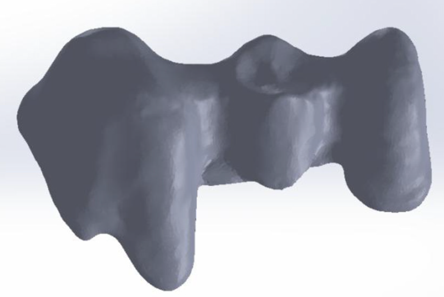
2.3. Structure Design and CADCAM Manufacturing
- - Thickness of 0.5 mm around the entire outline of the structure;
- - Pontic in FDP position (n°15) with a convex shape on its cervical surface and 1 mm away from the edentulous crest;
- - Application of a space of 50 µm on the dies to 1 mm form the location of the finishing line.
2.4. Surface Roughness
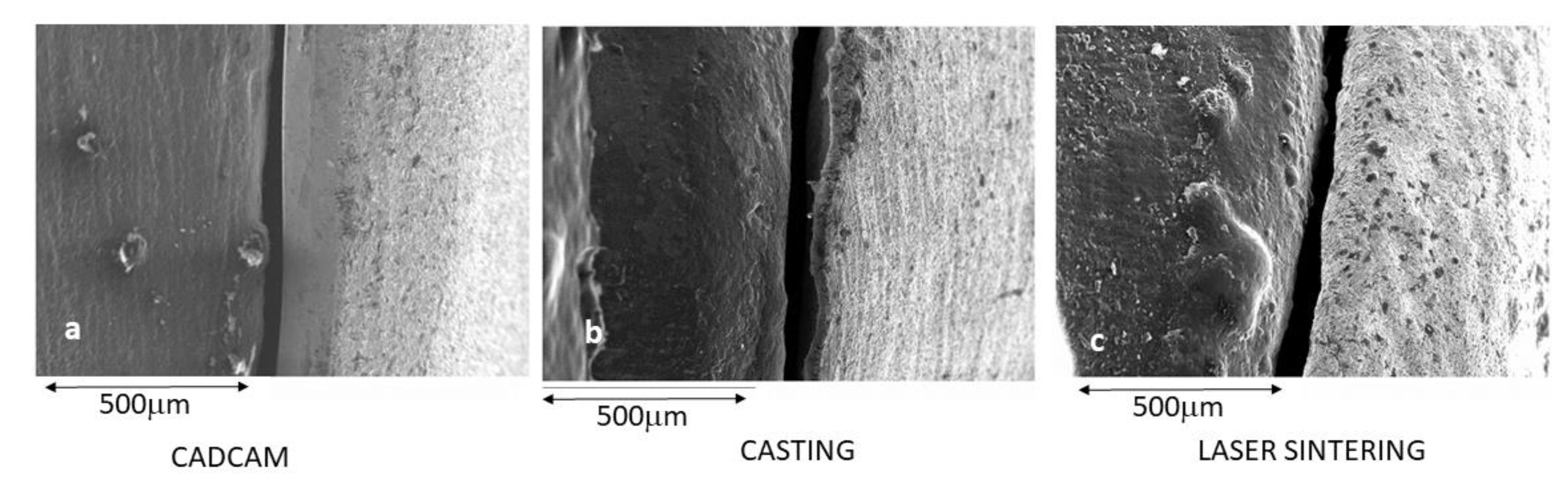
2.5. Surface Morphology and Marginal Gap Determination.
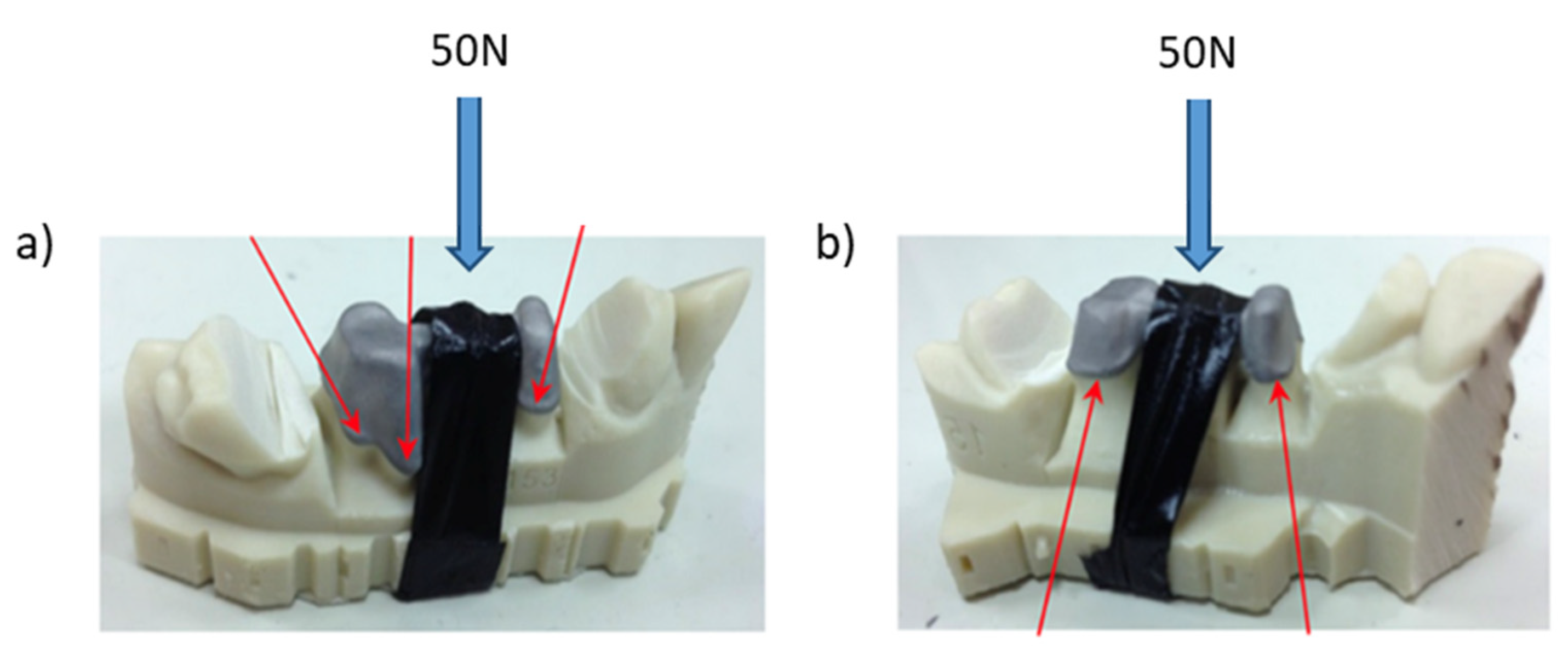
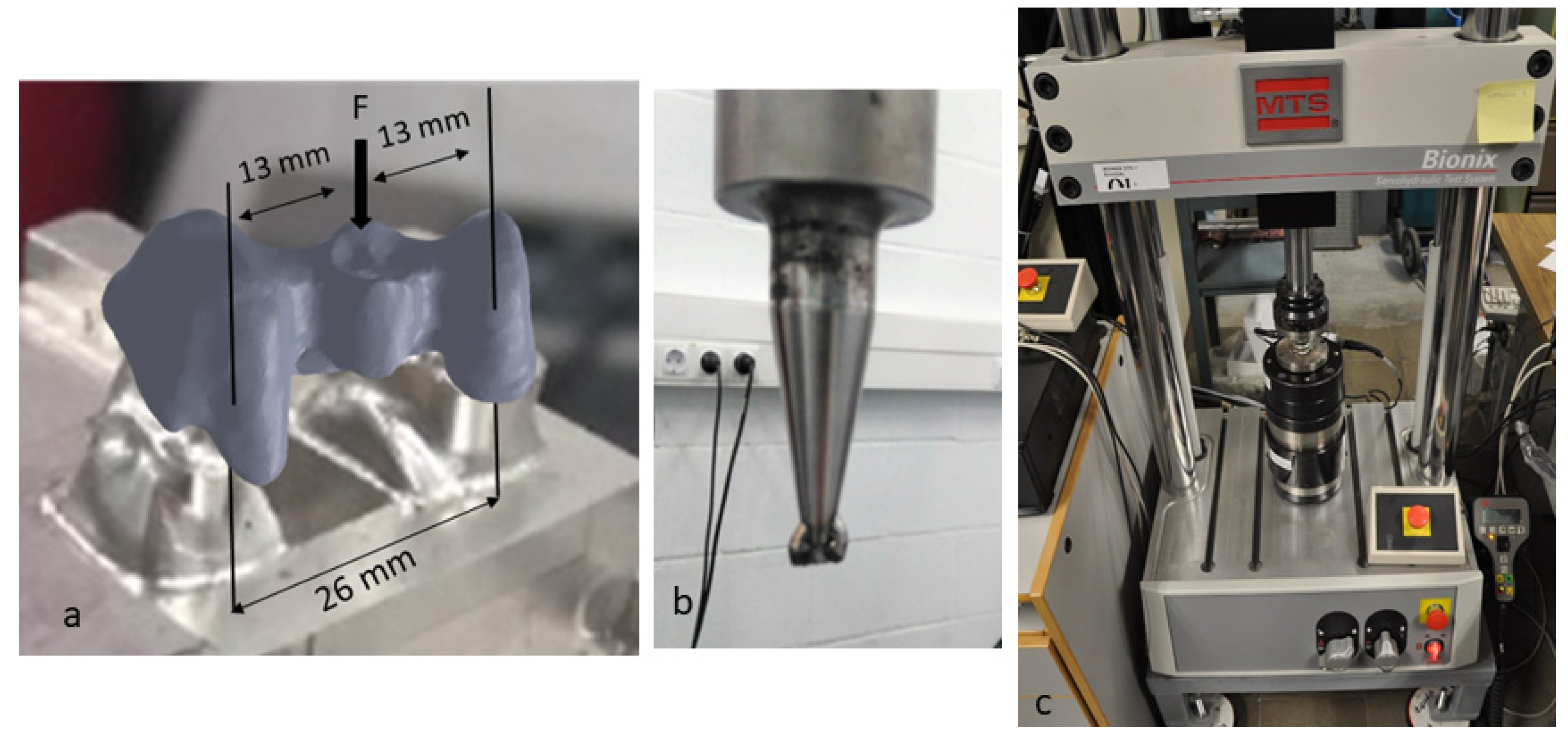
2.6. Mechanical Testing
2.7. Statistical Analysis
3. Results
4. Discussion
5. Conclusions
Author Contributions
Funding
Acknowledgments
Conflicts of Interest
References
- Mörmann, W.H.; Brandestini, M.; Lutz, F. The Cerec system: Computer-assisted preparation of direct ceramic inlays in 1 setting. Die Quintessenz 1987, 38, 457–470. [Google Scholar] [PubMed]
- Sannino, G.; Germano, F.; Arcuri, L.; Bigelli, E.; Arcuri, C.; Barlattani, A. CEREC CAD/CAM Chairside System. Oral Implant. 2015, 7, 57–70. [Google Scholar]
- Mangano, C.; Gandolfi, A.; Luongo, G.; Logozzo, S. Intraoral scanners in dentistry: A review of the current literature. BMC Oral Heal. 2017, 17, 149. [Google Scholar] [CrossRef] [PubMed]
- Tapie, L.; Lebon, N.; Mawussi, B.; Chabouis, H.F.; Duret, F.; Attal, J.-P. Understanding dental CAD/CAM for restorations—The digital workflow from a mechanical engineering viewpoint. Int. J. Comput. Dent. 2015, 18, 21–44. [Google Scholar]
- Tinschert, J.; Natt, G.; Hassenpflug, S.; Spiekermann, H. Status of current CAD/CAM technology in dental medicine. Int. J. Comput. Dent. 2004, 7, 25–45. [Google Scholar]
- Zimmermann, M.; Mehl, A.; Mörmann, W.H.; Reich, S. Intraoral scanning systems—A current overview. Int. J. Comput. Dent. 2015, 18, 101–129. [Google Scholar]
- Rekow, E.D. Dental CAD-CAM Systems: What Is the State of the Art? J. Am. Dent. Assoc. 1991, 122, 42–48. [Google Scholar] [CrossRef]
- Rekow, E.; Erdman, A.; Riley, D.; Klamecki, B. CAD/CAM for dental restorations-some of the curious challenges. IEEE Trans. Biomed. Eng. 1991, 38, 314–318. [Google Scholar] [CrossRef]
- Roediger, M.; Schneider, L.; Rinke, S. Influence of Material Selection on the Marginal Accuracy of CAD/CAM-Fabricated Metal- and All-Ceramic Single Crown Copings. BioMed. Res. Int. 2018, 2018, 1–8. [Google Scholar] [CrossRef]
- Sannino, G.; Gloria, F.; Schiavetti, R.; Ottria, L.; Barlattani, A. Dental Wings CAD/CAM system precision: An internal and marginal fit sperimental analisys. Oral Implant. 2010, 2, 11–20. [Google Scholar]
- Mah, J.K.; Huang, J.C.; Choo, H. Practical Applications of Cone-Beam Computed Tomography in Orthodontics. J. Am. Dent. Assoc. 2010, 141, 7S–13S. [Google Scholar] [CrossRef] [PubMed]
- Hong, J.-S.; Oh, K.-M.; Kim, B.-R.; Kim, Y.-J.; Park, Y.-H. Three-dimensional analysis of pharyngeal airway volume in adults with anterior position of the mandible. Am. J. Orthod. Dentofac. Orthop. 2011, 140, e161–e169. [Google Scholar] [CrossRef] [PubMed]
- MacLeod, I.; Heath, N. Cone-beam computed tomography (CBCT) in dental practice. Dent. Update 2008, 35, 590–598. [Google Scholar] [CrossRef] [PubMed]
- Scarfe, W.C.; Levin, M.D.; Gane, D.; Farman, A.G. Use of Cone Beam Computed Tomography in Endodontics. Int. J. Dent. 2010, 2009, 1–20. [Google Scholar] [CrossRef]
- Quereshy, F.A.; Savell, T.A.; Palomo, J.M. Applications of Cone Beam Computed Tomography in the Practice of Oral and Maxillofacial Surgery. J. Oral Maxillofac. Surg. 2008, 66, 791–796. [Google Scholar] [CrossRef]
- Swain, M.V.; Xue, J. State of the art of Micro-CT applications in dental research. Int. J. Oral Sci. 2009, 1, 177–188. [Google Scholar] [CrossRef]
- Dong, G.; Dong, Q.; Liu, Y.; Lou, B.; Feng, J.; Wang, K.; Zhou, X.; Wu, H. High-resolution micro-CT scanning as an innovative tool for evaluating dental hard tissue development. J. Appl. Clin. Med. Phys. 2014, 15, 335–344. [Google Scholar] [CrossRef]
- Ortorp, A.; Jonsson, D.; Mouhsen, A.; Von Steyern, P.V. The fit of cobalt–chromium three-unit fixed dental prostheses fabricated with four different techniques: A comparative in vitro study. Dent. Mater. 2011, 27, 356–363. [Google Scholar] [CrossRef]
- Cho, S.-H.; Schaefer, O.; Thompson, G.A.; Guentsch, A. Comparison of accuracy and reproducibility of casts made by digital and conventional methods. J. Prosthet. Dent. 2015, 113, 310–315. [Google Scholar] [CrossRef]
- Nawafleh, N.; Mack, F.; Evans, J.; Mackay, J.; Hatamleh, M.M. Accuracy and Reliability of Methods to Measure Marginal Adaptation of Crowns and FDPs: A Literature Review. J. Prosthodont. 2013, 22, 419–428. [Google Scholar] [CrossRef]
- Koutsoukis, T.; Zinelis, S.; Eliades, G.; Al-Wazzan, K.; Al Rifaiy, M.; Al Jabbari, Y.S. Selective Laser Melting Technique of Co-Cr Dental Alloys: A Review of Structure and Properties and Comparative Analysis with Other Available Techniques. J. Prosthodont. 2015, 24, 303–312. [Google Scholar] [CrossRef] [PubMed]
- Sofia, D.; Barletta, D.; Poletto, M. Laser sintering process of ceramic powders: The effect of particle size on the mechanical properties of sintered layers. Addit. Manuf. 2018, 23, 215–224. [Google Scholar] [CrossRef]
- Sofia, D.; Granese, M.; Barletta, D.; Poletto, M. Laser Sintering of Unimodal Distributed Glass Powders of Different Size. Procedia Eng. 2015, 102, 749–758. [Google Scholar] [CrossRef]
- Ferreira, T.J.; Vieira, M.T.; Costa, J.; Gato, P.T. Manufacturing Dental Implants using Powder Injection Molding. J. Orthod. Endod. 2016, 2, 1–21. [Google Scholar]
- Ataee, A.; Li, Y.; Song, G.; Wen, C. Metal Scaffolds Processed by Electron Beam Melting for Biomedical Applications. In Metallic Foam Bone. Processing, Modification and Characterization and Properties; Elsevier: London, UK, 2017; pp. 83–110. [Google Scholar]
- Suresh, G.; Narayana, L.; Kedar, M. Laser Engineered Net Shaping Process in Development of Medical Implants: An Overview. J. Adv. Res. Dynam. Control Syst. 2017, 9, 745–756. [Google Scholar]
- Hero, H.; Syverud, M.; Gjonnes, J.; Horst, J. Ductility and structure of some cobalt-base dental casting alloys. Biomaterials 1984, 5, 201–208. [Google Scholar] [CrossRef]
- Qiu, J.; Yu, W.Q.; Zhang, F.Q.; Smales, R.J.; Zhang, Y.L.; Lu, C.H. Corrosion behaviour and surface analysis of a Co-Cr andtwo Ni-Cr dental alloys before and after simulated porcelainfiring. Eur. J. Oral Sci. 2011, 119, 94–101. [Google Scholar] [CrossRef]
- Lewis, A.J. Radiographic evaluation of porosities in removable partial denture castings. J. Prosthet. Dent. 1978, 39, 278–281. [Google Scholar] [CrossRef]
- Van Noort, R.; Lamb, D.J. A scanning electron microscope study of Co-Cr partial dentures fractured in service. J. Dent. 1984, 12, 122–126. [Google Scholar] [CrossRef]
- Naert, I.; Van Der Donck, A.; Beckers, L. Precision of fit and clinical evaluation of all-ceramic full restorations followed between 0.5 and 5 years. J. Oral Rehabilitation 2005, 32, 51–57. [Google Scholar] [CrossRef]
- Sorensen, S.E.; Larsen, I.B.; Jörgensen, K.D. Gingival and alveolar bone reaction to marginal fit of subgingival crown margins. Eur. J. Oral Sci. 1986, 94, 109–114. [Google Scholar] [CrossRef] [PubMed]
- Felton, D.; Kanoy, B.; Bayne, S.; Wirthman, G. Effect of in vivo crown margin discrepancies on periodontal health. J. Prosthet. Dent. 1991, 65, 357–364. [Google Scholar] [CrossRef]
- Jacobs, M.S.; Windeler, A.S. An investigation of dental luting cement solubility as a function of the marginal gap. J. Prosthet. Dent. 1991, 65, 357–364. [Google Scholar] [CrossRef]
- Martins, L.M.; Lorenzoni, F.C.; De Melo, A.O.; Da Silva, L.M.; De Oliveira, J.L.G.; De Oliveira, P.C.G.; Bonfante, G. Internal fit of two all-ceramic systems and metal-ceramic crowns. J. Appl. Oral Sci. 2012, 20, 235–240. [Google Scholar] [CrossRef]
- Kim, K.-B.; Kim, J.-H.; Kim, W.-C.; Kim, H.-Y.; Kim, J.-H. Evaluation of the marginal and internal gap of metal-ceramic crown fabricated with a selective laser sintering technology: Two- and three-dimensional replica techniques. J. Adv. Prosthodont. 2013, 5, 179–186. [Google Scholar] [CrossRef]
- Christensen, G.J. Marginal fit of gold inlay castings. J. Prosthet. Dent. 1966, 16, 297–305. [Google Scholar] [CrossRef]
- Baldissara, P.; Baldissara, S.; Roberto, S. Reliability of tactile perception using sharp and dull explorers in marginal opening identification. Int. J. Prosthodont. 1999, 11, 591–594. [Google Scholar]
- Jahangiri, L.; Wahlers, C.; Hittelman, E.; Matheson, P. Assessment of sensitivity and specificity of clinical evaluation of cast restoration marginal accuracy compared to stereomicroscopy. J. Prosthet. Dent. 2005, 93, 138–142. [Google Scholar] [CrossRef]
- Tan, P.L.; Gratton, D.G.; Holmes, D.C.; Diaz-Arnold, A.M. An In Vitro Comparison of Vertical Marginal Gaps of CADCAM Titanium and Conventional Cast Restorations. J. Prosthodont. 2008, 17, 378–383. [Google Scholar] [CrossRef]
- Leong, D.; Chai, J.; Lautenschlager, E.; Gilbert, J. Marginal fit of machine-milled titanium and cast titanium single crowns. Int. J. Prosthodont. 1994, 7, 440–447. [Google Scholar]
- Martínez-Rus, F.; Ferreiroa, A.; Ozcan, M.; Pradies, G. Marginal discrepancy of monolithic and veneered all-ceramic crowns on titanium and zirconia implant abutments before and after adhesive cementation: A scanning electron microscopy analysis. Int. J. Oral Maxillofac. Implant. 2013, 28, 480–487. [Google Scholar] [CrossRef] [PubMed]
- Nedelcu, R.; Olsson, P.; Nyström, I.; Thor, A. Finish line distinctness and accuracy in 7 intraoral scanners versus conventional impression: An in vitro descriptive comparison. BMC Oral Heal. 2018, 18, 27. [Google Scholar] [CrossRef] [PubMed]
- Aldegheishem, A.; Ioannidis, G.; Att, W.; Petridis, H. Success and Survival of Various Types of All-Ceramic Single Crowns: A Critical Review and Analysis of Studies with a Mean Follow-Up of 5 Years or Longer. Int. J. Prosthodont. 2017, 30, 168–181. [Google Scholar] [CrossRef] [PubMed]
- Rinke, S.; Fornefett, D.; Gersdor, N.; Lange, K.; Roediger, M. Multifactorial analysis of the impact of different manufacturing processes on the marginal t of zirconia copings. Dent. Mater. 2012, 31, 601–609. [Google Scholar] [CrossRef]
- McLean, J.W.; von Fraunhofer, J.A. E Estimation of cement lm thickness by an in vivo technique. Br. Dent. J. 1971, 131, 107–111. [Google Scholar] [CrossRef]
- Contrepois, M.; Soenen, A.; Bartala, M.; Laviole, O. Marginal adaptation of ceramic crowns: A systematic review. J. Prosthet. Dent. 2013, 110, 447–454. [Google Scholar] [CrossRef]
- Song, T.-J.; Kwon, T.-K.; Yang, J.-H.; Han, J.-S.; Lee, J.-B.; Kim, S.-H.; Yeo, I.L. Marginal fit of anterior 3-unit fixed partial zirconia restorations using different CAD/CAM systems. J. Adv. Prosthodont. 2013, 5, 219–225. [Google Scholar] [CrossRef]
- Lövgren, N.; Roxner, R.; Klemendz, S.; Larsson, C. Effect of production method on surface roughness, marginal and internal fit, and retention of cobalt-chromium single crowns. J. Prosthet. Dent. 2016, 118, 95–101. [Google Scholar] [CrossRef]
- Hama Suleiman, S.; Vult von Steyern, P. Fracture strength of porcelain fused to metal crowns made of cast, milled or laser-sintered cobalt-chromium. Acta Odontol. Scand 2013, 71, 1280–1289. [Google Scholar] [CrossRef]
- Reclaru, L.; Ardelean, L.; Rusu, L.C.; Sinescu, C. Co-Cr Material Selection in Prosthetic Restoration: Laser Sintering Technology. Solid State Phenom. 2012, 188, 412–415. [Google Scholar] [CrossRef]
- Boitelle, P.; Mawussi, B.; Tapie, L.; Fromentin, O. A systematic review of CAD/CAM fit restoration evaluations. J. Oral Rehabilitation 2014, 41, 853–874. [Google Scholar] [CrossRef] [PubMed]
- Wiskott, H.W.; Belser, U.C.; Scherrer, S.S. The effect of film thickness and surface texture on the resistance of cemented extra coronal restorations to lateral fatigue loading. Int. J. Prosthodont. 1999, 12, 255–262. [Google Scholar] [PubMed]
- Juntavee, N.; Millstein, P.L. Effect of surface roughness and cement space on crown retention. J. Prosthet. Dent. 1992, 68, 482–486. [Google Scholar] [CrossRef]
- Castillo-Oyagüe, R.; Osorio, R.; Osorio, E.; Sánchez-Aguilera, F.; Toledano, M. The effect of surface treatments on the microroughness of laser-sintered and vacuum-cast base metal alloys for dental prosthetic frameworks. Microsc. Res. Tech. 2012, 75, 1206–1212. [Google Scholar] [CrossRef] [PubMed]
- Han, X.; Sawada, T.; Schille, C.; Schweizer, E.; Scheideler, L.; Geis-Gerstorfer, J.; Rupp, F.; Spintzyk, S. Comparative Analysis of Mechanical Properties and Metal-Ceramic Bond Strength of Co-Cr Dental Alloy Fabricated by Different Manufacturing Processes. Materials 2018, 11, 1801. [Google Scholar] [CrossRef]
- Holmes, J.R.; Bayne, S.C.; Holland, G.A.; Sulik, W.D. Considerations in measurement of marginal fit. J. Prosthet. Dent. 1989, 62, 405–408. [Google Scholar] [CrossRef]
- Afify, A.; Haney, S.; Verrett, R.; Mansueto, M.; Cray, J.; Johnson, R. Marginal discrepancy of noble metal-ceramic fixed dental prosthesis frameworks fabricated by conventional and digital technologies. J. Prosthet. Dent. 2017, 119, 307.e1–307.e7. [Google Scholar] [CrossRef]
- Kim, H.R.; Jang, S.-H.; Kim, Y.K.; Son, J.S.; Min, B.; Kim, K.-H.; Kwon, T.-Y. Microstructures and Mechanical Properties of Co-Cr Dental Alloys Fabricated by Three CAD/CAM-Based Processing Techniques. Materials 2016, 9, 596. [Google Scholar] [CrossRef]
- Chan, C.-W.; Smith, G.; Lee, S. A Preliminary Study to Enhance the Tribological Performance of CoCrMo Alloy by Fibre Laser Remelting for Articular Joint Implant Applications. Lubricants 2018, 6, 24. [Google Scholar] [CrossRef]
- Balla, V.K.; Bodhak, S.; Bose, S.; Bandyopadhyay, A. Porous tantalum structures for bone implants: Fabrication, mechanical and in vitro biological properties. Acta Biomater. 2010, 6, 3349–3359. [Google Scholar] [CrossRef]
- Dikova, T. Bending fracture of Co-Cr dental bridges, produced by additive technologies: Experimental investigation. Procedia Struct. Integr. 2018, 13, 461–468. [Google Scholar] [CrossRef]
- Hong, M.-H.; Min, B.; Kwon, T.-Y. Fabricating High-Quality 3D-Printed Alloys for Dental Applications. Appl. Sci. 2017, 7, 710. [Google Scholar] [CrossRef]
- Sing, S.L.; An, J.; Yeong, W.Y.; Wiria, F.E. Laser and electron-beam powder-bed additive manufacturing of metallic implants: A review on processes, materials and designs. J. Orthop. Res. 2015, 34, 369–385. [Google Scholar] [CrossRef] [PubMed]
- Takaichi, A.; Nakamoto, T.; Joko, N.; Nomura, N.; Tsutsumi, Y.; Migita, S.; Doi, H.; Kurosu, S.; Chiba, A.; Wakabayashi, N.; et al. Microstructures and mechanical properties of Co–29Cr–6Mo alloy fabricated by selective laser melting process for dental applications. J. Mech. Behav. Biomed. Mater. 2013, 21, 67–76. [Google Scholar] [CrossRef] [PubMed]
- Shiomi, M.; Osakada, K.; Nakamura, K.; Yamashita, T.; Abe, F. Residual Stress within Metallic Model Made by Selective Laser Melting Process. CIRP Ann. 2004, 53, 195–198. [Google Scholar] [CrossRef]
- Reclaru, L.; Susz, C.; Ardelean, L. Laser beam welding. Timisoara Med. J. 2010, 60, 86–89. [Google Scholar]
- Muñoz, A.I.; Mischler, S. Effect of the environment on wear ranking and corrosion of biomedical CoCrMo alloys. J. Mater. Sci. Mater. Electron. 2011, 22, 437–450. [Google Scholar] [CrossRef]
- Dharmar, S.; Rathnasamy, R.; Swaminathan, T. Radiographic and metallographic evaluation of porosity defects and grain structure of cast chromium cobalt removable partial dentures. J. Prosthet. Dent. 1993, 69, 369–373. [Google Scholar] [CrossRef]
- Rodrigues, W.C.; Broilo, L.R.; Schaeffer, L.; Knörnschild, G.H.; Espinoza, F.R.M. Powder metallurgical processing of Co–28%Cr–6%Mo for dental implants: Physical, mechanical and electrochemical properties. Powder Technol. 2011, 206, 233–238. [Google Scholar] [CrossRef]
- Jang, S.-H.; Lee, D.-H.; Ha, J.-Y.; Hanawa, T.; Kim, K.-H.; Kwon, T.-Y. Preliminary Evaluation of Mechanical Properties of Co-Cr Alloys Fabricated by Three New Manufacturing Processes. Int. J. Prosthodont. 2015, 28, 396–398. [Google Scholar] [CrossRef]
- Al Jabbari, Y.S.; Koutsoukis, T.; Barmpagadaki, X.; Zinelis, S. Metallurgical and interfacial characterization of PFM Co–Cr dental alloys fabricated via casting, milling or selective laser melting. Dent. Mater. 2014, 30, e79–e88. [Google Scholar] [CrossRef]
- Simchi, A.; Pohl, H. Effects of laser sintering processing parameters on the microstructure and densification of iron powder. Mater. Sci. Eng. A 2003, 359, 119–128. [Google Scholar] [CrossRef]
- Sailer, I.; Makarov, N.; Thoma, D.S.; Zwahlen, M.; Pjetursson, B.E. All-ceramic or metal-ceramic tooth-supported fixed dental prostheses (FDPs)? A systematic review of the survival and complication rates. Part I: Single crowns (SCs). Dent. Mater. 2015, 31, 603–623. [Google Scholar] [CrossRef] [PubMed]
- Wolfart, S.; Wegner, S.M.; Al-Halabi, A.; Kern, M. Clinical evaluation of marginal fit of a new experimental all-ceramic system before and after cementation. Int. J. Prosthodont. 2004, 16, 587 92. [Google Scholar]
- Castillo-Oyagüe, R.; Sánchez-Turrión, A.; López-Lozano, J.F.; Suárez-García, M.J. Vertical discrepancy and microleakage of laser-sintered and vacuum-cast implant-supported structures luted with different cement types. J. Dent. 2012, 40, 123–130. [Google Scholar] [CrossRef] [PubMed]
- Kruth, J.P.; Vandenbroucke, B.; Van Vaerenbergh, J.; Mercelis, P. Benchmarking of Different SLS/SLM Processes as Rapid Manufacturing Techniques. In Proceedings of the International Conference Polymers & Moulds Innovations (PMI), Gent, Belgium, 20–24 April 2005; p. 525. Available online: http://doc.utwente.nl/52902/ (accessed on 20 May 2013).
- Ucar, Y.; Akova, T.; Akyil, M.S.; A Brantley, W. Internal fit evaluation of crowns prepared using a new dental crown fabrication technique: Laser-sintered Co-Cr crowns. J. Prosthet. Dent. 2009, 102, 253–259. [Google Scholar] [CrossRef]


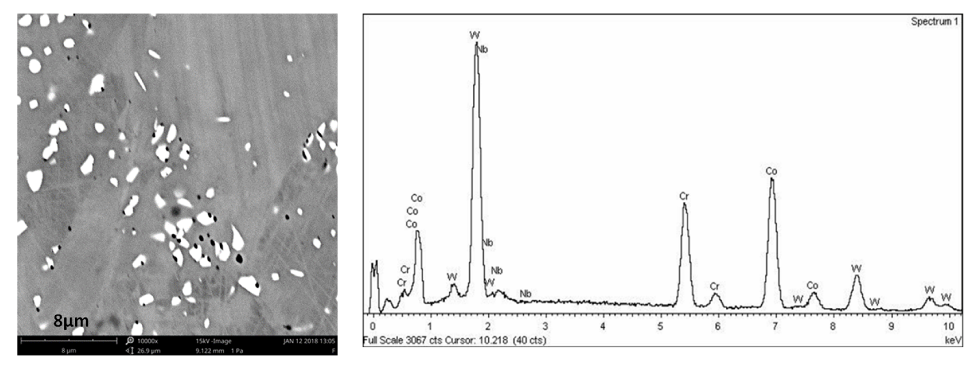
| Chemical Element | Co | Cr | W | Si | C | Nb |
|---|---|---|---|---|---|---|
| (wt%) | 56.53 ± 2.11 | 27.11 ± 1.31 | 9.64 ± 0.79 | 1.27 ± 0.80 | <1% | <1.5% |
| Properties/(Units) | Manufacturing Process/Results (mean ± STD) | ||
|---|---|---|---|
| CADCAM | Casting | Laser Sintering | |
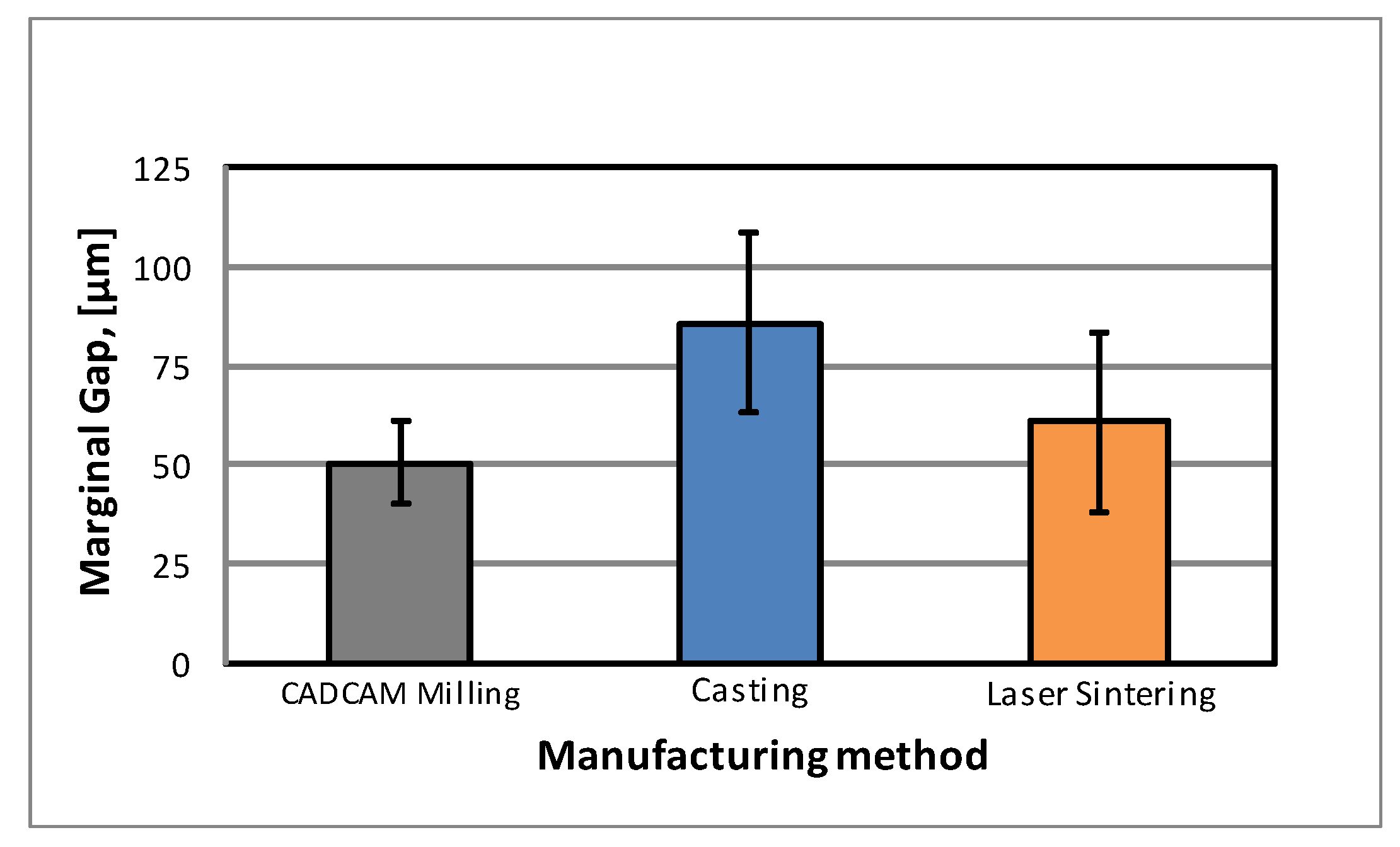
| Marginal Gap, (µm) | 50.53 ± 10.30 | 85.76 ± 22.56 | 60.95 ± 20.66 |
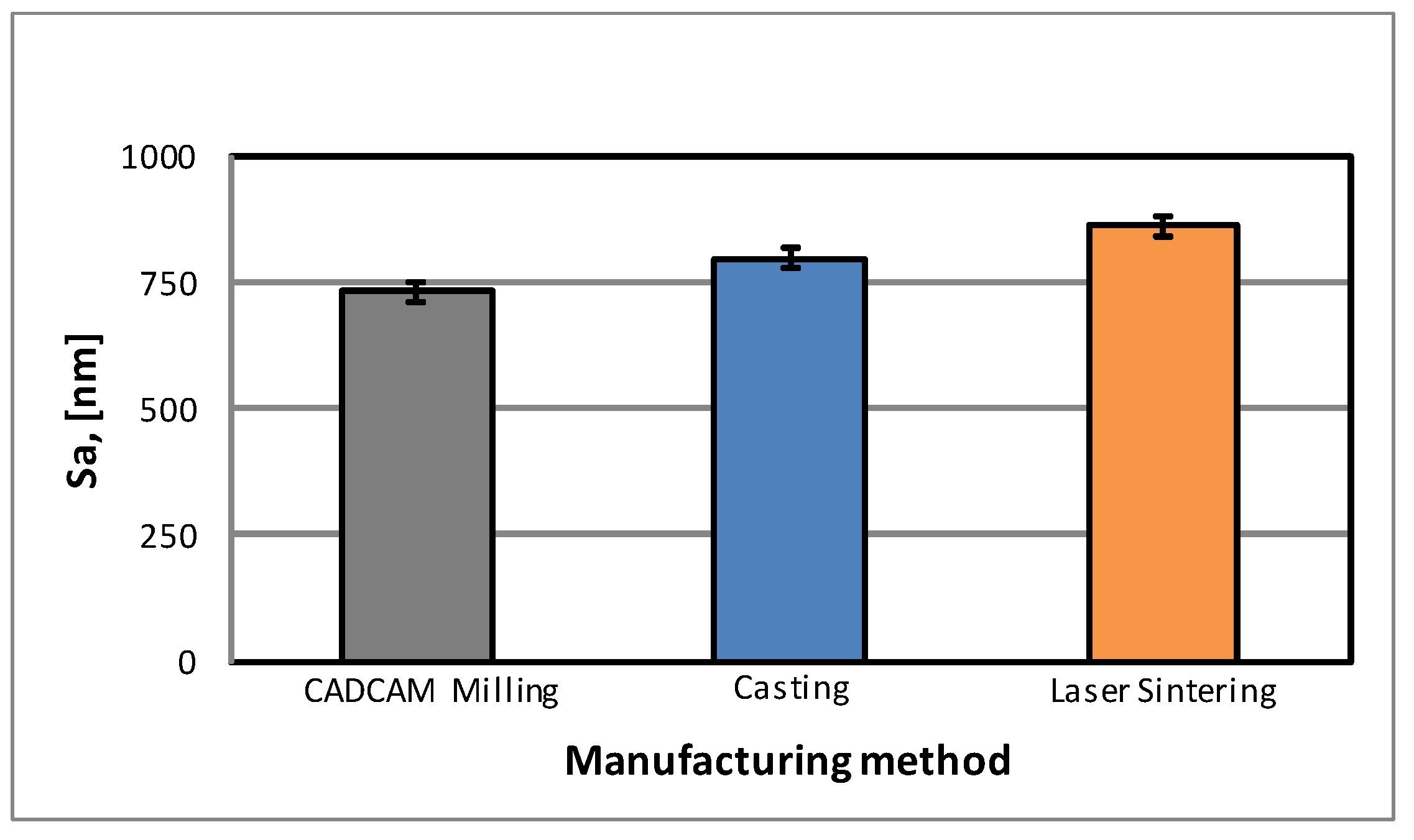
| Sa, (nm) | 731.27 ± 19.0 | 796.60 ± 19.8 | 859.5 ± 18.9 |
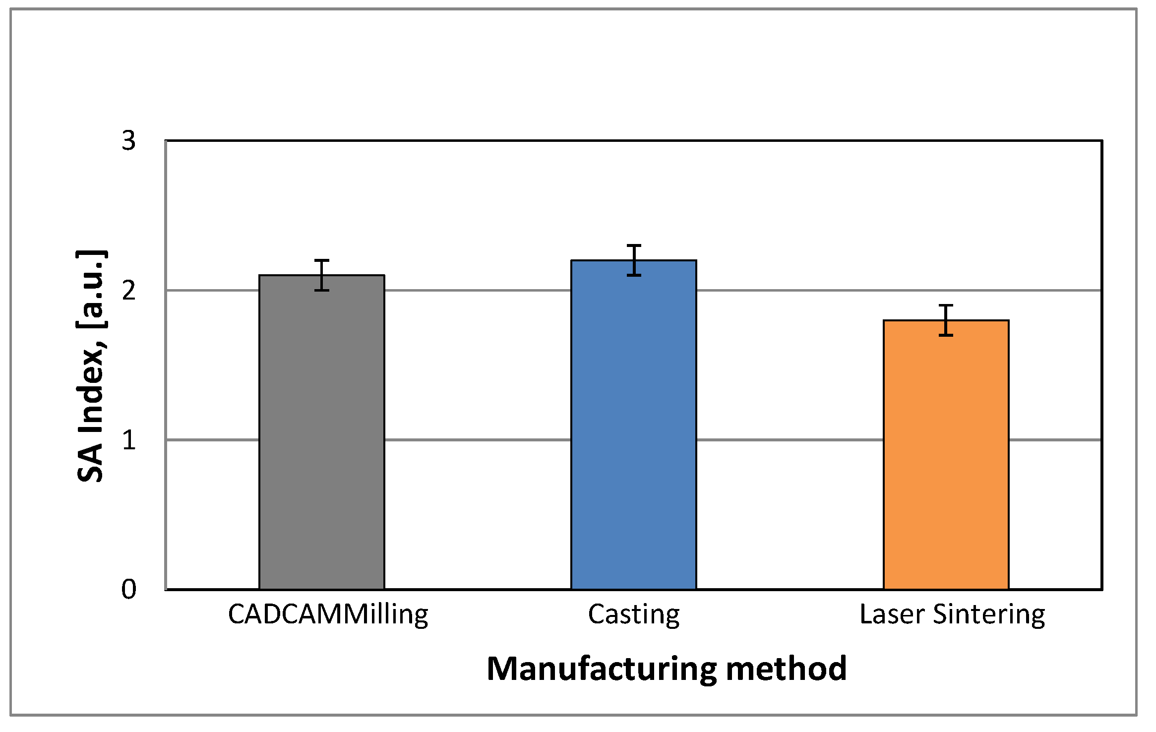
| SA Index area | 2.1 ± 0.1 | 2.2 ± 0.1 | 1.8 ± 0.1 |
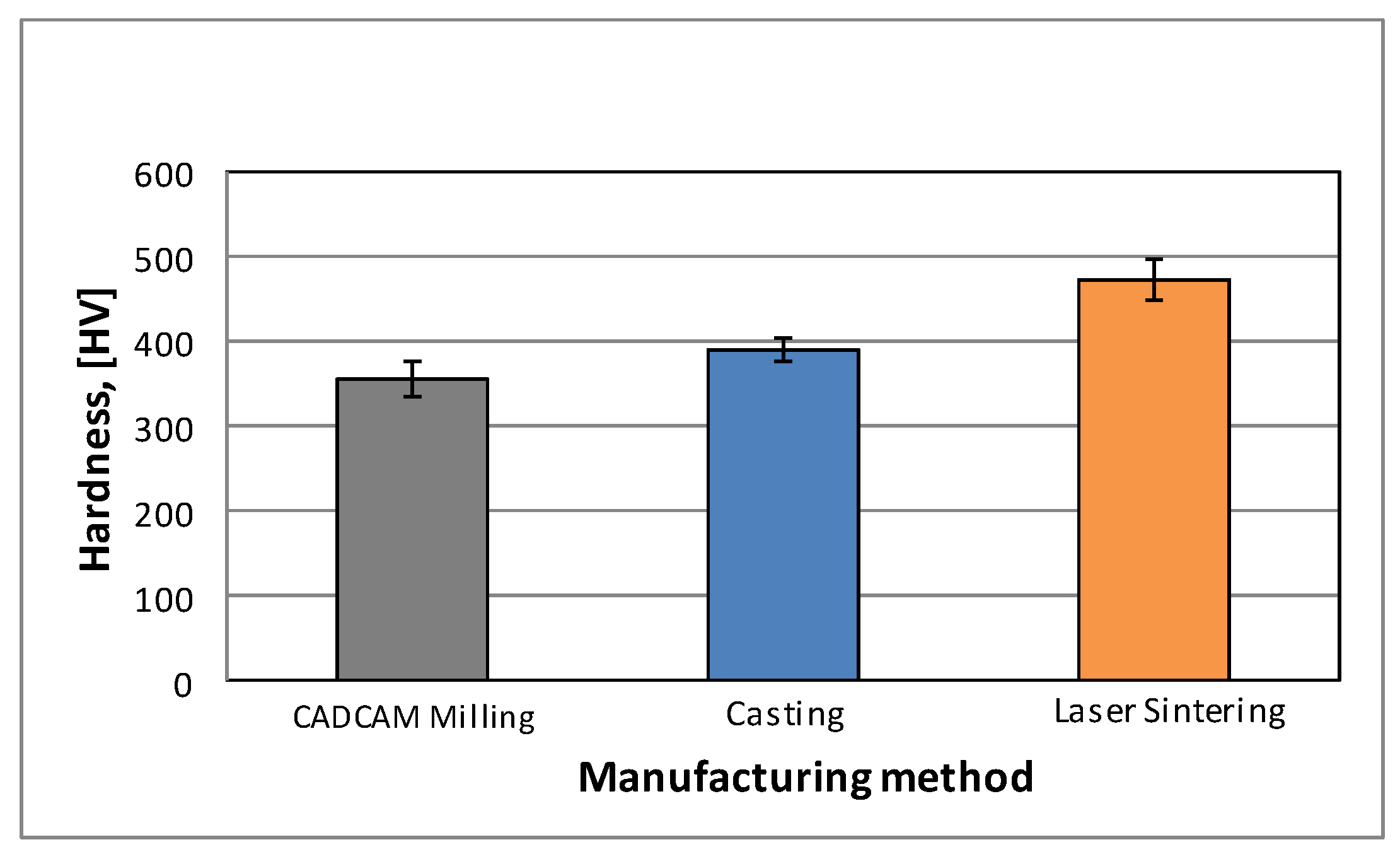
| Hardness, (HV) | 356 ± 20 | 390 ± 15 | 473 ± 25 |
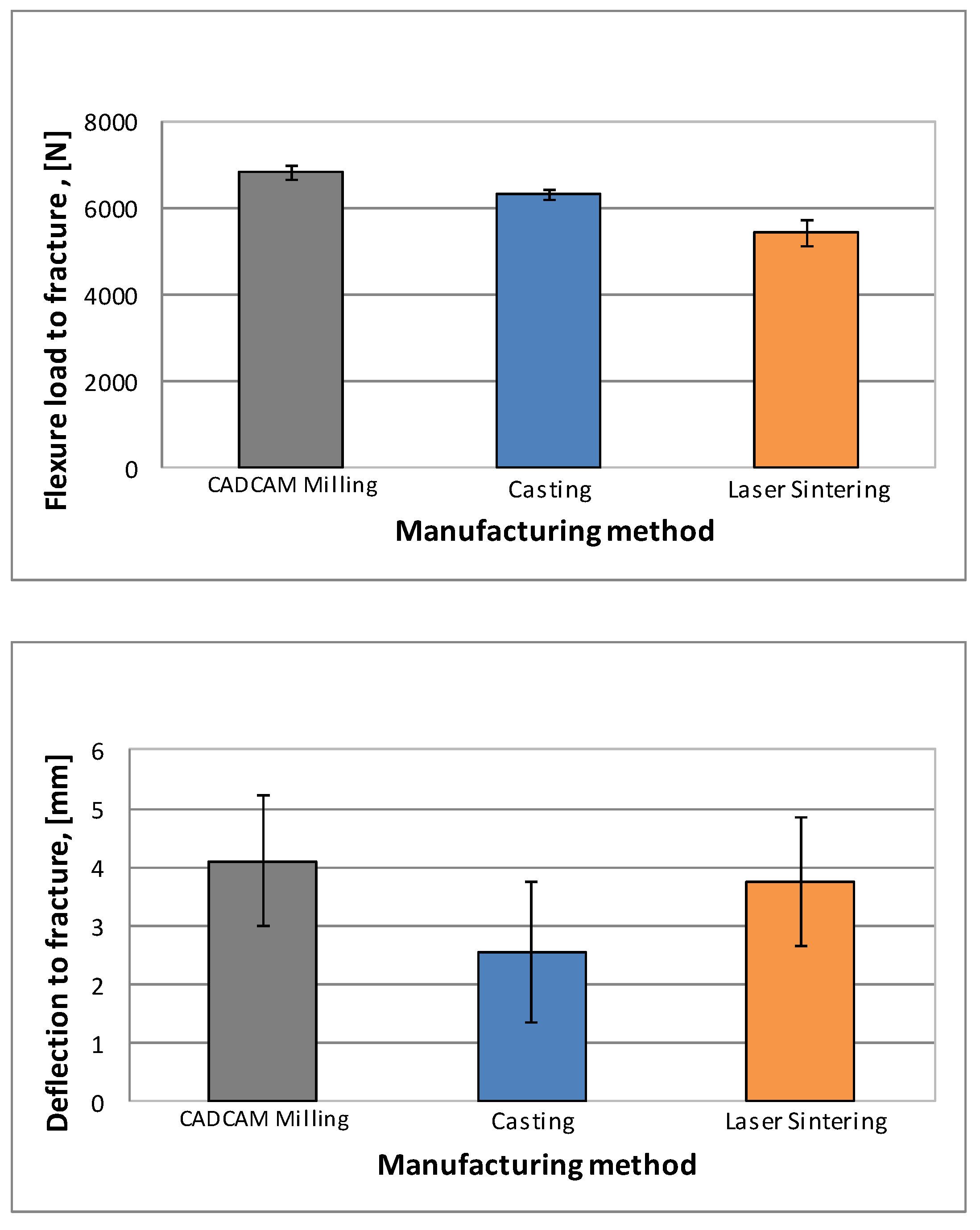
| Flexural load to fracture, (N) | 6813 ± 169 | 6291 ± 105 | 5422 ± 302 |
| Deflection to fracture, (mm) | 4.10 ± 1.12 | 2.55 ± 1.21 | 3.75 ± 1.10 |
© 2020 by the authors. Licensee MDPI, Basel, Switzerland. This article is an open access article distributed under the terms and conditions of the Creative Commons Attribution (CC BY) license (http://creativecommons.org/licenses/by/4.0/).
Share and Cite
Padrós, R.; Punset, M.; Molmeneu, M.; Velasco, A.B.; Herrero-Climent, M.; Rupérez, E.; Gil, F.J. Mechanical Properties of CoCr Dental-Prosthesis Restorations Made by Three Manufacturing Processes. Influence of the Microstructure and Topography. Metals 2020, 10, 788. https://doi.org/10.3390/met10060788
Padrós R, Punset M, Molmeneu M, Velasco AB, Herrero-Climent M, Rupérez E, Gil FJ. Mechanical Properties of CoCr Dental-Prosthesis Restorations Made by Three Manufacturing Processes. Influence of the Microstructure and Topography. Metals. 2020; 10(6):788. https://doi.org/10.3390/met10060788
Chicago/Turabian StylePadrós, Roberto, Miquel Punset, Meritxell Molmeneu, Aritza Brizuela Velasco, Mariano Herrero-Climent, Elisa Rupérez, and Francisco Javier Gil. 2020. "Mechanical Properties of CoCr Dental-Prosthesis Restorations Made by Three Manufacturing Processes. Influence of the Microstructure and Topography" Metals 10, no. 6: 788. https://doi.org/10.3390/met10060788
APA StylePadrós, R., Punset, M., Molmeneu, M., Velasco, A. B., Herrero-Climent, M., Rupérez, E., & Gil, F. J. (2020). Mechanical Properties of CoCr Dental-Prosthesis Restorations Made by Three Manufacturing Processes. Influence of the Microstructure and Topography. Metals, 10(6), 788. https://doi.org/10.3390/met10060788